Photon-Assisted Generation of Frequency 16-Tupling Millimeter Waves by Mach–Zehnder Modulators Without Filtering and Transmission over Fibers Without the Bit Walk-Off Effect

Abstract
:1. Introduction
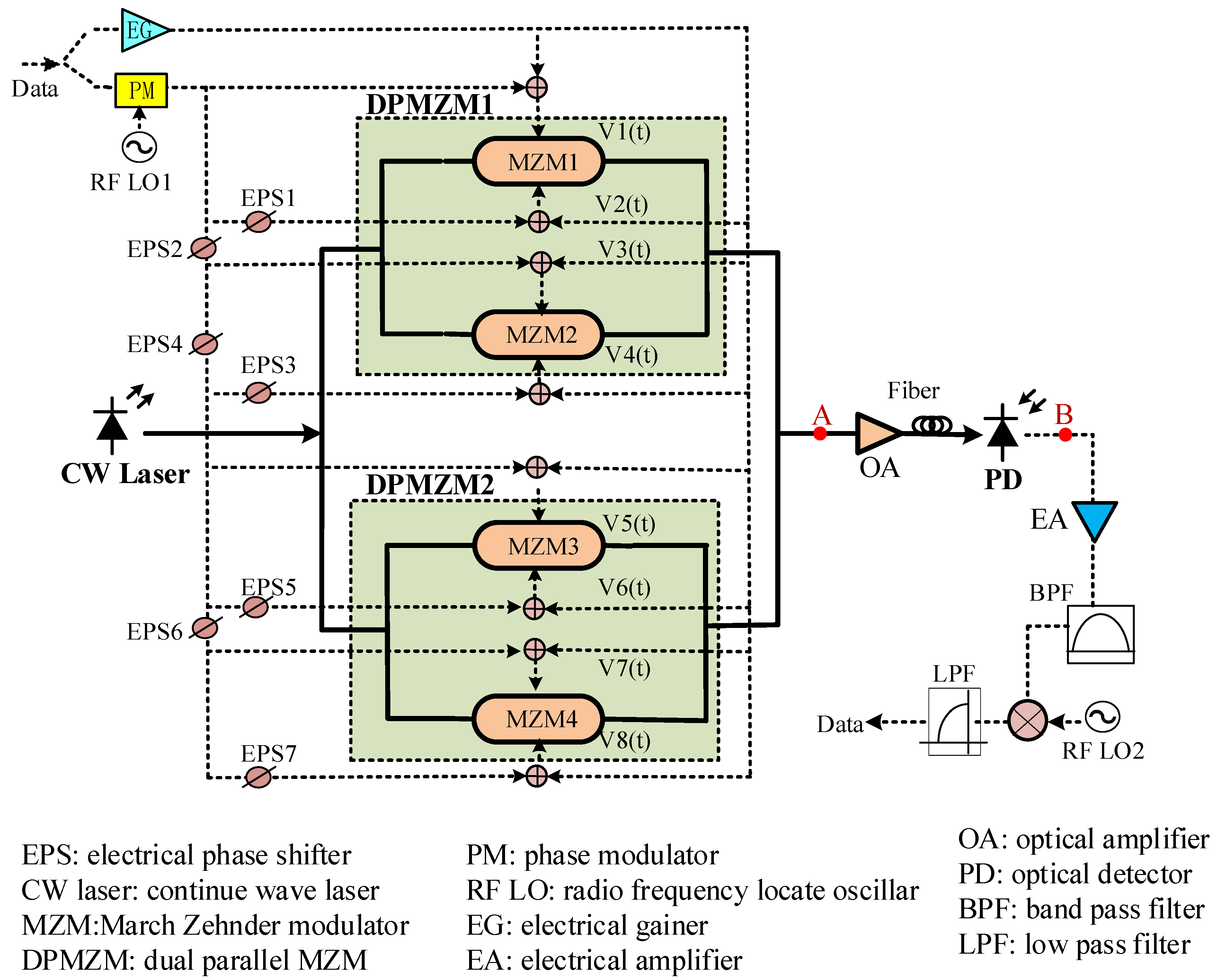
2. System Design
3. Operation Principle
3.1. Output Signal from MZMs
3.2. Selection of the Modulation Index of MZM
3.3. The Dispersion Effect on the Generated Frequency 16-Tupling MMW
4. Simulation Experiments
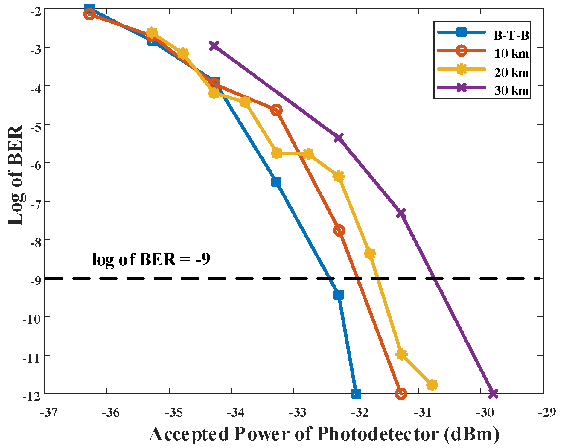
4.1. Transmission Test
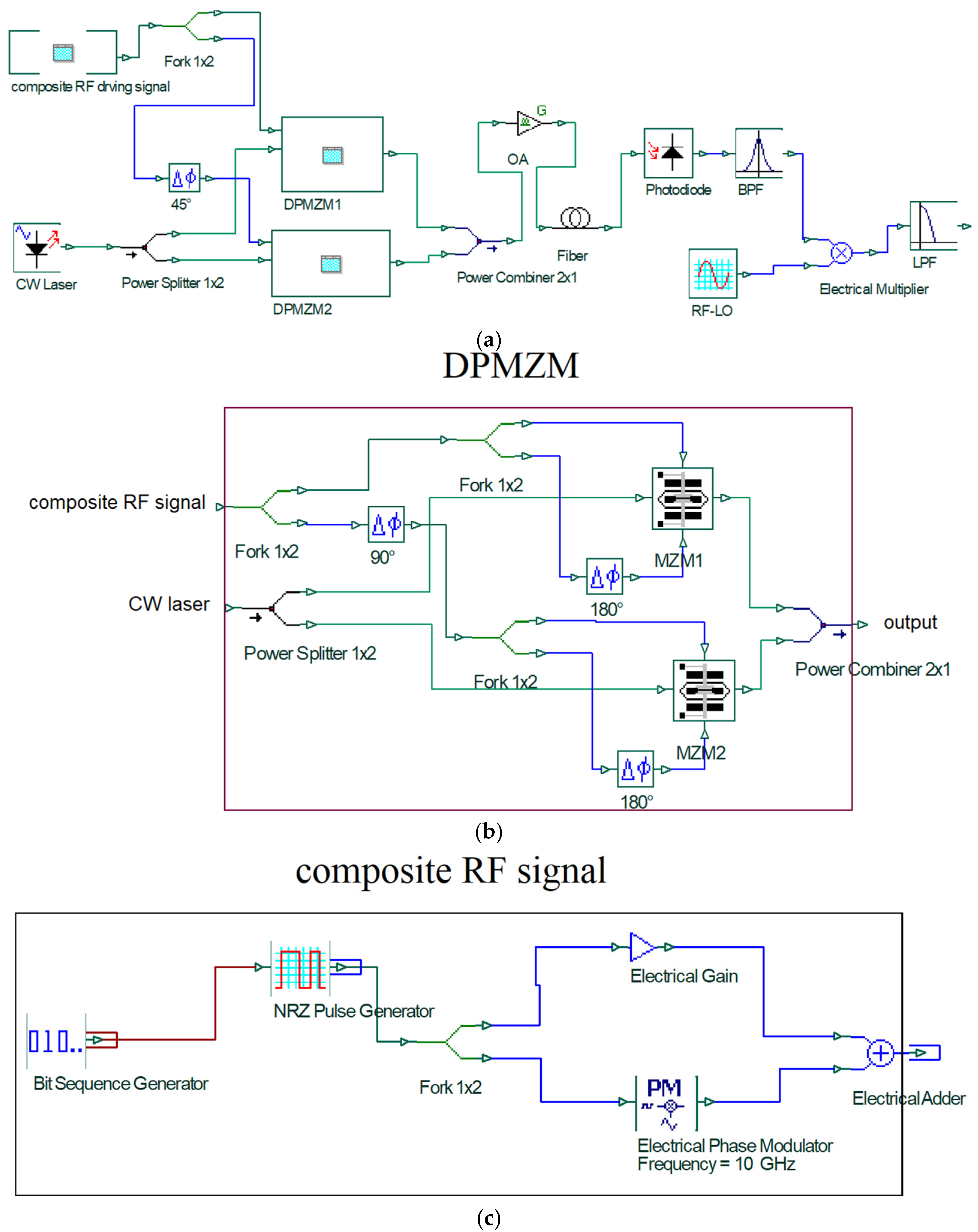
4.1.1. Simulation Circuit with OptiSystem
4.1.2. Simulation Parameter
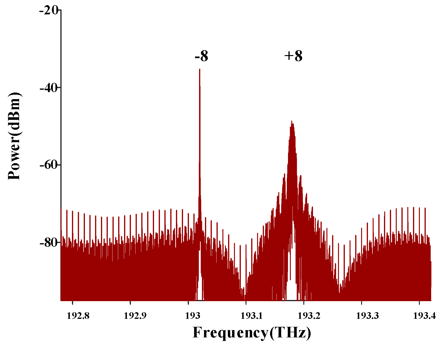
4.1.3. Simulation Experiment Results
4.2. Impact of Irrational Parameters on System Performance
4.2.1. Impact of Modulation Index of MZM
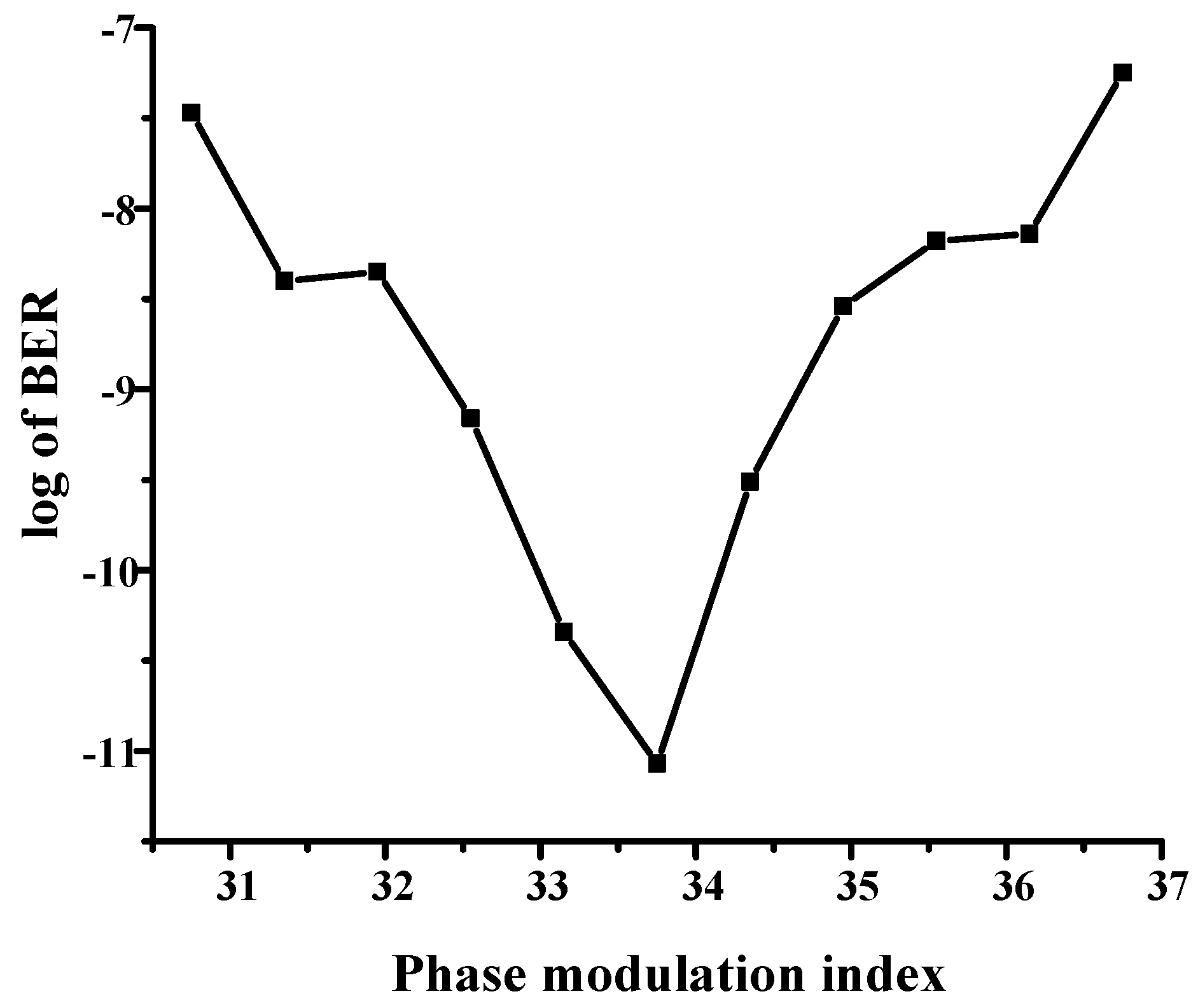
4.2.2. Effect of Phase Modulation Index P of PM
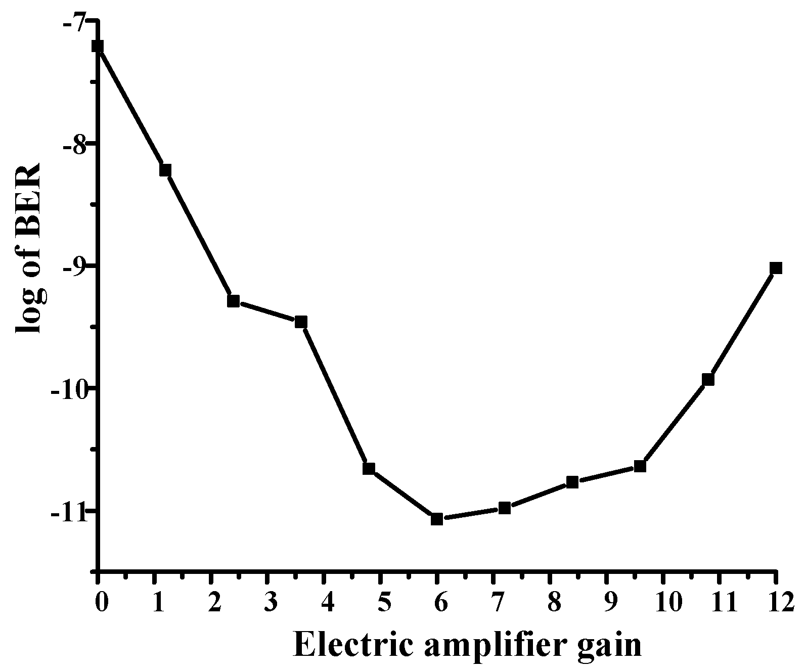
4.2.3. The Effect of the Gain G of EG
5. Discussion
- (1)
- Transmission distance
- (2)
- Scope of application
- (3)
- Carrier reuse
- (4)
- Nonlinear
- (5)
- The basis to choose the values of the PM’s P and the EG’s G.
- (6)
- Optical energy efficiency
6. Conclusions
Author Contributions
Funding
Institutional Review Board Statement
Informed Consent Statement
Data Availability Statement
Conflicts of Interest
References
- Han, M.; Li, M.; Wang, M.; Wu, B.; Yin, B.; Li, Y.; Liu, Y. Full-duplex multi-band 5G/6G coexistence mobile fronthaul network based on RoF with RF self-interference cancellation. Opt. Fiber Technol. 2023, 81, 103551. [Google Scholar]
- Kanno, A. Seamless Convergence Between Terahertz Radios and Optical Fiber Communication Toward 7G Systems. IEEE J. Sel. Top. Quantum Electron. 2023, 29, 103551. [Google Scholar]
- Yao, J. Microwave Photonic Systems. J. Light. Technol. 2022, 40, 6595–6607. [Google Scholar]
- Fatikah, A.P.; Natali, Y.; Apriono, C. Bidirectional Radio Over Fiber with Millimeter Wave to Support 5G Fronthaul Network. In Proceedings of the 2023 IEEE International Conference on Communication, Networks and Satellite (COMNETSAT), Malang, Indonesia, 23–25 November 2023. [Google Scholar]
- Ma, J.; Wang, M. Photonic self-interference cancellation for RoF-based in-band full-duplex link in wireless fronthaul access network. Opt. Fiber Technol. 2024, 84, 103722. [Google Scholar]
- Kumar, S.; Sharma, S.; Dahiya, S. WDM-Based 160 Gbps Radio Over Fiber System with the Application of Dispersion Compensation Fiber and Fiber Bragg Grating. Front. Phys. 2021, 9, 691387. [Google Scholar]
- Kamissoko, D.; He, J.; Ganame, H.; Tall, M. Performance investigation of W-band millimeter-wave radio-over-fiber system employing optical heterodyne generation and self-homodyne detection. Opt. Commun. 2020, 474, 126174. [Google Scholar]
- Zhang, J.H.; Cai, Q.B.; Li, Y.N.; Li, C.; Zhao, Z.G. An optoelectronic oscillator for millimeter waves generation based on an integrated optical waveguide ring-resonator. Optoelectron. Adv. Mater.-Rapid Commun. 2019, 13, 279–283. [Google Scholar]
- Lo, M.C.; Guzmán, R.; Gordón, C.; Carpintero, G. Mode-locked laser with pulse interleavers in a monolithic photonic integrated circuit for millimeter wave and terahertz carrier generation. Opt. Lett. 2017, 42, 1532–1535. [Google Scholar]
- Prem, A.; Chakrapani, A. Optical millimeter wave generation using External Modulation—A Review. Adv. Nat. Appl. Sci. 2017, 11, 8–12. [Google Scholar]
- Zhou, H.; Fei, C.; Zeng, Y.; Tan, Y.; Chen, M. A ROF system based on 18-tuple frequency millimeter wave generation using external modulator and SOA. Opt. Fiber Technol. 2021, 61, 102402. [Google Scholar]
- Zhu, M.; Tang, X.; Xi, L.; Zhang, W.; Zhang, X. Photonic generation of frequency-quadrupling millimeter-wave signals using polarization property. Opt. Eng. 2015, 55, 031106. [Google Scholar]
- Hasan, G.M.; Hasan, M.; Shang, H.; Sun, D.; Hinzer, K.; Liu, P.; Hall, T. Energy efficient photonic millimeter-wave generation using cascaded polarization modulators. Opt. Quantum Electron. 2019, 51, 217. [Google Scholar]
- Kumar, R.; Raghuwanshi, S.K. Photonic Generation of Multiple Shapes and Sextupled Microwave Signal Based on Polarization Modulator. IEEE Trans. Microw. Theory Tech. 2021, 69, 3875–3882. [Google Scholar]
- Zhu, Z.; Zhao, S.; Li, X.; Qu, K.; Lin, T. Photonic generation of frequency-sextupled microwave signal based on dual-polarization modulation without an optical filter. Opt. Laser Technol. 2017, 87, 1–6. [Google Scholar]
- Abouelez, A.E. Optical millimeter-wave generation via frequency octupling circuit based on two parallel dual-parallel polarization modulators. Opt. Quantum Electron. 2020, 52, 439. [Google Scholar] [CrossRef]
- Abouelez, A.E. Photonic generation of millimeter-wave signal through frequency 12-tupling using two cascaded dual-parallel polarization modulators. Opt. Quantum Electron. 2020, 52, 166. [Google Scholar]
- Baskaran, M.; Sevagan, S.; Sivasakthi, T. A Filterless Generation of Optical Millimeter Wave Signal Based on Frequency 16-Tupling Using Cascaded Polarization Modulators. IETE J. Res. 2023, 69, 7796–7802. [Google Scholar] [CrossRef]
- Yan, X.; Wang, D.; Li, Z.; Wang, X. A new scheme for the generation of frequency 18-tupling mm-wave signal based on three polarization modulators. Ukr. J. Phys. Opt. 2024, 25, 03019–03030. [Google Scholar]
- Banerjee Chaudhuri, R.; Das Barman, A.; Bogoni, A. Photonic 60 GHz sub-bands generation with 24-tupled frequency multiplication using cascaded dual parallel polarization modulators. Opt. Fiber Technol. 2020, 58, 102244. [Google Scholar] [CrossRef]
- Chen, X.Q.; Dai, S.Y.; Liu, X.R.; Chen, X.; Li, Z.H. Radio-over-fibre for generation and transmission 32-tupling frequency optical millimeter wave with polarization modulators. Opt. Appl. 2024, 54, 51–67. [Google Scholar]
- Rani, A.; Kedia, D. Photonic generation of frequency 12-tupling millimeter-wave based on three cascaded-MZMs and polarization multiplexing. Int. J. Commun. Systems. 2024, 37, e5769. [Google Scholar] [CrossRef]
- Wang, D.F.; Yan, X.Y.; Yang, Z.F.; Wang, X.Q.; Yang, X.K. A New Scheme to Generate Frequency 12-tupling Millimeter Wave Signals Only Based on Cascaded Three MZMs. Mathematics 2024, 12, 3759. [Google Scholar] [CrossRef]
- Wang, C.; Song, K.; Li, M.M.; Yi, Y.; Zhou, M.T.; Wu, J.H. Generation of frequency 16-tupling millimeter wave without filtering based on cascaded Mach-Zehnder modulator. Microw. Opt. Technol. Lett. 2024, 66, e33904. [Google Scholar] [CrossRef]
- Chen, X.; Chen, X.Q.; Dai, S.Y.; Li, B.; Wang, L. A Novel Inserting Pilot Radio over Fiber System without the Bit Walk-Off Effect for the Generation and Distribution of Frequency 16-Tupling Millimeter Waves by Mach-Zehnder Modulators. Photonics 2024, 11, 410. [Google Scholar] [CrossRef]
- Chen, X.Q.; Dai, S.Y.; Li, Z.H.; Xiao, H.B.; Zhang, L.; Chen, X. Study of the generation of two frequency 16-tupling millimeter wave and transmission over fiber by remodulation with Mach-Zehnder modulators. Opt. Quantum Electron. 2024, 56, 539. [Google Scholar]
- Rani, A.; Kedia, D. An 18-Tupled Photonic Millimeter-Wave Generation Using Cascaded Mach-Zehnder Modulators. Fiber Integr. Opt. 2023, 42, 1–19. [Google Scholar] [CrossRef]
- Rani, A.; Kedia, D. Mathematical analysis of 24-tupled mm-wave generation using cascaded MZMs with polarization multiplexing for RoF transmission. Opt. Quantum Electron. 2024, 56, 193. [Google Scholar] [CrossRef]
- Wang, S.; Wang, D.; Ren, L.; Zhang, H.; Wu, Z.; Li, W.; Zhang, F.; Wang, X. Photon Generation Scheme of 32-Fold Millimeter-Wave Signal Based on Mach-Zehnder Modulator. Annalen Der Physik. 2024, 536, 2300360. [Google Scholar]
- Asha Dahiya, S. Design and analysis of 160 GHz millimeter wave RoF system with dispersion tolerance. J. Opt. 2023, 52, 1461–1476. [Google Scholar]
- Ali, S.H.; Al-Maqdici, R.Z.Y. Improving the performance of cost-effective millimeter wave-based front-haul RoF system for up to 140 km link length using predistortion device and FBG technique. Soft Comput. 2022, 28, 787. [Google Scholar]
- Zhou, M.; Ma, J. The influence of fiber dispersion on the transmission performance of a quadruple-frequency optical millimeter wave with two signal modulation formats. Opt. Switch. Netw. 2012, 9, 343–350. [Google Scholar]
- Ma, J.; Yu, J.; Yu, C.; Xin, X.; Zeng, J.; Chen, L. Fiber Dispersion Influence on Transmission of the Optical Millimeter-Waves Generated Using LN-MZM Intensity Modulation. J. Light. Technol. 2007, 25, 3244–3256. [Google Scholar]
- Wang, Y.Q.; Pei, L.; Li, J.; Li, Y.Q. Study on the dispersion characteristic of different code data transmission pulses in OSSB-RoF system. Opt. Quantum Electron. 2016, 48, 426. [Google Scholar]
- Arya, R.; Zacharias, J. Performance improved tunable millimeter-wave signal generation employing UFBG based AOTF with bit walk-off effect compensation. Microw. Opt. Technol. Lett. 2019, 61, 1221–1230. [Google Scholar]
- Chen, Y.; Wen, A.; Yin, X.; Shang, L.; Wang, Y. Generation of frequency-doubling mm-wave signal using a Mach–Zehnder modulator with three arms to overcome fiber chromatic dispersion. Opt. Fiber Technol. 2012, 18, 1–6. [Google Scholar]
- Niknamfar, M.; Shatram, M. Two Sub-Carriers Multiplexed Millimeter Wave Generation Using Mach-Zehnder Modulators. In Proceedings of the 2014 16th International Conference on Transparent Optical Networks (ICTON), Graz, Austria, 6–10 July 2014. [Google Scholar]
- Wibisono, G.; Ujang, F.; Firmansyah, T.; Priambodo, P.S. Asymmetric Carrier Divider with an Irregular RF Phase on DD-MZ Modulator for Eliminating Dispersion Power Fading in RoF Communication. Photonics-Basel. 2020, 7, 106. [Google Scholar]
- Asha; Dahiya, S. Optical Carrier Suppression Based Single Sideband Millimeter wave Transmission for 5G RoF System. In Proceedings of the 2021 IEEE 2nd International Conference on Applied Electromagnetics, Signal Processing, & Communication (AESPC), Bhubaneswar, India, 26–28 November 2021. [Google Scholar]
- Liu, X.; Liu, Z.; Li, J.; Shang, T.; Zhao, J. Generation of optical carrier suppression millimeter-wave signal using one dual-parallel MZM to overcome chromatic dispersion. Opt. Commun. 2010, 283, 3129–3135. [Google Scholar]
- Zhu, Z.; Zhao, S.; Li, Y.; Chu, X.; Wang, X.; Zhao, G. A Radio-Over-Fiber System with Frequency 12-Tupling Optical Millimeter-Wave Generation to Overcome Chromatic Dispersion. IEEE J. Quantum Electron. 2013, 49, 919–922. [Google Scholar]
- Zhu, Z.; Zhao, S.; Yao, Z.; Tan, Q.; Li, Y.; Chu, X.; Shi, L.; Zhang, X. Optical millimeter-wave signal generation by frequency quadrupling using one dual-drive Mach–Zehnder modulator to overcome chromatic dispersion. Opt. Commun. 2012, 285, 3021–3026. [Google Scholar]
- Zhu, Z.; Zhao, S.; Yao, Z.; Tan, Q.; Li, Y.; Chu, X.; Shi, L.; Hou, R. A novel OCS millimeter-wave generation scheme with data carried only by one sideband and wavelength reuse for uplink connection. Opt. Laser Technol. 2012, 44, 2366–2370. [Google Scholar]


| Reference | FMF | Method | Characteristic |
|---|---|---|---|
| [30,31,32] | 4, 6, 12 | filter method | high loss, poor tunability |
| [40] | 2 | two MZM | Complex, FMF low, filterless |
| [41,42,43] | 2, 4, 12 | composite RF signal | FMF low, filterless |
| Our scheme | 16 | composite RF signal as the drive signal of the MZM | FMF high, filterless |
| Device Name | Parameter | Value |
|---|---|---|
| CW | Frequency | 193.1 THz |
| Linewidth | 10 MHz | |
| Power | 0 dBm | |
| data | rate | Gbps |
| Modulation mode | NRZ | |
| RF-LO | Frequency | 10 GHz |
| Amplitude | 7.0284 V | |
| phase modulator | P | 3π/16 |
| electrical gainer | G | 6 |
| MZM | Vπ | 4 V |
| Insertion loss | 5 dB | |
| Extinction ratio | 40 dB | |
| Fiber | Dispersion Loss | 16.75 ps/nm/km 0.2 dB/km |
| OA | Gain | 25 dB |
| Noise figure | 4 dB | |
| PD | Responsivity | 1 A/W |
| BPF | Frequency | 160 GHz |
| Bandwidth | 1.5 bit rate | |
| LPF | Cutoff frequency | 2.5 GHz |
Disclaimer/Publisher’s Note: The statements, opinions and data contained in all publications are solely those of the individual author(s) and contributor(s) and not of MDPI and/or the editor(s). MDPI and/or the editor(s) disclaim responsibility for any injury to people or property resulting from any ideas, methods, instructions or products referred to in the content. |
© 2025 by the authors. Licensee MDPI, Basel, Switzerland. This article is an open access article distributed under the terms and conditions of the Creative Commons Attribution (CC BY) license (https://creativecommons.org/licenses/by/4.0/).
Share and Cite
Qun, W.; Chen, X.; Chen, X. Photon-Assisted Generation of Frequency 16-Tupling Millimeter Waves by Mach–Zehnder Modulators Without Filtering and Transmission over Fibers Without the Bit Walk-Off Effect. Photonics 2025, 12, 354. https://doi.org/10.3390/photonics12040354
Qun W, Chen X, Chen X. Photon-Assisted Generation of Frequency 16-Tupling Millimeter Waves by Mach–Zehnder Modulators Without Filtering and Transmission over Fibers Without the Bit Walk-Off Effect. Photonics. 2025; 12(4):354. https://doi.org/10.3390/photonics12040354
Chicago/Turabian StyleQun, Wang, Xu Chen, and Xinqiao Chen. 2025. "Photon-Assisted Generation of Frequency 16-Tupling Millimeter Waves by Mach–Zehnder Modulators Without Filtering and Transmission over Fibers Without the Bit Walk-Off Effect" Photonics 12, no. 4: 354. https://doi.org/10.3390/photonics12040354
APA StyleQun, W., Chen, X., & Chen, X. (2025). Photon-Assisted Generation of Frequency 16-Tupling Millimeter Waves by Mach–Zehnder Modulators Without Filtering and Transmission over Fibers Without the Bit Walk-Off Effect. Photonics, 12(4), 354. https://doi.org/10.3390/photonics12040354