Article

Novel Focusing Performances of High-Numerical-Aperture Micro-Fresnel Zone Plates with Selective Occlusion

1
School of Mechanical Engineering, Shaanxi University of Technology, Hanzhong 723000, China
2
Shaanxi Key Laboratory of Industrial Automation, Shaanxi University of Technology, Hanzhong 723000, China
*
Author to whom correspondence should be addressed.
Photonics 2025, 12(4), 372; https://doi.org/10.3390/photonics12040372
Submission received: 18 March 2025 / Revised: 9 April 2025 / Accepted: 11 April 2025 / Published: 13 April 2025

Abstract

:
In this study, novel focusing performances of high-numerical-aperture (NA) micro-Fresnel zone plates (FZPs) with selective occlusion are identified and investigated through numerical calculations based on vectorial angular spectrum (VAS) theory, and further rigorously validated using the finite-difference time-domain (FDTD) method. The central occlusion of a standard micro-FZP can significantly extend the depth of focus while keeping the lateral size of the focusing spot essentially unchanged. When a standard micro-FZP only retains two separated transparent rings and all other rings are obstructed, it will result in multi-focus phenomena; at the same time, the number of focal points is equal to the difference in number between the two separated transparent rings. Furthermore, a focusing light needle can be generated by combining the central occlusion and wavelength shift of a standard micro-FZP. This study not only provides new ideas for the design and optimization of micro-FZPs but also provides reference for the expansion of practical applications of FZPs.

1. Introduction

Fresnel zone plates (FZPs) are typical planar diffractive lenses [1,2,3,4] which possess a focusing function similar to that of ordinary refractive lenses while providing advantages that ordinary refractive lenses cannot match; for example, they can focus not only visible light, but also infrared, ultraviolet, and even X-ray radiation. Furthermore, FZPs have a lightweight structure and excellent focusing performance, which contribute to the miniaturization and integration of optical systems. Therefore, FZPs have been widely used in remote communication [5,6,7], photolithography [8,9], high-resolution microscopy imaging [10,11,12], three-dimensional holography [13,14], telescope systems [15,16], and other fields. For low-numerical-aperture (NA) FZPs, a characteristic feature is the presence of multi-focus along the axial direction at defined distances [17]. Conversely, high-NA FZPs (NA > 0.3) are distinguished by a single focus along this axis [18,19,20,21]. In recent years, research on the focusing performance of high-NA FZP has been further developed. For example, Minin et al. first proposed an FZP beyond the Abbe diffraction limit and applied it to near-field millimeter wave imaging systems [22]. Zhang et al. proposed a vector diffraction model based on vector Rayleigh–Sommerfeld integration, which combines analytical calculations of surface scattering and multiple reflections in groove regions, providing an effective tool for the design optimization of high-NA sub-wavelength FZPs [23]. Meanwhile, the vector diffraction theory of Richards and Wolf has been used to analyze the influence of shadow effects caused by etching depth on the focusing performance of high-NA binary phase FZPs [24]. Liu et al. proposed the Jiang–Wilson formula for the calculation of the axial focal size using vector angular spectrum theory and the three-dimensional finite-difference time-domain method, revealing the linear relationship between the lateral focal size and the outermost ring width [25]. Xue et al. further found that the axial focal size of a high-NA FZP is proportional to the reciprocal of the total number of rings, and wavelength dispersion causes linear negative focal shift [26]. Moreover, multi-focal or optical needle control can be achieved through the use of composite high-NA FZPs [26]. In general, the superior focusing ability of high-NA FZPs and their potential applications in super-resolution imaging have attracted considerable attention, especially for micro-FZPs [26,27,28,29].
A micro-FZP is composed of a series of concentric rings at the micro–nano scale with different ring widths. Through the fine coherent superposition of rings boundaries diffracted beams, a focusing spot is formed in the far field [1,2,3]. Due to the fact that the focusing of a micro-FZP is generated by fine diffraction, manufacturing errors or occlusions can cause changes in the focusing performances, thereby affecting the practical use of micro-FZPs. In particular, the influences of manufacturing errors on concentric circular ring structures similar to FZPs have been systematically studied. For example, in Ref. [30], the influences of transverse and longitudinal manufacturing errors of the ring on focusing performance were studied, while in Ref. [31], the influences of processing errors such as coating thickness, metal groove sidewall inclination, and roughness on focusing performance were studied. However, there has been no systematic study on the impact of occlusion on the focusing performances of micro-FZPs. We recently found that, when a high-NA micro-FZP is selectively blocked, it will produce some novel focusing performances. Therefore, this article adopts vectorial angular spectrum (VAS) theory combined with the three-dimensional finite-difference time-domain (FDTD) method to systematically explore the impacts of several typical occlusion methods on the focusing performance of a micro-FZP, providing a basis and foundation for the practical use of FZPs.

2. Materials and Methods

2.1. Micro-FZP

For a binary micro-FZP (a small scale FZP with a diameter less than 500 μm), the focusing process can be understood as the first-order diffraction of a circular grating [32], as shown in Figure 1.
In a right-angled triangle, the focal length f is taken as one side of the right-angle, while the radius rn of any ring is taken as the other side. Then, f + /2 is the length of the hypotenuse, where λ is the incident light wavelength and n = 0, 1, 2, 3, …, N (N represents the total number of rings). According to geometric relationships, it can be concluded that
f 2 + r n 2 = ( f + n λ / 2 ) 2
Through expansion and merging, the formula for a micro-FZP ring radius can be obtained as follows [33,34,35]:
r n = n λ f + n 2 λ 2 / 4 , n = 0 , 1 , 2 , , N .
For a binary amplitude-type micro-FZP, the transmittance function t(r) can be expressed as
t ( r ) = 1 , r 2 q < r r 2 q + 1 0 , r 2 q + 1 < r r 2 q + 2
where q = 0, 1, …, L/2 − 1 (L is an even number) and the values of 1 and 0 are utilized to designate the presence and absence of material in the annular zones, respectively, indicating transparency and opacity. In the case of a binary phase-type micro-FZP, the representation is modified by replacing the value of 0 with −1 in Equation (3). This alteration introduces a phase shift of π radians between the zones coded using −1 and 1.

2.2. VAS Representation for Micro-FZPs

For large-scale FZPs and small-NA FZPs, scalar diffraction theory is usually adopted for the calculation of their focusing light field distribution, which ignores the vector nature of the incident light in the solution process. However, for a high-NA micro-FZP, scalar theory cannot accurately calculate the propagation light field distribution of the micro-FZP due to the lack of consideration of the vector nature of the actual incident light field. Therefore, vector diffraction theory must be used to analyze the focusing light field distribution of a high-NA micro-FZP [20,36]. For the calculation of a micro-FZP’s focusing light field distribution, due to its better applicability, the VAS theory is usually used [37]. First, according to Equations (2) and (3), the light field distribution on the rear surface of a micro-FZP can be obtained by multiplying the incident light field with the scalar transmission function of the micro-FZP. Furthermore, the light field distribution on any observation surface of the micro-FZP can be calculated using VAS theory. For x-polarized linearly polarized light (LPB), the electric field distribution at any point on any observation surface of a micro-FZP has been described in previous studies [38,39,40], as shown in Figure 1 and determined by Equation (4):
E x ( r , z ) = 0 2 π l A 0 ( l ) J 0 ( 2 π l r ) e j 2 π q ( l ) z d l E y ( r , z ) = 0 E z ( r , α , z ) = j cos α 0 2 π l 2 q ( l ) A 0 ( l ) J 1 ( 2 π l r ) e j 2 π q ( l ) z d l
where the amplitude coefficient A0(l) is defined as A 0 ( l ) = 0 t ( r ) J 0 ( 2 π l r ) 2 π r d r ; l denotes the radial spatial frequency component; J0 and J1 represent the zeroth and first-order Bessel functions of the first kind, respectively; and q ( l ) = ( 1 / λ 2 l 2 ) 1 / 2 governs the propagation characteristics.
According to the integral expression of the field distribution at any point, the calculation of the micro-FZP focusing light field distribution can be implemented using Matlab software (R2024b, MathWorks, Natick, MA, USA) programming.

2.3. Rigorous Electromagnetic Validation of Micro-FZPs

In the previous section, when using VAS theory to calculate the focusing light field distribution of a micro-FZP, the propagation process of the illumination vector beam from the front surface to the back surface of the micro-FZP is approximated by a scalar processing method using thin elements, ignoring the propagation process of electromagnetic waves inside the micro-FZP. Therefore, in order to rigorously verify the accuracy of the focusing light field results based on VAS theory, a rigorous electromagnetic field solving method (finite-difference time-domain, FDTD) is usually used. This study uses a commercial numerical simulation software for FDTD solution (2018a, Ansys Lumerical FDTD, Canonsburg, PA, USA) in order to model and rigorously simulate the focusing light field distribution of the micro-FZPs, the reliability of which has been widely recognized [21,37,38,41,42]. In the FDTD simulation model, to enhance the focusing performance and minimize the fabrication expenses of the amplitude-type micro-FZP, a 100 nm thick Al film was selected as the shielding layer to effectively block the incident light [43]. The grid size of the simulation area in the x, y, and z directions was 30 nm. The simulation boundary condition was the perfectly matched layer (PML), whose wave impedance is highly matched with the adjacent wave impedance, such that there was no reflection of electromagnetic waves. Meanwhile, due to the circular symmetry structure of the micro-FZP, symmetric/asymmetric boundary conditions can be set according to different incident polarized light to reduce the memory required for simulation and provide computational efficiency.

3. Results and Discussion

To investigate the effect of selective occlusion on the focusing performance of high-NA micro-FZPs, two typical micro-FZPs were designed, with their specific design parameters shown in Table 1. In this study, λ is the wavelength of the incident light, η is the refractive index of the immersed medium, N is the total number of rings in the micro-FZPs, f is the focal length, and NA is the numerical aperture of the micro-FZPs. According to Equation (2), the radius of each annulus in micro-FZP1 and micro-FZP2 are provided in Table 2 and Table 3, respectively.
Furthermore, based on VAS theory and the FDTD method, the above two micro-FZPs were used to investigate the effects of three typical selective occlusions (central occlusion, intermittent occlusion of different rings, and a combination of central occlusion and wavelength shift) on the focusing performance of high-NA micro-FZPs.

3.1. Central Occlusion

In order to accurately evaluate the impact of central occlusion on the focusing performance of micro-FZPs, micro-FZP1 and micro-FZP2 were used to explore the effects of central occlusion on the size and position of the focusing spot based on VAS theory and the FDTD method. The focusing performance of a micro-FZP is mainly characterized by the focal length and the size of the focal spot. FZ represents the actual focal length of a micro-FZP, and FWHMx, FWHMy, and FWHMz (full width at half maximum) represent the sizes of the focal points in the three directions (i.e., x, y, and z, respectively).
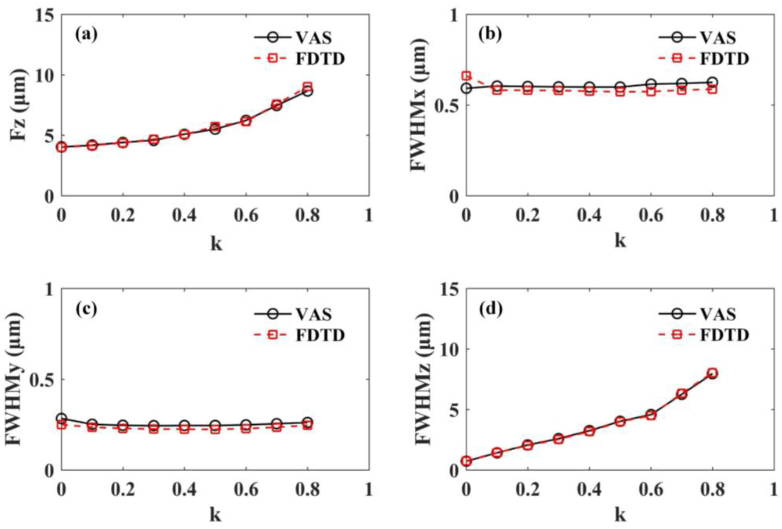
The parameters of micro-FZP1 are shown in Table 1 and Table 2, and the VAS and FDTD calculation results are shown in Table 4 and Figure 2; here, k = rM/rN represents the normalized occlusion factor and M is the total number of rings in the central occlusion region. From Figure 2, it can be seen that the VAS and FDTD calculation results were basically consistent. As k increases, the focusing spot moves forward along the z-axis. When k is within the range of 0–0.3, the focal length offset is small. When k is within the range of 0.3–0.6, the focal length offset slowly increases. When k is greater than 0.6, the focal length offset increases significantly, as shown in Figure 2a. Regarding the change in the size of the focusing spot, as k increases, the lateral size of the focusing spot changes relatively little, while the axial size of the focusing spot shows a significant increase, as shown in Figure 2b–d. In addition, it was found that the lateral size of the focusing spot in the x direction is larger than that in the y direction; the reason for this is that x-polarized LPB is used in this study, such that Ey component is 0, as shown in Equation (4). Similarly, for a y-polarized LPB, the lateral size of the focusing spot in the y direction would be larger than that in the x direction. Under circularly polarized beam (CPB) illumination, the diffractive wavefront maintains rotational symmetry but yields an expanded lateral focusing spot compared to LPB. Conversely, a radially polarized beam (RPB) generates a circularly symmetric lateral focal profile with enhanced sharpness relative to LPB illumination, attributed to the effective suppression of radial polarization components in the electric field [38,39,40,44].
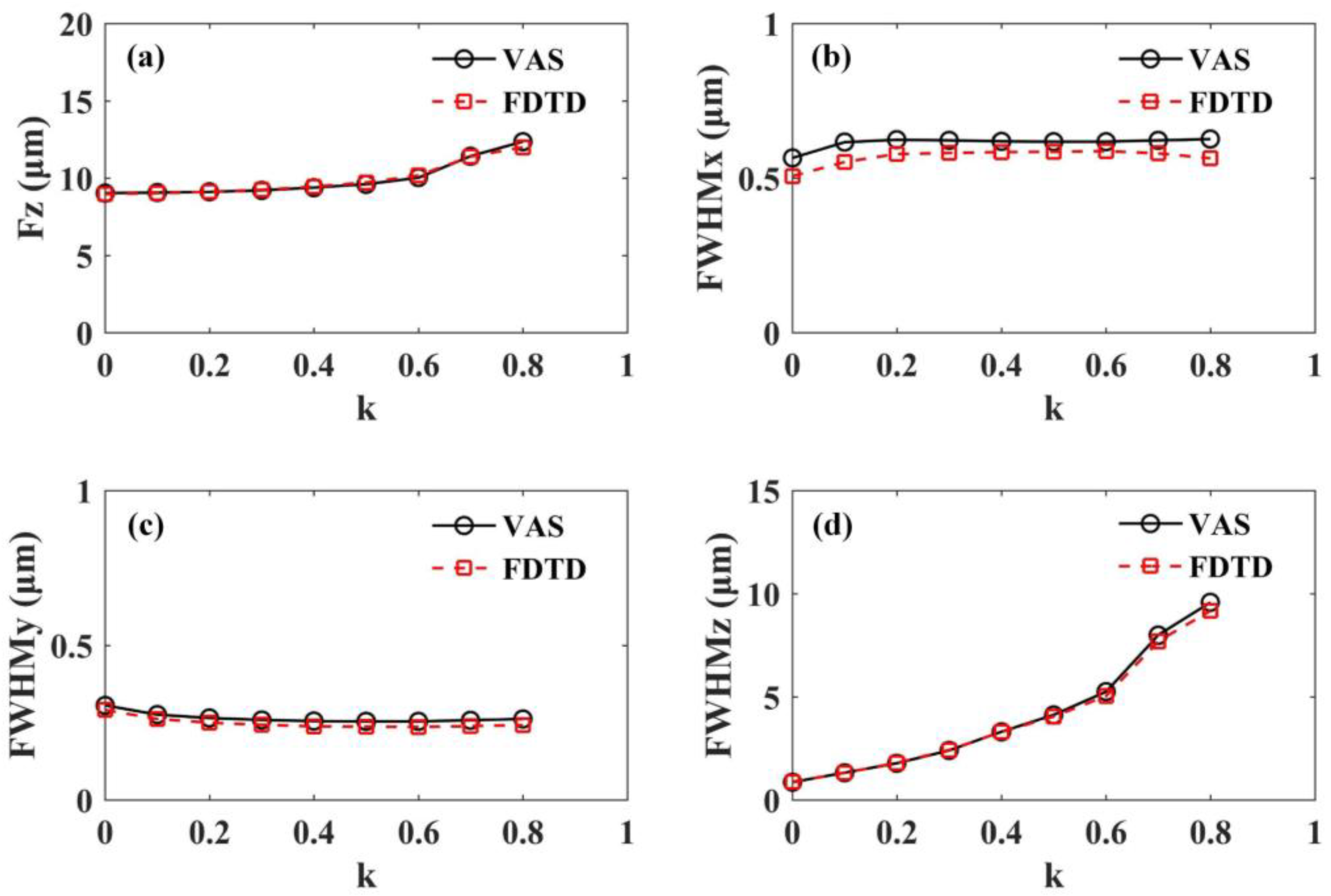
The parameters of micro-FZP2 are shown in Table 1 and Table 3, and the calculation results are provided in Table 5 and Figure 3, which presented a similar pattern to those for micro-FZP1. Overall, with an increase in the occlusion factor, the focusing spot of the micro-FZP moves along the positive z-axis, while the lateral size of the focusing spot remains basically unchanged and the axial size of the focusing spot significantly increases. At the same time, Figure 2 and Figure 3 demonstrate a slight difference between the results obtained using VAS and FDTD in the simulation examples. These discrepancies arise from the VAS approach’s inherent reliance on scalar diffraction approximations during wavefront reconstruction, which omits the rigorous treatment of material-dependent electromagnetic constitutive parameters—a critical consideration explicitly resolved through the full-wave numerical solution in FDTD [38,39,45].

3.2. Intermittent Occlusion of Different Rings

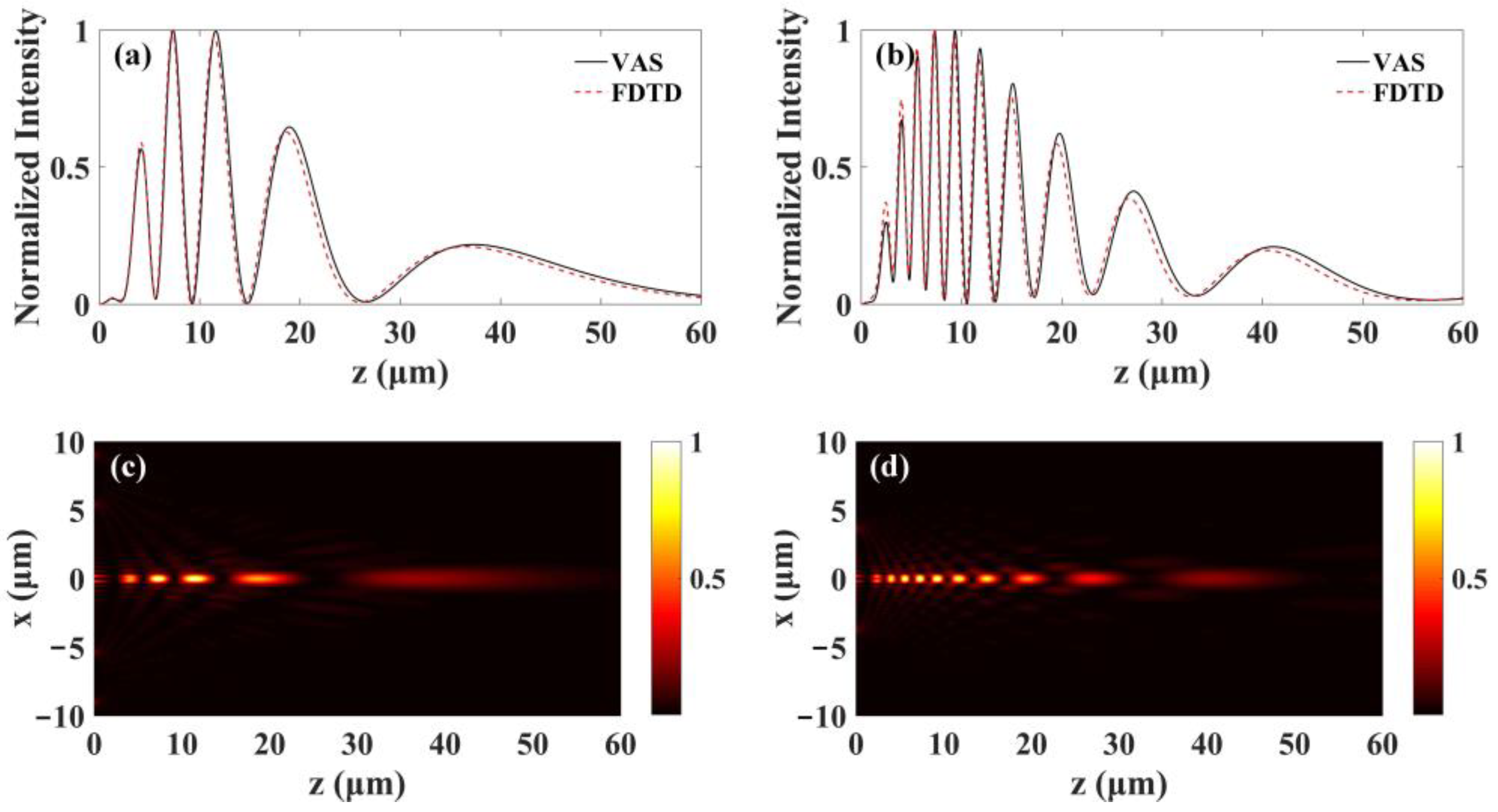
Micro-FZP1 and micro-FZP2 were used to investigate the effect of intermittent occlusion of different rings on the focusing performance of micro-FZPs. The basic principle of intermittent occlusion of different rings in this part is that only two discontinuous transparent rings in a standard micro-FZP were retained, while all other rings were occluded. For micro-FZP1, two shading methods were designed: (1) retaining the 5th and 10th transparent rings, while blocking the other rings; (2) retaining the 3rd and 13th transparent rings, while blocking the other rings. The calculation results with respect to the two occlusion methods are shown in Figure 4. Under both occlusion methods, the micro-FZP exhibited multi-focus phenomena. The multi-focus implementation method used in this study has fundamental differences in comparison with previous implementations; in particular, as it does not rely on the principle of super-oscillation, the method for generating multi-focus is much simpler [46,47].
In addition, it was found that when the 5th and 10th transparent rings were retained, while obstructing the other rings, five focal points were formed. Meanwhile, when the 3rd and 13th transparent rings were retained and the other rings were obstructed, 10 focal points formed. The calculation results for micro-FZP2 are shown in Figure 5, and its focus change pattern was similar to that of micro-FZP1. In general, the intermittent occlusion of different rings in micro-FZPs can cause multi-focus phenomena, where the number of focal points is positively correlated with the number of rings spaced between the transparent rings. Meanwhile, when ignoring the focal points with a normalized intensity of less than 0.2, the number of focal points is equal to the difference in number between the two separated transparent rings. The generation of multiple focal points enables the creation of optical multi-trap arrays, which are pivotal in advanced photonic applications.

3.3. Combination of Central Occlusion and Wavelength Shift

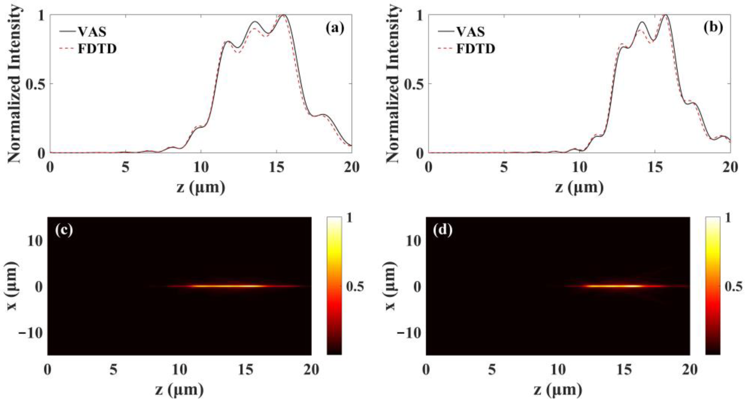
In Section 3.1, the impact of individual center occlusion on the focusing performance of micro-FZP was explored; however, different focusing performance may arise under other conditions. In this section, the changes in the focusing performance of micro-FZPs when center occlusion and wavelength shift coexist are explored. For micro-FZP1, the normalized center occlusion factor was k = 0.2 and the wavelength was shifted by −200 nm (actual wavelength, 433 nm). For micro-FZP2, the normalized center occlusion factor was k = 0.1 and the wavelength was shifted by -100 nm (actual wavelength, 533 nm). The VAS and FDTD calculation results are shown in Figure 6. Figure 6a,c show the focusing effect of micro-FZP1 after center occlusion and wavelength shift, and it was found that it produced a light needle with a length of approximately 5.62 μm. Figure 6b,d show the focusing effect of micro-FZP2 after center occlusion and wavelength shift, and it was found that it formed a light needle with a length of approximately 4.37 μm. Overall, the simultaneous effect of central occlusion and wavelength shift caused the micro-FZPs to produce focusing light needles, where the length of the light needle can be modified by varying the numerical aperture of the FZP and the central obstruction area. Specifically, if the numerical aperture is decreased and the central obstruction area is increased, the length of the light needle would be extended along the axial direction. These are two key factors influencing the length of the light needle. Notably, light needles can be used in fields such as photolithography [48], optical imaging [49], and data storage [50].

4. Conclusions

In order to explore the effects of selective occlusion on the focusing performances of high-NA micro-FZPs, two typical high-NA micro-FZPs were designed. Through numerical calculations based on VAS theory and rigorous validation via the FDTD method, several innovative focusing performances that enhance our understanding of the focusing capabilities of micro-FZPs were identified. First, the central occlusion of a standard micro-FZP was shown to significantly extend the depth of focus while maintaining the lateral size of the focal spot. This suggests that central occlusion is an effective strategy for improving the depth of focus in applications such as high-resolution imaging and optical data storage, in which both depth and lateral resolution are critical. Moreover, the selective retention of only two separated transparent rings in a standard micro-FZP (with all other rings obstructed) resulted in a multi-focus phenomena, where the number of focal points is equal to the difference in the number of the two separated transparent rings (when ignoring the focal points with a normalized intensity less than 0.2). This discovery offers a novel approach to generating multiple focal points, which could be exploited in applications requiring simultaneous multi-point focusing. Additionally, the combination of central occlusion and wavelength shift in a standard micro-FZP was demonstrated to produce a focusing light needle, which could be particularly useful in applications such as photolithography, optical imaging, and data storage. In summary, this study provides new insights into the design and optimization of micro-FZPs, offering a foundation for the development of advanced optical systems with improved focusing performance.

Author Contributions

Conceptualization, Q.L.; methodology, Q.L. and Y.W.; software, Y.D.; validation, J.W., W.L. and X.Y.; writing—original draft preparation, Q.L. and Y.W.; writing—review and editing, Y.D.; visualization, Y.W. All authors have read and agreed to the published version of the manuscript.

Funding

This work is supported by Shaanxi Provincial Department of Education Scientific Research Project (No. 24JK0374), General Project of Shaanxi Natural Science Basic Research Plan (No. 2023-JC-YB-018, No. 2022JM-131), Key Research and Development Program of Shaanxi Province (No. 2023-YBGY-385), and Project of the College Young Talents Promotion Program of Shaanxi Association of Science and Technology (No. 20210423).

Institutional Review Board Statement

Not applicable.

Informed Consent Statement

Not applicable.

Data Availability Statement

The data that support the findings of this study are available within the article.

Conflicts of Interest

The authors declare no conflicts of interest.

References

  1. Soret, J.L. Ueber die durch Kreisgitter erzeugten Diffractionsphänomene. Ann. Phys. Chem. 1875, 156, 99–113. [Google Scholar] [CrossRef]
  2. Rayleigh, L. Reprinted in Lord Rayleigh Scientific Papers; Cambridge University Press: Cambridge, UK, 1887; Volume 3, pp. 74–79. [Google Scholar]
  3. Wood, R.W. Phase-Reversal Zone Plate and Diffraction-Telescopes. Philos. Mag. Ser. 5 1898, 45, 511–523. [Google Scholar] [CrossRef]
  4. Wiltse, J.C. The Fresnel Zone-Plate Lens. In Proceedings of the 1985 Technical Symposium East, Arlington, VA, USA, 10–12 April 1985; Volume 544, pp. 41–47. [Google Scholar]
  5. Zhu, J.; Yang, Y.; Liao, S.; Xue, Q. Aperture-shared millimeter-wave/sub-6 GHz dual-band antenna hybridizing Fabry–Pérot cavity and Fresnel zone plate. IEEE Trans. Antenn. Propag. 2021, 69, 8170–8181. [Google Scholar] [CrossRef]
  6. Henderson, V.A.; Johnson, M.Y.H.; Kale, Y.B.; Griffin, P.F.; Riis, E.; Arnold, A.S. Optical characterisation of micro-fabricated Fresnel zone plates for atomic waveguides. Opt. Express 2020, 28, 9072–9081. [Google Scholar] [CrossRef] [PubMed]
  7. Guo, Q.; Wong, H. A Millimeter-Wave Fabry–Pérot Cavity Antenna Using Fresnel Zone Plate Integrated PRS. IEEE Trans. Antenn. Propag. 2020, 68, 564–568. [Google Scholar] [CrossRef]
  8. Menon, R.; Patel, A.; Gil, D.; Smith, H. Maskless lithography. Mater. Today 2005, 8, 26–33. [Google Scholar] [CrossRef]
  9. Judd, T.E.; Scott, R.G.; Sinuco, G.; Montgomery, T.; Martin, A.; Kruger, P.; Fromhold, T. Zone-plate focusing of Bose–Einstein condensates for atom optics and erasable high-speed lithography of quantum electronic components. New J. Phys. 2009, 12, 1558–1564. [Google Scholar] [CrossRef]
  10. Soltau, J.; Meyer, P.; Hartmann, R.; Strüder, L.; Soltau, H.; Salditt, T. Full-field x-ray fluorescence imaging using a Fresnel zone plate coded aperture. Optica 2023, 10, 127–133. [Google Scholar] [CrossRef]
  11. Anton, S.R.; Shabairou, N.; Stanciu, S.G.; Stanciu, G.A.; Zalevsky, Z. Enhanced imaging with binary circular Dammann Fresnel zone plate. Opt. Express 2024, 32, 16248–16259. [Google Scholar] [CrossRef]
  12. Wakabayashi, D.; Suzuki, Y.; Shibazaki, Y.; Sugiyama, H.; Hirano, K.; Nishimura, R.; Hyodo, K.; Igarashi, N.; Funamori, N. X-ray zooming microscopy with two Fresnel zone plates. Rev. Sci. Instrum. 2022, 93, 033701. [Google Scholar] [CrossRef]
  13. Flenner, S.; Kubec, A.; David, C.; Storm, M.; Schaber, C.F.; Vollrath, F.; Müller, M.; Greving, I.; Hagemann, J. Hard X-ray nano-holotomography with a Fresnel zone plate. Opt. Express 2020, 28, 37514–37525. [Google Scholar] [CrossRef] [PubMed]
  14. Ishii, Y.; Yamamoto, K.; Yokoyama, Y.; Mizumaki, M.; Nakao, H.; Arima, T.; Yamasaki, Y. Soft- X-Ray Vortex Beam Detected by Inline Holography. Phys. Rev. Appl. 2020, 14, 064069. [Google Scholar] [CrossRef]
  15. Lider, V.V. Focusing diffraction optics for orbital telescopes. Opt. Spectrosc. 2023, 131, 1016–1042. [Google Scholar] [CrossRef]
  16. Britten, J.A.; Dixit, S.N.; DeBruyckere, M.; Steadfast, D. Large-aperture fast multilevel Fresnel zone lenses in glass and ultrathin polymer films for visible and near-infrared imaging applications. Appl. Opt. 2014, 53, 2312–2316. [Google Scholar] [CrossRef] [PubMed]
  17. Hawkes, P.W.; Spence, J.C.H. Springer Handbook of Microscopy; Springer: Berlin/Heidelberg, Germany, 2019; Volume 23. [Google Scholar]
  18. Kalosha, V.P.; Golub, I. Toward the subdiffraction focusing limit of optical superresolution. Opt. Lett. 2007, 32, 3540–3542. [Google Scholar] [CrossRef]
  19. Mote, R.G.; Yu, S.F.; Ng, B.K.; Wei, Z.; Lau, S.P. Near-field focusing properties of zone plates in visible regime—New insights. Opt. Express 2008, 16, 9554–9564. [Google Scholar] [CrossRef]
  20. Mote, R.G.; Yu, S.F.; Zhou, W.; Li, X.F. Subwavelength focusing behavior of high numerical-aperture phase Fresnel zone plates under various polarization states. Appl. Phys. Lett. 2009, 95, 191113. [Google Scholar] [CrossRef]
  21. Liu, Q.; Liu, T.; Yang, S.; Li, G.; Li, S.; He, T. Axial intensity distribution of a micro-Fresnel zone plate at an arbitrary numerical aperture. Opt. Express 2021, 29, 12093–12109. [Google Scholar] [CrossRef]
  22. Minin, I.V.; Minin, O.V. Concept of near-field millimeter-wave imaging system with a spatial resolution beyond the Abbe barrier. In Proceedings of the 2008 China-Japan Joint Microwave Conference, Shanghai, China, 10–12 September 2008; pp. 509–512. [Google Scholar]
  23. Zhang, Y.; An, H.; Zhang, D.; Cui, G.; Ruan, X. Diffraction theory of high numerical aperture subwavelength circular binary phase Fresnel zone plate. Opt. Express 2014, 22, 27425–27436. [Google Scholar] [CrossRef]
  24. Zhang, Y.; Zheng, C.; Zhuang, Y. Effect of the shadowing in high-numerical-aperture binary phase Fresnel zone plates. Opt. Commun. 2014, 317, 88–92. [Google Scholar] [CrossRef]
  25. Liu, T.; Liu, Q.; Yang, S.; Jiang, Z.; Wang, T.; Zhang, G. Investigation of axial and transverse focal spot sizes of Fresnel zone plates. Appl. Opt. 2017, 56, 3725–3729. [Google Scholar] [CrossRef] [PubMed]
  26. Xue, S.; Liu, Q.; Liu, T.; Yang, S.; Su, P.; Liu, K.; Tian, T.; Wang, T. Electromagnetic exploration of focusing properties of high-numerical-aperture micro-Fresnel zone plates. Opt. Commun. 2018, 426, 41–45. [Google Scholar] [CrossRef]
  27. Kotlyar, V.V.; Stafeev, S.S.; Nalimov, A.G.; Kotlyar, M.V.; O’Faolain, L.; Kozlova, E.S. Tight focusing of laser light using a chromium Fresnel zone plate. Opt. Express 2017, 25, 19662. [Google Scholar] [CrossRef] [PubMed]
  28. Liu, Q.; Liu, T.; Zhou, X.; Cao, P.; Wu, X.; Wang, J.; Liu, W.; Yao, X.; Wang, L. Experimental verification of the super-resolution focusing optical needle and imaging with a new type Fresnel zone plate. Opt. Commun. 2023, 546, 129742. [Google Scholar] [CrossRef]
  29. Liu, Q.; Deng, Y.; Xu, J.; Wang, J.; Liu, W.; Yao, X. Generation of a sub-wavelength optical needle by wavelength shifting and center masking of a Fresnel zone plate. Opt. Mater. Express 2024, 14, 356–366. [Google Scholar] [CrossRef]
  30. He, T.; Liu, T.; Liu, K.; Li, G.; Wang, J.; Tian, B.; Yang, S. Effect of manufacturing errors on focusing performance of large-scale super-oscillatory lens. Acta Opt. Sin. 2020, 40, 2005001. [Google Scholar]
  31. Yu, Y.; Li, W.; Li, H.; Li, M.; Yuan, W. An investigation of influencing factors on practical sub-diffraction-limit focusing of planar super-oscillation lenses. Nanomaterials 2018, 8, 185. [Google Scholar] [CrossRef]
  32. Attwood, D. Soft X-Rays and Extreme Ultraviolet Radiation: Principles and Applications; Cambridge University Press: Cambridge, UK, 2000; Chapter 9. [Google Scholar]
  33. Minin, I.V.; Minin, O.V. Control of focusing properties of diffraction elements. Sov. J. Quantum Electron. 1990, 20, 198–199. [Google Scholar] [CrossRef]
  34. Minin, I.V.; Minin, O.V. Reference phase in diffractive lens antennas: A review. J. Infrared Millim. Terahertz Waves 2011, 32, 801–822. [Google Scholar] [CrossRef]
  35. Tarrazó-Serrano, D.; Castiñeira-Ibáñez, S.; Minin, O.V.; Candelas, P.; Rubio, C.; Minin, I.V. Design of acoustical Bessel-like beam formation by a pupil masked Soret zone plate lens. Sensors 2019, 19, 378. [Google Scholar] [CrossRef]
  36. Pfeiffer, F.; David, C.; van der Veen, J.F.; Bergemann, C. Nanometer focusing properties of Fresnel zone plates described by dynamical diffraction theory. Phys. Rev. B 2006, 73, 245331. [Google Scholar] [CrossRef]
  37. Liu, Q.; Liu, T.; Yang, S.; Wang, T.; Wang, Y. Validation of vectorial theories for the focusing of high numerical aperture Fresnel zone plates. Opt. Commun. 2018, 429, 119–126. [Google Scholar] [CrossRef]
  38. Liu, T.; Tan, J.; Liu, J.; Wang, H. Vectorial design of superoscillatory lens. Opt. Express 2013, 21, 15090–15101. [Google Scholar] [CrossRef] [PubMed]
  39. Liu, T.; Shen, T.; Yang, S.; Jiang, Z. Subwavelength focusing by binary multi-annular plates: Design theory and experiment. J. Opt. 2015, 17, 035610. [Google Scholar] [CrossRef]
  40. Liu, T.; Wang, T.; Yang, S.; Sun, L.; Jiang, Z. Rigorous electromagnetic test of super-oscillatory lens. Opt. Express 2015, 23, 32139–32148. [Google Scholar] [CrossRef]
  41. Liang, H.; Lin, Q.; Xie, X.; Sun, Q.; Wang, Y.; Zhou, L.; Liu, L.; Yu, X.; Zhou, J.; Krauss, T.F.; et al. Ultrahigh numerical aperture metalens at visible wavelengths. Nano Lett. 2018, 18, 4460–4466. [Google Scholar] [CrossRef]
  42. Liu, Q.; Zhou, X.; Cao, P.; Wu, X.; Liu, W.; Yao, X.; Wang, J.; Wang, L. Focusing performances of high numerical aperture Fresnel zone plates under different immersion media. AIP Adv. 2023, 13, 105305. [Google Scholar] [CrossRef]
  43. Liu, T.; Yang, S.; Jiang, Z. Electromagnetic exploration of far-field super-focusing nanostructured metasurfaces. Opt. Express 2016, 24, 16297–16308. [Google Scholar] [CrossRef]
  44. Dorn, R.; Quabis, S.; Leuchs, G. Sharper focus for a radially polarized light beam. Phys. Rev. Lett. 2003, 91, 233901. [Google Scholar] [CrossRef]
  45. Rogers, E.T.; Lindberg, J.; Roy, T.; Savo, S.; Chad, J.E.; Dennis, M.R.; Zheludev, N.I. A super-oscillatory lens optical microscope for subwavelength imaging. Nat. Mater. 2012, 11, 432–435. [Google Scholar] [CrossRef]
  46. Li, W.; Yu, Y.; Yuan, W. Flexible focusing patterns realization of centimeter-scale planar super-oscillatory lenses in parallel fabrication. Nanoscale 2019, 11, 311–320. [Google Scholar] [CrossRef] [PubMed]
  47. Tang, D.; Wang, C.; Zhao, Z.; Wang, Y.; Pu, M.; Li, X.; Gao, P.; Luo, X. Ultrabroadband superoscillatory lens composed by plasmonic metasurfaces for subdiffraction light focusing. Laser Photonics Rev. 2016, 9, 713–719. [Google Scholar] [CrossRef]
  48. Gan, Z.; Cao, Y.; Evans, R.A.; Gu, M. Three-dimensional deep sub-diffraction optical beam lithography with 9 nm feature size. Nat. Commun. 2013, 4, 2061. [Google Scholar] [CrossRef]
  49. Qin, F.; Huang, K.; Wu, J.; Teng, J.; Qiu, C.; Hong, M. A supercritical lens optical label-free microscopy: Sub-diffraction resolution and ultra-long working distance. Adv. Mater. 2017, 29, 1602721. [Google Scholar] [CrossRef] [PubMed]
  50. Gu, M.; Li, X.; Cao, Y. Optical storage arrays: A perspective for future big data storage. Light Sci. Appl. 2014, 3, e177. [Google Scholar] [CrossRef]
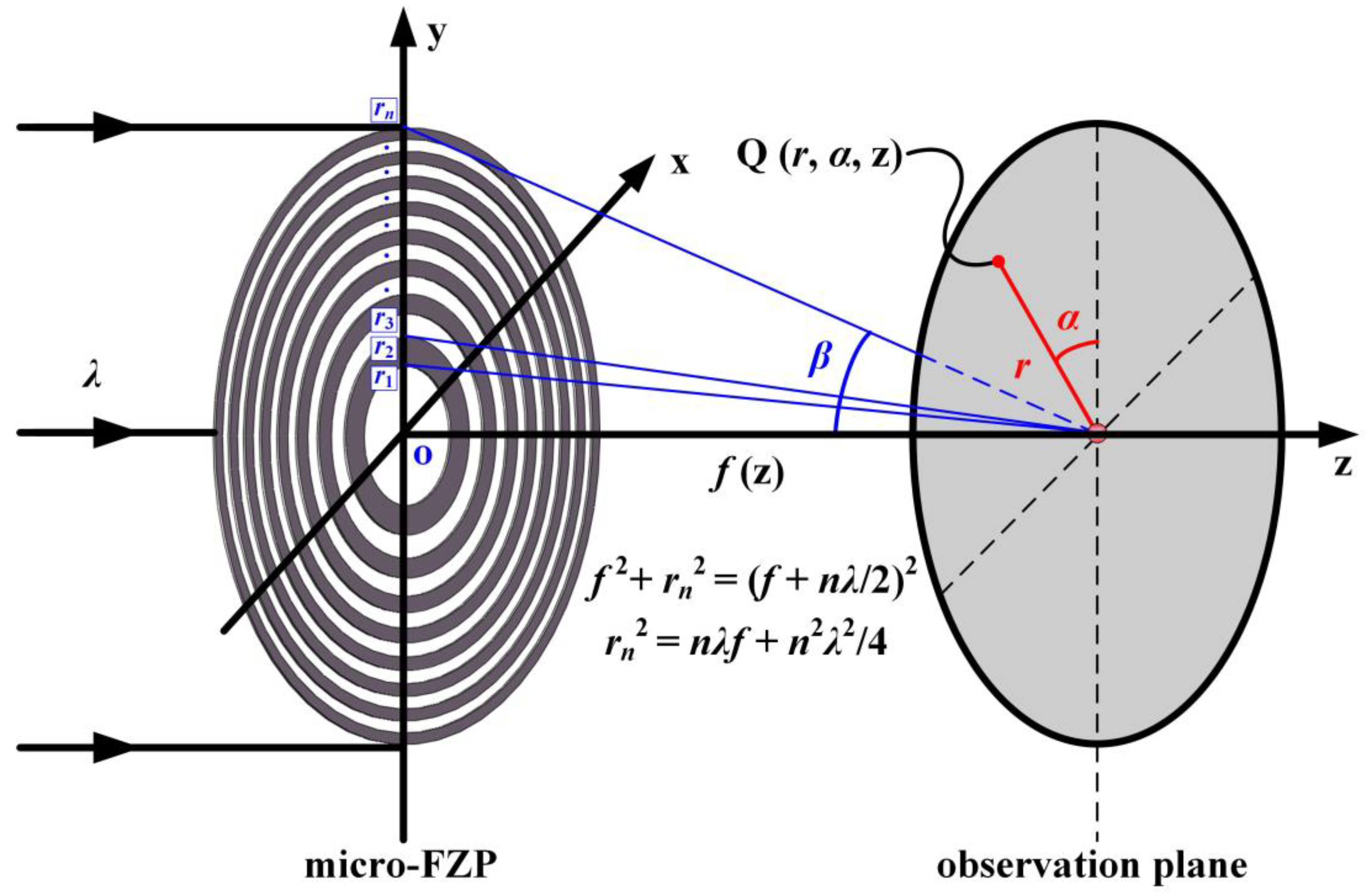
Figure 1. The focusing process of a micro-FZP.
Photonics 12 00372 g001
Figure 2. The focusing performance of the micro-FZP1 with respect to the occlusion factor k calculated using VAS and FDTD. (a) The actual focal length; (b,c) the lateral sizes of the focusing spot in x and y directions; (d) the axial size of the focusing spot.
Photonics 12 00372 g002
Figure 3. The focusing performance of the micro-FZP2 with respect to the occlusion factor k calculated using VAS and FDTD. (a) The actual focal length; (b,c) the lateral sizes of the focusing spot in x and y directions; (d) the axial size of the focusing spot.
Photonics 12 00372 g003
Figure 4. The focusing performance of the micro-FZP1 under intermittent occlusion with different rings. (a,c) The case where the 5th and 10th transparent rings are retained, while the other rings are obstructed; (b,d) the case where the 3rd and 13th transparent rings are retained, while the other rings are obstructed; (a,b) comparison of the axial focusing light intensity distributions; (c,d) the FDTD calculation results in the x-z plane.
Photonics 12 00372 g004
Figure 5. The focusing performance of the micro-FZP2 under intermittent occlusion with different rings. (a,c) The case where the 6th and 9th transparent rings are retained, while the other rings are obstructed; (b,d) the case where the 4th and 16th transparent rings are retained, while the other rings are obstructed; (a,b) comparisons of the axial focusing light intensity distributions; (c,d) the FDTD calculation results in the x-z plane.
Photonics 12 00372 g005
Figure 6. (a,b) Comparison of the results obtained when calculating the axial light field intensity distribution using VAS theory and the FDTD method for micro-FZP1 and micro-FZP2, respectively; (c,d) the light field intensity distributions for micro-FZP1 and micro-FZP2 in the x-z plane, respectively.
Photonics 12 00372 g006
Table 1. Parameters of high-NA micro-FZPs.
micro-FZPλ (nm)ηNf (μm)NA
micro-FZP16331.0 (air)4040.971
micro-FZP26331.0 (air)5090.932
Table 2. Annulus radii for the designed high-NA micro-FZP1 (unit: μm).
micro-FZP1
r1–101.6222.3382.9153.4253.8944.3364.7575.1645.5595.945
r11–206.3226.6947.0607.4227.7808.1348.4858.8349.1809.524
r21–309.86710.20710.54610.88411.22111.55611.89112.22412.55712.889
r31–4013.22013.55013.88014.20914.53714.86515.19315.52015.84716.173
Table 3. Annulus radii for the designed high-NA micro-FZP2 (unit: μm).
micro-FZP2
r1–102.4083.4344.2424.9395.5676.1476.6927.2107.7068.185
r11–208.6489.0999.5399.97010.39210.80711.21611.61912.01712.410
r21–3012.79913.18413.56613.94414.31914.69115.06115.42915.79416.158
r31–4016.51916.87817.23617.59317.94718.30118.65319.00419.35319.702
r41–5020.04920.39620.74121.08621.42921.77222.11422.45622.79623.136
Table 4. Results for micro-FZP1 with different occlusion factor k.
k00.10.20.30.40.50.60.70.8
FZ (μm)VAS4.044.184.404.585.085.506.227.468.66
FDTD4.014.164.374.665.055.716.137.579.01
FWHMx (μm)VAS0.5920.6050.6020.6000.5990.5990.6150.6190.625
FDTD0.6610.5820.5810.5800.5760.5730.5740.5820.587
FWHMy (μm)VAS0.2840.2520.2460.2440.2450.2450.2490.2550.262
FDTD0.2500.2360.2290.2260.2250.2240.2280.2360.246
FWHMz (μm)VAS0.721.422.072.593.254.034.586.267.96
FDTD0.741.432.032.533.194.004.506.348.04
Table 5. Results for micro-FZP2 with different occlusion factor k.
k00.10.20.30.40.50.60.70.8
FZ (μm)VAS9.029.069.109.209.389.6010.0211.4212.36
FDTD8.969.029.119.239.449.7110.1611.3911.99
FWHMx (μm)VAS0.5650.6160.6240.6220.6190.6180.6180.6220.626
FDTD0.5060.5520.5780.5810.5840.5850.5870.5800.564
FWHMy (μm)VAS0.3060.2760.2650.2590.2550.2540.2540.2580.262
FDTD0.2910.2620.2500.2430.2380.2370.2360.2390.242
FWHMz (μm)VAS0.861.321.782.403.314.135.257.999.57
FDTD0.881.311.802.423.304.055.047.699.16
Disclaimer/Publisher’s Note: The statements, opinions and data contained in all publications are solely those of the individual author(s) and contributor(s) and not of MDPI and/or the editor(s). MDPI and/or the editor(s) disclaim responsibility for any injury to people or property resulting from any ideas, methods, instructions or products referred to in the content.