Abstract
Bandwidth-limited transmitters have become a severe issue with the rapid growth of bandwidth-hungry services. We investigate the impact of an on-chip optical pre-emphasizer on a bandwidth-limited transmitter and quantitatively analyze the results of bandwidth extension. Improvements in eye diagram performance are discussed. The 3 dB electro-optical bandwidth of the transmission system is effectively extended from 18 GHz to 40 GHz. The extinction ratio of the on–off keying (OOK) signal at data rates of 20 to 50 Gbps is improved by 0.64–3.2 dB. Additionally, the Q factor of the eye diagram increases by 0.78–4.36 at data rates ranging from 20 to 50 Gbps.
1. Introduction
Driven by the rapid advancements in artificial intelligence, 5G communication, laser radar, and optical quantum information, internet data traffic is experiencing significant growth [1]. In order to meet this growing demand, a larger communication system capacity is required. However, due to the influence of several factors, such as bandwidth-limited transmitters, narrow-bandwidth optical filters, chromatic dispersion (CD), and the inherent fading of transmission links [2], the entire link will have bandwidth limitations, resulting in a transmission bottleneck of data capacity. The key hardware requirement for increasing data capacity is an improvement in the transmitter bandwidth. The issues of transmitter bandwidth limitation primarily arise from roll-off in the frequency response of the system, resulting in an uneven spectral distribution in which low-frequency components are disproportionately stronger while high-frequency components are weaker. The transmitter bandwidth can be increased by reasonably designing the modulator parameters to boost the high-frequency components. The concept of frequency response control has also been explored in other optical design contexts [3,4]. In terms of modulator design, there are the following three main concerns: optical loss, modulation efficiency, and electro-optical bandwidth. These three parameters are interdependent, affecting the modulator output and the signal quality [5]. By reducing the length of the phase shifter, it is possible to reduce optical losses and increase the modulator bandwidth, but the modulation depth will be influenced. Due to design mismatch and processing errors, it is difficult to meet all design requirements. The solution to the above problem is to introduce compensation technology.
Extensive research has been conducted on compensation techniques, including a range of electrical and optical schemes [6,7]. These schemes are typically categorized based on their placement—digital pre-emphasis (before the Digital-to-Analog Converter (DAC)), analog pre-emphasis (after the DAC), and optical pre-emphasis (after the modulator) at the transceiver-side and optical equalization (before the photodetector (PD)) and digital equalization (after PD) at the receiver-side. Electrical domain compensation typically compensates for the DAC, Radio-Frequency (RF) amplifier, and CD effects. In practical use, digital signal processing schemes are relatively complex, require advanced manufacturing processes, and consume higher power [8,9]. In [10], the transmission of 105 Gbaud dual-polarization 64 quadrature amplitude modulation was demonstrated using a silicon photonic in-phase/quadrature modulator (IQM) and all-electronic equalization over 80 km, corresponding to a record-breaking net rate of 1 Tbps. The frequency response of the chain was compensated for in the electrical domain using digital filters, taking into account the combined frequency response effects of the arbitrary waveform generator, RF amplifiers and cables at the transmitter, and the combined frequency response effects of the probe, IQM, and photodiode at the receiver. However, digital pre-emphasis essentially reduces the amplitude of the signal’s low-frequency components to achieve a flat frequency response. This inevitably increases the quantization error and reduces the overall signal-to-noise ratio (SNR), thereby restricting the use of high-order modulation formats and low-overhead forward error correction required in communication systems. To mitigate the SNR degradation caused by quantization errors, analog pre-emphasis can be combined with digital pre-emphasis to achieve an optimized system performance [11]. The relationship between pre-emphasis-induced SNR degradation and frequency response flatness was also analyzed through different analog filter designs. The adopted analog passive pre-emphasis circuit had low insertion loss, but was limited by the device bandwidth, making it unsuitable for broadband optical systems. In the equalization of dispersion-limited transmission, reducing the number of taps per symbol by applying the clustering algorithm was implemented, still using a decision-feedback equalizer with a >100-tap feedback filter [12]. However, the complexity was still too high. With the introduction of a single-tap optical delay line and a 39-tap symbol-spaced digital feed-forward equalizer at the receiver side, the CD-induced deep frequency notches could be well compensated, achieving a reduction in both the complexity and power consumption of the subsequent digital equalizer [13].
Optical domain compensation typically compensates for CD effects and modulator bandwidth. Compared with electrical compensation, optical compensation technology, especially optical compensation using integrated devices, usually offers the advantages of a compact size, low cost, low power consumption, high tunability, high reconfigurability, and wide compensation range [14]. Enhancing the bandwidth response performance of optical devices by hybrid-polar dielectric materials and algorithm-optimized metasurface structures has also been explored [15,16]. An optical transmission network is an important part of optical communication. Previous research on optical compensation has focused on CD compensation. To date, several types of CD equalizers, including CD compensating fibers [17], chirped Bragg gratings [18], Mach–Zehnder interferometers (MZIs) [19,20,21], and microring resonators (MRRs) [22,23], have been reported to effectively mitigate the effects of CD. A low-loss optical equalizer is proposed to compensate for linear dispersion in short-reach coherent interconnects, greatly improving the overall power efficiency of receivers [21]. Currently, the optical layer is evolving from a pure transmission layer to a real networking layer capable of providing end-to-end network services [24]. Therefore, the demand for optical compensation is increasing. An on-chip filter was reported to extend modulator bandwidth, thereby improving the bit error rate and SNR. One such example is an optical equalizer monolithically integrated with a silicon IOM, which aims to increase the modulation bandwidth, thereby alleviating the design contradiction between low-voltage drive and high bandwidth. The integrated equalizer consists of two cascaded MZIs, each with relative optical path delay and two 2 × 2 tunable couplers [2]. The extinction ratio and center wavelength of the equalizer are tunable, with a free spectral range (FSR) of 0.55 nm. By introducing the optical equalizer, the modulator can generate a 56 Gbaud orthogonal phase-shift keying signal and the optical SNR is improved by 2.5 dB at a bit error rate of 2.4 × 10⁻². But there is a lack of quantitative analysis on the bandwidth extension results. In addition, a multifunctional mixed analog/digital signal processor of cascaded MRRs and delay line architectures (CMRR-DL) has been demonstrated for electro-optical bandwidth equalization [25]. The bandwidth extension and Q-value improvement highlight the effectiveness of the on-chip equalizer in improving signal quality. CMRR-DL can be used for multi-dimensional optical operations, including wavelength selection, amplitude adjustment, and time delay. Individual MRRs can be precisely tuned by adjusting the voltage applied to the corresponding microheater, but reshaping of the spectral shape based on a single or cascaded MRR structure is limited. Highly tunable optical pre-compensation is required, because the frequency response of the modulator will change with different operating points. In system-oriented research, optimizing performance typically requires a combination of methods, as relying on a single approach may not yield optimal results [26], and intelligent design strategies have also been introduced to further enhance system adaptability [27].
In this work, we investigate the impact of on-chip optical pre-emphasis on a bandwidth-limited transmitter, quantitatively analyze the results of bandwidth extension experiments, and discuss improvements in eye diagram performance. Bandwidth extension experiments were performed using a silicon-based integrated optical filter and a commercial LiNbO3 modulator (iXblue MXAN-LN-20) with a limited ~20 GHz electro-optical bandwidth. The optical pre-emphasis filter was composed of a cascaded dual-ring-assisted MZI (DR_MZI), constructing an optical infinite impulse response (IIR) filter. On-chip filters potentially offer performance enhancements with their simple and compact structure, large FSR, and strong spectral reshaping capabilities, and are well-suited for densely integrated high-bandwidth optical transceivers. By attenuating low-frequency components, the pre-emphasis filter significantly extended the bandwidth of the transmission system from 18 GHz to 40 GHz. A comparative analysis of eye diagrams for 10–50 Gbps OOK signals in back-to-back transmission showed that pre-emphasis substantially improved the communication quality of bandwidth-limited transmitters.
2. Optical Pre-Equalization Filter
In this section, the structures and transfer functions of the pre-equalizers are introduced. The spectral performance of the filters is experimentally studied to preliminarily determine the initial voltage matrix of each phase shifter corresponding to the filter roll-off suitable for pre-compensation.
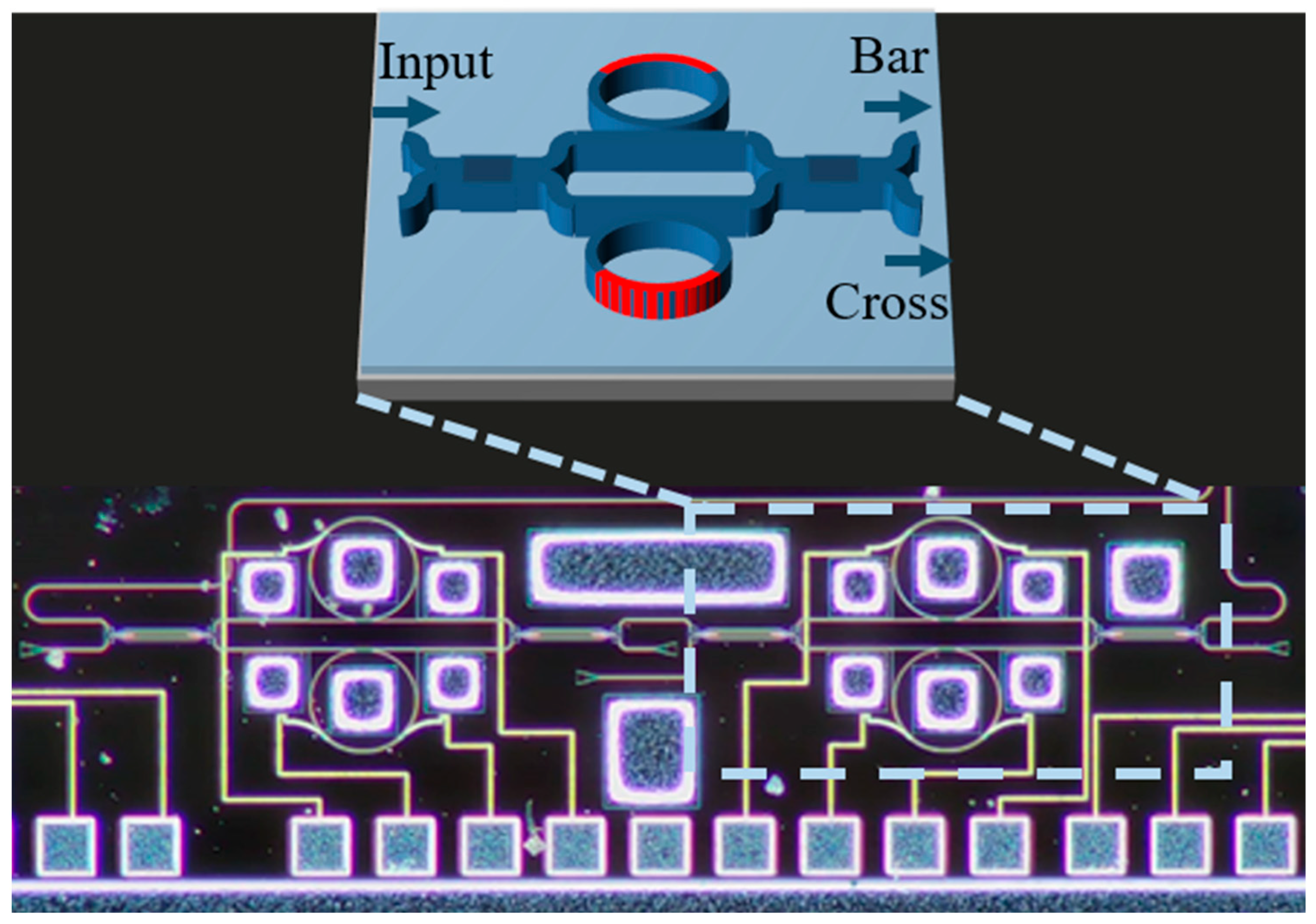
Figure 1 shows a schematic diagram of our optical pre-emphasis filter. The IIR filter unit utilizes a DR-MZI structure. The input signal is divided using a multimode interference (MMI) coupler, with each optical coupled to the adjustable micro-ring resonators situated on the upper and lower arms of the balanced MZI. In the ideal initial state, the two identical MRRs align in resonant wavelength, producing identical phase responses in their coupled waveguides. As a result, the phase difference between the upper and lower modulation arms is zero. According to the interference principle of the MZI, under these conditions, all optical signals are predominantly directed to the cross port (minimizing losses), while both the cross port and bar port exhibit nearly flat spectral responses. This configuration corresponds to the ‘cross’ state of the DR-MZI. By applying a voltage to the heater on one of the MRRs, the resonance wavelength shifts, introducing a phase difference between the upper and lower MZI arms. This change results in deep notches at the cross port and peaks at the bar port near the resonance wavelengths. When the phase difference reaches π, the optical signals close to the resonant wavelength are primarily redirected to the bar port, switching the DR-MZI to the ‘bar’ state. To achieve a bandpass filter, we select the bar port for cascading. In the DR-MZI, the MRRs are designed to operate in the overcoupled mode, broadening the bandwidth of the filter. Moreover, significant phase changes in the waveguide near the resonance wavelength are beneficial for reducing power consumption. The structure is monolithically integrated onto a 220 nm silicon-on-insulator (SOI) wafer. The effect of micro-ring coupling on the extinction ratio is no more than 3.5 dB within a ± 30 nm processing error. The thermo-optic phase shifters in this work are all made of TiN thermal resistors. In fact, the DR-MZI works as a second-order optical add-drop filter. Therefore, the demonstrated equalizer is a fourth-order optical filter.
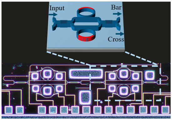
Figure 1.
Schematic diagram of fourth-order optical pre-emphasis filter.
The transfer matrix for the DR-MZI is as follows:
Thus, the transfer function of the 4th-order IIR filter is as follows:
where denotes the electric field response at the input port and represent the electric field responses at the “bar”/“cross” output ports, respectively. The parameters and are the coupling and transmission coefficients of the 2 × 2 MMI. For an ideal 50:50 MMI splitter, . The transfer function of the MRR and MZI coupling arms are ( = 1, 2, 3, and 4).
- where
Here, is the optical field amplitude coupling coefficient between the MZI arm and the micro-ring waveguide and is the amplitude decay factor for light traveling in the micro-ring resonator. The phase change accumulates by light traveling around the micro-ring, and the round-trip phase shift can be interpreted as , with and representing the phase shifts introduced by thermal phase shifters on the ring. is the effective refractive index of the optical mode, is the vacuum wavelength of the incident light, and is the circumference of the micro-ring.
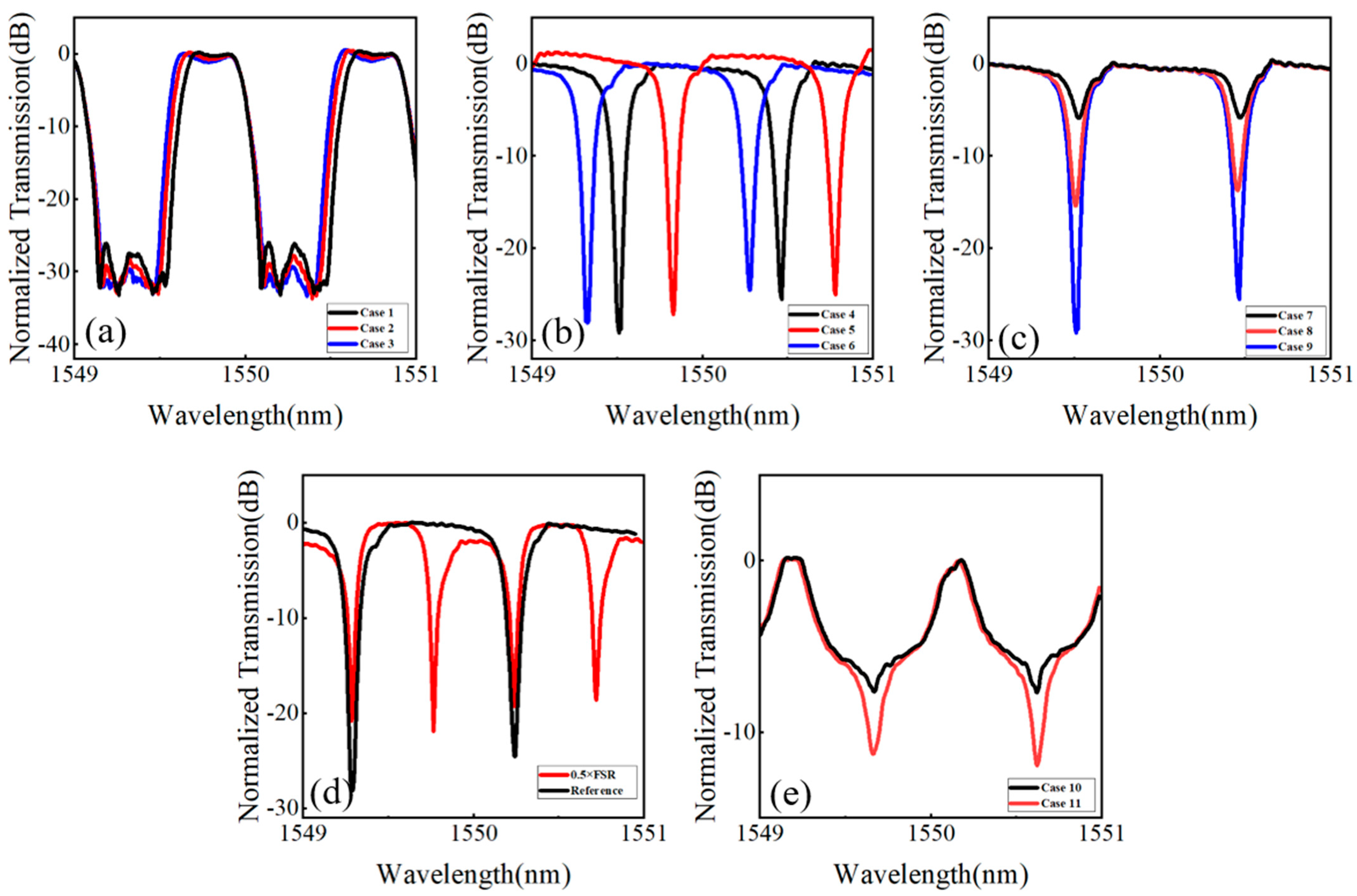
The experimental results of tuning the center wavelength, bandwidth, out-of-band suppression, and filtering shape of the fourth-order IIR optical filter are presented in Figure 2. This tuning was achieved by controlling the phase shifter on the IIR filter micro-ring. The transmitted spectra with tunable optical bandwidths are illustrated in Figure 2a. Case 1, Case 2, and Case 3 exhibit 3 dB bandwidths of 0.32 nm, 0.365 nm, and 0.395 nm, respectively, indicating that the maximum variation in the 3 dB bandwidth is approximately 0.075 nm. Figure 2b depicts the transmitted spectra with a tunable center wavelength. The tuning range of the center wavelength can cover the entire FSR. Figure 2c presents the transmitted spectra with a tunable out-of-band suppression ratio. Case 7, Case 8, and Case 9 demonstrate suppression ratios of 6 dB, 14 dB, and 25 dB, respectively, indicating a tuning range of 19 dB. The spectra depicted in Figure 2d show that the wavelength spacings between two adjacent dip peaks within a single FSR of the red curve are approximately half of the black curve. The device is reconfigured into two filters with different FSRs. Figure 2e depicts the two filtered spectra with relatively smooth roll-offs, suitable for pre-equalization.
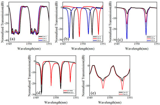
Figure 2.
Measured transfer spectra for 4th-order IIR filter: (a–c) measured the spectra of central wavelength, bandwidth, and extinction ratio tunability; (d) the FSR is reduced to one-half; and (e) measured the spectra with relatively smooth roll-offs.
3. Experimental Setup
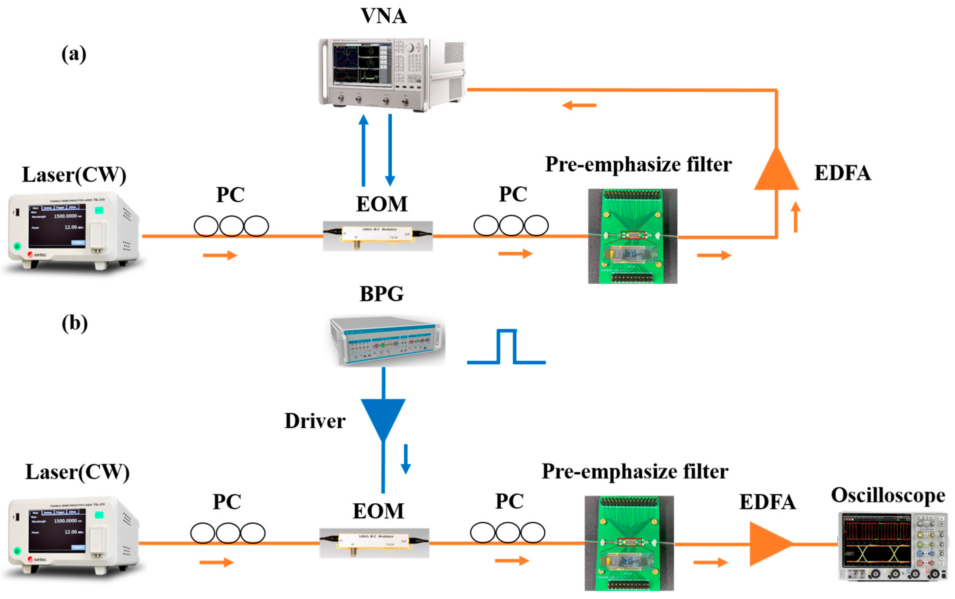
The experimental setup is shown in Figure 3. We use a vector network analyzer (VNA) (Keysight PNA-X Network Analyzer, Keysight Technologies, Santa Rosa, CA, USA) and a LiNbO3 Mach–Zehnder modulator (MZM) with a 3 dB bandwidth of 20 GHz to estimate the frequency equalization properties of the on-chip filter, as shown in Figure 3a. S parameters are collected with and without the filter. In Figure 3b, the output of a continuous-wave (CW) laser (Santec Tunable Semiconductor Laser TSL-570, Santec Corporation, Aichi, Japan) is modulated by the LiNbO3 MZM using the outputs of a binary pattern generator (BPG) (SHF 12104 A Bit Pattern Generator, SHF Communication Technologies AG, Berlin, Germany), which provides various long pseudo-random binary sequences (PRBSs). The OOK signal at the output of the MZM passes through the optical pre-emphasis filter and is then amplified by an optical fiber amplifier (EDFA) (Amonics AEDFA-PA-35-B-FA, SHF Communication Technologies AG, Berlin, Germany). We record the signals using a digital sampling oscilloscope and perform offline signal analysis. Placing an optical filter after the modulator can extend the transmitter bandwidth by adjusting the spectral response around the carrier wavelength, which effectively constructs an inverse system to pre-compensate for the roll-off of the modulator frequency response.
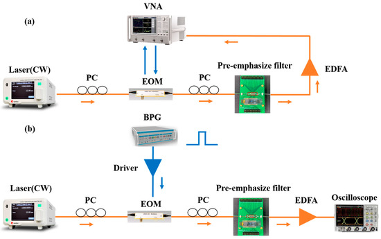
Figure 3.
The experimental setup for (a) 3 dB electro-optical bandwidth measurement and (b) OOK signal transmission.
4. Discussion and Results
In this section, we illustrate the contribution of pre-compensation to modulator bandwidth limitation through VNA-measured S21 parameters. Eye diagrams of back-to-back transmissions are then analyzed to show the reduction in signal impairments. In the pre-emphasis experiment, the voltage applied to a thermal phase shifter is initially adjusted, followed by fine-tuning the laser output wavelength until the frequency response of the modulator is flattened.
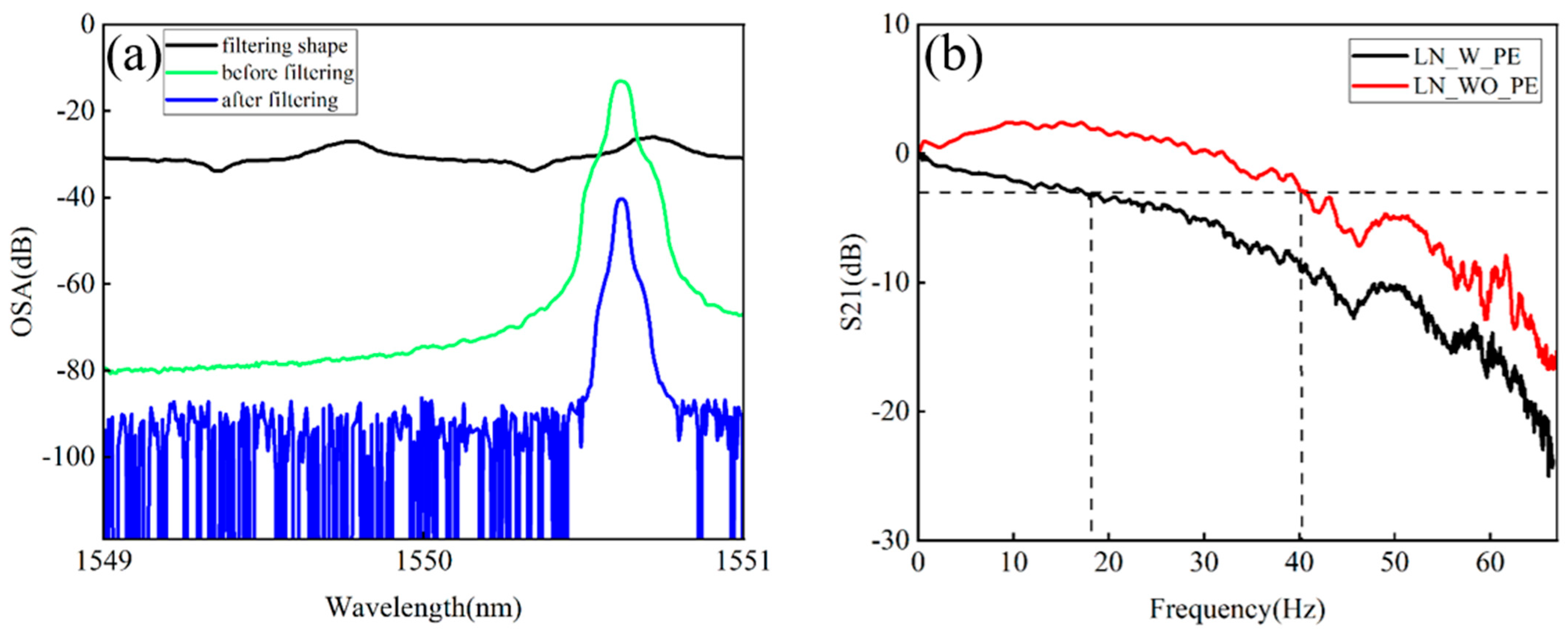
The MRRs in the IIR filter have a radius of 90 μm, corresponding to an FSR of 0.94 nm. The final IIR filter waveform is depicted in Figure 4a. Assume that the applied voltage array is , where , , , and are the voltages applied to the first-stage DRR-MZI upper arm, the first-stage DR-MZI lower arm, the second-stage DRR-MZI upper arm, and the second-stage DR-MZI lower arm, respectively. The current limit is 0.01 A. In the equalizer waveform shown in Figure 4a, the voltage array is set as . Figure 4b compares the effect of the optical IIR pre-equalizer on the frequency response of the transmission system. The introduction of the optical pre-equalizer increases the 3 dB electro-optical bandwidth of the transmitter from 18 GHz to 40 GHz. Additionally, the pre-emphasis frequency response (red curve) is notably flatter, significantly improving the overall system performance.
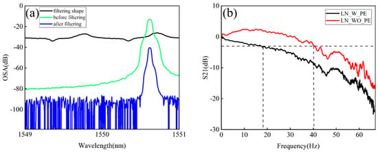
Figure 4.
On-chip IIR pre-emphasis bandwidth extension results: (a) pre-emphasis waveform applied and (b) measured S21 before and after pre-emphasis.
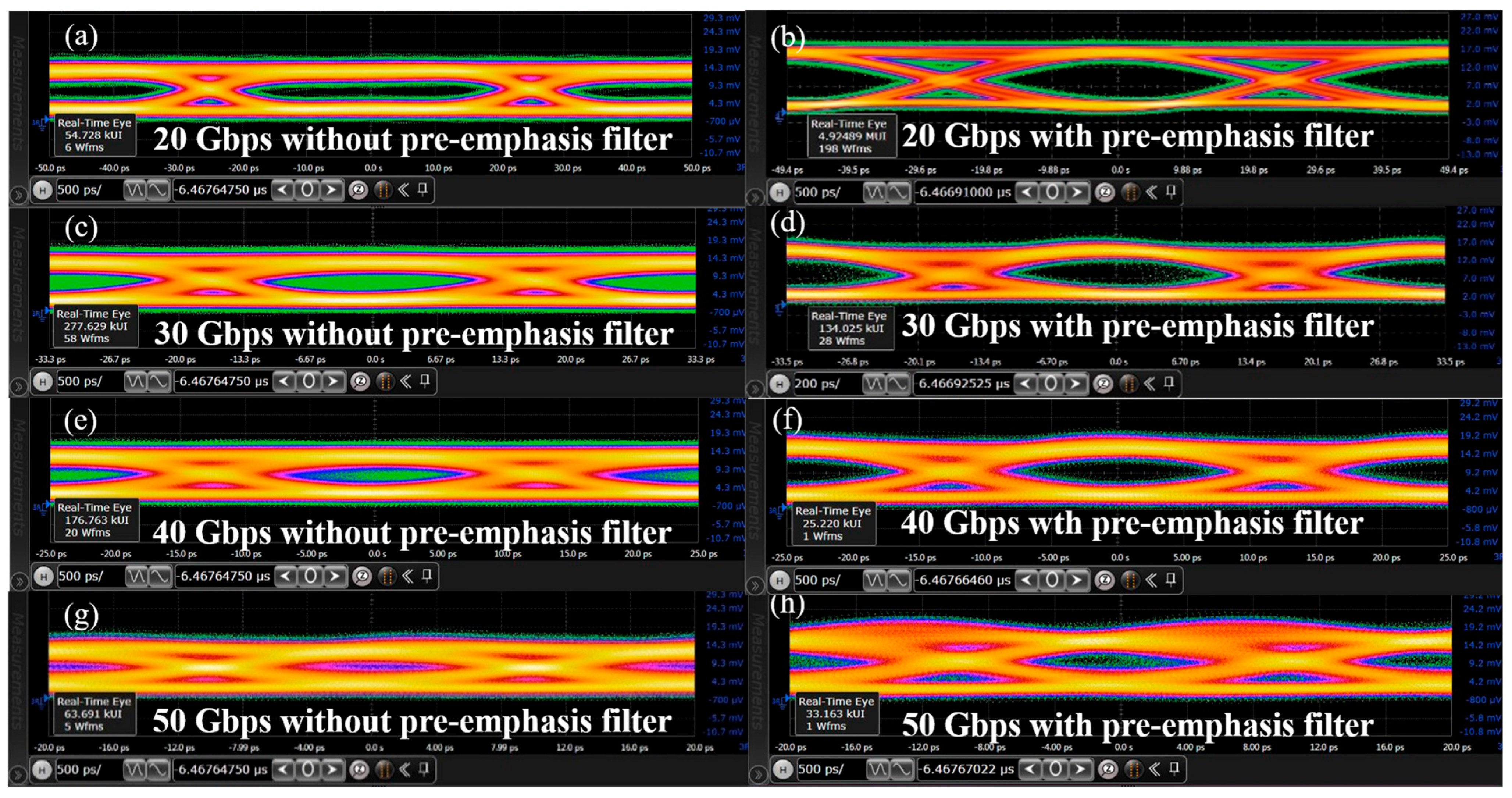
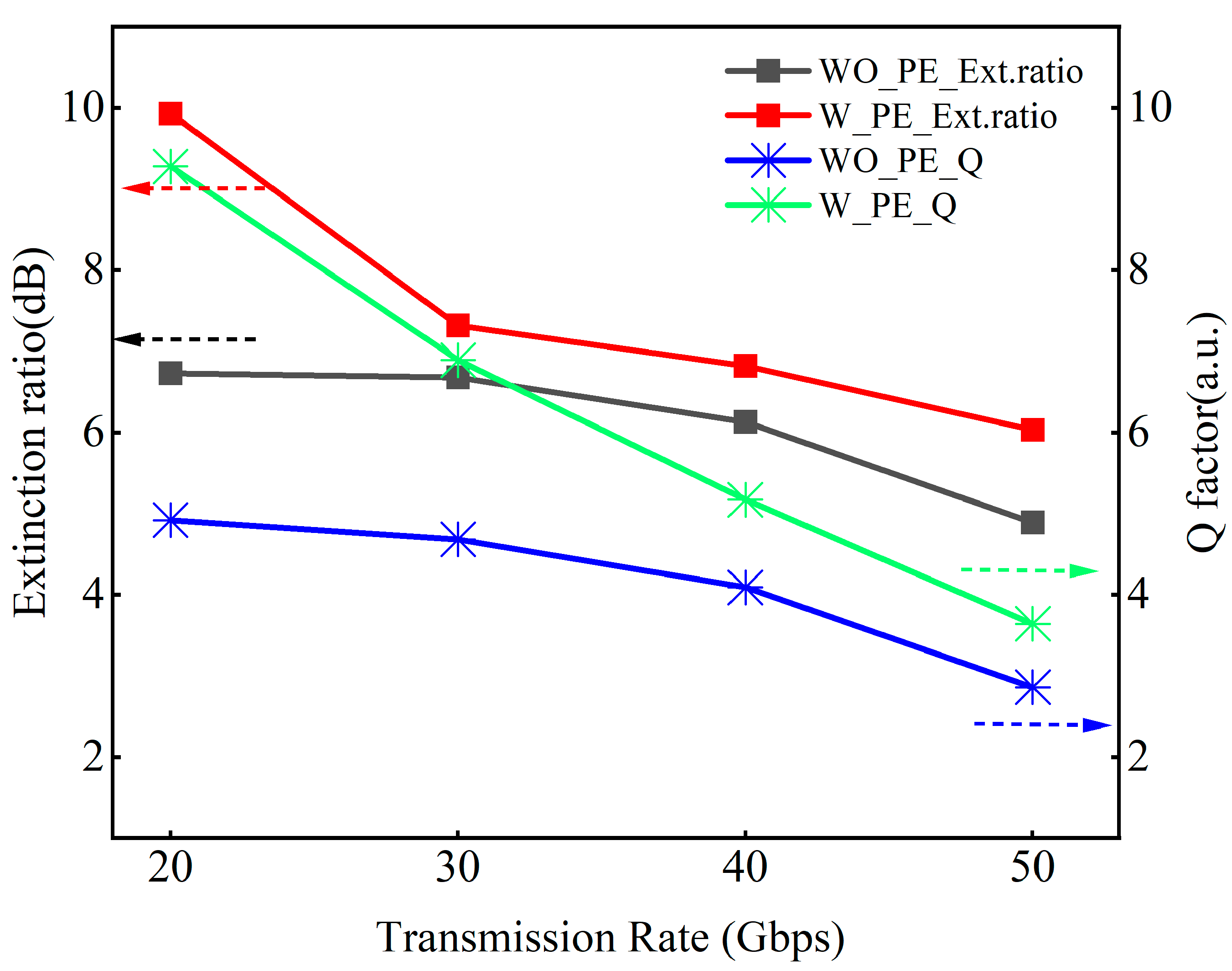
In order to investigate the effect of the introduced on-chip optical IIR filter on signals with different data rates, the eye diagrams of OOK signals at data rates of 20, 30, 40, and 50 Gbps are measured. The same study is also conducted for the input OOK optical signal without optical pre-emphasis. As can be seen in Figure 5, a clearer eye diagram is obtained and the signal distortion is suppressed. It can also be observed that the signal quality is improved due to optical IIR pre-emphasis. To further evaluate the performance of the method used, Figure 6 quantifies this improvement, showing the extinction ratio and Q-factor analysis of the eye diagram. The effect is particularly significant at low transmission rates. At a transmission rate of 20 Gbps, the OOK signal demonstrates a significant improvement in extinction ratio of approximately 3.2 dB, while the Q factor of the eye diagram increases by approximately 4.36. At a data rate of 30 Gbps, the extinction ratio of the OOK signal is improved by nearly 0.64 dB and the Q factor of the eye diagram is increased by about 2.21. At 40 Gbps, the extinction ratio increases by approximately 0.69 dB and the Q factor rises by about 1.08. At 50 Gbps, the extinction ratio improves by about 1.14 dB, with the Q factor increasing by nearly 0.78. These results collectively demonstrate the effectiveness of the proposed approach across a wide range of data rates.
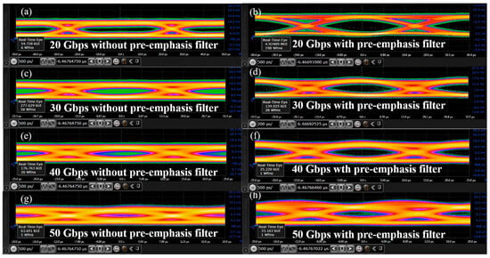
Figure 5.
Eye diagram measurement results: (a,c,e,g) show the eye diagrams of OOK signals at 20 Gbps, 30 Gbps, 40 Gbps, and 50 Gbps without IIR pre-emphasis, respectively; (b,d,f,h) show the eye diagrams of OOK signals at 20 Gbps, 30 Gbps, 40 Gbps, and 50 Gbps with IIR pre-emphasis, respectively.
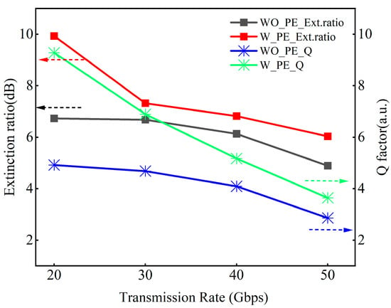
Figure 6.
Extinction ratio and Q factor with and without IIR pre-emphasis at transmission rates of 20 Gbps to 50 Gbps.
Improvements in modulator bandwidth are instrumental for optical communications. Pre-emphasis is a method that goes hand in hand with modulator design to extend transmitter bandwidth. Our results demonstrate that pre-emphasis can effectively mitigate impairments, resulting in a substantial enhancement in performance. The improvement in communication quality is attributed to the fact that pre-emphasis changes the frequency response of the transmitter, making it more uniform and increasing the transmitter bandwidth.
When the filter acts as an equalizer, an inverse system is constructed through the rising edge to compensate for the roll-off of the modulator frequency response. Unlike the step-like rising and falling edges expected in an ideal filter, the frequency response of the pre-equalization filter needs to have a smooth roll-off, and the slope and shape of the roll-off are preferably adjustable to meet the compensation requirements of different modulators. Photonic tunable filters have great advantages in simplicity and flexibility. MRRs are compact and highly versatile, offering wavelength selectivity due to their resonant properties; however, their response follows a Lorentzian curve, limiting their operational bandwidth. To achieve a box-like spectral response, multi-ring cascading structures are commonly employed, requiring the precise design of each MRR’s size. A single-stage MZI optical filter produces a sinusoidal spectral response with inherent wavelength selectivity, which can be improved through cascading to achieve a flat-top response. MZIs offer broader spectral responses, easy tunability, and resilience to external thermal crosstalk. The interference path of the MZI structure is pure feedforward, with no feedback loop. As a result, achieving high out-of-band suppression requires higher filter orders. However, the cascaded nature of these devices leads to increased losses as the filter order grows. The DR-MZI structure combines the advantages of both MRRs and MZIs, delivering a compact form factor, low power consumption, high extinction ratio, and good spectral reshaping properties. The equalizer frequency response can be flexibly adjusted to suit different modulation formats. The FSR of the filter is adjustable to meet the needs of a variety of pre-emphasis scenarios. In contrast, IIR filters incorporate feedback loops, enabling them to achieve the same stopband suppression with fewer stages compared to finite impulse response filters. Note that the spectrum of the filter is periodic. The period of the IIR filter is inversely proportional to the length of the MRR. Since the micro-ring lengths of on-chip filters can be very small, the equalization range can be further expanded. The filters used have flat passbands and large stopband rejections, enabling a higher data transmission capacity, potentially lower cost, and power-efficient solution. In addition, on-chip equalizers can also be integrated with the transmitter monolithically to support the processing and reshaping of broadband modulated signals in a highly integrated form.
The improvement in communication quality comes at the expense of excess optical loss due to the optical emphasis of the high-frequency component essentially attenuating the magnitude of the low-frequency components in the optical domain. This attenuation adds to the insertion loss of the system, which has almost 14 dB coupling losses, with the filter insertion losses being around 7 dB, where monolithic integration with transmitter would avoid additional coupling losses.
5. Conclusions
We demonstrate an on-chip optical pre-equalizer on the SOI platform. Through a process of tuning the transfer function of the filter, the pre-emphasis filter significantly extends the bandwidth of the transmission system from 18 GHz to 40 GHz. The use of the pre-emphasis filter leads to substantial eye-opening improvements for strong bandwidth-limited signals. We indicate this potential using 20, 30, 40, and 50 Gbps OOK signals. It is also possible to extend the filter order for a higher pre-emphasis potential, but at the expense of a higher filter complexity and higher insertion loss. On-chip optical pre-equalization is a promising and perhaps necessary solution path to improve the performance of bandwidth-limited transmitters for compact or range-flexible deployments. It may further reduce DSP complexity and power consumption, decrease the need for a high-end DAC, and lay the foundation for a joint optimization strategy.
Author Contributions
Conceptualization, T.L. and H.S.; methodology, T.L. and H.S.; validation, T.L., Y.L., L.X., Z.G. and S.L.; writing—original draft preparation, Y.L.; writing—review and editing, T.L., H.S., D.H., Z.H. and H.D.; funding acquisition, T.L., H.S. and D.H. All authors have read and agreed to the published version of the manuscript.
Funding
This research was funded by the National Key Research and Development Program of China (2022YFB2903201), the National Natural Science Foundation of China (62105260, 62322501, 12204021), Young Talent fund of University Association for Science and Technology in Shaanxi, China (20220135).
Institutional Review Board Statement
Not applicable.
Informed Consent Statement
Not applicable.
Data Availability Statement
Data are contained within the article.
Conflicts of Interest
The authors declare no conflicts of interest.
References
- Shi, W.; Tian, Y.; Gervais, A. Scaling capacity of fiber-optic transmission systems via silicon photonics. Nanophotonics 2020, 9, 4629–4663. [Google Scholar] [CrossRef]
- Dong, P.; Xie, C.; Buhl, L.L.; Chen, Y.-K.; Sinsky, J.H.; Raybon, G. Silicon in-phase/quadrature modulator with on-chip optical equalizer. J. Light. Technol. 2015, 33, 1191–1196. [Google Scholar] [CrossRef]
- Jing, X.; Gui, X.; Zhou, P.; Hong, Z. Physical explanation of Fabry–Pérot cavity for broadband bilayer metamaterials polarization converter. J. Light. Technol. 2018, 36, 2322–2327. [Google Scholar] [CrossRef]
- Nan, T.; Zhao, H.; Guo, J.; Wang, X.; Tian, H.; Zhang, Y. Generation of structured light beams with polarization variation along arbitrary spatial trajectories using tri-layer metasurfaces. Opto-Electron. Sci. 2024, 3, 230052. [Google Scholar] [CrossRef]
- Sepehrian, H.; Lin, J.; Rusch, L.A.; Shi, W. Silicon photonic IQ modulators for 400 Gb/s and beyond. J. Light. Technol. 2019, 37, 3078–3086. [Google Scholar] [CrossRef]
- Silva, L.C.; Marciano, P.R.; Pontes, M.J.; Monteiro, M.E.; André, P.S.; Segatto, M.E. Integrated Photonic Neural Networks for Equalizing Optical Communication Signals: A Review. Photonics 2025, 12, 39. [Google Scholar] [CrossRef]
- Van Assche, R.; Masaad, S.; Gooskens, E.; Sackesyn, S.; Van Kerrebrouck, J.; Yin, X.; Bienstman, P. Real-time all-optical signal equalisation with silicon photonic recurrent neural networks. arXiv 2025, arXiv:2503.19911. [Google Scholar]
- Kaneda, N.; Lee, J.; Chen, Y.-K. Nonlinear equalizer for 112-Gb/s SSB-PAM4 in 80-km dispersion uncompensated link. In Proceedings of the Optical Fiber Communication Conference, Los Angeles, CA, USA, 19–23 March 2017; Optica Publishing Group: Washington, DC, USA, 2017; p. 2. [Google Scholar]
- Wang, H.; Zhou, J.; Guo, D.; Feng, Y.-H.; Liu, W.; Yu, C.; Li, Z. Adaptive channel-matched detection for C-band 64-Gbit/s optical OOK system over 100-km dispersion-uncompensated link. J. Light. Technol. 2020, 38, 5048–5055. [Google Scholar] [CrossRef]
- Berikaa, E.; Alam, S.; Plant, D.V. Silicon photonic modulators for net 300 Gbps/λ IM/DD and Net 1 Tbps/λ coherent transmission using All-Electronic equalization. Opt. Fiber Technol. 2022, 74, 103056. [Google Scholar] [CrossRef]
- Zhou, Z.; Odedeyi, T.; Kelly, B.; O’Carroll, J.; Phelan, R.; Darwazeh, I.; Liu, Z. Impact of analog and digital pre-emphasis on the signal-to-noise ratio of bandwidth-limited optical transceivers. IEEE Photonics J. 2020, 12, 7200712. [Google Scholar] [CrossRef]
- Wu, X.; Zhang, J.; Lau, A.P.T.; Lu, C. Low-complexity absolute-term based nonlinear equalizer with weight sharing for C-band 85-GBaud OOK transmission over a 100-km SSMF. Opt. Lett. 2022, 47, 1565–1568. [Google Scholar] [CrossRef]
- Zhu, P.; Yoshida, Y.; Kanno, A.; Kitayama, K.-I. Analysis and demonstration of low-complexity joint optical-electrical feedforward equalization (OE-FFE) for dispersion-limited high-speed IM/DD transmission. J. Light. Technol. 2022, 41, 477–488. [Google Scholar] [CrossRef]
- Shekhar, S.; Bogaerts, W.; Chrostowski, L.; Bowers, J.E.; Hochberg, M.; Soref, R.; Shastri, B.J. Roadmapping the next generation of silicon photonics. Nat. Commun. 2024, 15, 751. [Google Scholar] [CrossRef]
- Zhang, Y.; Chen, Y.; Wang, T.; Zhu, Q.; Gu, M. Ultrahigh performance passive radiative cooling by hybrid polar dielectric metasurface thermal emitters. Opto-Electron. Adv. 2024, 7, 230194. [Google Scholar] [CrossRef]
- Yu, Z.; Li, M.; Xing, Z.; Gao, H.; Liu, Z.; Pu, S.; Mao, H.; Cai, H.; Ma, Q.; Ren, W.; et al. Genetic algorithm assisted meta-atom design for high-performance metasurface optics. Opto-Electron. Sci. 2024, 3, 240016. [Google Scholar] [CrossRef]
- Grüner-Nielsen, L.; Wandel, M.; Kristensen, P.; Jorgensen, C.; Jorgensen, L.V.; Edvold, B.; Pálsdóttir, B.; Jakobsen, D. Dispersion-compensating fibers. J. Light. Technol. 2005, 23, 3566. [Google Scholar] [CrossRef]
- Liu, Y.; Zhang, H.; Liu, J.; Lu, L.; Du, J.; Li, Y.; He, Z.; Chen, J.; Zhou, L.; Poon, A.W. Parallel wavelength-division-multiplexed signal transmission and dispersion compensation enabled by soliton microcombs and microrings. Nat. Commun. 2024, 15, 3645. [Google Scholar] [CrossRef]
- Moreira, R.; Gundavarapu, S.; Blumenthal, D.J. Programmable eye-opener lattice filter for multi-channel dispersion compensation using an integrated compact low-loss silicon nitride platform. Opt. Express 2016, 24, 16732–16742. [Google Scholar] [CrossRef]
- Brodnik, G.M.; Pinho, C.; Chang, F.; Blumenthal, D.J. Extended reach 40km transmission of C-band real-time 53.125 Gbps PAM-4 enabled with a photonic integrated tunable lattice filter dispersion compensator. In Proceedings of the 2018 Optical Fiber Communications Conference and Exposition (OFC), San Diego, CA, USA, 11–15 March 2018; IEEE: Piscataway, NJ, USA, 2018; pp. 1–3. [Google Scholar]
- Sidhique, A.; Karmakar, S.; Chugh, S.; Gupta, S. Adaptive electro-optic equalization in low-power coherent-lite interconnects. Appl. Opt. 2023, 62, 8411–8415. [Google Scholar] [CrossRef]
- Madsen, C.; Lenz, G.; Bruce, A.; Cappuzzo, M.; Gomez, L.; Nielsen, T.; Adams, L.; Brenner, I. An all-pass filter dispersion compensator using planar waveguide ring resonators. In Proceedings of the OFC/IOOC. Technical Digest. Optical Fiber Communication Conference, 1999, and the International Con-ference on Integrated Optics and Optical Fiber Communication, San Diego, CA, USA, 21–26 February 1999; Optica Publishing Group: Washington, DC, USA, 1999; p. FE6. [Google Scholar]
- Liu, Y.; Lu, L.; Ni, Z.; Chen, J.; Chen, J.; Zhou, L. Silicon integrated continuously tunable dispersion compensator based on cascaded micro-ring resonators. In Proceedings of the 2022 Asia Communications and Photonics Conference (ACP), Shenzhen, China, 5–8 November 2022; IEEE: Piscataway, NJ, USA, 2022; pp. 1352–1355. [Google Scholar]
- Secondini, M.; Forestieri, E.; Prati, G. Performance of MSE configured PLC optical equalizers for chromatic dispersion compensation. IEEE Photonics Technol. Lett. 2003, 15, 248–250. [Google Scholar] [CrossRef]
- Wu, Y.; Yang, Q.; Shen, B.; Tao, Y.; Zhang, X.; Tao, Z.; Xing, L.; Ge, Z.; Li, T.; Bai, B.; et al. Multifunctional mixed analog/digital signal processor based on integrated photonics. Opto-Electron. Sci. 2024, 3, 240012. [Google Scholar] [CrossRef]
- Lin, J.; Sepehrian, H.; Rusch, L.A.; Shi, W. Single-carrier 72 GBaud 32QAM and 84 GBaud 16QAM transmission using a SiP IQ modulator with joint digital-optical pre-compensation. Opt. Express 2019, 27, 5610–5619. [Google Scholar] [CrossRef]
- Zhang, S.; Li, H.; Fan, C.; Zeng, Z.; Xiong, C.; Wu, J.; Yan, Z.; Liu, D.; Sun, Q. Adaptive decentralized AI scheme for signal recognition of distributed sensor systems. Opto-Electron. Adv. 2024, 7, 240119. [Google Scholar] [CrossRef]
Disclaimer/Publisher’s Note: The statements, opinions and data contained in all publications are solely those of the individual author(s) and contributor(s) and not of MDPI and/or the editor(s). MDPI and/or the editor(s) disclaim responsibility for any injury to people or property resulting from any ideas, methods, instructions or products referred to in the content. |
© 2025 by the authors. Licensee MDPI, Basel, Switzerland. This article is an open access article distributed under the terms and conditions of the Creative Commons Attribution (CC BY) license (https://creativecommons.org/licenses/by/4.0/).

