On-Chip Guiding of Higher-Order Orbital Angular Momentum Modes


Department of Electrical and Computer Engineering, Ajou University, Suwon 16499, Korea
*
Author to whom correspondence should be addressed.
Photonics 2019, 6(2), 72; https://doi.org/10.3390/photonics6020072
Submission received: 22 May 2019
/
Revised: 18 June 2019
/
Accepted: 20 June 2019
/
Published: 23 June 2019
(This article belongs to the Special Issue Optical Angular Momentum in Nanophotonics II)
Abstract
:Higher-order orbital angular momentum (OAM) mode guiding in a waveguide which is suitable for on-chip integration has been investigated. Based on the relation between the Laguerre-Gaussian mode and the Hermite-Gaussian mode, it has been shown that two degenerate guided modes of π/2l-rotation symmetry can support the l-th order OAM mode. In order to mimic the rotational symmetry, we have proposed the waveguide structure of a cross-shaped core and designed a waveguide that can support OAM modes of ±1 and ±2 topological charges simultaneously at a wavelength of 1550 nm. Purity of the OAM modes guided in the designed waveguide has been assessed by numerically calculating their topological charges from the field distribution, which were close to the theoretical values. We also investigated the guiding of OAM modes of ±3 and ±4 topological charges in our proposed waveguide structure, which revealed the possibility of the separate guiding of those OAM modes with relatively lower purity.
1. Introduction
Recently, light beams that carry orbital angular momentum (OAM) have attracted great interest in many fields such as optical communication [1], quantum information [2,3], optical tweezers [4], and material processing [5]. Especially in optical communication, an OAM beam, which has azimuthal angular dependence of exp(−ilϕ), is attractive for its potential to extend the capacity of optical fibers by supporting myriad orthogonal modes distinguished by its topological charge number l [6,7,8,9,10].
In addition to optical communication, the infinitely expandable OAM mode number may also be useful in quantum information since it can be used to implement a multi-dimensional qubit, which can simplify quantum logic circuits [11]. In quantum information or quantum computing, scalability is an important issue. Thus, for the quantum information processing based on photon, practical logic circuits will be implemented eventually in a form of a photonic integrated circuit (PIC) [12,13]. In order to handle the multi-dimensional optical OAM qubit in the PIC, the waveguide which can support higher-order OAM modes will, inevitably, be required. However, to the best of our knowledge, guiding of higher-order OAM mode in the integrated waveguide has not been investigated. There have been several works in which only the waveguide structures for the l = ± 1 OAM mode were proposed as the parts of the devices to generate OAM (l = ±1) in a form of PIC [13,14,15,16,17].
In this work, we have investigated the design of the integrated waveguide structures to support higher-order OAM modes. From the relation between Laguerre-Gaussian (LG) mode and Hermite-Gaussian (HG) mode, it has been shown that two degenerate guided modes of π/2l-rotation symmetry can support the l-th order OAM mode in general. Based on this, we have designed a waveguide structure that can guide l = ±1 and ±2 OAM modes simultaneously at a wavelength of 1550 nm. We have also designed the waveguides for l = ±3 and ±4 OAM modes separately. The purity of the OAM modes supported in the designed waveguide has been assessed by the direct numerical calculation of OAM flux [18]. The on-chip higher-order OAM waveguide designed in this work will be used as the building blocks for the integrated generation and routing of the higher-order OAM modes and the realization of the multi-dimensional qubit based on an OAM carrying photon.
2. Decomposition of Higher-Order OAM Modes
It is well known that LG modes, which is the eigenmodes of Maxwell’s equation in free-space, carry OAM [19] and have circular symmetries. Thus, it is natural to perceive that the waveguides of circular cross sections like optical fibers can guide the OAM modes. By the way, it is also well known that LG mode can be decomposed into a linear combination of HG modes which are other types of the free-space eigenmodes having rectangular symmetries [20,21]. This implies the possibility of OAM modes guiding in integrated dielectric waveguides of rectangular cross-sections. This conceptual approach was already adopted in the design of the integrated waveguide for l = ±1 OAM mode [15]. However, as the modal order (or topological charge l) of the OAM mode increases, the number of compositional HG modes increases as l + 1, resulting in increasing complexity of the higher-order OAM waveguide design.
In this section, we show that LG mode can be decomposed into two groups of HG modes in general and provide the conceptual background on that only two eigenmodes can support the OAM modes in the dielectric waveguides of rectangular cross sections. This will greatly relieve the complexity of the higher-order OAM waveguide design.
The electric field distribution of LG mode is given by [19]:
where is a normalization constant, is the Laguerre polynomial, and is the Gouy phase of LG mode expressed as:
on the other hand, the electric field distribution of HG mode, which naturally fits to the transverse geometry of rectangular symmetry, is given by [20]:
where is a normalization constant, and is m-th order Hermite polynomial. Beam radius , Rayleigh range , radius of curvature , and Gouy phase are given by:
where is beam waist. From Equations (1) and (3), one can see that the feature of Gaussian beam is common to LG and HG modes and only the difference is in the additional transverse shape functions represented by Laguerre and Hermite polynomials. The diverging features of LG and HG modes, which are coming from w(z), are valid only for propagation in free-space. The guided mode in the waveguide should have a z-invariant transverse profile, so that we can focus on the behaviors of LG and HG modes near the beam waist (z ≈ 0) that are mainly represented by Laguerre and Hermite polynomials. Those polynomials are related as [21]:
Since OAM carried by LG mode has nothing to do with the mode order number in the radial direction (ρ) [22,23], we can only consider only the mode of ρ = 0 case for the sake of simplicity. With Equation (5), LG and HG modes can be related and some examples for l = 1, 2, 3, and 4 are given as follows:
where ɑl represents a coefficient for amplitude equalization. One can see that l + 1 HG modes are required to represent l-th order LG mode. This implies that to support the OAM mode of topological charge l in the dielectric waveguides, l + 1 degenerate modes, whose profiles are similar to the corresponding HG modes, are required. This makes it difficult to guide higher-order OAM mode in the dielectric waveguides. To resolve this problem, we can rearrange (5) by grouping the odd- and the even-order terms separately [21]:
this suggests that only two guided modes are needed to support the higher-order OAM mode in the dielectric waveguide and all we need to do is to find the waveguide structure which can support two degenerate modes whose profiles are similar to Equations (7a) and (7b), respectively. Equations (6b)–(6d), (7) are rearranged as follows:
In Equation (8), each parenthesized group of terms on the right side is to form a guided mode. The first and the second groups are associated to cos(lϕ) and sin(lϕ), showing even and odd symmetries in the azimuthal direction, which are dubbed and, respectively, in this work. Another important insight we can get from this formulation is that the profiles of those two guided modes for l-th order OAM mode should be identical with π/2l rotation. Figure 1a shows the graphical representation of Equations (6b) and (8a) for l = 2. One can see that (HG20–HG02) is just a π/4 rotation of HG11. Thus, to generate l = ±2 OAM mode, we need two degenerate mode rather than three, and the required waveguide structure should have a π/4-rotation symmetry. The cases of l = 3 and 4 are represented in Figure 1b,c, respectively. In order to guide the l-th order OAM mode, the waveguide structure of π/2l-rotation symmetry should be designed so as to support two degenerate modes whose profiles are close to Equations (7a) and (7b). Therefore, the ideal two guided mode needed to support the l-th order OAM mode can be described as:
where no is the effective index of the guided mode and can be understood as an effective beam width.
3. Waveguide Design and Mode Analysis
3.1. Waveguide Structure Simultaneously Supporting the l = ±1 and ±2 OAM Modes
To guide both of l = ±1 and ±2 OAM modes, we need a waveguide structure to support four HG-similar guided modes, that is, HG01, HG10, , and (or HG11), and each pair of HG-similar guided modes forming the individual OAM mode should be degenerate for a long distance propagation with keeping its topological charge unchanged. As mentioned before, to support these conditions, the waveguide structure of π/4-rotation symmetry is required in principle. However, fabrication of such structures in an integrated waveguide form will not be so practical. Thus, to mimic the π/4-rotation symmetry, we designed a waveguide structure of a cross-shaped silicon core surrounded by a rectangular SiO2 clad as depicted in Figure 2a. The refractive indices are, respectively, 3.4 and 1.45 for silicon and SiO2 at 1.55 μm wavelength. To fulfill the degeneracy of HG01–HG10 and - simultaneously, we optimized the structural parameters denoted as W1, L1, W2, and L2. Mode calculation was conducted with a finite-difference method (FDM)-based commercial software (Lumerical Mode Solutions, Lumerical Inc., Vancouver, BC, Canada). To facilitate the optimization, first we investigated the effect of each parameters on the effective indices of the modes using the linear regression, which is shown in Figure 2b. Based on this, we optimized the structure using the particle swarm optimization (PSO) method [24], resulting in the effective index differences of 4.5 × 10⁻⁵ for HG01-HG10 and 7.1 × 10⁻⁵ for - with W1 = 1.118 μm, L1 = 0.921 μm, W2 = 1.626 μm, and L2 = 1.504 μm. Those four HG-similar guided modes in the designed waveguides are shown in Figure 3. Although there is slight effective index difference between two component modes for each OAM mode, it may not be a crucial problem in chip scale applications. In our designed waveguides, HG01 and HG10 modes are quite close to TE polarized modes whereas and modes are hybrid modes with TE polarization fractions for both modes close to 70%. Figure 4d, respectively, shows the field and phase distributions of the l = 1 (l = 2) OAM mode when the guided-modes of Figure 3a–d are simultaneously excited with a π/2 phase difference.
To quantitatively verify these OAM modes, we employed two methods; one is a modal overlap integral calculation with respect to LG mode of the corresponding l, which is widely used for mode purity analysis [25], and the other is to directly calculate OAM flux and the topological charge number from the field distribution. The overlap integral was calculated by:
for the field profiles of the OAM modes in our designed waveguide, the modal overlap integral values were maximized with varying the beam waists of LG mode of the corresponding topological change numbers. For the l = ±1 and ±2 OAM modes, the maximum achievable overlap integral values were 97.6% and 92.5%, respectively, with beam waist sizes of 0.5 μm and 0.55 μm.
For the topological charge number calculation, first the total angular momentum flux of z-component of the mode propagating along the z-axis is calculated by integrating the angular momentum flux density defined as the cross product of the radius vector from the rotation axis and the Poynting vector [26]:
from this calculation, the OAM flux is calculated by subtracting the spin angular momentum (SAM) flux, which is calculated by:
where ω is an angular frequency. Then, the OAM per photon is obtained by dividing the OAM flux by the energy flux passing through the integration area (F):
now the topological change number is obtained by:
The calculated topological charge numbers of the OAM modes in our designed waveguide are ±0.9624 and ±1.922 for l = ±1 and ±2 OAM modes respectively, which are very close to the theoretical values. The slight discrepancy from the theoretical values comes from the fact that the component guided modes are not the actual HG modes as well as the numerical calculation errors.
The quality of l = ±2 OAM mode in our designed waveguide is slightly lower than that of the l = ±1 OAM mode in terms of both the overlap integral and the OAM values, which is surmised to be because our proposed waveguide structure cannot mimic π/4-rotation symmetry completely.
3.2. Waveguide Supporting l = ±3 or ±4 OAM Modes
For the proposed waveguide structure of a cross-shaped silicon core surrounded by a rectangular SiO2 clad, we also conducted structural optimization for the l = ±3 or ±4 OAM modes separately. For the l = ±3 OAM mode, the corresponding component guided modes similar to and modes were found close to degeneracy with an effective index difference of 8.5 × 10⁻⁵ for W1 =1.315 μm, L1 =1.315 μm, W2 = 1.8 μm, and L2 = 1.8 μm. The resulting component mode profiles are shown in Figure 5a,b. By combining those two component modes with π/2 phase difference, we obtained the field and phase profiles of l = ±3 OAM mode from the FDTD calculation, which are shown in Figure 5c,d, respectively. For this mode, an overlap-integral mode purity of 92.7% was achieved with l = 3 LG mode of a 0.49 μm beam waist, and its numerically calculated topological change was 2.587.
For the waveguide design for the l = ±4 OAM mode, the optimal structural parameters were found to be W1 =1.85 μm, L1 = 1.55 μm, W2 = 2.326 μm, and L2 = 2.204 μm, resulting in an effective index difference of 2.97 × 10⁻³ between the component modes (similar to and modes) whose profiles are shown in Figure 6a,b. The field and phase profiles of the l = ±4 OAM mode numerically realized from those two component modes with π/2 phase difference are shown in Figure 6c,d, respectively. For this mode, an overlap-integral mode purity of 90.6% was achieved with the l = 4 LG mode with a 0.57 μm beam waist, and its numerically calculated topological change was 3.596.
Fort the l = ±3 and ±4 OAM modes, the calculated topological charges show larger discrepancies from the theoretical values and our proposed waveguide structure appears to be less effective in mimicking π/6 and π/8-rotation symmetries. Besides, the dimensions of the waveguide structures optimized for the l = ±3 and ±4 OAM modes show rather larger difference and, thus, we have found that it is very difficult to design the waveguide simultaneously supporting the l = ±3 and ±4 OAM modes in the proposed waveguide structure. It seems that a more complicated waveguide structure is needed for guiding the l = ±3 and ±4 OAM modes.
3.3. Fabrication Process of the Proposed Waveguide
Figure 7 shows the fabrication process of the proposed waveguide. Although the fabrication process is rather complicated compared to conventional waveguide structures, it is doable since only the standard processes, such as deposition and dry etching, are needed. The Si core can be deposited using the low-pressure chemical vapor deposition (LPCVD), which is followed by annealing to form polycrystalline Si [27]. Kwong et al. reported a 0.56 dB/cm propagation loss of a 10 μm wide polycrystalline Si-based waveguide, which is comparable to a 0.31 dB/cm propagation loss of their conventional crystalline Si-based waveguide [27]. Therefore, we expect that the propagation loss of our proposed waveguide may not be a serious issue. For uniformity SiO2 for the lower and the upper clad layers can also be deposited using the LPCVD. In this fabrication process, there are three patterning and etching processes. However, we may only need two photomasks by sharing the same photomask for the first patterning of the lower SiO2 clad etching and the third patterning of the Si upper corner etching if the photoresists (PR) for these photolithography processes are properly chosen: the negative PR for the first process and the positive PR for the third process or vice versa. All the etching processes will be conducted using the dry etching such as the reactive ion etching (RIE) or the inductively coupled plasma (ICP)-RIE. It is desired to employ the same dry etching methods both for the second and the third etching processes (Si etching) for the reproducible etch rate control.
4. Conclusions
In this work, we have proposed a waveguide structure of a cross-shaped core to support higher-order OAM modes and derived the general requirement for the l-th order OAM mode guiding in an integrated waveguide from HG mode expansion of LG mode, which is the existence of two degenerate guided modes of π/2l-rotation symmetry.
Based on this, we have designed a waveguide structure that can guide l = ±1 and ±2 OAM modes simultaneously at 1550 nm wavelength. We have also designed the waveguides for l = ±3 and ±4 OAM modes separately. The purity of the OAM modes supported in the designed waveguide has been assessed by the direct numerical calculation of topological charges from field distributions. For l = ±1 and ±2 OAM modes, topological charges close to the theoretical values have been achieved, which are l = ±0.9624, and l = ±1.922 whereas, for l = ±3 and ±4 OAM modes, the numerically calculated topological charges of l = ±2.587, and ±3.596 have been obtained, showing relatively lower purity.
We expect that the proposed higher-order OAM mode guiding waveguide structure will be useful for various OAM-related PIC applications such as higher-order OAM generation and routing as well as a multi-dimensional qubit realization and manipulation for quantum information.
Author Contributions
I.J.L. conducted all calculations and participated in idea developing on the waveguide structure. S.K. devised the waveguide structure and supervised the calculations. All the authors discussed the results and contributed to the writing of the manuscript.
Funding
This work was supported by the research fund of Signal Intelligence Research Center, supervised by Defense Acquisition Program Administration and Agency for Defense Development of Korea.
Conflicts of Interest
The authors declare no conflict of interest.
References
- Zeng, X.; Li, Y.; Feng, L.; Wu, S.; Yang, C.; Li, W.; Tong, W.; Wu, J. All-fiber orbital angular momentum mode multiplexer based on a mode-selective photonic lantern and a mode polarization controller. Opt. Lett. 2018, 43, 4779–4782. [Google Scholar] [CrossRef] [PubMed]
- Fickler, R.; Lapkiewicz, R.; Huber, M.; Lavery, M.P.; Padgett, M.J.; Zeilinger, A. Interface between path and orbital angular momentum entanglement for high-dimensional photonic quantum information. Nat. Commun. 2014, 5, 4502. [Google Scholar] [CrossRef] [PubMed] [Green Version]
- Fickler, R.; Campbell, G.; Buchler, B.; Lam, P.K.; Zeilinger, A. Quantum entanglement of angular momentum states with quantum numbers up to 10,010. Proc. Natl. Acad. Sci. USA 2016, 113, 13642–13647. [Google Scholar] [CrossRef] [PubMed] [Green Version]
- Gecevičius, M.; Drevinskas, R.; Beresna, M.; Kazansky, P.G. Single beam optical vortex tweezers with tunable orbital angular momentum. Appl. Phys. Lett. 2014, 104, 231110. [Google Scholar] [CrossRef]
- Lee, J.; Arita, Y.; Toyoshima, S.; Miyamoto, K.; Panagiotopoulos, P.; Wright, E.M.; Dholakia, K.; Omatsu, T. Photopolymerization with light fields possessing orbital angular momentum: Generation of helical microfibers. ACS Photonics 2018, 5, 4156–4163. [Google Scholar] [CrossRef]
- Chen, S.; Wang, J. Theoretical analyses on orbital angular momentum modes in conventional graded-index multimode fibre. Sci. Rep. 2017, 7, 3990. [Google Scholar] [CrossRef]
- Padgett, M.; Courtial, J.; Allen, L. Light’s orbital angular momentum. Phys. Today 2004, 57, 35–40. [Google Scholar] [CrossRef]
- Bozinovic, N.; Yue, Y.; Ren, Y.; Tur, M.; Kristensen, P.; Huang, H.; Willner, A.E.; Ramachandran, S. Terabit-scale orbital angular momentum mode division multiplexing in fibers. Science 2013, 340, 1545–1548. [Google Scholar] [CrossRef]
- Niederriter, R.D.; Siemens, M.E.; Gopinath, J.T. Continuously tunable orbital angular momentum generation using a polarization-maintaining fiber. Opt. Lett. 2016, 41, 3213–3216. [Google Scholar] [CrossRef]
- Zhang, J.; Zhu, G.; Liu, J.; Wu, X.; Zhu, J.; Du, C.; Luo, W.; Chen, Y.; Yu, S. Orbital-angular-momentum mode-group multiplexed transmission over a graded-index ring-core fiber based on receive diversity and maximal ratio combining. Opt. Express 2018, 26, 4243–4257. [Google Scholar] [CrossRef]
- Lanyon, B.P.; Barbieri, M.; Almeida, M.P.; Jennewein, T.; Ralph, T.C.; Resch, K.J.; Pryde, G.J.; O’brien, J.L.; Gilchrist, A.; White, A.G. Simplifying quantum logic using higher-dimensional Hilbert spaces. Nat. Phys. 2009, 5, 134. [Google Scholar] [CrossRef]
- Shadbolt, P.J.; Verde, M.R.; Peruzzo, A.; Politi, A.; Laing, A.; Lobino, M.; Matthews, J.C.; Thompson, M.G.; O’Brien, J.L. Generating, manipulating and measuring entanglement and mixture with a reconfigurable photonic circuit. Nat. Photonics 2012, 6, 45. [Google Scholar] [CrossRef]
- Bonneau, D.; Engin, E.; Ohira, K.; Suzuki, N.; Yoshida, H.; Iizuka, N.; Ezaki, M.; Natarajan, C.M.; Tanner, M.G.; Hadfield, R.H. Quantum interference and manipulation of entanglement in silicon wire waveguide quantum circuits. New J. Phys. 2012, 14, 045003. [Google Scholar] [CrossRef]
- Zheng, S.; Wang, J. On-chip orbital angular momentum modes generator and (de) multiplexer based on trench silicon waveguides. Opt. Express 2017, 25, 18492–18501. [Google Scholar] [CrossRef] [PubMed]
- Zhang, D.; Feng, X.; Cui, K.; Liu, F.; Huang, Y. Generating in-plane optical orbital angular momentum beams with silicon waveguides. IEEE Photonics J. 2013, 5, 2201206. [Google Scholar] [CrossRef]
- Liang, Y.; Wu, H.W.; Huang, B.J.; Huang, X.G. Light beams with selective angular momentum generated by hybrid plasmonic waveguides. Nanoscale 2014, 6, 12360–12365. [Google Scholar] [CrossRef] [PubMed]
- Liu, W.; Hu, X.; Jin, L.; Fu, X.; Chen, Q. Generation of in-plane light beam with orbital angular momentum with an asymmetrical plasmonic waveguide. Plasmonics 2016, 11, 1323–1329. [Google Scholar] [CrossRef]
- Barnett, S.M. Optical angular-momentum flux. J. Opt. B Quantum Semiclassical Opt. 2001, 4, S7. [Google Scholar] [CrossRef]
- Allen, L.; Beijersbergen, M.W.; Spreeuw, R.; Woerdman, J. Orbital angular momentum of light and the transformation of Laguerre–Gaussian laser modes. Phys. Rev. A Mol. Opt. Phys. 1992, 45, 8185. [Google Scholar] [CrossRef]
- Abramochkin, E.; Volostnikov, V. Beam transformations and nontransformed beams. Opt. Commun. 1991, 83, 123–135. [Google Scholar] [CrossRef]
- Kimel, I.; Elias, L.R. Relations between hermite and laguerre gaussian modes. IEEE J. Quant. Electron. 1993, 29, 2562–2567. [Google Scholar] [CrossRef]
- Longman, A.; Fedosejevs, R. Mode conversion efficiency to Laguerre–Gaussian OAM modes using spiral phase optics. Opt. Express 2017, 25, 17382–17392. [Google Scholar] [CrossRef] [PubMed]
- Wei, D.; Cheng, Y.; Ni, R.; Zhang, Y.; Hu, X.; Zhu, S.; Xiao, M. Generating controllable Laguerre–Gaussian laser modes through intracavity spin-orbital angular momentum conversion of light. Phys. Rev. Appl. 2019, 11, 014038. [Google Scholar] [CrossRef]
- Eberhart, R.; Kennedy, J. Particle swarm optimization. In Proceedings of the IEEE International Conference on Neural Networks, Perth, Australia, 27 November–1 December 1995; Citeseer: Princeton, NJ, USA, 1995; Volume 4, pp. 1942–1948. [Google Scholar]
- Liu, A.; Zou, C.; Ren, X.; Wang, Q.; Guo, G. On-chip generation and control of the vortex beam. Appl. Phys. Lett. 2016, 108, 181103. [Google Scholar] [CrossRef] [Green Version]
- Bliokh, K.Y.; Nori, F. Transverse and longitudinal angular momenta of light. Phys. Rep. 2015, 592, 1–38. [Google Scholar] [CrossRef] [Green Version]
- Kwong, D.; Covey, J.; Hosseini, A.; Zhang, Y.; Xu, X.; Chen, R.T. Ultralow-loss polycrystalline silicon waveguides and high uniformity 1 × 12 MMI fanout for 3D photonic integration. Opt. Express 2012, 20, 21722. [Google Scholar] [CrossRef] [PubMed]
Figure 1.
Decomposition of LG modes into HG modes: (a) l = 2; (b) l = 3; and (c) l = 4. In each case, HG modes of the same azimuthal symmetry are grouped and dubbed and according to their symmetry.
Figure 1.
Decomposition of LG modes into HG modes: (a) l = 2; (b) l = 3; and (c) l = 4. In each case, HG modes of the same azimuthal symmetry are grouped and dubbed and according to their symmetry.
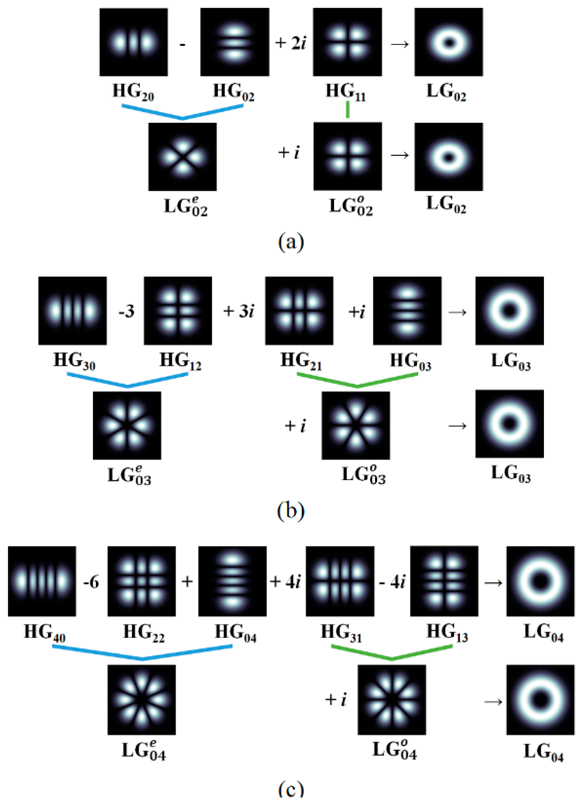
Figure 2.
(a) Waveguide structure for simultaneously guiding l = ±1 OAM mode and l = ±2 OAM modes; and (b) mode effective index dependency on waveguide parameters. Optimal design parameters are W1 = 1.118 μm, L1 = 0.921 μm, W2 = 1.626 μm, and L2 = 1.504 μm.
Figure 2.
(a) Waveguide structure for simultaneously guiding l = ±1 OAM mode and l = ±2 OAM modes; and (b) mode effective index dependency on waveguide parameters. Optimal design parameters are W1 = 1.118 μm, L1 = 0.921 μm, W2 = 1.626 μm, and L2 = 1.504 μm.

Figure 3.
HG-similar mode field distributions in the designed waveguide. The mode effective indices (neff) of (a) HG01; (b) HG10; (c) ; and (d) are 3.215525, 3.215482, 3.05968, and 3.059751, respectively.
Figure 3.
HG-similar mode field distributions in the designed waveguide. The mode effective indices (neff) of (a) HG01; (b) HG10; (c) ; and (d) are 3.215525, 3.215482, 3.05968, and 3.059751, respectively.

Figure 4.
Field (Ex, horizontal component) and phase distributions of the OAM modes with the designed component guided modes: (a) electric field and (b) phase distributions for the l = ±1 OAM mode; and (c) the electric field and (d) phase distributions for l = ±2.
Figure 4.
Field (Ex, horizontal component) and phase distributions of the OAM modes with the designed component guided modes: (a) electric field and (b) phase distributions for the l = ±1 OAM mode; and (c) the electric field and (d) phase distributions for l = ±2.

Figure 5.
HG-similar component mode field distributions in the designed waveguide for l = ±3 OAM mode: (a) and; (b) modes. Field (Ex, horizontal component) and phase distributions of the resulting OAM mode: (c) electric field and (d) phase distributions.
Figure 5.
HG-similar component mode field distributions in the designed waveguide for l = ±3 OAM mode: (a) and; (b) modes. Field (Ex, horizontal component) and phase distributions of the resulting OAM mode: (c) electric field and (d) phase distributions.

Figure 6.
HG-similar component mode field distributions in the designed waveguide for l = ±4 OAM mode: (a) and;(b) modes. Field (Ex, horizontal component) and phase distributions of the resulting OAM mode: (c) electric field and (d) phase distributions.
Figure 6.
HG-similar component mode field distributions in the designed waveguide for l = ±4 OAM mode: (a) and;(b) modes. Field (Ex, horizontal component) and phase distributions of the resulting OAM mode: (c) electric field and (d) phase distributions.

Figure 7.
Fabrication process of the proposed waveguide.

© 2019 by the authors. Licensee MDPI, Basel, Switzerland. This article is an open access article distributed under the terms and conditions of the Creative Commons Attribution (CC BY) license (http://creativecommons.org/licenses/by/4.0/).
Share and Cite
MDPI and ACS Style
Lee, I.J.; Kim, S. On-Chip Guiding of Higher-Order Orbital Angular Momentum Modes. Photonics 2019, 6, 72. https://doi.org/10.3390/photonics6020072
AMA Style
Lee IJ, Kim S. On-Chip Guiding of Higher-Order Orbital Angular Momentum Modes. Photonics. 2019; 6(2):72. https://doi.org/10.3390/photonics6020072
Chicago/Turabian StyleLee, In Joon, and Sangin Kim. 2019. "On-Chip Guiding of Higher-Order Orbital Angular Momentum Modes" Photonics 6, no. 2: 72. https://doi.org/10.3390/photonics6020072
Note that from the first issue of 2016, this journal uses article numbers instead of page numbers. See further details here.