Abstract
Diffraction of light in periodic structures is observed in a variety of systems including atoms, solid state crystals, plasmonic structures, metamaterials, and photonic crystals. In metamaterials, lattice diffraction appears across microwave to optical frequencies due to collective Rayleigh scattering of periodically arranged structures. Light waves diffracted by these periodic structures can be trapped along the metamaterial surface resulting in the excitation of surface lattice resonances, which are mediated by the structural eigenmodes of the metamaterial cavity. This has brought about fascinating opportunities such as lattice-induced transparency, strong nearfield confinement, and resonant field enhancement and line-narrowing of metamaterial structural resonances through lowering of radiative losses. In this review, we describe the mechanisms and implications of metamaterial-engineered surface lattice resonances and lattice-enhanced field confinement in terahertz metamaterials. These universal properties of surface lattice resonances in metamaterials have significant implications for the design of resonant metamaterials, including ultrasensitive sensors, lasers, and slow-light devices across the electromagnetic spectrum.
1. Introduction
Optical anomalies observed by Robert W. Wood in his diffraction grating experiments [1] in 1902 opened up two interesting research areas, categorized into diffractive anomaly and diffusive anomaly.
The diffractive anomaly refers to discontinuities in reflectivity measurements at unique combinations of illumination angle and wavelength, which were first observed by Robert W. Wood as resonant anomalies in grating structures [1]. It was later interpreted by Lord Rayleigh to be a diffraction order and is referred to as Rayleigh anomaly described by a simple one-dimensional grating equation [2,3]:
and is a Rayleigh wavelength, is the grating period, is the refractive index of the diffracting medium and is the angle of incidence. This anomalous scattering allows the observation of extraordinary reflection, transmission, emission of light and nearfield enhancement [4,5,6,7,8,9,10,11,12,13,14].
The diffusive anomaly is closely linked to plasmonics and was explained by Ugo Fano in 1941 to be excitations of surface plasmon polaritons (SPPs) on a periodic metal-dielectric interface [15]. This excitation arises from the coupling of electromagnetic waves to the oscillating electron plasma in conductors, which is evanescently confined at the metal and dielectric interface.
Another resonant phenomenon that has been studied extensively and arises from the electron plasma of conductors is the localized surface plasmon (LSP). It is specific to the scattering of subwavelength-size conductors and dependent on the geometry of the conducting particle. The applications of LSPs include subwavelength imaging, sensing, lensing and lasing [16,17,18,19,20,21,22,23,24,25,26,27].
While LSPs are dependent on geometry, SPP excitation requires momentum matching and the momentum of a SPP supported by a single continuous metal-dielectric interface is given by the SPP wave vector [28,29]:
where is the SPP’s angular frequency and is the speed of light in vacuum, while and are the permittivity of the metal and dielectric, respectively.
Equation (2) can be extended to a perforated interface that is periodic in one (, with ) or two () dimensions. Since the surface waves are confined to planar interfaces, higher dimensions are not considered. Using Bloch wave momentum conservation from the grating coupler equation: , where are the orders of periodicity, is the in-plane momentum of the incident light at the metal-dielectric interface, is the overall momentum of the incident light, while and are the reciprocal lattice vectors for the periods and along the unit vectors and . At normal incidence and the expression for the surface lattice resonance (SLR) frequency can be defined to be [30,31]:
where is the effective permittivity of the metal-dielectric interface and (i,j) are integer indices defining the SLR order along (x, y). For an interface that is periodic in two dimensions (x, y), i.e., a 2D grating, both indices can be non-zero. For a 1D grating we have and the square root simplifies to and for a square lattice it simplifies to . This expression can also be obtained from Equation (1) at normal incidence ().
If the real part of the SPP in-plane eigenfrequency dispersion curves from Equation (2) is below the vacuum light line while the imaginary part is negligible, this indicates a bounded surface wave or guided mode resonance. They manifest as a broad resonance peak or dip, while Rayleigh anomalies are observed as sharp peaks/kinks in the transmission spectrum [32].
Surface waves can exist on periodic corrugated surfaces of any material. They are a result of diffraction of light from surface structures and also, in case of metals, of SPP excitation, where light couples to plasmons of the metal. Surface waves can be used to couple to metamaterial resonances, enabling various optical phenomena that are discussed below.
At terahertz frequencies, metals are very conductive and often taken to be perfect electric conductors (, as their plasma frequencies are in the visible to ultraviolet part of the electromagnetic spectrum. Thus, the effective permittivity can be approximated as at terahertz frequencies [33]. This indicates that due to the high conductivity of metals at THz frequencies, the properties of SLRs only depend on the dielectric that forms an interface with the metal. This expression can also be extended to periodically arranged metallic metasurfaces, as one key feature that metasurfaces have in common with gratings is their periodicity. Therefore, the SLR expression was studied extensively in plasmonics [34] and now could be extended to metasurface physics. SLRs could be used to couple with the eigen or coupled resonances of metamaterial structures to show very interesting effects. These effects include extraordinary transmission, reduction of radiative losses for high quality (Q) factor resonances, electromagnetically induced transparency and strong coupling physics between SLRs and metamaterial resonances [35,36,37,38,39,40,41,42,43]. For a long time, the terahertz region of electromagnetic spectrum was being referred to as technological gap between the infrared and microwave frequencies, which required more efficient and compact terahertz devices, sources and detectors [44]. Now, the terahertz regime could potentially underpin the next generation of information and communication technology [44,45] as the communication carrier frequencies have been increasing continuously. Terahertz waves have also been proven to be beneficial in the medical and biological field as they are non-destructive and able to observe intermolecular vibrations that other frequency regimes cannot access [46,47,48,49,50]. Another sector where terahertz waves have tremendous applications is that of homeland security. Due to the high conductivity of metals, metal detection imaging in airport security can be improved with THz technology and due to the access to intermolecular vibrations, illegal drugs and explosives can be easily identified.
This review will cover the important properties of SLRs, starting with the role of the lattice period which not only determines the frequency of the SLRs but also coherent collective excitations in metamaterials. We will discuss how coupling of SLRs to metamaterial resonances brings about Q-factor-enhancement, lattice-induced transparency, and lattice-mediated strong coupling in metamaterial systems. Finally, we share an outlook on the role of lattice coupling in metamaterial devices which can greatly benefit from the more unique and advantageous properties of SLR effects.
2. Effects of Packing Densities in Metamaterials
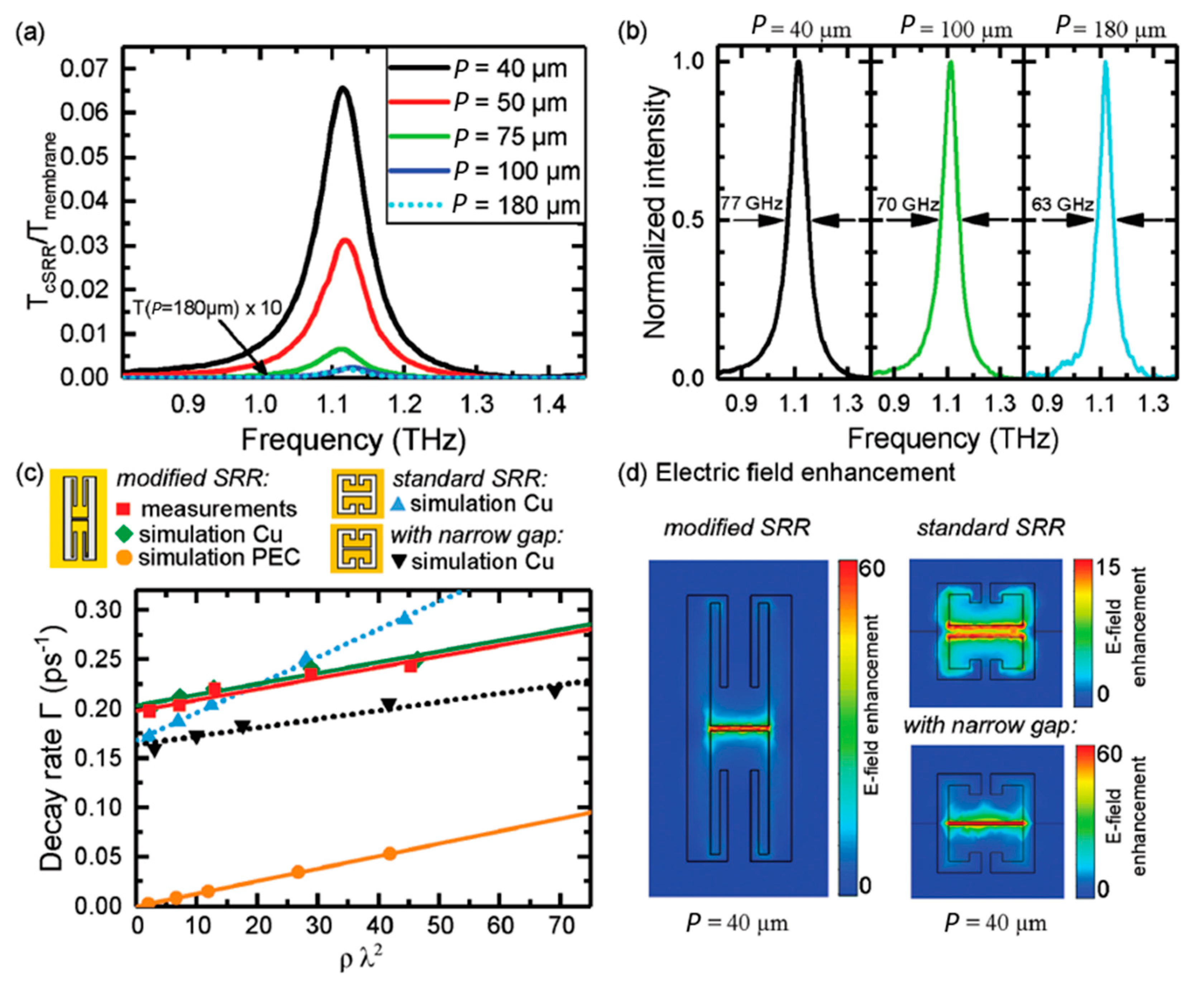
The periodicity of metamaterials controls their SLRs; however, it also determines the packing density of resonators, which has additional effects on metamaterial properties. Periodically arranged subwavelength resonators collectively respond to incident light but only a finite number of resonators is coupled in this collective resonant effect. The arrangement of resonators affects the resonance linewidth and depth as well as nearfield subradiant coupling [51,52,53,54,55,56]. Though the lattice period is used in investigating the metamaterial collective responses, the SLR is not required. To avoid SLR effects, J. Keller et al. used a silicon membrane instead of a thick silicon substrate to detune the SLR away from their metamaterial’s resonance at 1.12 THz [55]. The metamaterial structure is a complementary split ring resonator (SRR) or “Babinet structure”, consisting of an array of resonating apertures in a continuous copper film. Varying the lattice period between and 180 , they observed a resonance linewidth narrowing as the lattice period increased as shown in Figure 1. Here, the resonance narrowing is not through resonant coupling to a SLR (which will be reviewed in the next section) but is due to the decrease of the meta-atom density as the resonator arrays become sparser. This linewidth () narrowing of a resonance at frequency can be quantified in terms of the Q-factor, , or the related decay rate given by, . A linear dependence of the decay rate on the resonator density and the square of the wavelength, , was observed (Figure 1c). This linear effect was interpreted as “Dicke superradiance” that arises from the coherent collective coupling of electric dipoles in the metamaterial system. A Lorentzian line shape is observed for the homogenously broadening resonance when the resonators are densely packed. In contrast, Gaussian line shapes would be expected due to spectral broadening in inhomogeneous systems. A signature of superradiance in the linewidth broadening in metamaterials was also reported by R. Singh et al., where asymmetric line shapes of resonances were observed for larger lattice constants due to weak SLR coupling [56]. Another study, by V. A. Fedotov et al., investigates the collective response of metamaterials as a function of the number of resonators and observes Q-factor-saturation at hundreds of metamolecules in a coherent metamaterial. This indicates the number of resonators that can be coupled to determine the overall response of a coherent collective system and plays a role in engineering resonance characteristics, e.g., for lasing spasers [51].
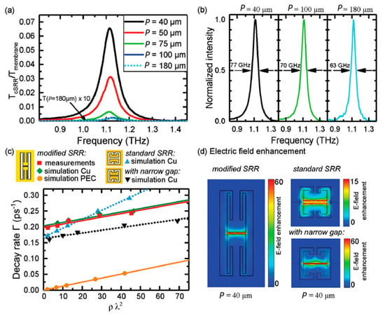
Figure 1.
Split ring resonator (SRR) arrays with different packing densities. (a) Transmission amplitude of complementary SRR arrays for lattice periods varying from, to 180 . Transmission for is multiplied by 10 to be visible on the same scale. (b) Normalized intensity transmission spectra for and 180 with their respective full width at half maximum. (c) The decay rate as a function of the resonator density multiplied by the square of the wavelength for the measured sample and simulations for three SRR geometries [see panel (d)]. Measurements are for a Si-membrane with Cu resonators and simulations assume a conductivity of for copper or a perfect electric conductor (PEC) as indicated. (d) Simulated electric field enhancements for for the three SRR geometries. Adapted with permission from ref [55], John Wiley and Sons.
3. High-Q Resonances
Metamaterial resonances are generally constrained by losses, which can be classified as radiative and non-radiative. Non-radiative losses are mainly due to the lossy nature of materials. Therefore, material selection plays an important role in reducing non-radiative losses and use of semiconductors, optimized resonator geometries and gain media has been proposed to reduce or compensate such losses [57,58,59]. Among metals, those with high conductivity, e.g., silver and gold, have low scattering rates of free electrons leading to low non-radiative losses, also known as resistive or ohmic losses [58]. However, the oscillation of the free electrons couples easily to free space causing metal structures to have large radiative losses. When radiative losses dominate, their reduction will enable the metamaterial to trap energy for a longer duration, resulting in an improved quality factor of metamaterial resonances. Radiative losses can be reduced via smart array designs and, in this review, we will discuss how this can be achieved by resonant coupling of localized metamaterial responses with SLRs that are inherent to the periodic nature of metamaterials. Such coupling can be achieved by adjusting the SLR-wavelength (frequency) by varying the period P of the metamaterial array according to Equation (3), such that the SLR’s spectral position becomes similar or identical to that of the metamaterial resonator’s structural resonance, [38]. As shown by A. Bitzer et al. for the simplest case of normal incidence illumination of an array of point scatterers in vacuum, when , scattered field is trapped in the plane of the metamaterial array (lobes parallel to the y-axis of Figure 2). The trapped fields radiate along the plane of the array and can couple with localized metamaterial resonances, enhancing the localized fields within the metamaterial. This causes a reduction of radiative losses and can be observed as narrowed linewidth of the metamaterial resonances in the far-field. For example, this increases the resonance Q-factors of a simple split ring wire resonator supporting an inductive-capacitive (LC) mode and a quadrupole mode. Lattice mode coupling is very versatile and has been demonstrated on different types of metamaterial [35,36,37,38,39,41,42] and plasmonic resonances [16,17,18,34,43,60,61,62,63,64,65,66,67,68,69,70,71,72]. This review highlights the SLR coupling to LC, dipole and hybridized modes of metamaterial resonators.

Figure 2.
Scattering along periodic interfaces. Far-field intensity distribution of scattered light calculated for 1D arrays with different periodicities Py located in the xy-plane and illuminated along z. Adapted with permission from ref [38], The Optical Society.
3.1. Fundamental Resonances (Dipole and LC)
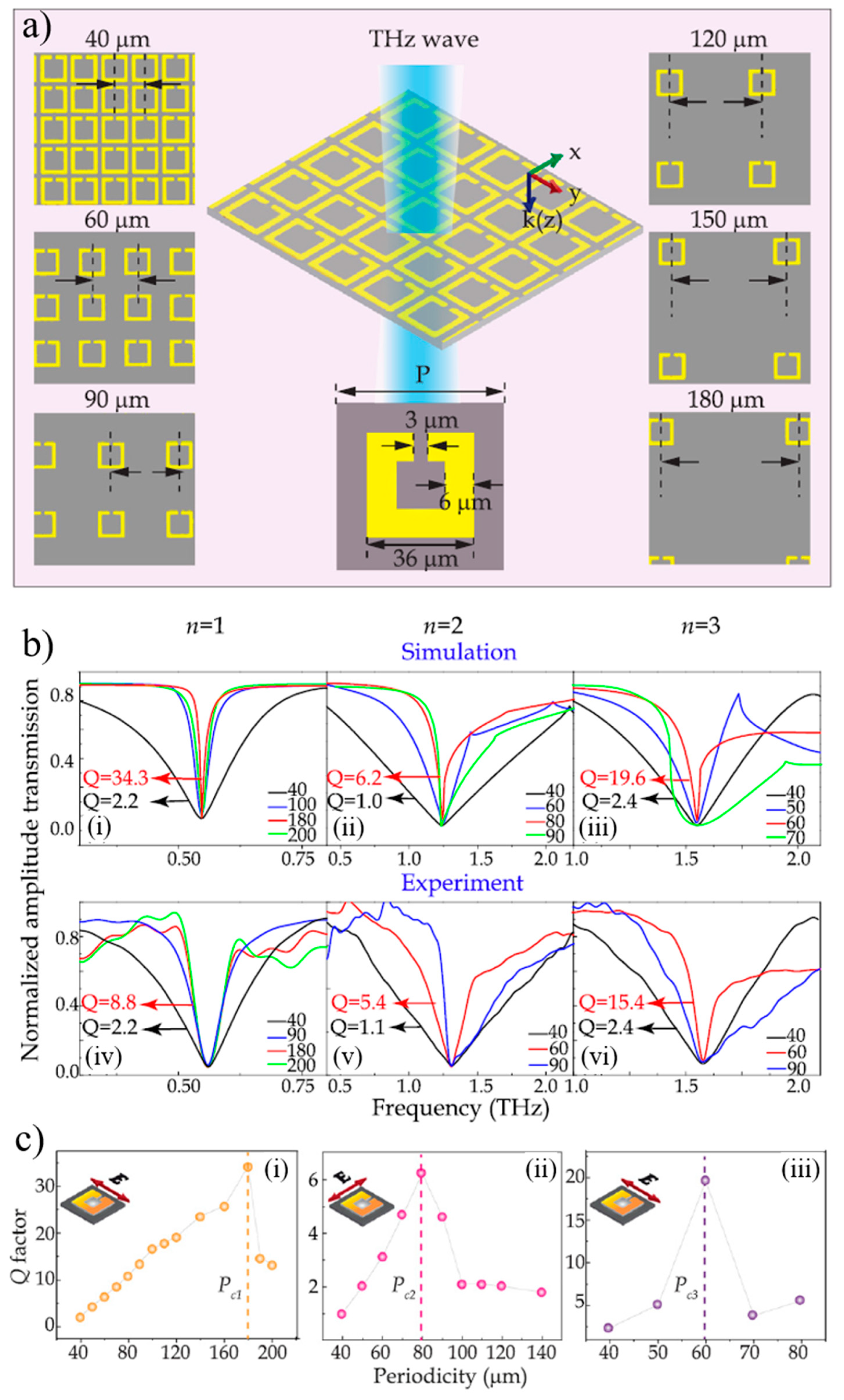
A simple metallic bar resonator oriented parallel to the incident polarization is able to support a dipole resonance mode characterized by charge oscillations, LSPs, along the bar. A simple split ring guides these charge oscillations along an inductive loop with a capacitive gap as shown in Figure 3a. N. Xu et al. demonstrated Q-factor-enhancement of normal modes of a SRR through coupling to a lattice mode by varying the lattice period [37]. Resonator arrays with different periods excited by THz waves of appropriate polarization were used to couple a lattice mode to the metamaterial’s LC mode (), dipole mode () and quadrupole mode (). The LC and quadrupole modes are excited by incident light that is polarized perpendicular to the resonator’s symmetry axis while the dipole mode is excited by light polarized parallel to the symmetry axis. Figure 3b shows the resonance line-narrowing and broadening of each mode as the lattice period increases from to , where the narrowest linewidth occurs when the lattice mode matches the resonance frequency of the respective metamaterial mode. At these critical periods (), the Q-factor is maximized due to the reduction of loss in the system, as shown in Figure 3c. This coupling enhances the Q-factor of the fundamental modes (LC and dipole mode) up to fifteen-fold and six-fold, respectively.
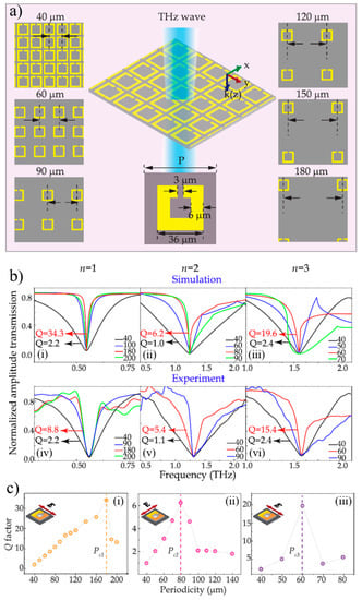
Figure 3.
Enhancing split ring resonances using lattice modes. (a) Optical microscope images of the LC resonator metamaterial with its fixed resonator dimensions and varying period from 40 to 180 shown in the insets. (b) Simulated (i–iii) and measured (iv–vi) normalized transmission amplitude spectra showing different resonance modes () for different periods. The resonant transmission minima were aligned to highlight the narrowing of the resonance linewidth. (c) Q-factor-enhancement in lattice-matched split ring resonator arrays. Q-factor of the (i) LC (), (ii) dipole () and (iii) quadrupole () modes as a function of lattice period. The polarization of the incident field is shown in the insets and the critical periods , where the lattice mode couples to the metamaterial resonance, are indicated by dashed lines. Adapted with permission from ref [37], AIP Publishing.
3.2. Hybridized Resonances
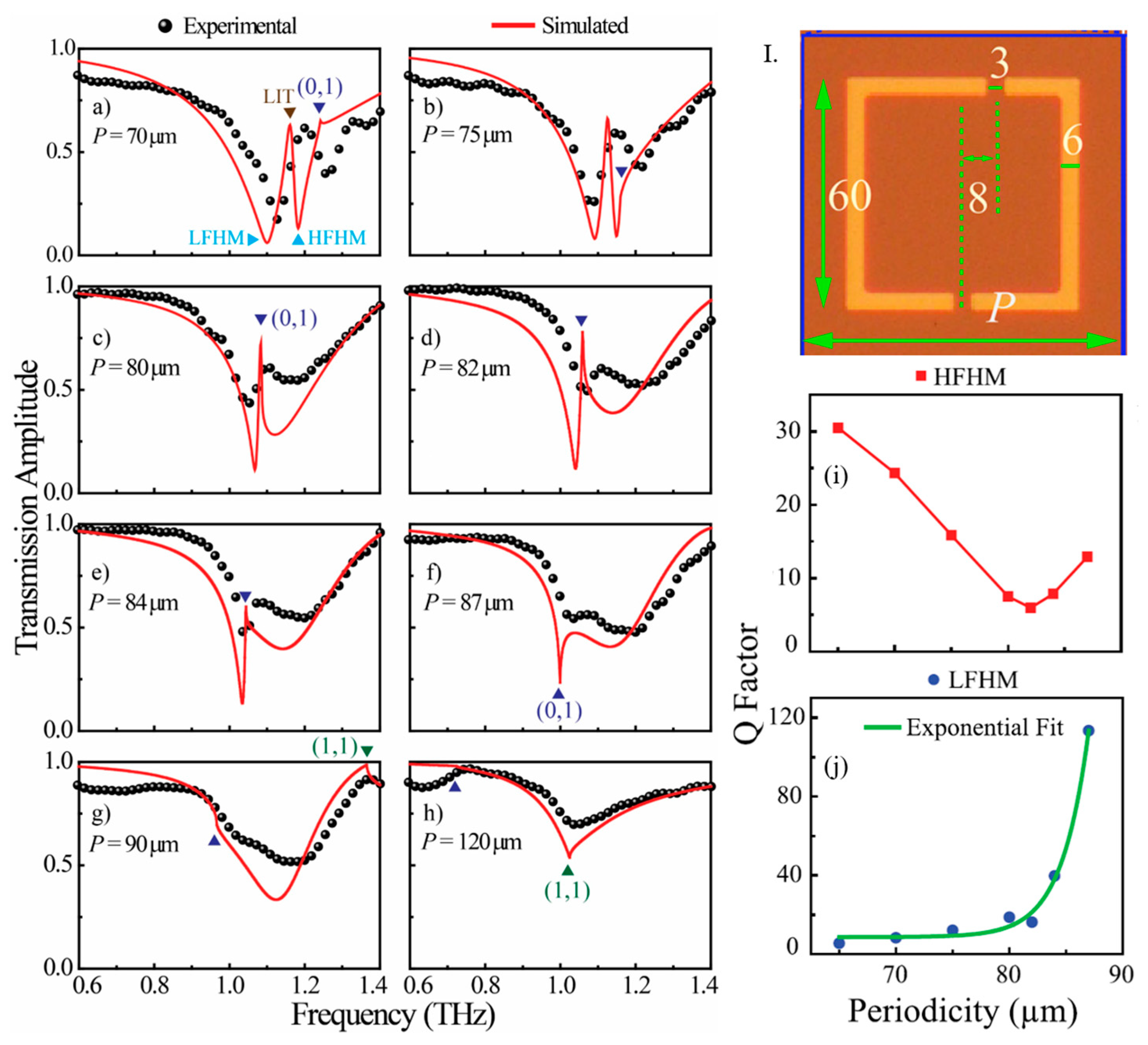
In metamaterials, split modes or hybridized modes arise from nearfield coupling of neighboring elements (called meta-atoms) in the same unit cell. Typical hybridized modes are characterized by symmetric and anti-symmetric charge oscillations in the meta-atoms. While symmetric and anti-symmetric resonant modes can, in principle, exist in entirely symmetric systems, excitation of anti-symmetric hybridized modes requires some form of symmetry breaking. Such symmetry breaking arises from pairing meta-atoms of slightly different size or geometry [73] as well as meta-atom arrangements or illumination conditions (e.g., direction or polarization) that result in different excitation of the coupled meta-atoms [74,75,76]. For example, a difference in geometry detunes the resonance frequencies of the meta-atoms to be non-degenerate, thereby splitting the resonances into symmetric and anti-symmetric modes, which are separated by an amount quantified by their coupling strengths. This is an analogue of electromagnetically induced transparency (EIT) in atomic systems [77,78,79,80]. For example, T. CW. Tan et al. used a ring resonator with a second split (compared to the LC resonator of Figure 3) that was shifted away from the central axis of the resonator to introduce an asymmetry [36]. The resulting unit cell has resonator arms of different length, lifting the degeneracy of resonance frequencies that would be present in a symmetric structure. Using different lattice periods, the SLR frequency was then adjusted to match each of the hybrid mode frequencies and resonance line-narrowing and Q-factor enhancement was observed, see Figure 4. A maximum Q-factor of 113 was obtained when the lattice matched the lower frequency hybridized mode (LFHM), which is one order magnitude higher than without lattice matching.
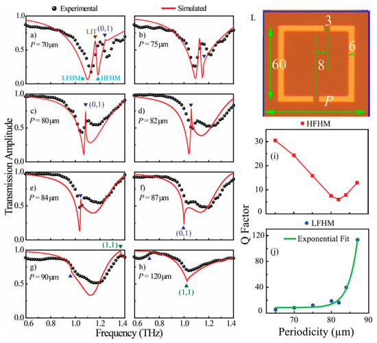
Figure 4.
Coupling of hybridized resonator modes to a lattice mode. (I) The unit cell with dimensions in . (a–h) Experimental (black spheres) and simulated (red solid lines) transmission amplitude of a terahertz asymmetric split ring resonator array with the lattice period varying from P = 70 to 120 . The split modes, low frequency hybrid mode (LFHM) and high frequency hybrid mode (HFHM), are indicated alongside the lattice-induced transparency (LIT) in (a). The fundamental lattice mode (0,1) and the (1,1) order lattice mode are indicated by the dark blue and green triangles, respectively. (i,j) Q-factor of the HFHM and LFHM of the asymmetric metamaterial for varying periodicities. Adapted with permission from ref [36], AIP Publishing.
4. Lattice-Induced Transparency (LIT)
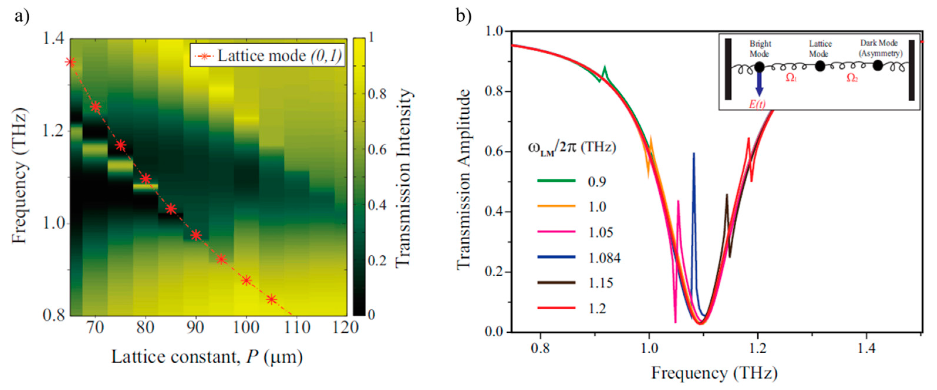
EIT is a phenomenon whereby an absorbing medium becomes transparent to a resonant probe beam under the influence of the stronger control or pump beam, resulting in a narrow transparency window. Within the transparency window, light experiences an anomalous phase change because of a steep dispersion. The induced steep dispersion of the medium can slow the propagation of light pulses by several orders of magnitude [41,81,82,83] and enhances nonlinear interactions [84]. Such narrow and highly dispersive transparency windows possess a high Q-factor and are a promising platform for sensing and nonlinear applications. M. Manjappa et al. demonstrated a different phenomenon that introduces a sharp transmission peak by coupling the broad dipolar resonance of an asymmetric square resonator to the first order lattice mode as shown by Figure 5a [35]. Previous understanding of metamaterial EIT is based on the nearfield coupling of asymmetric metamaterial resonators: One so-called “bright” mode resonator will be coupled directly to the incident field and will have a broader resonance line width. A nearby so-called “dark” mode resonator is excited through nearfield coupling from the “bright” mode resonator [85,86]. The bright mode is usually represented in the spectra as a bright dipolar resonance and the dark mode as an interference in the dipolar continuum resulting in a Fano resonance or EIT. This bright-dark mode coupling can be theoretically modeled as two coupled classical oscillators [87]. Manjappa et al. observed that the lattice mode, in addition to the asymmetric dark mode, is also involved in inducing a narrow transparency peak termed lattice-induced transparency (LIT). The lattice mode can be modeled as another dark mode oscillator, as the energy diffracted from the incident field is being trapped within the near field of the metamaterial array and is not coupled to free space. Hence, the LIT system can be theoretically modeled using three coupled oscillators as seen in the insert of Figure 5b and the corresponding equations of motion are:
where and are the amplitudes, angular resonance, and the damping frequencies of the bright, lattice, and dark modes, respectively. and are the bright-lattice and dark-lattice mode coupling strengths, respectively. In this model, the lattice mode is mediating the coupling between the bright mode and the asymmetric dark mode as expressed in Equation (4b). The lattice mode is an additional dark mode that induces strong nearfield coupling between the bright dipole and the asymmetric dark mode, thereby enhancing the sharpness (Q-factor) of the induced transparency peak. Under resonant conditions, and , the scattering amplitude of the bright eigenmode can be obtained from Equations (4a)–(4c). The transmission amplitudes in Figure 5b were obtained for realistic parameters of , , ), , and different lattice mode frequencies, . As the SLR frequency is varied across the dipolar spectrum, the transparency peak is weakest at either side of the dipole spectrum and strongest when . The model does not include inter-unit cell coupling. These results demonstrate a unique phenomenon of inducing a narrow transparency peak, with Q-factors ranging from 25 to 91 extracted from Figure 5a. This method also facilitates the frequency agility of the sharp transparency peak, which can be positioned precisely over a broad frequency range by choosing the lattice period. M. C. Schaafsma et al. [41] reported lattice-enhanced transparency and slow-light effects in a periodic array of detuned dipole resonators. They considered metallic rods of two different sizes, in which the coupling of these metal rods with the lattice modes results in enhancement of the transmission window. Narrow transmission resonances mediated by the lattice may have applications in the slow-light devices [88,89,90] and as optical routers or light modulators for communication networks.
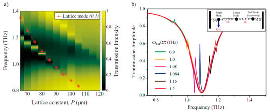
Figure 5.
Lattice-induced transparency. (a) Transmission around a LIT resonance as a function of frequency and lattice constant for split rings as in Figure 4I. The red dashed-dot curve indicates the first order lattice mode (0,1). (b) Transmission amplitude of the associated resonances extracted from the three-oscillator model of Equation (4) for varying lattice mode frequencies. For lattice modes in a silicon substrate, and correspond to lattice periods of P = 95, 80 and 65 , respectively. The schematic shows the underlying classical bright-dark-dark coupled oscillator model. Adapted with permission from ref [35], American Physical Society.
5. Lattice-Mediated Strong Coupling in Metamaterials
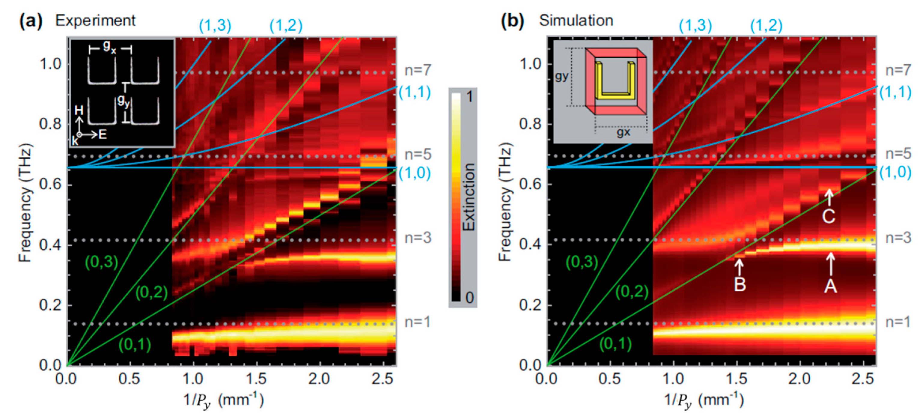
Due to the versatility and simplicity of the lattice mode, it can be coupled to many kinds of periodic systems as discussed above. In case of LIT, a new mode or a split mode emerges when the SLR couples to the metamaterial and the coupling strength can be varied to observe different characteristic behaviors. If the splitting matches an avoidance crossing or anti-crossing eigensolution of a coupled oscillator mode and the coupling strength of the system is greater than the damping rate (), the system is said to be strongly coupled. This can be achieved through coupling of a lattice mode to different metamaterial systems, directly, or indirectly, e.g., in case of LIT. Direct coupling of a lattice mode to a single mode resonance resulting in a splitting and anti-crossing was observed by A. Bitzer et al., see Figure 6. The anti-crossing is between the (0,1) lattice mode and the split ring’s plasmonic structural resonance. The splitting occurs at point B in Figure 6b, which marks the strong radiative coupling as shown in [38].
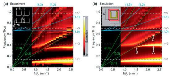
Figure 6.
Strong coupling between a single resonance and a lattice mode. Dispersion diagrams obtained from (a) measured and (b) simulated transmission spectra. The lattice constant, varies from 380 to 1200 while is kept constant at 380 . Plasmonic structural resonances are indicated by the gray dotted lines and the lattice modes by green and blue solid lines. A and B mark weak and strong radiative coupling for the structural mode and a pure lattice mode is marked by C. Adapted with permission from ref [38], The Optical Society.
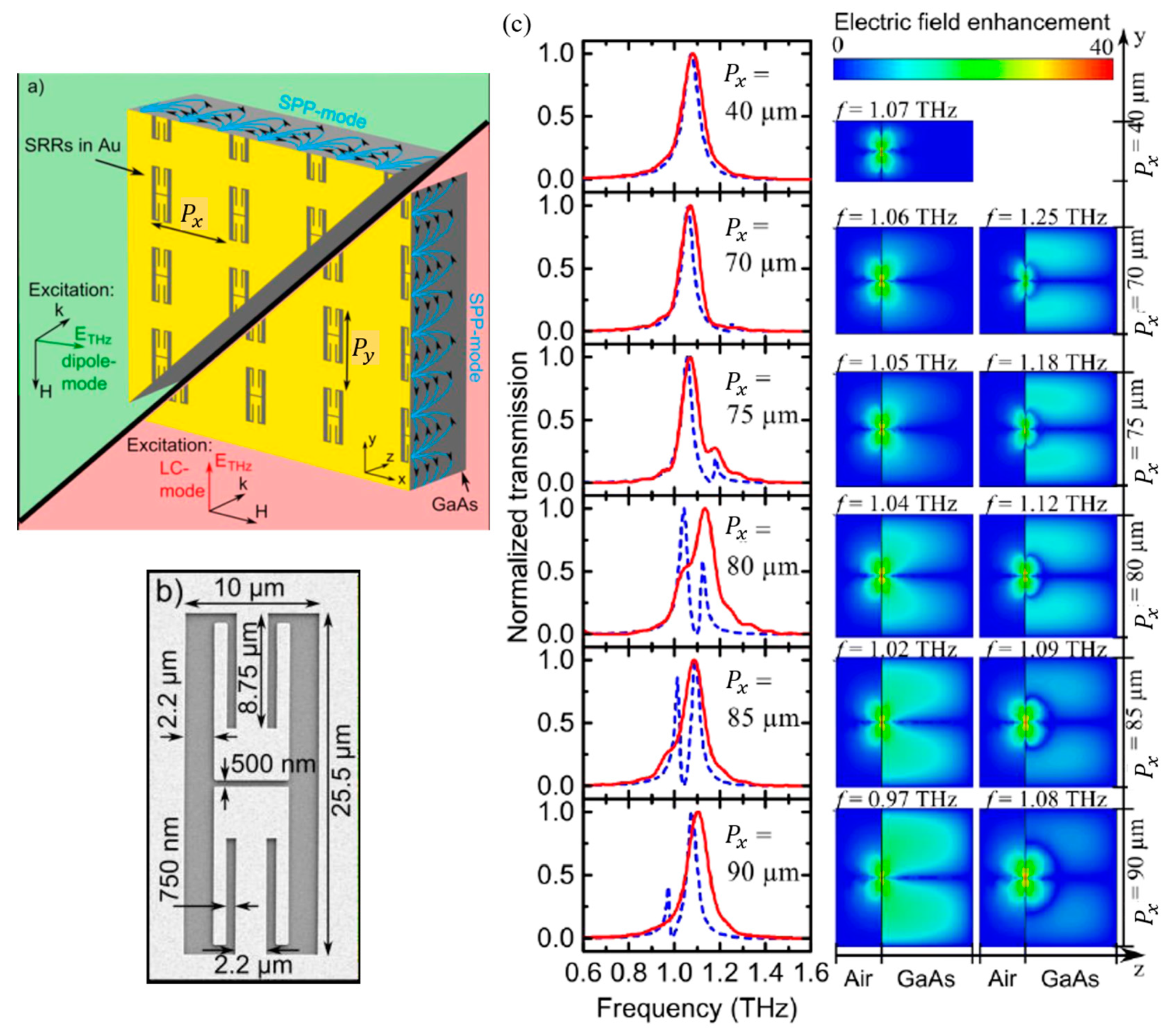
J. Keller et al. employ a complementary LC metamaterial resonator that supports a single, narrow resonance [39]. Similarly, they observed a splitting in the LC resonance when it is coupled to the lattice mode. As their system is also strongly coupled, they were able to observe energy exchange between the modes in terms of resonance transmission amplitude at different lattice spacings, see Figure 7. An anti-crossing between the split LC mode and the SLR was also observed and modeled with a two-coupled oscillator model.
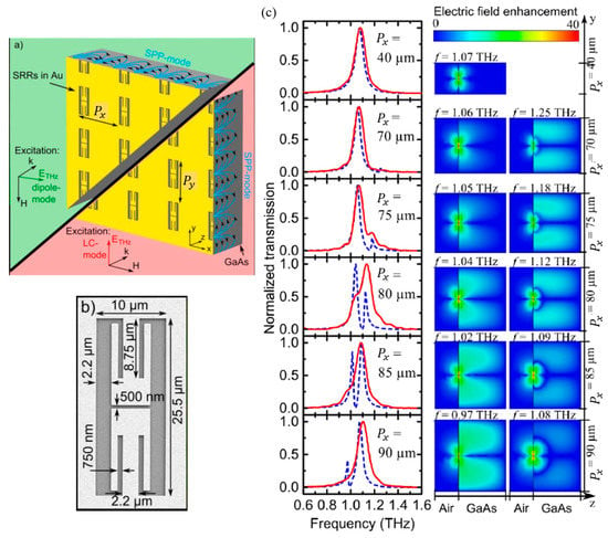
Figure 7.
Lattice-induced resonance splitting. (a) Sample illumination for dipole mode (x-direction) and LC mode (y-direction) excitation. (b) Scanning electron micrograph of one split ring resonator with indicated dimensions. (c) (Left) Normalized transmission spectra of the measured (red solid lines) and simulated (blue dashed lines) metamaterial arrays at different lattice periods . (Right) Simulated electric field distributions plotted in the y-z plane cut in the gap of the resonator. The field maps show the respective split modes for the lattice constants indicated on the right. Adapted with permission from ref [39], AIP Publishing.
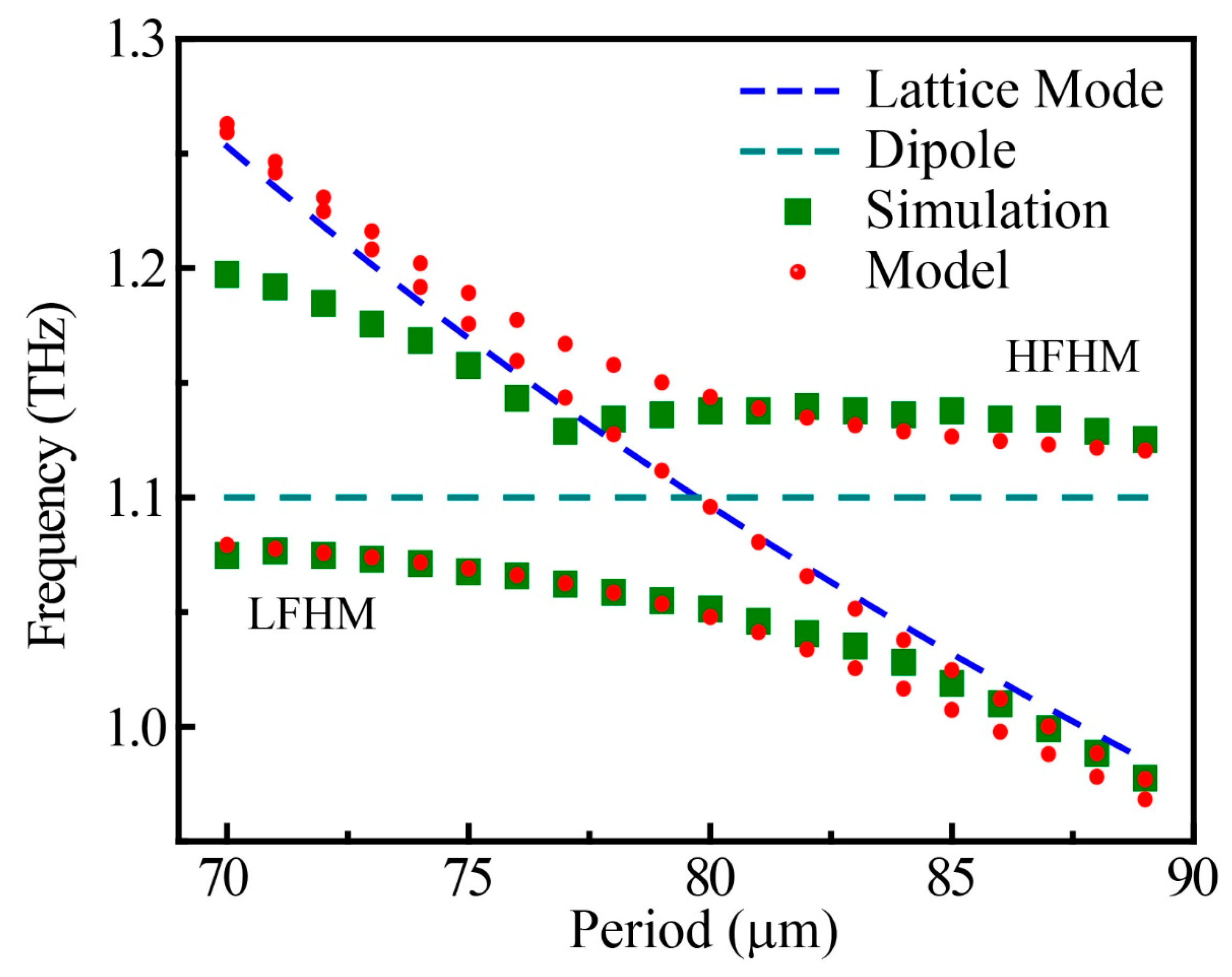
The lattice mode involvement in the hybridization of modes and lattice-induced transparency in arrays of coupled pairs of distinguishable resonators could be described by a three coupled oscillator model, see Equation (4) [35,36]. T. CW. Tan et al. [36] extracted the eigensolution from the model to fit the resonances of the coupled hybridized and lattice modes for asymmetric split ring resonator arrays with different periods. The model shows an anti-crossing that is also seen in simulations, see Figure 8. Some deviation between model and simulated resonance frequencies for the smallest lattice periods may be due to inter-unit cell coupling that is not considered in the analytical model.
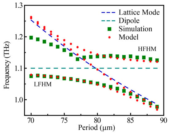
Figure 8.
Analytical model of a lattice-induced anti-crossing. Resonance frequency of the split modes (LFHM and HFHM) of Figure 4 alongside the lattice mode frequency (blue dashed line) as a function of the lattice period according to the simulations of Figure 4 (green squares) and the fitted analytical eigensolution of the three-oscillator model (red circles). An anti-crossing is seen at the intersection of the dipole mode of 1.1 THz (cyan dashed line) and the calculated lattice mode. Adapted with permission from ref [36], AIP Publishing.
6. Future Outlook
6.1. Engineering Resonance Linewidths
Taking advantage of the periodicity of metamaterials, scientists have found that the highly confined surface lattice modes are useful for controlling metamaterial resonances. As reviewed in the previous sections, several resonance characteristics such as narrow spectral width of absorption resonances, narrow transparency windows, and electric field confinement as well as enhancement can be controlled, which is beneficial for micro/nano lasers, sensors, filters and slow-light applications [25,26,27,91,92,93,94,95]. Lattice-enhanced narrow resonances could also be used to couple to primary excitations such as excitons or phonons, as they have comparable linewidths [96,97,98,99].
6.2. Low-Threshold Micro/Nano Lasers
In conventional lasers, the basic components are a pump source, an active gain medium and a resonating cavity. The resonating cavity could be replaced with a metamaterial array, which would change the Fabry-Perot cavity effect into a collective response of the metamaterial array. Assuming a gain medium with suitable transitions, the operating wavelength of conventional lasers is determined by a resonance of the Fabry-Perot cavity, while the operating wavelength of a metamaterial-based laser could be controlled by the meta-atom geometry and periodicity. A thin, layered structure and flexible control over the emission wavelength by scaling the metamaterial geometry would make metamaterial-based lasers versatile and desirable for on-chip device integration, as proposed by N. I. Zheludev et al. [93] The metamaterial array for lasing should support a high-Q mode for light emission with high spatial and temporal coherence. The importance of the high-Q mode is linked to Fermi’s golden rule, where the rate of spontaneous emission is proportional to the local density of optical states which can be enhanced in an optical microcavity by the Purcell factor
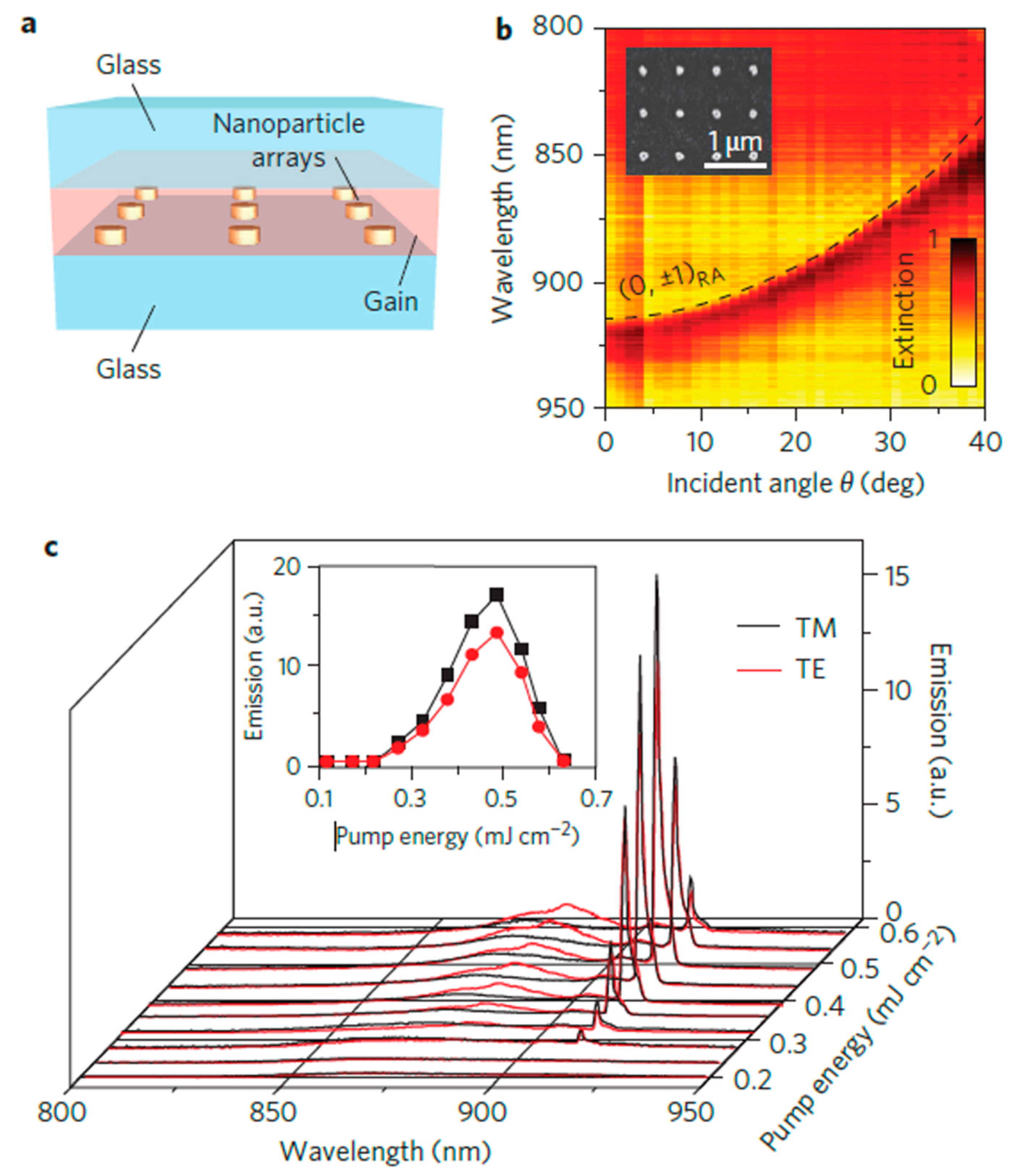
where Q is the cavity quality factor, is the mode volume, is the resonant wavelength and n is the refractive index of the medium. Increasing the local density of optical states not only improves the rate of spontaneous emission but also stimulated emission which is required for lasing. Due to the ultrasmall mode volume of metamaterial resonators, the local density of optical states can be increased up to 1000 times. Together with a thin layer of gain medium, it is possible to achieve emission amplification by orders of magnitude [100]. Use of a SLR with an array of metamaterial resonators could potentially improve the lasing mechanism, as recent results on plasmonic nanoparticle arrays indicate. As shown by Figure 9, a plasmonic dispersion is obtained from the scattering of lattice plasmons of a nanoparticle array on a glass substrate [95]. When covered with a gain medium and illuminated by pump pulses of suitable energy, the structure exhibits a narrow emission line that corresponds to the lattice plasmons. Amplification of lattice plasmon emission was seen for pump energies and saturated at . A four level semi-quantum framework was used to simulate the interaction between the electromagnetic fields and the active gain medium. Below threshold, spontaneous emission dominated, but above threshold stimulated emission was several orders of magnitude higher than spontaneous emission. The nanolocalization of electromagnetic fields in lattice plasmons stimulated excited state molecules in the active medium to transfer energy into plasmons, thus enabling the lasing action. Similarly, lasing has also been demonstrated at the SPP resonance of a metasurface consisting of a hole array in a metal film that is supported by a semiconductor gain layer [101].
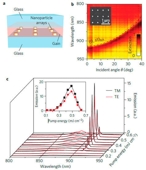
Figure 9.
Lasing in nanoparticle arrays. (a) Schematic of a nanoparticle array laser. (b) Measured extinction spectra as a function of incident angle for a two-dimensional Au nanoparticle array (inset) under transverse-magnetic (TM) illumination. (c) Spectra of light emitted normal to the nanoparticle array for different pump energies. Pulsed laser light of 800 nm wavelength was used to pump the sample array with an IR-140 dye gain medium at an incident angle of . Adapted with permission from ref [95], Springer Nature.
6.3. Sensing
The high Q-factor obtained in SLR-coupled metamaterial resonances reveals the low radiative losses of such metamaterial systems. These low losses make SLR-coupled resonances sensitive to external perturbations and therefore suitable for sensing. The ability to detect a change in refractive index, , through a change in resonance wavelength, is given by a figure of merit () for sensing, , where is the spectral shift per refractive index unit and is the full width at half maximum of the resonance [27]. Since SLR-coupling of metamaterial resonances reduces , it can be used to increase the significantly, thus improving the sensor’s performance. Sensing capabilities of SLRs coupled to LSP resonances of nanoparticles [67] as well as sensing capabilities of high-Q metamaterial resonances have already been reported [19,20,21,27]. Further improvements may be expected from sensing with a SLR coupled to a metamaterial resonance due to Q-factor enhancement and enhancement of confined fields in the resonator that are easily perturbed by a change in environment such as the introduction of an analyte.
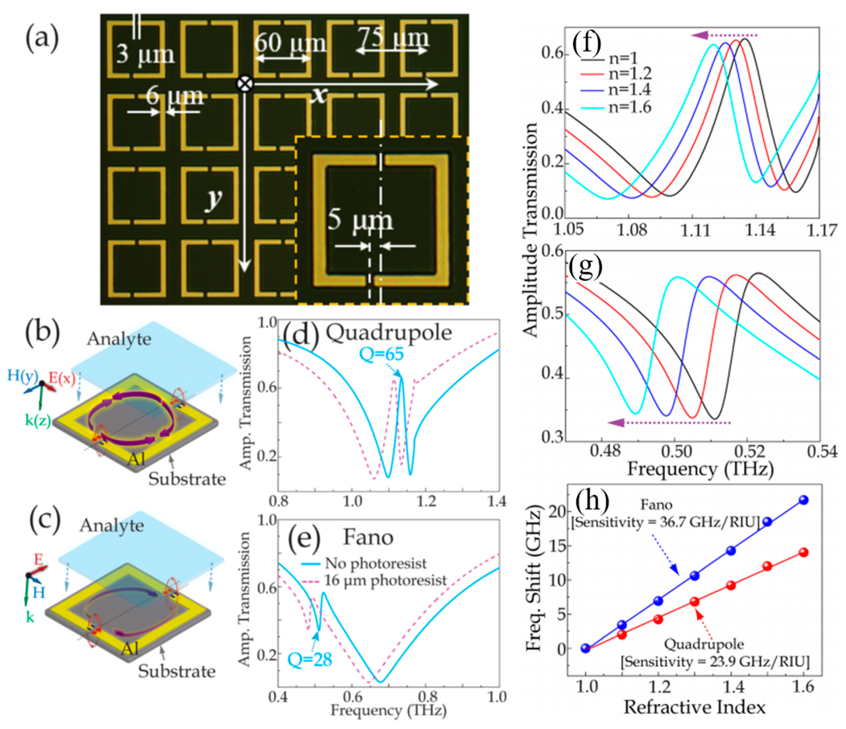
R. Singh et al. demonstrated planar metamaterial sensing using a Fano resonance and the lattice-induced transparent quadrupole mode, as shown in Figure 10 [102]. The authors have shown a frequency shift of the resonance modes with the refractive index of an analyte coating on the metasurface. The electric field of the resonant metamaterial is strongest in the gaps of the SRR. Once the analyte is coated over the resonators and fills the gap, the analyte behaves as a dielectric layer which increases the capacitance of the gaps and enhances the electric field. In their findings, the Fano resonance shows the strongest electric excitation and the field confinement in the gap is further enhanced by the introduction of the analyte. This is responsible for the Fano resonance’s higher sensitivity to its external surroundings and its larger redshift with increasing refractive index in comparison to the quadrupole mode. However, the sensitivity of the structure for refractive index sensing could be enhanced further by coupling the Fano resonance to the SLR, which also depends strongly on changes of the refractive index of the surrounding medium.
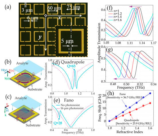
Figure 10.
Refractive index sensing. (a) Optical microscope image of the terahertz asymmetric resonator array with dimensions. Illustration of the illumination conditions for excitation of the metasurface’s (b) quadrupole and (c) Fano resonances alongside transmission spectra of the (d) quadrupole and (e) Fano resonances with and without an analyte layer. Simulated amplitude transmission spectra of (f) quadrupole resonance and (g) Fano resonance when a 4--thick analyte coating with different refractive indices is placed on an asymmetric split ring metasurface. (h) Shift of the quadrupole and Fano resonances as a function of refractive index. Adapted with permission from ref [102], AIP Publishing.
6.4. Slow Light
The strong coupling and LIT effect of the SLR is accompanied by steep dispersion, which increases the group index and reduces the group velocity, slowing down light in the medium. In terahertz spectroscopy, the transmission amplitude is expressed as
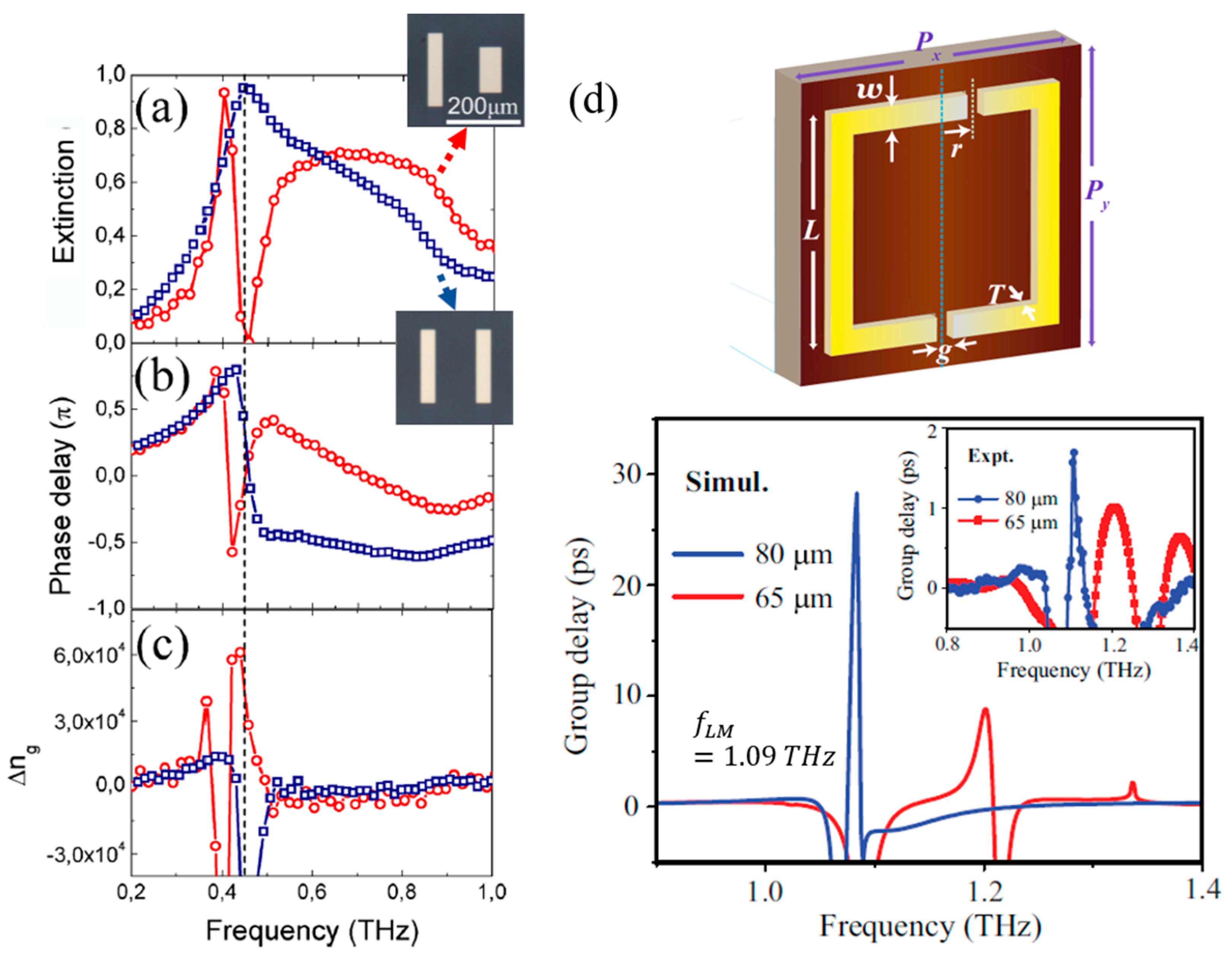
where is the phase delay, is the transmitted field through the sample and is the transmitted field through the bare substrate. The THz extinction spectrum of the sample is given as . Figure 11 shows the extinction spectra, phase delay, and group index of metamaterials from M. C. Schaafsma et al. [41]. The spectra correspond to metamaterials based on either symmetric pairs of dipole resonators (equal length, blue) or asymmetric pairs of dipole resonators (different length, red). The symmetric structure has a broad extinction maximum at 0.45 THz, see Figure 11a. Asymmetry causes a transparency window to open within the broad resonance. The corresponding frequency-dependent phase delays obtained from the Fourier transforms of the THz pulses are shown in Figure 11b. The blue curve representing the symmetric resonators has the characteristics of a damped harmonic oscillator: the phase changes sign at the extinction maximum. In contrast, the red curve representing the asymmetric resonators changes sign twice near the transmission window, resulting in large positive and negative group indices , which can be calculated from the phase delay
where is the speed of light in vacuum, is the group velocity, phases are in units of radians and L is the thickness of the resonator array. Figure 11c shows the group index of the symmetric (blue) and asymmetric (red) nanowire metamaterials. The maximum group index for the latter exceeds with a group velocity of only at 0.45 THz. At this frequency, the wave is delayed by scattering within the array before it is reradiated in the forward direction. Strong enhancement in the group delay and group index was also reported by M. Manjappa et al. [35] for an array of asymmetric SRRs (with dimensions similar to Figure 4I), where they report a record group delay of 28 ps (Figure 11d) for THz pulses and a group index of 4.5 , at a LIT peak for P = 80 μm [35].
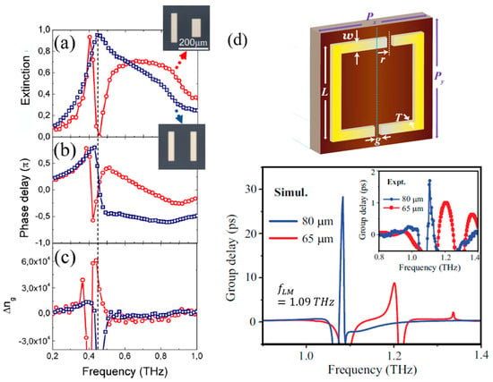
Figure 11.
Slow light. (a) Extinction, (b) phase delay and (c) group index spectra of arrays of pairs of identical “symmetric” (blue) and distinguishable “asymmetric” (red) gold nanorods. The vertical dotted line at 0.45 THz indicates the frequency of the induced transparency in the asymmetric array. Adapted with permission from ref [41], American Chemical Society. (d) Numerically obtained (main graph) and experimental (inset) group delays for asymmetric split ring metamaterials with lattice constants and . Adapted with permission from ref [35], American Physical Society.
7. Conclusions
In conclusion, the topic of surface lattice resonances has evolved from an anomaly seen in diffraction gratings into an extensive field of research that has generated numerous advances in plasmonics and now in metamaterials. SLRs are inherent to any periodic structure and can therefore be exploited to enhance collective resonances of any periodic metamaterial. Placing engineered metamaterial resonators in a lattice and matching the resonant response of the individual resonator to a SLR offers reduced radiative losses, resonances with narrower linewidth and thus increased Q-factor and local field enhancement, as well as phenomena such as lattice-induced transparency, strong coupling, extremely slow light propagation, and giant Purcell enhancement of light emission. Arguably, lattice modes may be exploited to enhance the performance of any periodic array of resonators and therefore they provide an optimization strategy for any resonant metamaterial application, and for coupling of periodic structures to other excitations, such as excitons and phonons. In particular, SLRs provide opportunities for resonant metamaterial applications such as metamaterial-based sensors, lasers, and slow-light devices. While the focus of this review is on electromagnetic metamaterials, we note that the concepts are more widely applicable as lattice modes are a general consequence of waves in periodic media.
Author Contributions
T.C.T. drafted the article by collecting the data from the references and inputs from all authors. E.P. and R.S. supervised and revised the article.
Funding
The authors acknowledge the funding support from Singapore Ministry of Education (MOE) (Grant No. MOE2016-T3-1-006 and MOE2017-T2-1-110) and the UK’s Engineering and Physical Sciences Research Council (Grant EP/M009122/1). No new data were created as part of this review.
Conflicts of Interest
The authors declare no conflict of interest.
References
- Wood, R.W., XLII. On a remarkable case of uneven distribution of light in a diffraction grating spectrum. Philos. Mag. 1902, 4, 396–402. [Google Scholar] [CrossRef]
- Rayleigh, L. On the dynamical theory of gratings. Proc. R. Soc. Lond. Ser. A 1907, 79, 399–416. [Google Scholar] [CrossRef]
- Rayleigh, L., III. Note on the remarkable case of diffraction spectra described by Prof. Wood. Lond. Edinb. Dublin Philos. Mag. J. Sci. 1907, 14, 60–65. [Google Scholar] [CrossRef]
- Christ, A.; Zentgraf, T.; Kuhl, J.; Tikhodeev, S.G.; Gippius, N.A.; Giessen, H. Optical properties of planar metallic photonic crystal structures: Experiment and theory. Phys. Rev. B 2004, 70, 125113. [Google Scholar] [CrossRef]
- Gadsdon, M.R.; Hooper, I.R.; Sambles, J.R. Optical resonances on sub-wavelength silver lamellar gratings. Opt. Express 2008, 16, 22003–22028. [Google Scholar] [CrossRef] [PubMed]
- Gomez-Medina, R.; Laroche, M.; Sáenz, J.J. Extraordinary optical reflection from sub-wavelength cylinder arrays. Opt. Express 2006, 14, 3730–3737. [Google Scholar] [CrossRef] [PubMed]
- Lochbihler, H. Enhanced transmission of TE polarized light through wire gratings. Phys. Rev. B 2009, 79, 245427. [Google Scholar] [CrossRef]
- Natarov, D.M.; Byelobrov, V.O.; Sauleau, R.; Benson, T.M.; Nosich, A.I. Periodicity-induced effects in the scattering and absorption of light by infinite and finite gratings of circular silver nanowires. Opt. Express 2011, 19, 22176–22190. [Google Scholar] [CrossRef]
- Schider, G.; Krenn, J.R.; Gotschy, W.; Lamprecht, B.; Ditlbacher, H.; Leitner, A.; Aussenegg, F.R. Optical properties of Ag and Au nanowire gratings. J. Appl. Phys. 2001, 90, 3825–3830. [Google Scholar] [CrossRef]
- Alù, A.; D’Aguanno, G.; Mattiucci, N.; Bloemer, M.J. Plasmonic Brewster Angle: Broadband Extraordinary Transmission through Optical Gratings. Phys. Rev. Lett. 2011, 106, 123902. [Google Scholar] [CrossRef]
- Caglayan, H.; Bulu, I.; Ozbay, E. Extraordinary grating-coupled microwave transmission through a subwavelength annular aperture. Opt. Express 2005, 13, 1666–1671. [Google Scholar] [CrossRef] [PubMed]
- Porto, J.A.; García-Vidal, F.J.; Pendry, J.B. Transmission Resonances on Metallic Gratings with Very Narrow Slits. Phys. Rev. Lett. 1999, 83, 2845–2848. [Google Scholar] [CrossRef]
- Schröter, U.; Heitmann, D. Surface-plasmon-enhanced transmission through metallic gratings. Phys. Rev. B 1998, 58, 15419–15421. [Google Scholar] [CrossRef]
- Wasserman, D.; Shaner, E.A.; Cederberg, J.G. Midinfrared doping-tunable extraordinary transmission from sub-wavelength Gratings. Appl. Phys. Lett. 2007, 90, 191102. [Google Scholar] [CrossRef]
- Fano, U. The Theory of Anomalous Diffraction Gratings and of Quasi-Stationary Waves on Metallic Surfaces (Sommerfeld’s Waves). J. Opt. Soc. Am. 1941, 31, 213–222. [Google Scholar] [CrossRef]
- Barnes, W.L.; Dereux, A.; Ebbesen, T.W. Surface plasmon subwavelength optics. Nature 2003, 424, 824–830. [Google Scholar] [CrossRef] [PubMed]
- Kawata, S.; Inouye, Y.; Verma, P. Plasmonics for near-field nano-imaging and superlensing. Nat. Photonics 2009, 3, 388–394. [Google Scholar] [CrossRef]
- Lal, S.; Link, S.; Halas, N.J. Nano-optics from sensing to waveguiding. Nat. Photonics 2007, 1, 641–648. [Google Scholar] [CrossRef]
- Anker, J.N.; Hall, W.P.; Lyandres, O.; Shah, N.C.; Zhao, J.; Van Duyne, R.P. Biosensing with plasmonic nanosensors. Nat. Mater. 2008, 7, 442–453. [Google Scholar] [CrossRef]
- Kabashin, A.V.; Evans, P.; Pastkovsky, S.; Hendren, W.; Wurtz, G.A.; Atkinson, R.; Pollard, R.; Podolskiy, V.A.; Zayats, A.V. Plasmonic nanorod metamaterials for biosensing. Nat. Mater. 2009, 8, 867–871. [Google Scholar] [CrossRef]
- Kravets, V.G.; Schedin, F.; Jalil, R.; Britnell, L.; Gorbachev, R.V.; Ansell, D.; Thackray, B.; Novoselov, K.S.; Geim, A.K.; Kabashin, A.V.; et al. Singular phase nano-optics in plasmonic metamaterials for label-free single-molecule detection. Nat. Mater. 2013, 12, 304–309. [Google Scholar] [CrossRef] [PubMed]
- Sreekanth, K.V.; Alapan, Y.; ElKabbash, M.; Ilker, E.; Hinczewski, M.; Gurkan, U.A.; De Luca, A.; Strangi, G. Extreme sensitivity biosensing platform based on hyperbolic metamaterials. Nat. Mater. 2016, 15, 621–627. [Google Scholar] [CrossRef] [PubMed]
- Fang, N.; Lee, H.; Sun, C.; Zhang, X. Sub–Diffraction-Limited Optical Imaging with a Silver Superlens. Science 2005, 308, 534–537. [Google Scholar] [CrossRef] [PubMed]
- Pendry, J.B. Negative Refraction Makes a Perfect Lens. Phys. Rev. Lett. 2000, 85, 3966–3969. [Google Scholar] [CrossRef] [PubMed]
- Lu, Y.-J.; Kim, J.; Chen, H.-Y.; Wu, C.; Dabidian, N.; Sanders, C.E.; Wang, C.-Y.; Lu, M.-Y.; Li, B.-H.; Qiu, X.; et al. Plasmonic Nanolaser Using Epitaxially Grown Silver Film. Science 2012, 337, 450–453. [Google Scholar] [CrossRef] [PubMed]
- Suh, J.Y.; Kim, C.H.; Zhou, W.; Huntington, M.D.; Co, D.T.; Wasielewski, M.R.; Odom, T.W. Plasmonic Bowtie Nanolaser Arrays. Nano Lett. 2012, 12, 5769–5774. [Google Scholar] [CrossRef]
- Mayer, K.M.; Hafner, J.H. Localized Surface Plasmon Resonance Sensors. Chem. Rev. 2011, 111, 3828–3857. [Google Scholar] [CrossRef]
- Ritchie, R.H.; Eldridge, H.B. Optical Emission from Irradiated Foils. I. Phys. Rev. 1962, 126, 1935–1947. [Google Scholar] [CrossRef]
- Stern, E.A.; Ferrell, R.A. Surface Plasma Oscillations of a Degenerate Electron Gas. Phys. Rev. 1960, 120, 130–136. [Google Scholar] [CrossRef]
- Heitmann, D. Radiative decay of surface plasmons excited by fast electrons on periodically modulated silver surfaces. J. Phys. C Solid State Phys. 1977, 10, 397–405. [Google Scholar] [CrossRef]
- Kretschmann, E.; Raether, H. Radiative Decay of Non Radiative Surface Plasmons Excited by Light. Z. Nat. A 1968, 23, 2135–2136. [Google Scholar] [CrossRef]
- Maradudin, A.A.; Simonsen, I.; Polanco, J.; Fitzgerald, R.M. Rayleigh and Wood anomalies in the diffraction of light from a perfectly conducting reflection grating. J. Opt. 2016, 18, 024004. [Google Scholar] [CrossRef]
- Qu, D.; Grischkowsky, D.; Zhang, W. Terahertz transmission properties of thin, subwavelength metallic hole arrays. Opt. Lett. 2004, 29, 896–898. [Google Scholar] [CrossRef] [PubMed]
- Kravets, V.G.; Kabashin, A.V.; Barnes, W.L.; Grigorenko, A.N. Plasmonic Surface Lattice Resonances: A Review of Properties and Applications. Chem. Rev. 2018, 118, 5912–5951. [Google Scholar] [CrossRef] [PubMed]
- Manjappa, M.; Srivastava, Y.K.; Singh, R. Lattice-induced transparency in planar metamaterials. Phys. Rev. B 2016, 94, 161103. [Google Scholar] [CrossRef]
- Tan, T.C.; Srivastava, Y.K.; Manjappa, M.; Plum, E.; Singh, R. Lattice induced strong coupling and line narrowing of split resonances in metamaterials. Appl. Phys. Lett. 2018, 112, 201111. [Google Scholar] [CrossRef]
- Xu, N.; Singh, R.; Zhang, W. High-Q lattice mode matched structural resonances in terahertz metasurfaces. Appl. Phys. Lett. 2016, 109, 021108. [Google Scholar] [CrossRef]
- Bitzer, A.; Wallauer, J.; Helm, H.; Merbold, H.; Feurer, T.; Walther, M. Lattice modes mediate radiative coupling in metamaterial arrays. Opt. Express 2009, 17, 22108–22113. [Google Scholar] [CrossRef]
- Keller, J.; Maissen, C.; Haase, J.; Paravicini-Bagliani, G.L.; Valmorra, F.; Palomo, J.; Mangeney, J.; Tignon, J.; Dhillon, S.S.; Scalari, G.; et al. Coupling Surface Plasmon Polariton Modes to Complementary THz Metasurfaces Tuned by Inter Meta-Atom Distance. Adv. Opt. Mater. 2017, 5, 1600884. [Google Scholar] [CrossRef]
- Klarskov, P.; Tarekegne, A.T.; Iwaszczuk, K.; Zhang, X.C.; Jepsen, P.U. Amplification of resonant field enhancement by plasmonic lattice coupling in metallic slit arrays. Sci. Rep. 2016, 6, 37738. [Google Scholar] [CrossRef]
- Schaafsma, M.C.; Bhattacharya, A.; Rivas, J.G. Diffraction Enhanced Transparency and Slow THz Light in Periodic Arrays of Detuned and Displaced Dipoles. ACS Photonics 2016, 3, 1596–1603. [Google Scholar] [CrossRef]
- Yu, L.; Wang, Q.; Hu, F.; Huang, Y.; Liu, C.; Zhang, L.; Xu, X. Coupling Between Metamolecular Modes and Lattice Diffraction Modes of Metamaterials in Terahertz Region. Plasmonics 2018, 13, 961–969. [Google Scholar] [CrossRef]
- Kravets, V.G.; Schedin, F.; Grigorenko, A.N. Extremely Narrow Plasmon Resonances Based on Diffraction Coupling of Localized Plasmons in Arrays of Metallic Nanoparticles. Phys. Rev. Lett. 2008, 101, 087403. [Google Scholar] [CrossRef] [PubMed]
- Tonouchi, M. Cutting-edge terahertz technology. Nat. Photonics 2007, 1, 97–105. [Google Scholar] [CrossRef]
- Koenig, S.; Lopez-Diaz, D.; Antes, J.; Boes, F.; Henneberger, R.; Leuther, A.; Tessmann, A.; Schmogrow, R.; Hillerkuss, D.; Palmer, R.; et al. Wireless sub-THz communication system with high data rate. Nat. Photonics 2013, 7, 977–981. [Google Scholar] [CrossRef]
- Danciu, M.; Alexa-Stratulat, T.; Stefanescu, C.; Dodi, G.; Tamba, I.B.; Mihai, T.C.; Stanciu, D.G.; Luca, A.; Spiridon, A.I.; Ungureanu, B.L.; et al. Terahertz Spectroscopy and Imaging: A Cutting-Edge Method for Diagnosing Digestive Cancers. Materials 2019, 12, 1519. [Google Scholar] [CrossRef] [PubMed]
- Siegel, P.H. Terahertz technology in biology and medicine. IEEE Trans. Microw. Theory Tech. 2004, 52, 2438–2447. [Google Scholar] [CrossRef]
- Smye, S.W.; Chamberlain, J.M.; Fitzgerald, A.J.; Berry, E. The interaction between Terahertz radiation and biological tissue. Phys. Med. Biol. 2001, 46, R101–R112. [Google Scholar] [CrossRef] [PubMed]
- Yang, X.; Zhao, X.; Yang, K.; Liu, Y.; Liu, Y.; Fu, W.; Luo, Y. Biomedical Applications of Terahertz Spectroscopy and Imaging. Trends Biotechnol. 2016, 34, 810–824. [Google Scholar] [CrossRef] [PubMed]
- Yu, C.; Fan, S.; Sun, Y.; Pickwell-MacPherson, E. The potential of terahertz imaging for cancer diagnosis: A review of investigations to date. Quant. Imaging Med. Surg. 2012, 2, 33–45. [Google Scholar] [PubMed]
- Fedotov, V.A.; Papasimakis, N.; Plum, E.; Bitzer, A.; Walther, M.; Kuo, P.; Tsai, D.P.; Zheludev, N.I. Spectral Collapse in Ensembles of Metamolecules. Phys. Rev. Lett. 2010, 104, 223901. [Google Scholar] [CrossRef] [PubMed]
- Jenkins, S.D.; Ruostekoski, J. Cooperative resonance linewidth narrowing in a planar metamaterial. New J. Phys. 2012, 14, 103003. [Google Scholar] [CrossRef][Green Version]
- Jenkins, S.D.; Ruostekoski, J. Resonance linewidth and inhomogeneous broadening in a metamaterial array. Phys. Rev. B 2012, 86, 205128. [Google Scholar] [CrossRef]
- Jenkins, S.D.; Ruostekoski, J. Metamaterial Transparency Induced by Cooperative Electromagnetic Interactions. Phys. Rev. Lett. 2013, 111, 147401. [Google Scholar] [CrossRef] [PubMed]
- Keller, J.; Haase, J.; Appugliese, F.; Rajabali, S.; Wang, Z.; Paravicini-Bagliani, G.L.; Maissen, C.; Scalari, G.; Faist, J. Superradiantly Limited Linewidth in Complementary THz Metamaterials on Si-Membranes. Adv. Opt. Mater. 2018, 6, 1800210. [Google Scholar] [CrossRef]
- Singh, R.; Rockstuhl, C.; Zhang, W. Strong influence of packing density in terahertz metamaterials. Appl. Phys. Lett. 2010, 97, 241108. [Google Scholar] [CrossRef]
- Boltasseva, A.; Atwater, H.A. Low-Loss Plasmonic Metamaterials. Science 2011, 331, 290–291. [Google Scholar] [CrossRef] [PubMed]
- Güney, D.Ö.; Koschny, T.; Soukoulis, C.M. Reducing ohmic losses in metamaterials by geometric tailoring. Phys. Rev. B 2009, 80, 125129. [Google Scholar] [CrossRef]
- Khurgin, J.B. How to deal with the loss in plasmonics and metamaterials. Nat. Nanotechnol. 2015, 10, 2–6. [Google Scholar] [CrossRef]
- Khlopin, D.; Laux, F.; Wardley, W.P.; Martin, J.; Wurtz, G.A.; Plain, J.; Bonod, N.; Zayats, A.V.; Dickson, W.; Gérard, D. Lattice modes and plasmonic linewidth engineering in gold and aluminum nanoparticle arrays. J. Opt. Soc. Am. B 2017, 34, 691–700. [Google Scholar] [CrossRef]
- Rodriguez, S.R.K.; Abass, A.; Maes, B.; Janssen, O.T.A.; Vecchi, G.; Gómez Rivas, J. Coupling Bright and Dark Plasmonic Lattice Resonances. Phys. Rev. X 2011, 1, 021019. [Google Scholar] [CrossRef]
- Swiecicki, S.D.; Sipe, J.E. Surface-lattice resonances in two-dimensional arrays of spheres: Multipolar interactions and a mode analysis. Phys. Rev. B 2017, 95, 195406. [Google Scholar] [CrossRef]
- Li, S.-Q.; Zhou, W.; Bruce Buchholz, D.; Ketterson, J.B.; Ocola, L.E.; Sakoda, K.; Chang, R.P.H. Ultra-sharp plasmonic resonances from monopole optical nanoantenna phased arrays. Appl. Phys. Lett. 2014, 104, 231101. [Google Scholar] [CrossRef]
- Meinzer, N.; Barnes, W.L.; Hooper, I.R. Plasmonic meta-atoms and metasurfaces. Nat. Photonics 2014, 8, 889–898. [Google Scholar] [CrossRef]
- Thackray, B.D.; Thomas, P.A.; Auton, G.H.; Rodriguez, F.J.; Marshall, O.P.; Kravets, V.G.; Grigorenko, A.N. Super-Narrow, Extremely High Quality Collective Plasmon Resonances at Telecom Wavelengths and Their Application in a Hybrid Graphene-Plasmonic Modulator. Nano Lett. 2015, 15, 3519–3523. [Google Scholar] [CrossRef] [PubMed]
- Zilio, P.; Malerba, M.; Toma, A.; Zaccaria, R.P.; Jacassi, A.; Angelis, F.D. Hybridization in Three Dimensions: A Novel Route toward Plasmonic Metamolecules. Nano Lett. 2015, 15, 5200–5207. [Google Scholar] [CrossRef] [PubMed]
- Danilov, A.; Tselikov, G.; Wu, F.; Kravets, V.G.; Ozerov, I.; Bedu, F.; Grigorenko, A.N.; Kabashin, A.V. Ultra-narrow surface lattice resonances in plasmonic metamaterial arrays for biosensing applications. Biosens. Bioelectron. 2018, 104, 102–112. [Google Scholar] [CrossRef] [PubMed]
- Auguié, B.; Barnes, W.L. Collective Resonances in Gold Nanoparticle Arrays. Phys. Rev. Lett. 2008, 101, 143902. [Google Scholar] [CrossRef] [PubMed]
- Zou, S.; Janel, N.; Schatz, G.C. Silver nanoparticle array structures that produce remarkably narrow plasmon lineshapes. J. Chem. Phys. 2004, 120, 10871–10875. [Google Scholar] [CrossRef] [PubMed]
- Rajeeva, B.B.; Lin, L.; Zheng, Y. Design and applications of lattice plasmon resonances. Nano Res. 2018, 11, 4423–4440. [Google Scholar] [CrossRef]
- Ross, M.B.; Mirkin, C.A.; Schatz, G.C. Optical Properties of One-, Two-, and Three-Dimensional Arrays of Plasmonic Nanostructures. J. Phys. Chem. C 2016, 120, 816–830. [Google Scholar] [CrossRef]
- Wang, W.; Ramezani, M.; Väkeväinen, A.I.; Törmä, P.; Rivas, J.G.; Odom, T.W. The rich photonic world of plasmonic nanoparticle arrays. Mater. Today 2018, 21, 303–314. [Google Scholar] [CrossRef]
- Fedotov, V.A.; Rose, M.; Prosvirnin, S.L.; Papasimakis, N.; Zheludev, N.I. Sharp Trapped-Mode Resonances in Planar Metamaterials with a Broken Structural Symmetry. Phys. Rev. Lett. 2007, 99, 147401. [Google Scholar] [CrossRef] [PubMed]
- Ekmekci, E.; Strikwerda, A.C.; Fan, K.; Keiser, G.; Zhang, X.; Turhan-Sayan, G.; Averitt, R.D. Frequency tunable terahertz metamaterials using broadside coupled split-ring resonators. Phys. Rev. B 2011, 83, 193103. [Google Scholar] [CrossRef]
- Powell, D.A.; Lapine, M.; Gorkunov, M.V.; Shadrivov, I.V.; Kivshar, Y.S. Metamaterial tuning by manipulation of near-field interaction. Phys. Rev. B 2010, 82, 155128. [Google Scholar] [CrossRef]
- Shi, J.H.; Plum, E.; Fedotov, V.A.; Zheludev, N.I. Tuning trapped-mode resonances in a planar metamaterial. In Proceedings of the Progress in Electromagnetics Research Symposium (PIERS 2011), Marrakesh, Morocco, 20–23 March 2011; pp. 567–571. [Google Scholar]
- Boller, K.J.; Imamoğlu, A.; Harris, S.E. Observation of electromagnetically induced transparency. Phys. Rev. Lett. 1991, 66, 2593–2596. [Google Scholar] [CrossRef]
- Fleischhauer, M.; Imamoglu, A.; Marangos, J.P. Electromagnetically induced transparency: Optics in coherent media. Rev. Mod. Phys. 2005, 77, 633–673. [Google Scholar] [CrossRef]
- Papasimakis, N.; Fedotov, V.A.; Zheludev, N.I.; Prosvirnin, S.L. Metamaterial Analog of Electromagnetically Induced Transparency. Phys. Rev. Lett. 2008, 101, 253903. [Google Scholar] [CrossRef] [PubMed]
- Tassin, P.; Zhang, L.; Koschny, T.; Economou, E.N.; Soukoulis, C.M. Low-Loss Metamaterials Based on Classical Electromagnetically Induced Transparency. Phys. Rev. Lett. 2009, 102, 053901. [Google Scholar] [CrossRef]
- Bai, Q.; Liu, C.; Chen, J.; Cheng, C.; Kang, M.; Wang, H.-T. Tunable slow light in semiconductor metamaterial in a broad terahertz regime. J. Appl. Phys. 2010, 107, 093104. [Google Scholar] [CrossRef]
- Lu, C.; Hu, X.; Shi, K.; Hu, Q.; Zhu, R.; Yang, H.; Gong, Q. An actively ultrafast tunable giant slow-light effect in ultrathin nonlinear metasurfaces. Light Sci. Amp Appl. 2015, 4, e302. [Google Scholar] [CrossRef]
- Panahpour, A.; Silani, Y.; Farrokhian, M.; Lavrinenko, A.V.; Latifi, H. Coupled plasmon-exciton induced transparency and slow light in plexcitonic metamaterials. J. Opt. Soc. Am. B 2012, 29, 2297–2308. [Google Scholar] [CrossRef]
- Harris, S.E.; Hau, L.V. Nonlinear Optics at Low Light Levels. Phys. Rev. Lett. 1999, 82, 4611–4614. [Google Scholar] [CrossRef]
- Liu, N.; Langguth, L.; Weiss, T.; Kastel, J.; Fleischhauer, M.; Pfau, T.; Giessen, H. Plasmonic analogue of electromagnetically induced transparency at the Drude damping limit. Nat. Mater. 2009, 8, 758–762. [Google Scholar] [CrossRef] [PubMed]
- Liu, N.; Weiss, T.; Mesch, M.; Langguth, L.; Eigenthaler, U.; Hirscher, M.; Sönnichsen, C.; Giessen, H. Planar Metamaterial Analogue of Electromagnetically Induced Transparency for Plasmonic Sensing. Nano Lett. 2010, 10, 1103–1107. [Google Scholar] [CrossRef]
- Novotny, L. Strong coupling, energy splitting, and level crossings: A classical perspective. Am. J. Phys. 2010, 78, 1199–1202. [Google Scholar] [CrossRef]
- Zhang, S.; Genov, D.A.; Wang, Y.; Liu, M.; Zhang, X. Plasmon-Induced Transparency in Metamaterials. Phys. Rev. Lett. 2008, 101, 047401. [Google Scholar] [CrossRef]
- Manjappa, M.; Chiam, S.-Y.; Cong, L.; Bettiol, A.A.; Zhang, W.; Singh, R. Tailoring the slow light behavior in terahertz metasurfaces. Appl. Phys. Lett. 2015, 106, 181101. [Google Scholar] [CrossRef]
- Gu, J.; Singh, R.; Liu, X.; Zhang, X.; Ma, Y.; Zhang, S.; Maier, S.A.; Tian, Z.; Azad, A.K.; Chen, H.-T.; et al. Active control of electromagnetically induced transparency analogue in terahertz metamaterials. Nat. Commun. 2012, 3, 1151. [Google Scholar] [CrossRef]
- Chen, X.; Fan, W. Ultrasensitive terahertz metamaterial sensor based on spoof surface plasmon. Sci. Rep. 2017, 7, 2092. [Google Scholar] [CrossRef]
- Islam, M.; Rao, S.J.M.; Kumar, G.; Pal, B.P.; Roy Chowdhury, D. Role of Resonance Modes on Terahertz Metamaterials based Thin Film Sensors. Sci. Rep. 2017, 7, 7355. [Google Scholar] [CrossRef] [PubMed]
- Zheludev, N.I.; Prosvirnin, S.L.; Papasimakis, N.; Fedotov, V.A. Lasing spaser. Nat. Photonics 2008, 2, 351–354. [Google Scholar] [CrossRef]
- Väkeväinen, A.I.; Moerland, R.J.; Rekola, H.T.; Eskelinen, A.P.; Martikainen, J.P.; Kim, D.H.; Törmä, P. Plasmonic Surface Lattice Resonances at the Strong Coupling Regime. Nano Lett. 2014, 14, 1721–1727. [Google Scholar] [CrossRef] [PubMed]
- Zhou, W.; Dridi, M.; Suh, J.Y.; Kim, C.H.; Co, D.T.; Wasielewski, M.R.; Schatz, G.C.; Odom, T.W. Lasing action in strongly coupled plasmonic nanocavity arrays. Nat. Nanotechnol. 2013, 8, 506–511. [Google Scholar] [CrossRef] [PubMed]
- Vasa, P.; Pomraenke, R.; Schwieger, S.; Mazur, Y.I.; Kunets, V.; Srinivasan, P.; Johnson, E.; Kihm, J.E.; Kim, D.S.; Runge, E.; et al. Coherent Exciton–Surface-Plasmon-Polariton Interaction in Hybrid Metal-Semiconductor Nanostructures. Phys. Rev. Lett. 2008, 101, 116801. [Google Scholar] [CrossRef] [PubMed]
- Neubrech, F.; Pucci, A.; Cornelius, T.W.; Karim, S.; García-Etxarri, A.; Aizpurua, J. Resonant Plasmonic and Vibrational Coupling in a Tailored Nanoantenna for Infrared Detection. Phys. Rev. Lett. 2008, 101, 157403. [Google Scholar] [CrossRef] [PubMed]
- Neubrech, F.; Weber, D.; Enders, D.; Nagao, T.; Pucci, A. Antenna Sensing of Surface Phonon Polaritons. J. Phys. Chem. C 2010, 114, 7299–7301. [Google Scholar] [CrossRef]
- Shelton, D.J.; Brener, I.; Ginn, J.C.; Sinclair, M.B.; Peters, D.W.; Coffey, K.R.; Boreman, G.D. Strong Coupling between Nanoscale Metamaterials and Phonons. Nano Lett. 2011, 11, 2104–2108. [Google Scholar] [CrossRef] [PubMed]
- Tanaka, K.; Plum, E.; Ou, J.Y.; Uchino, T.; Zheludev, N.I. Multifold Enhancement of Quantum Dot Luminescence in Plasmonic Metamaterials. Phys. Rev. Lett. 2010, 105, 227403. [Google Scholar] [CrossRef] [PubMed]
- Van Beijnum, F.; van Veldhoven, P.J.; Geluk, E.J.; de Dood, M.J.; Gert, W.; van Exter, M.P. Surface Plasmon Lasing Observed in Metal Hole Arrays. Phys. Rev. Lett. 2013, 110, 206802. [Google Scholar] [CrossRef]
- Singh, R.; Cao, W.; Al-Naib, I.; Cong, L.; Withayachumnankul, W.; Zhang, W. Ultrasensitive terahertz sensing with high-Q Fano resonances in metasurfaces. Appl. Phys. Lett. 2014, 105, 171101. [Google Scholar] [CrossRef]
© 2019 by the authors. Licensee MDPI, Basel, Switzerland. This article is an open access article distributed under the terms and conditions of the Creative Commons Attribution (CC BY) license (http://creativecommons.org/licenses/by/4.0/).

