Article

Microstructured Fibers Based on Tellurite Glass for Nonlinear Conversion of Mid-IR Ultrashort Optical Pulses

by
Elena A. Anashkina
1,*,
Vitaly V. Dorofeev
2,
Sergey A. Skobelev
1,
Alexey A. Balakin
1,
Sergei E. Motorin
2,
Alexey F. Kosolapov
3 and
Alexey V. Andrianov
1
1
Federal Research Center Institute of Applied Physics of the Russian Academy of Sciences, 46 Ul’yanov Street, 603950 Nizhny Novgorod, Russia
2
G.G. Devyatykh Institute of Chemistry of High-Purity Substances of the Russian Academy of Sciences, 49 Tropinin Street, 603950 Nizhny Novgorod, Russia
3
Prokhorov General Physics Institute of the Russian Academy of Sciences, Dianov Fiber Optics Research Center, 38 Vavilov Street, 119333 Moscow, Russia
*
Author to whom correspondence should be addressed.
Photonics 2020, 7(3), 51; https://doi.org/10.3390/photonics7030051
Submission received: 16 June 2020 / Revised: 9 July 2020 / Accepted: 21 July 2020 / Published: 25 July 2020

Abstract

:
Compact fiber-based sources generating optical pulses with a broadband spectrum in the mid-IR range are in demand for basic science and many applications. Laser systems producing tunable Raman solitons in special soft-glass fibers are of great interest. Here, we report experimental microstructured tellurite fibers and demonstrate by numerical simulation their applicability for nonlinear soliton conversion in the mid-infrared (-IR) range via soliton self-frequency shift. The fiber dispersion and nonlinearity are calculated for experimental geometry. It is shown numerically that there are two zero dispersion wavelengths for the core size of 2 μm and less. In such fibers, efficient Raman soliton tuning is attained up to a central wavelength of 4.8 μm using pump pulses at 2.8 μm.

1. Introduction

Compact fiber-based sources generating optical pulses with a broadband spectrum in the mid-IR range beyond 3 μm are in demand for basic science and many applications, including spectroscopy, biomedicine, sensing, remote diagnostics, and others [1,2]. Since silica fibers are not transparent in this range (excluding hollow core optical fibers [3]), special fibers based on soft glasses, such as fluoride, chalcogenide, or tellurite, are used [1,2,4]. Due to nonlinear optical effects, it is possible to obtain supercontinuum generation in optical soft-glass fibers of special design [5,6,7,8]. Note that for a supercontinuum, the temporal and spectral structure of light is quite complicated.
Raman soliton sources, for which the effect of soliton self-frequency shift (SSFS) is exploited, have been developed as sources of high-quality pulses tunable in a wide wavelength range. For example, the SSFS in fluoride fibers was attained in the 2.8–3.6 [9] and 2–4.3 μm ranges [10], and in chalcogenide fibers in the 2.986 to 3.419 μm range [11]. Tellurite fibers are also of interest for this purpose, since they have several advantages over fluoride and chalcogenide ones (for example, higher nonlinear refractive index, better chemical stability, and resistance to atmospheric moisture in comparison with fluoride fibers and higher damage threshold and resistance to crystallization in comparison with chalcogenide fibers) [1]. However, in tellurite fibers, the SSFS was reported in a shorter wavelength range: 1990 nm to 2264 nm in [12], 2–2.65 μm in [13] and 2050–2730 nm in [14]. Regarding the applicability of tellurite fibers for the mid-IR range, it should be noted that supercontinuum generation in the ranges of 78–4870 nm, 1–5 μm, and 1.3–5.3 μm were obtained in a microstructured photonic crystal fiber [15], W-type fiber [16], and step-index fiber [17], respectively.
Here, we study theoretically the generation of tunable Raman solitons in the range beyond 3 μm in the developed and fabricated tellurite microstructured (MS) fibers (also called “three-hole suspended core fibers”) pumped by 200-fs pulses at a wavelength of 2.8 μm. In general case, pump pulses can be launched into a MS fiber through free space using coupling lenses [12,13,14,15,16,17]. To generate ultrashort optical pulses at a wavelength of about 2.8 μm, optical parametric amplifiers, solid-state lasers such as transition-metal-doped II–VI chalcogenide ones [18], or fiber lasers based on active fluoride fibers such as ZBLAN (ZrF4–BaF2–LaF3–AlF3–NaF) [9,19,20] can be used. For example, Er: ZBLAN mode-locked fiber lasers generating pulses with a duration of 207 fs, 250 fs, and 131 fs have been demonstrated, respectively, in the papers [9,19,20]. Pulses of 180 fs duration from a Ho: ZBLAN fiber laser have been also reported [21]. When developing a tellurite fiber for the SSFS several points should be taken into account. A fiber should be made of a “low-hydroxyl” glass for the absorption of hydroxyl groups at about 3 μm not to noticeably affect light attenuation. In addition, significant attention should be paid to the dispersion and nonlinearity of MS fibers. We calculated these characteristics of the fabricated fibers and showed in numerical simulation that a significant SSFS (up to 4.8 μm) is achieved in a MS fiber with a core diameter of 2 μm, when a fiber has two zero dispersion wavelengths (ZDWs) due to a strong waveguide contribution.
In addition, the use of tellurite fibers for telecommunication bands has also been studied quite actively [22,23,24] despite the fact that silica ones are traditional for this range [25,26]. Here, we propose utilizing the produced MS tellurite fibers specifically for the mid-IR range. However, they can also be used in the telecommunication range. Therefore, the dispersion and nonlinear characteristics of the developed MS tellurite fibers are calculated starting from the wavelength of 1.5 μm.

2. Materials and Methods

2.1. Experimental

Undoped highly nonlinear 72TeO2-24WO3-4La2O3 glass was produced using a procedure described in detail in [27,28] by melting the initial components (TeO2, WO3, and La2O3 oxides) inside a sealed silica chamber in the purified O2 atmosphere. The glass was synthesized in a platinum crucible for a few hours with periodic stirring of the glass-forming melt. After that, a highly homogeneous preform (without striae, bubbles, crystallites) with a length of 7.5 cm and 1.25 cm diameter was fabricated (as in [27,28]). Further, three holes around the center of the preform were drilled by diamond coated tubular drill with the help of CNC machine. The drill speed was 4000 rpm, the drill feed rate was 3 mm/min. After drilling, the holes were hand polished, the grain size of final abrasive was 3–5 μm. On the basis of our experience, a procedure such as hole surface preparing gives the best result in terms of minimizing scattering losses. MS fibers were drawn followed by careful purified oxygen pressure control inside each air channel. Two jacketing tubes were used to control the diameter of the suspended core by the sequent stacking-stretching technique. By changing the rate of drawing, MS fibers of different diameters were obtained.
To characterize transmittance T of glass samples, the IR spectrometer (Nicolet 6700 FT-IR) was used. An absorption coefficient α was found from the experimental data using the well-known formula α = ln(100/T) in the hydroxyl group band area taking into account Fresnel reflection as in [27,28].

2.2. Numerical

The eigenmodes of the MS fibers and the effective refractive indices neff are found numerically in the framework of Maxwell’s equations. The finite element method is applied using the COMSOL software. The refractive index n of the tellurite glass with the same chemical composition as a function of wavelength λ is defined by the Sellmeier formula
n 2 = C 1 + C 2 ( 1 C 4 λ 2 ) + C 3 ( 1 C 5 λ 2 )
with constants C1, C2, C3, C4, and C5 given in Table 1 [29].
The group velocity dispersion (GVD) is calculated as
β 2 = 2 ( ω c n e f f ) ω 2 ,
where ω = 2πc/λ is the circular frequency and c is the speed of light [30].
The effective mode field area is evaluated as
A e f f = ( P z d 2 r ) 2 P z 2 d 2 r ,
where Pz is the z-component of the Poynting vector and r is the position vector in the plane normal to z-direction [31].
The nonlinear Kerr coefficient is defined by the expression
γ = 2 π λ n 2 P z 2 d 2 r ( P z d 2 r ) 2
where n2 is the nonlinear refractive index [31].
To simulate nonlinear pulse propagation in the MS fibers with the calculated parameters, we use a home-made computer code based on the split-step Fourier method [30] for solving the one-way wave equation for an electric field of a signal [32]. We previously used this approach to simulate pulse evolution with ultrabroad spectra transformation in chalcogenide fibers [33,34] as well as in tellurite six-hole fibers [29]. The model takes into account the actual dispersion profile, the dependence of the nonlinear Kerr coefficient on the wavelength, losses, and the Raman nonlinearity.
The nonlinear response function with allowance for the instantaneous Kerr and delayed Raman contributions is written as [30]:
R ( t ) = ( 1 f R ) δ ( t ) + f R h R ( t ) ,
where δ(t) is the delta-function, t is time, fR is the fraction of the Raman contribution to nonlinear response, and hR(t) is the Raman response function. For the tellurite glass, fR is 0.51 and hR(t) can be approximated by [35]
h R ( t ) = j = 1 7 B R j exp ( g R j t ) exp ( Γ R j 2 t 2 / 4 ) sin ( ω R j t )
We took the coefficients ωRj, BRj, ΓRj, and gRj as in [35,36] (although the exact composition of the glass differed from ours).

3. Experimental Results

The photography of the produced glass preform and the view through the entire preform on the wall of the neighboring building as the evidence of high homogeneity are demonstrated in Figure 1. Note that optical inhomogeneities (striae, bubbles, crystallites) in the sample volume are not visually noticeable, do not appear when scanning with a He-Ne laser beam, and even the whole long preform does not distort objects when looking through.
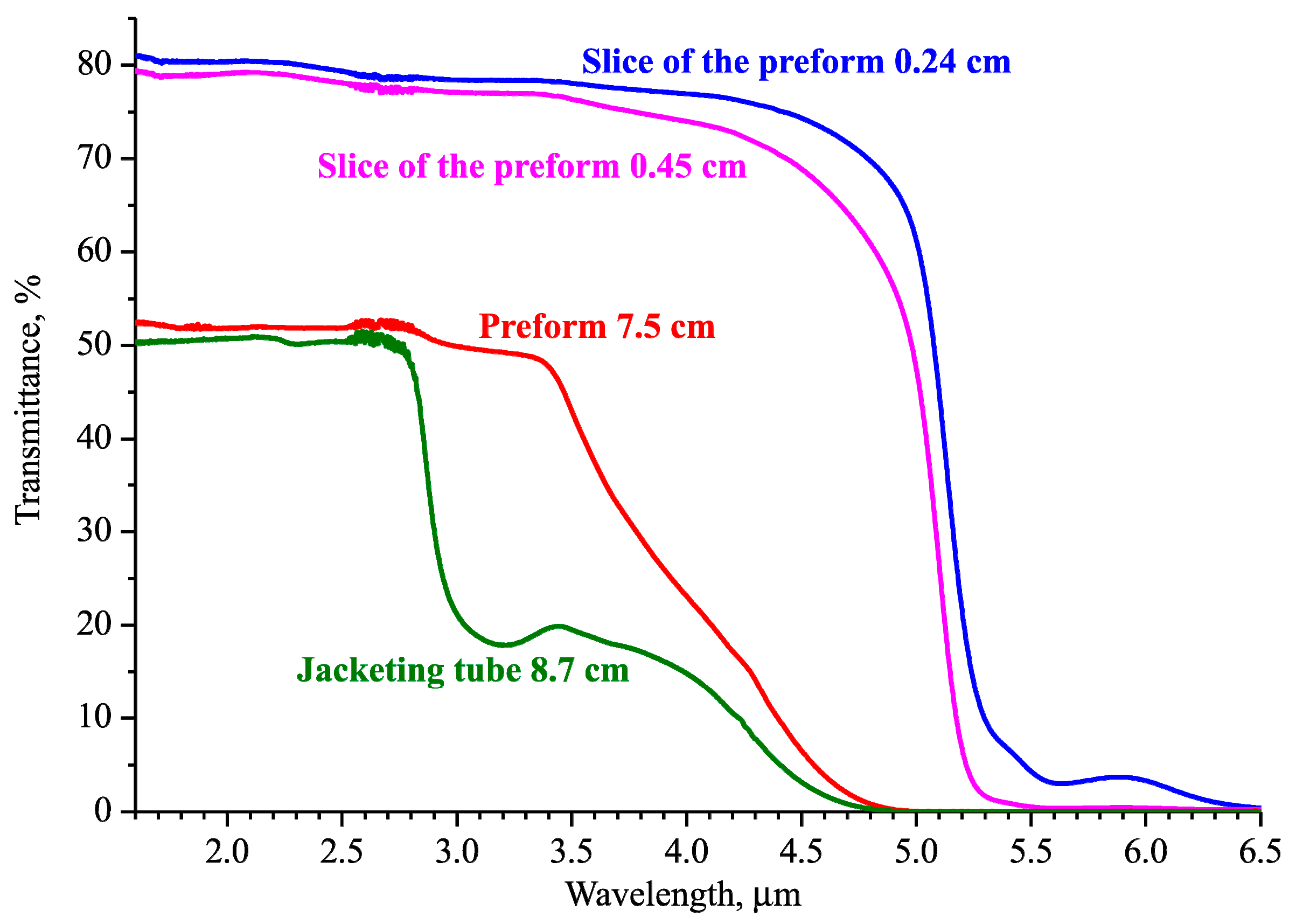
The experimental transmittance spectra of the 7.5 cm long glass preform and of its slices 0.24 cm and 0.45 cm thick in the 1.6–6.5 μm range is plotted in Figure 2. The transmission of the whole jacketing tube 8.7 cm long from “medium hydroxyl” glass is given for comparison of hydroxyl groups absorption. The transmittance in the near-IR for thin slices is limited by the Fresnel reflection on end faces. The transmission of long samples is further limited by the deviation of the radiation beam from the receiver axis, pronounced atmospheric vapor absorption regions of about 2.7 μm occur due to the discrepancy between the path length of the measuring beam when recording the comparison spectrum and the sample spectrum in the Fourier spectrometer. Hydroxyl groups absorption bands almost do not appear in the spectra of thin samples of well-dehydrated preform glass. The main bands with maxima of about 3 μm and 4.4 μm can be distinguished in the spectrum of a 7.5 cm sample. The spectrum of the medium-dehydrated jacket tube glass additionally demonstrates a hydroxyl absorption band with a maximum of 2.3 μm.
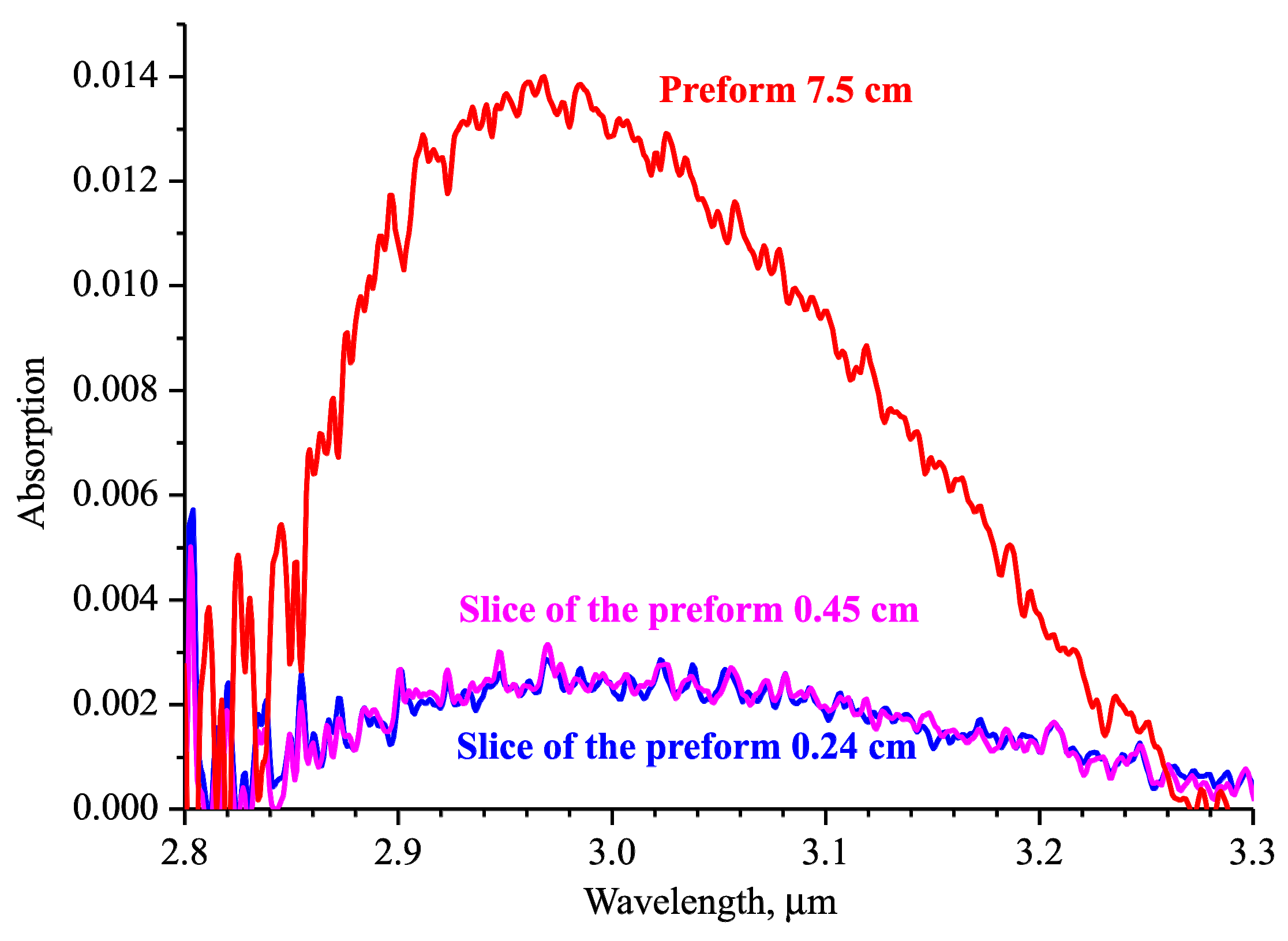
Since the reported tellurite MS fiber was specially designed for use in the range of 3 μm and beyond, it was very important to obtain “low-hydroxyl” glass in order to minimize absorption by hydroxyl groups in the main band near 3 μm. The large length of the initial preform allowed us to process the absorption band near 3 μm and calculate the volume absorption coefficient. The absorption spectra calculated at around 3 μm are plotted in Figure 3. The maximum of absorption for the entire 7.5 cm preform corresponds to 0.0135. For short samples, the absorption values at the maximum of hydroxyl band are the same and are equal to ~0.0025. This can be explained by the fact that the absorption value at the ends of the samples significantly exceeds the volume absorption. Taking the absorption value of 0.0025 as the end absorption and the value of 0.0135 as the total absorption of the 7.5 cm sample, the absorption coefficient can be calculated as follows: α = (0.0135 − 0.0025)/7.5 cm = 0.0015 cm−1. This is equivalent to ~0.65 dB/m of optical loss due to hydroxyl groups in the band maximum near 3 µm. This small value confirms a very low content of hydroxyl groups in the preform prepared. Note that the total loss in fibers always exceeds this level. So, optical loss in the step-index fiber of the similar glass was about 2 dB∕m at the maximum of hydroxyl group absorption at about 3 μm [29].
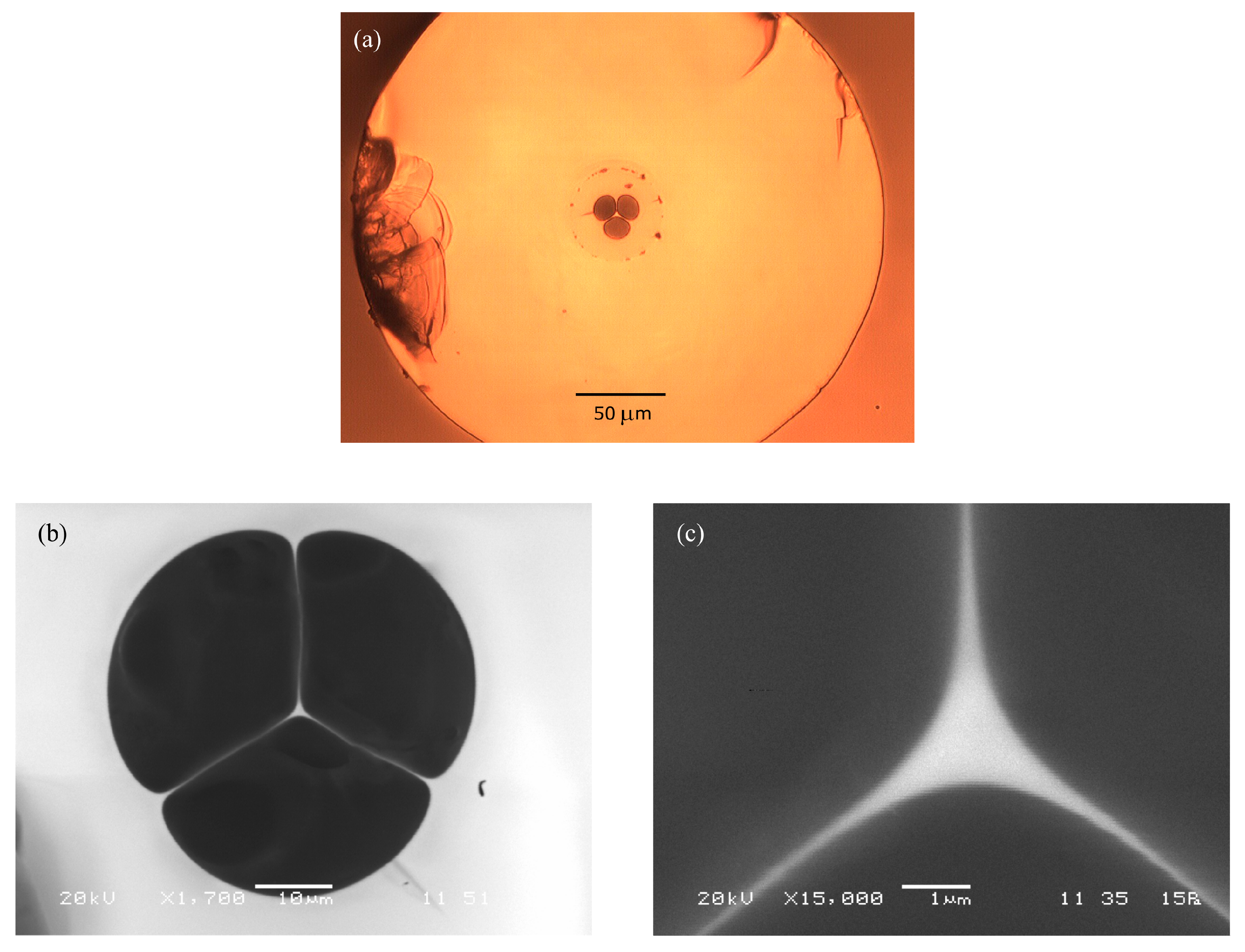
We produced MS fibers with core sizes ranging from 1.5 to 5 μm. A cross-section microphotograph of an MS fiber sample is shown in Figure 4a. This image was obtained with an optical microscope (Motic BA310). The dark part to left of the photo is due to imperfect fiber cleavage. There are also several defects at the round interface between two layers of the preform. Note that these defects do not affect losses for the light propagating through the core. The resolution of the optical microscope is insufficient for detailed visualization of the structure of the core with a diameter of about 1–2 μm and sub-micron walls. For this, the image of the central part of the MS fiber and its core was obtained with an electron microscope (JEOL, JSM-5910LV) (see Figure 4b,c, respectively). These figures demonstrate that the core structure is almost perfect, without defects and distortion of the geometric proportions. Therefore, this fiber is of significant interest for nonlinear light conversion and its properties should be studied and simulated in more detail.

4. Numerical Results

4.1. Dispersion and Nonlinearity of MS Fibers

Next, we performed numerical simulation of the dispersion and nonlinear characteristics of MS fibers. The modeled core cross section is shown in Figure 5a. The core size was characterized by a diameter d of the inscribed circle. Using the numerical methods described in Section 2.2, we calculated the field structure of the fundamental mode and the effective refractive index neff depending on wavelength in the 1.5–6 μm range for different values of d. An example of the longitudinal z-component of the Poynting vector at a wavelength of 2.8 μm for d = 2 μm is shown in Figure 5b.
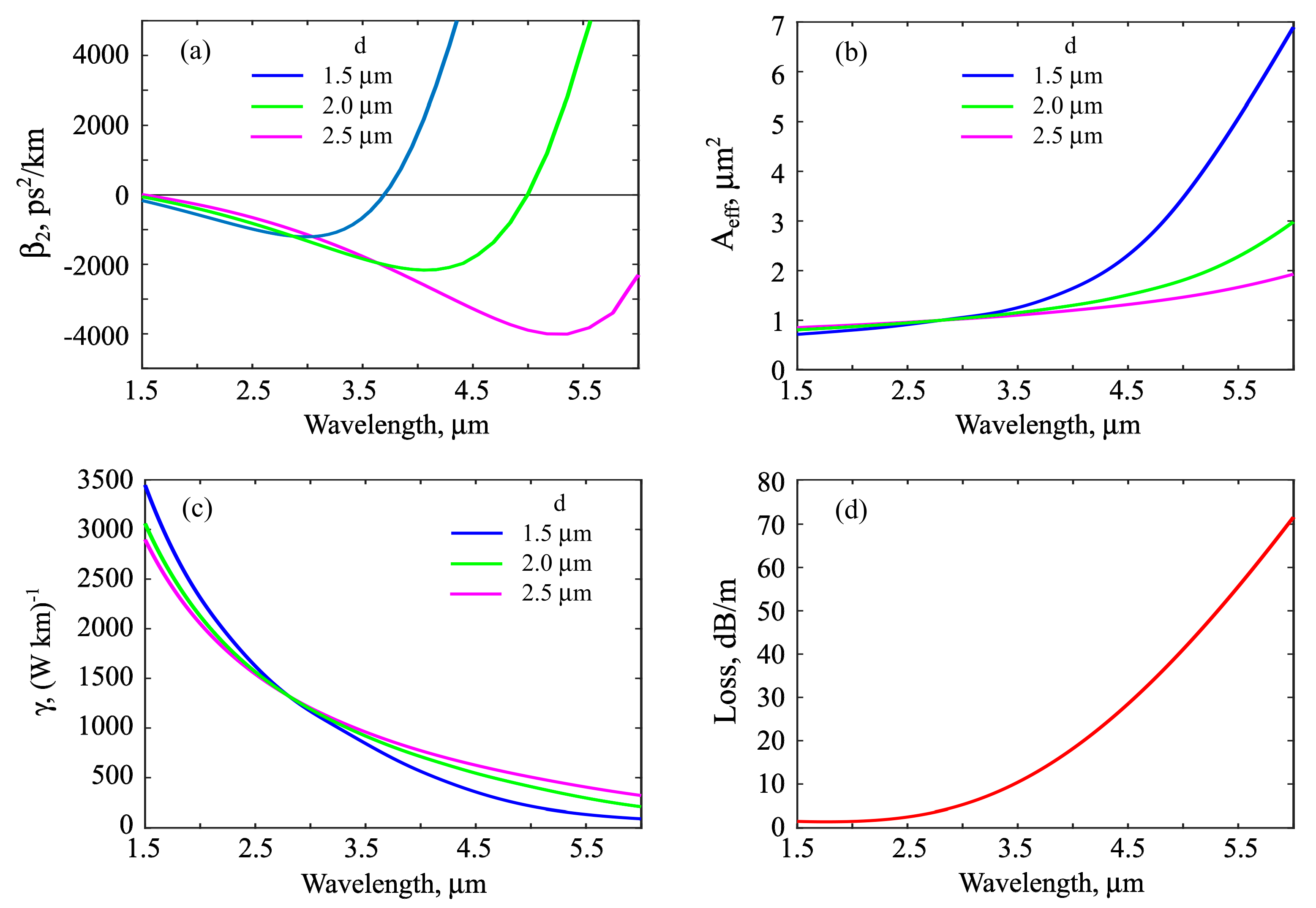
The GVDs as a function of wavelength obtained by Equation (2) for different values of d are plotted in Figure 6a. Due to the strong waveguide contribution, the dispersion of the MS fibers differs significantly from the material dispersion. The zero dispersion wavelength (ZDW) of the considered tellurite glass is ~2.17 μm [29]. For shorter wavelengths, the material dispersion is normal and for longer ones, the material dispersion is anomalous. Microstructuring leads to the appearance of two ZDWs for thin cores, the first of which is noticeably shifted to the short-wavelength range, and the second one is shifted to the long-wavelength range relative to the ZDW of the glass. Due to the strong waveguide contribution, the thinner the MS fiber core, the shorter the second ZDW is.
The effective mode field areas calculated by Equation (3) and the nonlinear Kerr coefficients calculated by Equation (4) are shown in Figure 6b,c, respectively. With increasing wavelength, the effective mode field areas increase, and the nonlinear Kerr coefficients decrease.

4.2. SSFS in MS Fibers

A fundamental soliton in lossless optical fibers with Kerr nonlinearity and anomalous quadratic dispersion and without higher-order effects has the following form [30]:
| A ( z , t ) | 2 = P 0 cosh 2 ( t / T 0 ) ,
where A(z, t) is the slowly varying electric field envelope, z is the distance along the fiber, P0 is the peak power, and T0 is the characteristic duration related to a full width at half maximum (FWHM) duration as
T F W H M = 2 ln ( 1 + 2 ) T 0 1.763 T 0
For the fundamental soliton N = 1, the peak power is determined from the following expression:
N = γ P 0 T 0 2 | β 2 |
The soliton energy W is
W = 2 P 0 T 0
For the SSFS caused by the stimulated intrapulse Raman scattering, the following estimation for the rate of central frequency tuning is obtained within the perturbation theory [30]:
d Ω d z = 8 T R 15 β 2 T 0 4 = T R 30 γ 4 W 4 | β 2 | 3 ,
where Ω is the central soliton frequency, TR is the characteristic Raman response time. Equation (11) is obtained for constant parameters; therefore, it cannot be explicitly used to describe the propagation of ultrashort solitons in tellurite MS fibers with the characteristics strongly depending on wavelengths such as shown in Figure 6. However, Equation (11) can be used for a qualitative understanding of the requirements for MS fibers and input pulses for efficient soliton frequency conversion. As a soliton is propagating along a fiber, its energy decreases both due to optical losses of the fiber and due to losses associated with Raman scattering. A decrease in energy and a decrease in the nonlinear Kerr coefficient at the central wavelength of the Raman soliton lead to a significant slowdown in the SSFS rate. To mitigate these effects and maintain a high rate of central frequency tuning to attain ultrabroadband soliton wavelength conversion, one can use fibers with a dispersion characteristic such that |β2| decreases with wavelength growth. For this reason, the designed tellurite MS fibers with two ZDWs are promising for pulse frequency conversion from 2.8 μm to the range well beyond 3 μm.
Next, numerical simulation of nonlinear pulse conversion was performed using the method described in Section 2.2 for the fiber parameters shown in Figure 6 (including the modeled loss function plotted in Figure 6d. The input signals were 200-fs sech2-shaped pulses with soliton number N > 1. It is well known that, at the initial stage of the evolution of such signals, higher-order soliton compression was observed, accompanied by spectral broadening with a significant decrease in duration of up to a few cycles [30]. After this, a fundamental soliton was formed, with the frequency down-shifted due to intrapulse Raman scattering. If there is enough remaining energy, several solitons can be formed sequentially [29]. Here, we specially chose modeling parameters so that the main part of the energy was contained in the first soliton. We took input pulse energies which should be lower than the damage threshold for the microstructured tellurite fibers [37].
The spectral evolution of a 150-pJ initial pulse in the MS fiber with d = 1.5 μm is shown in Figure 7a, while FWHM duration as a function of a distance along the fiber is plotted in Figure 7b. The fivefold pulse self-compression occurs at the first cm; at the second cm, transition processes take place. After that the soliton is formed and the almost constant rate of SSFS is achieved due to a decrease of |β2| with wavelength increase (up to z~6 cm). Further, the soliton is so close to the ZDW that its long-wavelength wing reaches the region of normal dispersion, and when phase-matching conditions are satisfied, the radiation of a dispersion wave (DW) starts (near z = 7.5 cm, see Figure 7a,b, vertical dashed line). After this, the central frequency of the soliton is stabilized, and its energy decreases continuously both due to fiber losses and due to losses related to the DW radiation. The duration of the soliton increases. In the end, the soliton will be destroyed.
The spectral evolution of a 500-pJ initial pulse in the MS fiber with d = 2 μm presented in Figure 7c is qualitatively similar to the case of d = 1.5 μm described above (compare Figure 7a,c). An almost sevenfold compression down to ~30 fs corresponding to a three-cycle pulse is attained at the first 0.5 cm. The FWHM duration is plotted in Figure 7d. After that, the fundamental Raman soliton is formed and its central wavelength tuning starts. For the distance shorter than 6 cm, the rate of the SSFS slows down, and the soliton duration increases. After passing through the point corresponding to the maximum value of |β2|, the tuning rate increases, and the soliton is shortened until it approaches the ZDW. After that DW generation begins near z ~ 9 cm (see Figure 7c,d, vertical dashed line). The DW wavelength is about 5.5 μm where optical losses are very high (see Figure 6d), so efficient conversion of soliton energy to DW is not reached. The soliton wavelength shift up to 4.8 μm is limited by the ZDW and high loss.
The spectral evolution of a 500-pJ initial pulse in the MS fiber with d = 2.5 μm is presented in Figure 7e and its FWHM duration as a function of z is demonstrated in Figure 7f. After higher-order soliton compression and fundamental soliton formation, the rate of the Raman wavelength shift decreases continuously, and the soliton length increases in time. The soliton wavelength shift is limited by losses and |β2|. The attained central wavelength is shorter than for the MS fiber with d = 2 μm (compare Figure 7c,e).

5. Discussion and Conclusions

We produced experimentally highly nonlinear tellurite MS three-hole fibers with a very low content of hydroxyl groups which is confirmed by a small value of an absorption coefficient α = 0.0015 cm−1 at 3 μm. We calculated dispersion and nonlinearity of the produced fibers using the finite element method. We showed numerically that there are two ZDWs for the core diameter of 2 μm and smaller, which are beneficial for the efficient SSFS using 200-fs pump pulses at 2.8 μm. In a general case, pump pulses can be obtained with solid-state of fiber laser systems and launched into a MS fiber through free space using coupling lenses. Note that, in principle, not only microstructured fibers, but also all-solid W-type fibers allow for obtaining two ZDWs [38], but shifting the second ZDW to the range beyond 3 μm is a separate task. For MS tellurite fibers with two ZDWs, the decrease of |β2| with wavelength increase helps to keep the high SSFS rate. It was found in the numerical simulation, taking into account the actual dispersion profile, the dependence of the nonlinear Kerr coefficient on wavelength, losses, and the Raman nonlinearity, that the central wavelength of a Raman soliton can be shifted up to 4.8 μm for a core size of 2 μm. The presented results should be verified experimentally and after that can be used for designing a fiber laser system generating tunable ultrashort solitons in the mid-IR range well beyond 3 μm for spectroscopic and other applications.

Author Contributions

Conceptualization, E.A.A., S.A.S., A.A.B., and A.V.A.; methodology, E.A.A. and V.V.D.; software, E.A.A.; validation, E.A.A.; formal analysis, E.A.A. and V.V.D.; investigation, E.A.A., V.V.D., S.E.M., and A.F.K.; writing—original draft preparation, E.A.A.; writing—review and editing V.V.D., S.A.S., A.A.B., and A.V.A.; visualization, E.A.A and V.V.D. All authors have read and agreed to the published version of the manuscript.

Funding

This research was funded by the Russian Foundation for Basic Research, grants number 19-29-11032, 18-52-45005, and 19-02-00443; and within the framework of the plan of IChHPS RAS on the state work on fundamental research.

Conflicts of Interest

The authors declare no conflict of interest.

References

  1. Tao, G.; Ebendorff-Heidepriem, H.; Stolyarov, A.M.; Danto, S.; Badding, J.V.; Fink, Y.; Ballato, J.; Abouraddy, A.F. Infrared fibers. Adv. Opt. Photonics 2015, 7, 379–458. [Google Scholar] [CrossRef]
  2. Liu, Z.; Zhang, Z.F.; Tam, H.Y.; Tao, X. Multifunctional smart optical fibers: Materials, fabrication, and sensing applications. Photonics 2019, 6, 48. [Google Scholar] [CrossRef] [Green Version]
  3. Bufetov, I.A.; Kosolapov, A.F.; Pryamikov, A.D.; Gladyshev, A.V.; Kolyadin, A.N.; Krylov, A.A.; Yatsenko, Y.P.; Biriukov, A.S. Revolver hollow core optical fibers. Fibers 2018, 6, 39. [Google Scholar] [CrossRef] [Green Version]
  4. Falconi, M.C.; Laneve, D.; Prudenzano, F. Advances in mid-IR fiber lasers: Tellurite, fluoride and chalcogenide. Fibers 2017, 5, 23. [Google Scholar] [CrossRef] [Green Version]
  5. Dai, S.; Wang, Y.; Peng, X.; Zhang, P.; Wang, X.; Xu, Y. A review of mid-infrared supercontinuum generation in chalcogenide glass fibers. Appl. Sci. 2018, 8, 707. [Google Scholar] [CrossRef] [Green Version]
  6. Petersen, C.R.; Møller, U.; Kubat, I.; Zhou, B.; Dupont, S.; Ramsay, J.; Benson, T.; Sujecki, S.; Abdel-Moneim, N.; Tang, Z.; et al. Mid-infrared supercontinuum covering the 1.4–13.3 μm molecular fingerprint region using ultra-high NA chalcogenide step-index fibre. Nat. Photonics 2014, 8, 830. [Google Scholar] [CrossRef]
  7. Saini, T.S.; Hoa, N.P.T.; Tuan, T.H.; Luo, X.; Suzuki, T.; Ohishi, Y. Tapered tellurite step-index optical fiber for coherent near-to-mid-IR supercontinuum generation: experiment and modeling. Appl. Opt. 2019, 58, 415–421. [Google Scholar] [CrossRef] [PubMed]
  8. Martinez, R.A.; Plant, G.; Guo, K.; Janiszewski, B.; Freeman, M.J.; Maynard, R.L.; Islam, M.N.; Terry, F.L.; Alvarez, O.; Chenard, F.; et al. Mid-infrared supercontinuum generation from 1.6 to >11 μm using concatenated step-index fluoride and chalcogenide fibers. Opt. Lett. 2018, 43, 296–299. [Google Scholar] [CrossRef] [PubMed]
  9. Duval, S.; Gauthier, J.C.; Robichaud, L.R.; Paradis, P.; Olivier, M.; Fortin, V.; Bernier, M.; Piché, M.; Vallée, R. Watt-level fiber-based femtosecond laser source tunable from 2.8 to 3.6 μm. Opt. Lett. 2016, 41, 5294–5297. [Google Scholar] [CrossRef]
  10. Tang, Y.; Wright, L.G.; Charan, K.; Wang, T.; Xu, C.; Wise, F.W. Generation of intense 100 fs solitons tunable from 2 to 4.3 μm in fluoride fiber. Optica 2016, 3, 948–951. [Google Scholar] [CrossRef]
  11. Cheng, T.; Kanou, Y.; Asano, K.; Deng, D.; Liao, M.; Matsumoto, M.; Misumi, T.; Suzuki, T.; Ohishi, Y. Soliton self-frequency shift and dispersive wave in a hybrid four-hole AsSe2-As2S5 microstructured optical fiber. Appl. Phys. Lett. 2014, 104, 121911. [Google Scholar] [CrossRef]
  12. Bi, W.; Li, X.; Xing, Z.; Zhou, Q.; Fang, Y.; Gao, W.; Xiong, L.; Hu, L.; Liao, M. Wavelength conversion through soliton self-frequency shift in tellurite microstructured fiber with picosecond pump pulse. J. Appl. Phys. 2016, 119, 043102. [Google Scholar] [CrossRef]
  13. Koptev, M.Y.; Anashkina, E.A.; Andrianov, A.V.; Dorofeev, V.V.; Kosolapov, A.F.; Muravyev, S.V.; Kim, A.V. Widely tunable mid-infrared fiber laser source based on soliton self-frequency shift in microstructured tellurite fiber. Opt. Lett. 2015, 40, 4094–4097. [Google Scholar] [CrossRef] [PubMed]
  14. Zhang, L.; Cheng, T.; Deng, D.; Sega, D.; Liu, L.; Xue, X.; Suzuki, T.; Ohishi, Y. Tunable soliton generation in a birefringent tellurite microstructured optical fiber. IEEE Photonics Technol. Lett. 2015, 27, 1547–1549. [Google Scholar] [CrossRef]
  15. Domachuk, P.; Wolchover, N.A.; Cronin-Golomb, M.; Wang, A.; George, A.K.; Cordeiro, C.M.B.; Knight, J.C.; Omenetto, F.G. Over 4000 nm bandwidth of mid-IR supercontinuum generation in sub-centimeter segments of highly nonlinear tellurite PCFs. Opt. Express 2008, 16, 7161–7168. [Google Scholar] [CrossRef] [PubMed] [Green Version]
  16. Thapa, R.; Rhonehouse, D.; Nguyen, D.; Wiersma, K.; Smith, C.; Zong, J.; Chavez-Pirson, A. Mid-IR supercontinuum generation in ultra-low loss, dispersion-zero shifted tellurite glass fiber with extended coverage beyond 4.5 μm. In Technologies for Optical Countermeasures X; And High-Power Lasers 2013: Technology and Systems; International Society for Optics and Photonics: Bellingham, WA, USA, 2013; Volume 8898, p. 889808. [Google Scholar] [CrossRef]
  17. Kedenburg, S.; Strutynski, C.; Kibler, B.; Froidevaux, P.; Désévédavy, F.; Gadret, G.; Jules, J.-C.; Steinle, T.; Mörz, F.; Steinmann, A.; et al. High repetition rate mid-infrared supercontinuum generation from 1.3 to 5.3 μm in robust step-index tellurite fibers. JOSA B 2017, 34, 601–607. [Google Scholar] [CrossRef]
  18. Mirov, S.B.; Moskalev, I.S.; Vasilyev, S.; Smolski, V.; Fedorov, V.V.; Martyshkin, D.; Peppers, J.; Mirov, M.; Dergachev, A.; Gapontsev, V. Frontiers of mid-IR lasers based on transition metal doped chalcogenides. IEEE J. Sel. Top. Quantum Electron. 2018, 24, 1601829. [Google Scholar] [CrossRef]
  19. Duval, S.; Bernier, M.; Fortin, V.; Genest, J.; Piché, M.; Vallée, R. Femtosecond fiber lasers reach the mid-infrared. Optica 2015, 2, 623–626. [Google Scholar] [CrossRef]
  20. Gu, H.; Qin, Z.; Xie, G.; Hai, T.; Yuan, P.; Ma, J.; Qian, L. Generation of 131 fs mode-locked pulses from 2.8 μm Er:ZBLAN fiber laser. Chin. Opt. Lett. 2020, 18, 031402. [Google Scholar] [CrossRef]
  21. Antipov, S.; Hudson, D.D.; Fuerbach, A.; Jackson, S.D. High-power mid-infrared femtosecond fiber laser in the water vapor transmission window. Optica 2016, 3, 1373–1376. [Google Scholar] [CrossRef] [Green Version]
  22. Anashkina, E.A.; Koptev, M.Y.; Andrianov, A.V.; Dorofeev, V.V.; Singh, S.; Leuchs, G.; Kim, A.V. Reconstruction of optical pulse intensity and phase based on SPM spectra measurements in microstructured tellurite fiber in telecommunication range. J. Lightwave Technol. 2019, 37, 4375–4381. [Google Scholar] [CrossRef]
  23. Pakarzadeh, H.; Forghani, S.E.; Amiri, I.S. Propagation of telecommunication pulses in photonics nanowires: A comparative physics study. Results Phys. 2019, 13, 102342. [Google Scholar] [CrossRef]
  24. Cheng, T.; Zhang, F.; Tanaka, S.; Li, S.; Yan, X.; Zhang, X.; Suzuki, T.; Ohishi, Y. Ultrafast all-optical signal modulation induced by optical Kerr effect in a tellurite photonic bandgap fiber. Photonics 2019, 6, 113. [Google Scholar] [CrossRef] [Green Version]
  25. Dianov, E.M. Fibre optics: Forty years later. Quantum Electron. 2010, 40, 1. [Google Scholar] [CrossRef]
  26. Senkans, U.; Braunfelds, J.; Lyashuk, I.; Porins, J.; Spolitis, S.; Bobrovs, V. Research on FBG-Based Sensor Networks and Their Coexistence with Fiber Optical Transmission Systems. J. Sens. 2019, 2019, 6459387. [Google Scholar] [CrossRef] [Green Version]
  27. Anashkina, E.A.; Dorofeev, V.V.; Koltashev, V.V.; Kim, A.V. Development of Er3+-doped high-purity tellurite glass fibers for gain-switched laser operation at 2.7 μm. Opt. Mater. Express 2017, 7, 4337–4351. [Google Scholar] [CrossRef]
  28. Anashkina, E.A.; Dorofeev, V.V.; Muravyev, S.V.; Motorin, S.E.; Andrianov, A.V.; Sorokin, A.A.; Koptev, M.Y.; Singh, S.; Kim, A.V. Possibilities of laser amplification and measurement of the field structure of ultrashort pulses in the range of 2.7–3 μm in tellurite glass fibres doped with erbium ions. Quantum Electron. 2018, 48, 1118–1127. [Google Scholar] [CrossRef]
  29. Anashkina, E.A.; Andrianov, A.V.; Dorofeev, V.V.; Kim, A.V. Toward a mid-infrared femtosecond laser system with suspended-core tungstate-tellurite glass fibers. Appl. Opt. 2016, 55, 4522–4530. [Google Scholar] [CrossRef]
  30. Agrawal, G.P. Nonlinear Fiber Optics, 6th ed.; Elsevier: Amsterdam, The Netherlands, 2019. [Google Scholar]
  31. Foster, M.A.; Moll, K.D.; Gaeta, A.L. Optimal waveguide dimensions for nonlinear interactions. Opt. Express 2004, 12, 2880–2887. [Google Scholar] [CrossRef] [Green Version]
  32. Laegsgaard, J. Mode profile dispersion in the generalized nonlinear Schrödinger equation. Opt. Express 2007, 15, 16110–16123. [Google Scholar] [CrossRef]
  33. Anashkina, E.A.; Shiryaev, V.S.; Koptev, M.Y.; Stepanov, B.S.; Muravyev, S.V. Development of As-Se tapered suspended-core fibers for ultra-broadband mid-IR wavelength conversion. J. Non Cryst. Solids 2018, 480, 43–50. [Google Scholar] [CrossRef]
  34. Anashkina, E.A.; Shiryaev, V.S.; Snopatin, G.E.; Muraviev, S.V.; Kim, A.V. On the possibility of mid-IR supercontinuum generation in As-Se-Te/As-S core/clad fibers with all-fiber femtosecond pump source. J. Non Cryst. Solids 2018, 480, 38–42. [Google Scholar] [CrossRef] [Green Version]
  35. Yan, X.; Qin, G.; Liao, M.; Suzuki, T.; Ohishi, Y. Transient Raman response effects on the soliton self-frequency shift in tellurite microstructured optical fiber. JOSA B 2011, 28, 1831–1836. [Google Scholar] [CrossRef]
  36. Anashkina, E.A.; Sorokin, A.A.; Marisova, M.P.; Andrianov, A.V. Development and numerical simulation of tellurite glass microresonators for optical frequency comb generation. J. Non Cryst. Solids 2019, 522, 119567. [Google Scholar] [CrossRef]
  37. Liao, M.; Gao, W.; Duan, Z.; Yan, X.; Suzuki, T.; Ohishi, Y. Directly draw highly nonlinear tellurite microstructured fiber with diameter varying sharply in a short fiber length. Opt. Express 2012, 20, 1141–1150. [Google Scholar] [CrossRef] [PubMed]
  38. Huang, Y.; Zhou, N.; Li, Q.; Jia, Z.; Wang, F.; Qin, W.; Zhang, D.; Qin, G. Design of all-solid W-type index fluorotellurite fibers with near-zero-flattened chromatic dispersion for optical frequency comb generation. Appl. Opt. 2019, 58, 8852–8857. [Google Scholar] [CrossRef] [PubMed]
Figure 1. A photography of the 7.5 cm long glass preform and a view through the entire preform on the wall of the neighboring building.
Photonics 07 00051 g001
Figure 2. IR transmission spectra of the preform (L = 7.5 cm), jacketing tube (L = 8.7 cm), and two slices of the preform (L = 0.24 cm and L = 0.45 cm).
Photonics 07 00051 g002
Figure 3. Absorption spectra within hydroxyl groups band of the 7.5 cm long preform and of the slices 0.24 cm and 0.45 cm thick.
Photonics 07 00051 g003
Figure 4. (a) Cross-section of MS fiber obtained with optical microscope. Cross section of the central part of MS fiber (b) and fiber core (c) obtained with electron microscope. Light areas correspond to glass and dark areas correspond to air holes.
Photonics 07 00051 g004
Figure 5. (a) Modeled cross section of MS fibers used in numerical simulation. (b) Simulated z-component of Poynting vector for d = 2 μm at a wavelength of 2.8 μm.
Photonics 07 00051 g005
Figure 6. Calculated GVDs (a), effective mode field areas (b), and nonlinear coefficients (c) as a function of wavelength for MS fibers with diameters d = 1.5, 2, and 2.5 μm. (d) The modeled loss function used in numerical simulation of pulse conversion.
Photonics 07 00051 g006
Figure 7. Evolution of spectral intensity and pulse duration of initial 200-fs sech2-shape signal during propagation in MS fibers for d = 1.5 μm (a,b), respectively; for d = 2 μm (c,d), respectively; and for d = 2.5 μm (e,f), respectively. Initial pulse energy is 500 pJ for d = 2 μm and d = 2.5 μm and 150 pJ for d = 1.5 μm.
Photonics 07 00051 g007
Table 1. Sellmeier constants of tellurite glass.
C1C2C3C4, μm2C5, μm2
2.49098661.95150373.02125920.056740339225