Article

A Programmable Mode-Locked Fiber Laser Using Phase-Only Pulse Shaping and the Genetic Algorithm

1
College of Engineering and Technology, American University of the Middle East, Kuwait
2
Electronics Engineering Department, Hijjawi Faculty for Engineering Technology, Yarmouk University, Irbid 21163, Jordan
*
Author to whom correspondence should be addressed.
Photonics 2020, 7(3), 69; https://doi.org/10.3390/photonics7030069
Submission received: 24 July 2020 / Revised: 20 August 2020 / Accepted: 2 September 2020 / Published: 4 September 2020

Abstract

:
A novel, programmable, mode-locked fiber laser design is presented and numerically demonstrated. The laser programmability is enabled by an intracavity optical phase-only pulse shaper, which utilizes the same linearly chirped fiber Bragg grating (LC-FBG) from its two opposite ends to perform real-time optical Fourier transformation. A binary bit-pattern generator (BPG) operating at 20-Gb/s and producing a periodic sequence of 32 bits every 1.6 ns, is subsequently used to drive an optical phase modulator inside the laser cavity. Simulation results indicate stable programmable intensity profiles for each optimized user defined 32 code words. The laser operated in the self-similar mode-locking regime, enabling wave-breaking free operation. The programmable 32 bit code word targeting a specific intensity profile was determined using 100 generations of the genetic algorithm. The control of ultrashort pulse intensity profiles on the picosecond and femtosecond time scales is difficult. The process of stretching and compressing the pulse in the time domain allows for a slower BPG to impose a predefined phase modulation prior to pulse compression. This results in control over the fine features of the intensity profile of the compressed pulse on a picosecond or femtosecond time scale inside the laser cavity. The stability of the proposed scheme depends on the consistency and accuracy of the BPG rise and fall times in practice.

Graphical Abstract

1. Introduction

The development of lasers and their reliable generation of ultrashort optical pulses on the picosecond and femtosecond time scale, have found a multitude of applications ranging from astronomy [1], to elemental mass spectrometry [2] and to telecommunications [3]. Ever since, there has been continued interest in the control and synthesis of optical pulses through programmable means enabling the generation of nearly arbitrary user defined complex waveforms. Recently, numerical modeling of passively mode-locked fiber lasers showed the generation of super Gaussian intensity profiles by changing the intensity discriminating mechanism inside the laser cavity from a saturable absorber (SA) to a long period fiber grating (LPFG) [4]. Although the work in [4] demonstrated the ability to change the pulse shapes from self-similar parabolic pulses to super Gaussian pulses, it offered no programmability. In [5], a programmable, mode-locked fiber laser was demonstrated through introducing a digital micromirror device (DMD)-based arbitrary spectrum amplitude shaper inside the cavity of the laser. Furthermore, the generation of high-fidelity femtosecond pulses has been experimentally demonstrated with a frequency domain pulse shaper [6]. Recently, a mode-locked fiber laser with an e-controlled cavity operating in the ultra wide range was demonstrated [7]. The first demonstration of a programmable fiber-semiconductor laser was recently reported [8]. The primary objective of this paper is to introduce and numerically demonstrate a novel design for a digitally programmable, mode-locked fiber laser, which utilizes time-domain phase-only pulse shaping inside the laser cavity.
The earliest attempt at pulse shaping was the process of pulse compression, which can now reduce a pulse width to less than 6 fs [9]. The process of pulse shaping entails the precise synthesis and control of the optical pulse intensity profile as a function of time. The seminal work by Weiner et al. [10] showed the possibility of pulse shaping through the spatial modulation of the dispersed optical pulse spectrum. Weiner’s approach utilizes a set of diffraction gratings, lenses and a spatially patterned mask, which was later replaced by a programmable spatial light modulator (SLM) [11]. In essence, ultrashort pulses are synthesized by means of parallel manipulation of the amplitude and phase of the optical Fourier components. This frequency domain approach has been revolutionized through line-by-line pulse shaping, in which spectral comb lines resulting from a mode-locked laser are resolved and manipulated individually [12,13], thereby utilizing the advantages of frequency comb and frequency domain pulse shaping simultaneously, allowing the control of more than 100 comb lines at 5 GHz line spacing [14]. However, the disadvantage of this approach is its limited compatibility with optical fiber communication systems, prompting the use of passive fiber devices for pulse shaping, such as fiber Bragg gratings (FBGs) [15] and long-period fiber gratings (LPFGs) [4,16,17]. For example, an LPFG-based flat-top pulse shaper has been used in demultiplexing a 320 Gb/s optical time division multiplexing signal [18]. Although the grating approach is compatible with that of the optical fiber, it is has limited programmability. Furthermore, the direction of research has been driven towards phase-only spatial filters, which avoid the loss associated with amplitude filtering [10]. In addition, only the target intensity profile is needed, while the target phase is unconstrained, thereby increasing the number of degrees of freedom available for filter design.
Programmable, fiber-based, phase-only spectral filtering was introduced for pulse shaping in [19,20,21]. The key concept behind these systems is the utilization of frequency-to-time conversion [22]. A time domain pulse shaping set-up employs the fiber’s temporal dispersion instead of spatial dispersion to map the amplitude spectrum of the pulse into the time domain, while electro-optic (EO) phase modulators are used for filtering [19] as depicted in Figure 1. This time domain filtering approach is technically challenging due to the need for exact dispersion compensation. However, this has been overcome through utilizing the same linearly chirped FBG (LC-FBG) from its two opposite ends as the input and output of the dispersive element [23]. The following sections of this paper explore the theoretical possibility of applying the time-domain pulse shaping set-up in Figure 1 for an interacavity programmable actively mode-locked fiber laser.

2. Principle of Operation

The pulse shaping set-up in [23] can be used in mode-locked fiber lasers. The introduction of an interacavity pulse shaper would affect both laser stability and pulse shape structure. The schematic diagram of the proposed fiber laser design is shown in Figure 2. The laser cavity, without the phase-only optical pulse shaper, used in this investigation, follows the work in [4,24] with the parameters chosen for parabolic pulse generation [25]. In this study, we model an erbium (Er) doped fiber laser in ring cavity configuration. The system can be divided into two sections: (a) the basic laser cavity and (b) the phase-only time domain pulse shaper.

2.1. Basic Laser Cavity

The basic laser cavity (excluding the pulse shaper) is shown in Figure 2a. The cavity is composed of a short section (30 cm) of erbium doped fiber amplifier (EDFA), followed by a saturable absorber (SA), an output coupler (OC) (10%), a short section (30 cm) of dispersion compensating fiber (DCF) and a large section (1 m) of single mode fiber (SMF). The majority of the cavity is formed by the SMF with a normal group velocity dispersion (GVD). Amplification is provided by the EDFA, while the DCF provides negative dispersion [4,17]. Propagation within the EDFA, DCF and SMF sections is modeled by the complex Ginzburg–Landau equation (CGLE) [26]:
i U ξ + i Γ U 1 2 sgn ( β 2 ) 2 U τ 2 = i G ( ξ ) 1 + τ Ω 2 τ 2 U N 2 | U | 2 U
where U denotes the slowly varying envelope approximation (SVEA) of the electric field normalized by the peak field power P 0 , ξ is the distance the pulse travels in the cavity normalized to the dispersion length L D and τ denotes the local time in the rest frame of the mode-locked pulse normalized by the full width at half maximum (FWHM) of T 0 /1.76. The parameter Γ denotes the fiber loss, β 2 denotes second-order dispersion and τ Ω denotes the normalized gain bandwidth. The normalization variables and system modeling parameters are listed in Table 1 [27]. As the dominant GVD is normal due to the larger section of SMF, the total net cavity dispersion is β n e t = 0.014 ps 2 allowing self-similar mode-locking [25]. The parameter N in Equation (1) is given by N = ( γ P 0 T 0 2 / | β 2 | ) 1 / 2 and is normalized to 1 for fundamental soliton formation [27]. The saturable EDFA gain is given by [28]:
G ( ξ ) = 2 G 0 1 + | | U ( ξ ) | | 2 E s a t
where G 0 = 10 is the normalized saturated gain corresponding to a gain of 23 m 1 (due to laser pump). The term E s a t is the normalized saturation energy and τ Ω = 1 / Ω 2 T 0 2 is the normalized gain bandwidth where Ω denotes the FWHM bandwidth of the laser gain. The normalized energy of the current pulse is | | U ( ξ ) | | 2 = | U ( ξ ) | 2 d τ . The standard SA transfer function is modeled with transmittance T = 1 l 0 / [ 1 + P ( τ ) / P s a t ] , where the unsaturated loss l 0 = 0.3, the instantaneous power is denoted P ( τ ) and the saturation power is assumed to be P s a t = 15 kW [16].

2.2. Phase-Only Pulse Shaper

Temporal pulse shaping using time domain filtering is equivalent to frequency domain pulse shaping, as all-fiber temporal dispersion is used instead of spatial dispersion and an electro-optic (EO) modulator acts as a filter or mask. A block diagram of time domain pulse shaping is shown in Figure 1. Essentially, a first-order dispersive element with high chromatic dispersion coefficient β 2 is used to temporally stretch the input pulse over a time window, hence mapping the amplitude spectrum to the time domain [20,23]. The EO phase modulator is then driven by a binary signal and acts as a phase-only filter over the stretched pulse. Finally, another first-order dispersive element with an exactly opposite chromatic dispersion coefficient β 2 is used to compress back the output pulse. Mathematically, the effect of the GVD experienced in both dispersive stages can be modeled as:
e o u t ( t ) = F T 1 exp i 2 β 2 z ω 2 F T e i n ( t )
where z is the length of the dispersive element; ω is the frequency axis; e o u t ( t ) and e i n ( t ) are the output and input pulses from/to the dispersive element, respectively. The symbols F T and F T 1 denote both forward and inverse Fourier transforms, respectively. The main disadvantage of the configuration shown in Figure 1 is the need for exact compensation in the pulse compression stage. This can be overcome by utilizing the same LC-FBG from its two opposite ends as the input and output of the dispersive element [23] as depicted in Figure 2b. The first dispersive stage is performed through propagating the pulses through a LC-FBG incorporating a tunable mechanical rotator permitting different values for the chromatic dispersion coefficient [23]. By setting the rotation angle to θ = 3 a dispersion coefficient of 480 ps/nm over a 3 dB reflection bandwidth of 2.3 nm is obtained [23]. The temporally stretched pulses (exiting from port 3 of the circulator) are then routed through to the EO phase modulator (PM). The PM is driven by the bit-pattern generator (BPG), which generates a user specific code word at 20-Gb/s and a period of 1.6 ns [23]. The 1.6 ns time window is divided into 32 bins of 50 ps width, with each bin experiencing a π / 2 or π / 2 phase shift. As the total cavity length excluding the pulse shaper is 1.6 m, 20 ps parabolic pulses are generated each 5.3 ns, allowing room for the 1.6 ns needed for the pulse shaping.

3. Simulation Results

3.1. Test Codewords

The laser cavity studied here operates in the self-similar mode-locking regime enabling wave-breaking free operation. The simulations employed the split-step Fourier method (SSFM) [28,29]. The SSFM numerical method relies on separating the CGSLE into a linear operator and a nonlinear operator. The linear operator accounts for absorption, saturable gain in the EDFA and second-order dispersion. The nonlinear operator accounts for nonlinearity induced during pulse propagation. Generally, both linear and nonlinear effects operate simultaneously along the propagation distance. However, the SSFM approximates the solution to the CGSLE through assuming that absorption, gain and dispersion operate together, while nonlinearity operates separately over a short fiber distance. Additional details related to the principle and implementation of the SSFM can be found in [28,29]. The numerical simulations employed an in-house tool developed with C programming language.
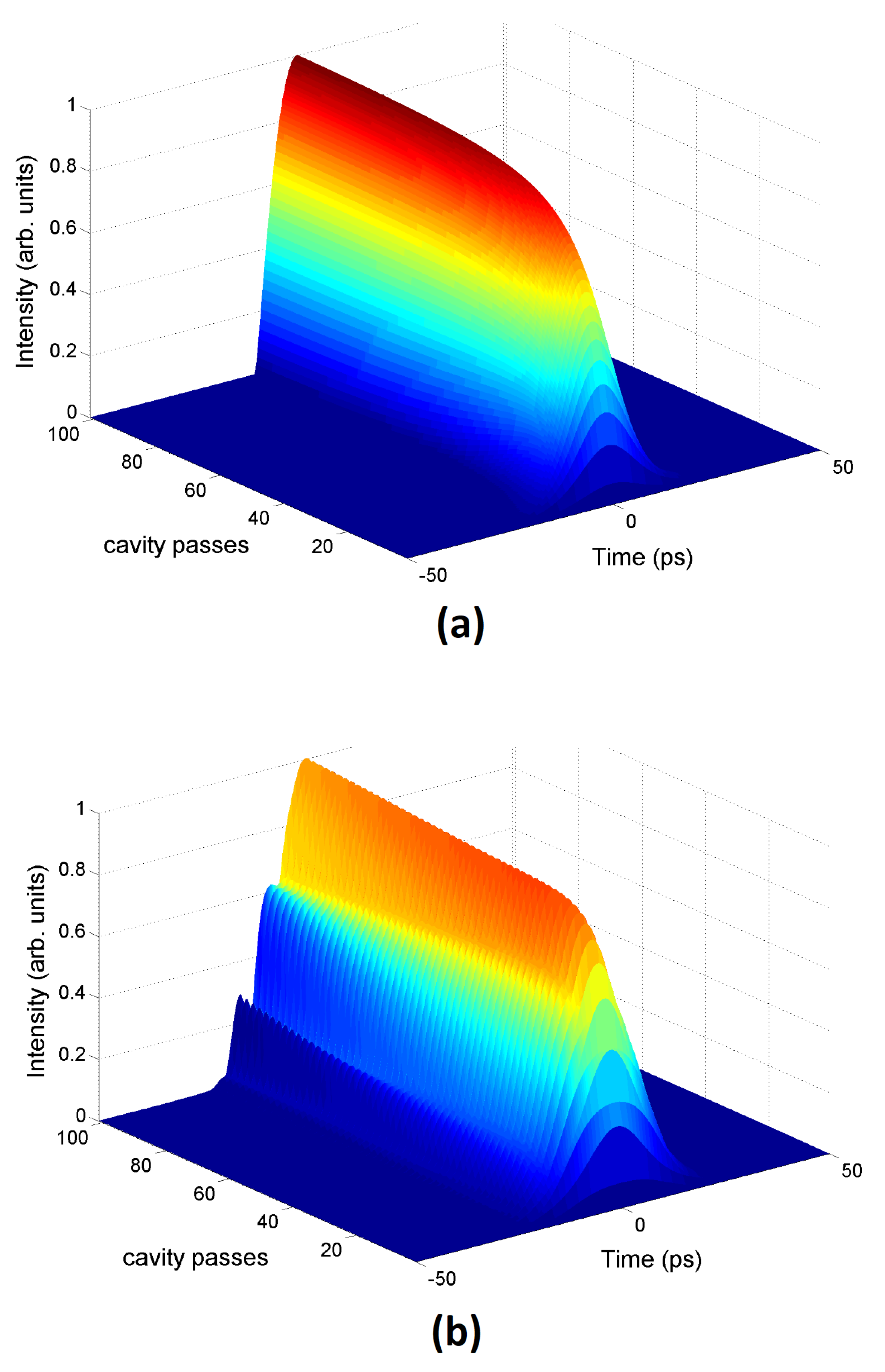
In absence of pulse shaping. a parabolic intensity profile is generated as shown in Figure 3a, and two examples of pulse shapes that can be produced by interacavity pulse shaping are shown in Figure 3b,c, with the binary phase-only modulation sequences of {1 0 1 1 0 0 0 0 0 0 0 0 0 0 1 1 1 1 0 0 0 0 0 0 0 0 0 0 1 1 0 1} and {1 1 1 1 1 0 0 1 0 0 1 1 1 1 1 1 1 1 1 1 0 0 1 1 1 0 0 1 1 1 1 1}, respectively. The pulse shaping process was started with the laser cavity and a random choice of the phase modulation was imposed as oppose to an optimization algorithm. The pulse intensity profile in Figure 3 demonstrates a soliton-like pulse obtained under high cavity gain. Thus, the interacavity pulse shaper can, in theory, sustain soliton-like pulses without wave-breaking. Although the results in Figure 3 are not optimized to any particular target, they show the potential of this approach for controlling the cavity pulse shape. For example, two sub-pulses can be generated on either side of a parabolic profile as shown in Figure 3c. The evolutions of the parabolic intensity profile with and without pulse shaping are shown in Figure 4a,b, respectively.
Although the pulse energy is maintained through phase-only pulse shaping, this is not the case within the laser cavity, as interaction with the saturable absorber is dependent on the shape of the intensity profile. This unique property of the proposed design could be used in suppressing instabilities in the laser cavity, such as period doubling and chaos [17,30].

3.2. Optimization Methods

The previous section illustrated two test code words and their corresponding mode-locked pulse intensity profiles. The process of identifying the required binary phase modulation to attain a pre-defined target intensity profile is not trivial and requires the use of optimization methods, unless the target intensity profile is coincidentally an outcome of phase-only filtering [31]. These optimization algorithms must be able to find the global optimum in a multidimensional parameter space. In this work, attention has been paid to the brute force Monte Carlo method, the iterative Fourier transform method [31,32], the simulated annealing method [10] and the genetic algorithm method [33]. The genetic algorithm was found to outperform the rest in computational speed and accuracy and has been utilized in optimizing the results presented in this subsection. The objective function was defined as the mean of the intensity difference between the target and the shaped pulse in the time domain [32].

3.3. Genetic Algorithm Method

Evolutionary algorithms emulate the process of natural selection, mutation and recombination [34]. The method description and notation follows closely the work presented in [33]. The simulation starts with a set of guesses or codes (vectors) which are selected based on random chance or intelligent guesses. The pool of initial vectors is called a population and each vector within it is called an individual, in analogy to evolution in nature [33]. In this study, the number of individuals in the population P is kept constant throughout the simulation. Here, each individual is represented by a code or vector x while each element or pixel is represented by x. Assuming N pixels per individuals the population can be expressed as:
x j R N , j = 1 , , N
x i R , i = 1 , , N
The first step in the process is selection. In this step, the objective function of each individual is evaluated, where the vector with the smallest value is deemed to be the “fittest” in a biological sense. A deterministic selection rule is applied, by which the fittest m individuals are chosen from the total number of P codes in the population to participate in generating new offspring (new search points) [33,34]. The second step involves generating offspring through recombination and mutation processes.
For recombination a pair is selected randomly from the set of m individuals. The elements of each of those pairs are mixed in a certain way to produce children vectors. For example, we assume M = x 1 , , x m are the set of codes with the m best fitness values. Two parent vectors x j , x j M are chosen such that j j . Single-point cross-over is done through randomly selecting an index i with 1 i N . The index i is the cross-over point, and the child vector y is then [33]:
y i = x j i , i i x j i , i > i
Two-point cross-over is realized through randomly selecting two indices i , i with 1 i < i N . Then the child vector y is expressed as [33]:
y i = x j i , 1 i i x j i , i < i < i x j i , i i N
In multiple-point crossover a random sequence r is generated with elements r i 0 , 1 , where i = 1 , , N and with equal probability for both 0 and 1. Essentially, P ( 0 ) = P ( 1 ) = 0.5 . The child vector y is then [33]:
y i = x j i , r i = 0 x j i r i = 1
Finally, intermediate recombination is done through averaging the elements of each of the parent vectors as [33]:
y = x j + x j 2
The third and final step is mutation, in which a random change of the values of the vector elements is induced [34]. The probability of such a random change occurring will be denoted by P m u t . To model this process a random sequence r is generated with elements r i 0 , 1 , where i = 1 , , N , with P ( 1 ) = P m u t and P ( 0 ) = 1 P m u t .
The new vector y is then given by [33]:
y i = x i + σ m i r i = 0 x i r i = 1
In essence, a random perturbation of the elements of the vector is experienced when 1 appears in the random sequence r. The two quantities σ and m i appearing in Equation (10) are the mutation step size and mutation factor respectively. The mutation factor is a random variable normally distributed around zero [33]:
P m i = 1 2 π exp m i 2 2
The step length σ determines the amount of mutation and is a very important simulation parameter [34]. The larger the value of σ the wider the parameter space and the more scattered the search points [33]. It is advantageous to relate σ to the number of successful mutations in the previous generation [35]. For example, if at generation t the step length is σ t , the value of the step length in generation t + 1 should reflect the number of successful mutations in generation t. This number is indicative of the fact that the search is in a region of space where changes are more likely to produce better fitness values. Mathematically, the mutation efficiency is [33]:
η = n s u c n t o t
where n s u c denotes the number of successful individuals due to mutation in generation t and n t o t is the total number of offspring due to mutation. The step length σ is related to the mutation efficiency η through the following equation [33]:
σ t + 1 = σ t q η η c σ t / q η > η c
where 0 η c 1 is a cut-off threshold which decides on whether the value of σ t + 1 should be increased or decreased and 0 < q < 1 is the contraction factor [33]. A value of η c close to 1 would result in the algorithm being trapped in a local minima as the step length continually decreases. However, a small cut-off threshold would result in larger step sizes and the optimization method does not converge.
Following the simulation parameters in [33] and the physical system in [23], the population number was fixed to P = 48 individuals, of which m = 8 were selected for generating offspring. Each selected individual produced six new offspring (two by recombination and four by mutation) [33]. The choice of recombination method is randomly done per parent. The new set of offspring 8 × 6 would replace the whole population as a seed to the next generation. The best fit candidate was not moved to the subsequent generation; i.e., cloning was not adapted. The mutation probability was set to P m u t = 0.1 and N = 32 pixels were used per individual, with each pixel value unconstrained. The initial step length was set to σ 0 = 100 , the contraction factor q = 0.9 and cut-off threshold η c = 0.3 . The optimization method would run until the worst individual is close enough to the best individual within a tolerance.
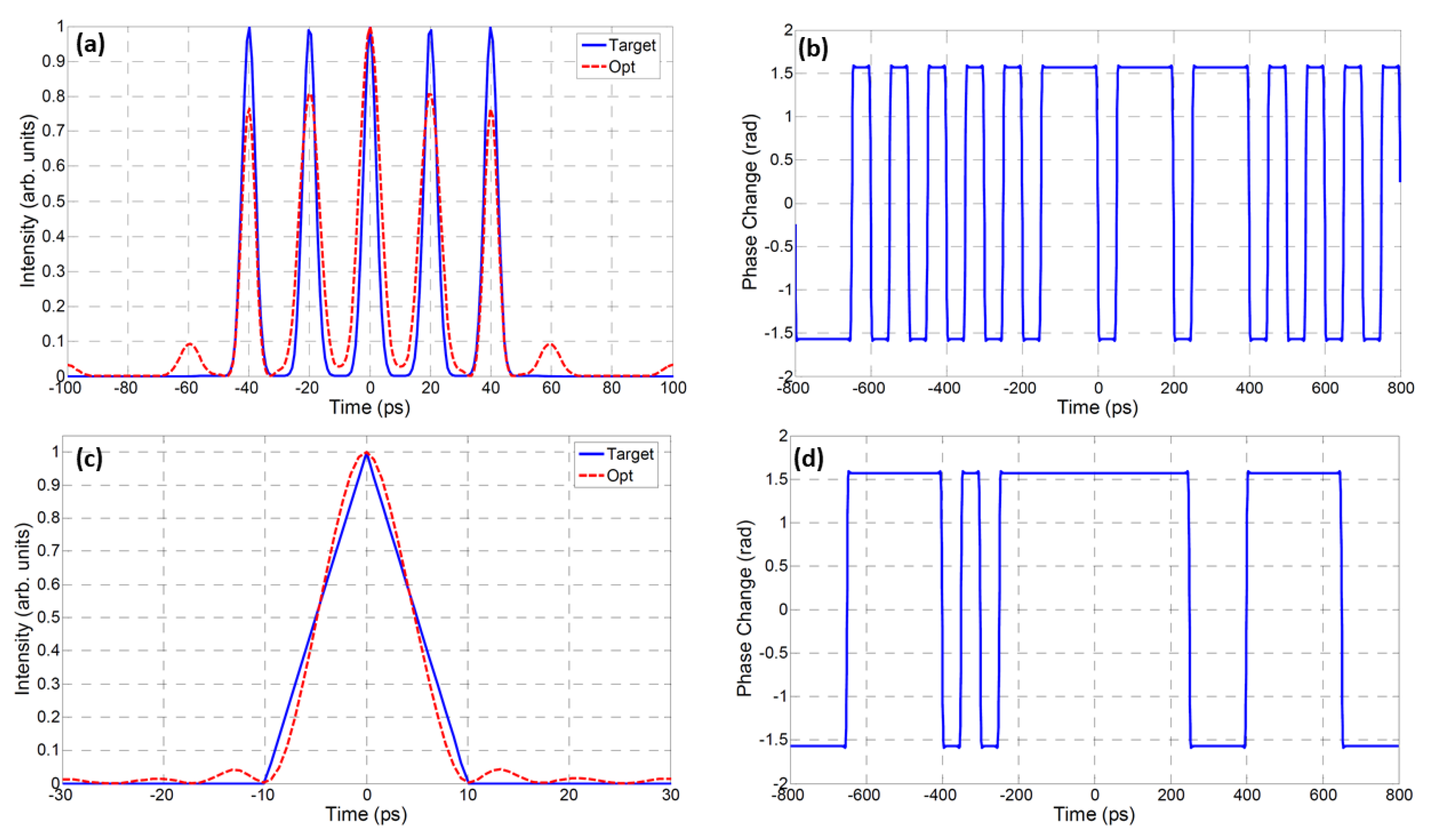
The results in Figure 5a,b, show the target and optimized mode-locked pulse intensity profiles and the corresponding optimized phase modulation, respectively. In this scenario, the target intensity profile is an ultra-high speed (50 GHz) periodic sequence of five pulses with nearly equalized amplitudes. Furthermore, the results in Figure 5c,d, show the mode-locked pulse intensity profiles and the corresponding optimized phase modulation for a 20 ps triangular pulse intensity profile. Triangular pulses have the potential of being used as gating pulses in linear frequency-resolved optical gating devices [36].
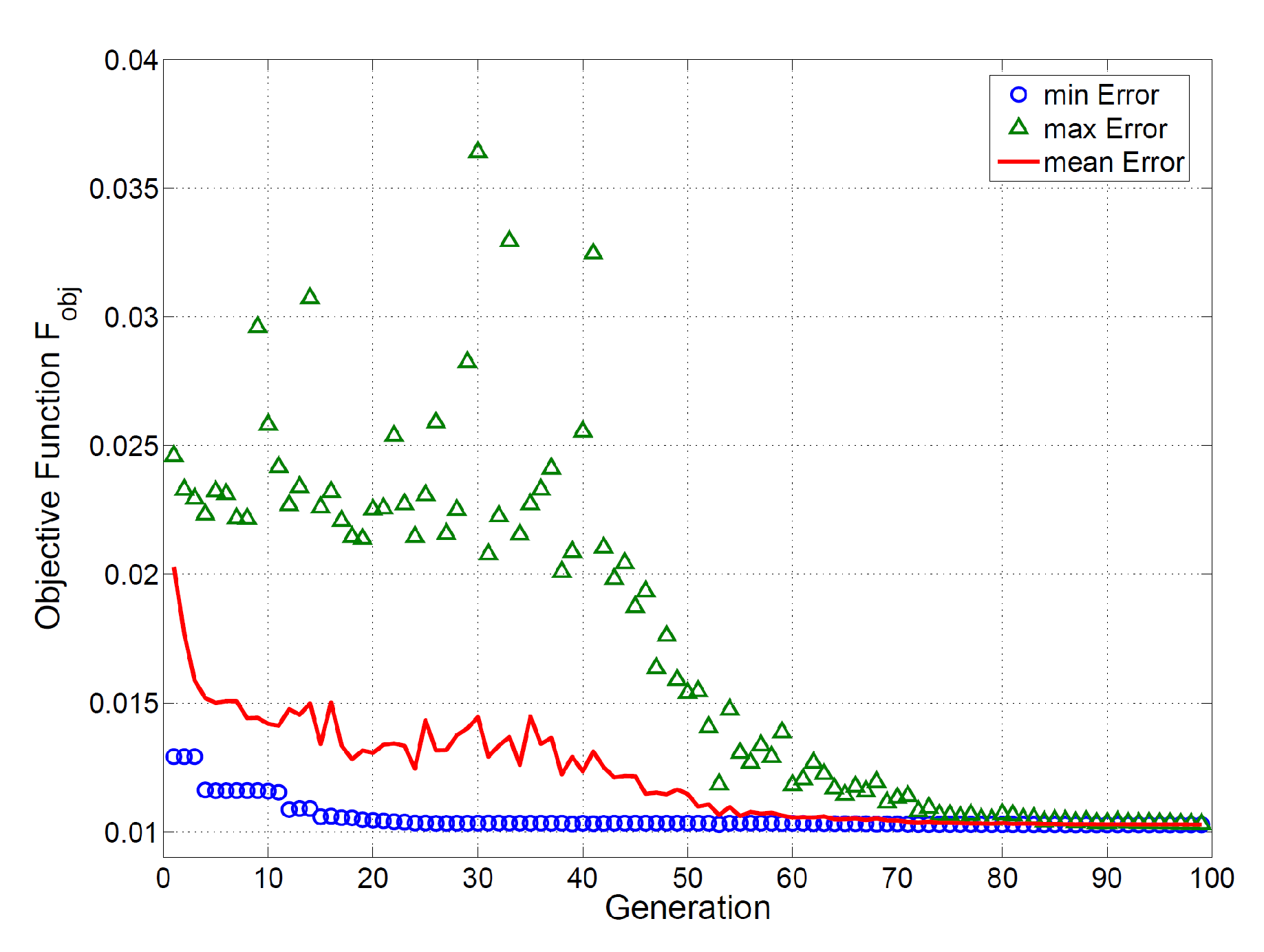
The evolution of the optimization algorithm is shown in Figure 6, with the worst, best and mean fitness values per generation. The fitness value is defined as the outcome of the objective function, which is mathematically defined as the mean of the intensity difference between the target and shaped pulse in the time domain. It is worth noting that each evaluation of the objective functions entails simulating the entire laser cavity for a minimum of 500 passes to guarantee pulse convergence. The optimization is computationally expensive, as the split-step Fourier method is employed extensively per objective function calculation. To overcome this, a Gaussian seed pulse with low intensity can be used to fasten convergence as opposed to allowing for self-starting mode-locking.

4. Conclusions

A numerical demonstration of a novel, programmable, mode-locked fiber laser is presented. A user defined 32 bit binary code word can program the laser to produce a variety of intensity profiles operating at the self-similar mode-locking regime, enabling wave-breaking free operation. The key to the laser programmability is the introduction of an all-optical-fiber-based, phase-only pulse shaper within the laser cavity. The unique programmable codes for pulse shaping were determined using a genetic algorithm for global optimization.
Although the results presented in this article are theoretical, the success of modeling experimental mode-locked fiber lasers using the CGLE further strengthens the ability of the proposed scheme to work on particles, allowing for ever increasing control over laser pulse shapes on the picosecond and femtosecond time scales. This is primarily enabled by stretching and compressing the pulse in the time domain using the two opposite ends of the same LC-FBG. As the pulse is initially stretched to the nanosecond time scale, slower BPG can impose a predefined phase modulation prior to pulse compression. Through employing the genetic algorithm for global optimization, the ability to control the pulse shape on the picosecond time scale has been numerically demonstrated. In practice, the stability of the proposed scheme depends on the consistency and accuracy of the BPG rise and fall times.

Author Contributions

Conceptualization, A.S.K.; methodology, A.S.K. and J.M.H.B.; software, A.S.K. and B.N.; validation, A.S.K. and S.A.A.; formal analysis, I.M. (Ibrahim Maharik) and B.N.; investigation, R.G. and S.A.; resources, I.M. (Issam Maaz) and A.S.K.; writing—original draft preparation, A.S.K. and R.G.; writing—review and editing, A.S.K. and I.M. (Ibrahim Maharik); supervision A.S.K. All authors have read and agreed to the published version of the manuscript.

Funding

This research received no external funding.

Conflicts of Interest

The authors declare no conflict of interest.

References

  1. Li, C.-H.; Benedick, A.J.; Fendel, P.; Glenday, A.G.; Kärtner, F.X.; Phillips, D.F.; Sasselov, D.; Szentgyorgyi, A.; Walsworth, R.L. A laser frequency comb that enables radial velocity measurements with a precision of 1 cm s-1. Nature 2008, 452, 610–612. [Google Scholar] [CrossRef] [Green Version]
  2. Hergenroder, R.; Samek, O.; Hommes, V. Femtosecond laser ablation elemental mass spectrometry. Mass Spectrom. Rev. 2006, 25, 551–572. [Google Scholar] [CrossRef] [PubMed]
  3. Schimmel, G.; Produit, T.; Mongin, D.; Kasparian, J.; Wolf, J.-P. Free space laser telecommunication through fog. Optica 2018, 5, 1338–1341. [Google Scholar] [CrossRef]
  4. Karar, A.S. Super Gaussian pulse generation in a passively mode-locked fiber laser. Optik 2019, 194, 163072. [Google Scholar] [CrossRef]
  5. Liu, W.; Fan, J.; Xie, C.; Song, Y.; Gu, C.; Chai, L.; Wang, C.; Hu, M. Programmable controlled mode-locked fiber laser using a digital micromirror device. Opt. Lett. 2017, 42, 1923–1926. [Google Scholar] [CrossRef] [PubMed]
  6. Prawiharjo, J.; Daga, N.K.; Geng, R.; Price, J.H.V.; Hanna, D.C.; Richardson, D.J.; Shepherd, D.P. High fidelity femtosecond pulses from an ultrafast fiber laser system via adaptive amplitude and phase pre-shaping. Opt. Express 2008, 16, 15074–15089. [Google Scholar] [CrossRef] [PubMed] [Green Version]
  7. Ivanenko, A.; Kobtsev, S.; Nyushkov, B.; Serebrennikov, K.; Lutsenko, D. Mode-locked fibre laser with e-controlled cavity length in ultra-wide range. Proc. SPIE Nanophotonics Micro/Nano Opt. V 2019, 11193, 111931B. [Google Scholar]
  8. Nyushkov, B.N.; Kobtsev, S.M.; Ivanenko, A.V.; Smirnov, S.V. Programmable optical waveform generation in a mode-locked gain-modulated SOA-fiber laser. Opt. Soc. Am. B 2019, 36, 3133–3138. [Google Scholar] [CrossRef]
  9. Sutter, D.H.; Steinmeyer, G.; Gallmann, L.; Matuschek, N.; Morier-Genoud, F.; Keller, U.; Scheuer, V.; Angelow, G.; Tschudi, T. Semiconductor saturable-absorber mirror assisted Kerr lens mode-locked Ti:sapphire laser producing pulses in the two-cycle regime. Opt. Lett. 1999, 24, 631–633. [Google Scholar] [CrossRef]
  10. Weiner, A.M.; Oudin, S.; Leaird, D.E.; Reitze, D.H. Shaping of femtosecond pulses using phase-only filters designed by simulated annealing. J. Opt. Soc. Am. A 1993, 10, 1112–1120. [Google Scholar] [CrossRef]
  11. Weiner, A.M. Femtosecond pulse shaping using spatial light modulators. Rev. Sci. Instrum. 2000, 71, 1929–1960. [Google Scholar] [CrossRef]
  12. Jiang, Z.; Seo, D.S.; Leaird, D.E.; Weiner, M.A. Spectral line-by-line pulse shaping. Opt. Lett. 2005, 30, 1557–1559. [Google Scholar] [CrossRef] [PubMed]
  13. Willits, J.T.; Weiner, A.M.; Cundiff, S.T. Theory of rapid-update line-byline pulse shaping. Opt. Express 2008, 16, 315–327. [Google Scholar] [CrossRef] [PubMed]
  14. Jiang, Z.; Huang, C.B.; Leaird, D.E.; Weiner, A.M. Optical arbitrary waveform processing of more than 100 spectral comb lines. Nature Photon. 2007, 1, 463–467. [Google Scholar] [CrossRef]
  15. Petropoulos, P.; Ibsen, M.; Ellis, A.; Richardson, D. Rectangular pulse generation based on pulse reshaping using a superstructured fiber Bragg grating. J. Light. Technol. 2001, 19, 746–752. [Google Scholar] [CrossRef] [Green Version]
  16. Park, Y.; Kulishov, M.; Slavk, R.; Azaña, J. Picosecond and sub-picosecond flat-top pulse generation using uniform long-period fiber gratings. Opt. Express 2006, 14, 12670–12678. [Google Scholar] [CrossRef]
  17. Karar, A.S.; Smy, T.; Steele, A.L. Nonlinear Dynamics of a Passively Mode-Locked Fiber Laser Containing a Long-Period Fiber Grating. IEEE J. Quantum Electron. 2008, 44, 254–261. [Google Scholar] [CrossRef]
  18. Slavik, R.; Oxenlowe, L.K.; Galili, M.; Mulvad, H.C.H.; Park, Y.; Azaña, J.; Jeppesen, P. Demultiplexing of 320-Gb/s OTDM data using ultrashort flat-top pulses. IEEE Photon. Technol. Lett. 2007, 19, 1855–1857. [Google Scholar] [CrossRef]
  19. Azaña, J.; Berger, N.; Levit, B.; Fischer, B. Reconfigurable generation of high repetition-rate optical pulse sequences based on time-domain phase-only filtering. Opt. Lett. 2005, 30, 3228–3230. [Google Scholar] [CrossRef]
  20. Saperstein, R.E.; Alic, N.; Panasenko, D.; Rokitski, R.; Fainman, Y. Time domain waveform processing by chromatic dispersion for temporal shaping of optical pulses. J. Opt. Soc. Am. B 2005, 22, 2427–2436. [Google Scholar] [CrossRef]
  21. Wang, X.; Wada, N. Spectral phase encoding of ultra-short optical pulse in time domain for OCDMA application. Opt. Express 2007, 15, 7319–7326. [Google Scholar] [CrossRef] [PubMed] [Green Version]
  22. Kolner, B.H. Space-time duality and the theory of temporal imaging. IEEE J. Quantum Electron. 1994, 30, 1951–1963. [Google Scholar] [CrossRef]
  23. Thomas, S.; Malacarne, A.; Poti, L.; Bogoni, A.; Azaña, J. Programmable all-fibre optical pulse shaper based on time-domain binary phase-only linear filtering. In Proceedings of the 34th European Conference on Optical Communications (ECOC), Brussels, Belgium, 21–25 September 2008. [Google Scholar]
  24. Schreiber, T.; Ortaç¸, B.; Limpert, J.; Tünnermann, A. On the study of pulse evolution in ultra-short pulse mode-locked fiber lasers by numerical simulations. Opt. Express 2007, 15, 8252–8262. [Google Scholar] [CrossRef] [PubMed]
  25. Ilday, F.Ö.; Buckley, J.R.; Clark, W.G.; Wise, F.W. Self-similar evolution of parabolic pulses in a laser. Phys. Rev. Lett. 2004, 92, 213902. [Google Scholar] [CrossRef] [Green Version]
  26. Haus, H.A. Mode-locking of lasers. IEEE J. Sel. Top. Quantum Electron. 2000, 6, 1173–1185. [Google Scholar] [CrossRef]
  27. Agrawal, G.P. Nonlinear Fiber Optics; Academic Press: New York, NY, USA, 2001. [Google Scholar]
  28. Duling, I.N., III. Subpicosecond all-fiber erbium laser. Electron. Lett. 1991, 27, 544–545. [Google Scholar] [CrossRef]
  29. Chang, Q.; Jia, E.; Suny, W. Difference schemes for solving the generalized nonlinear Schrödinger equation. J. Comp. Phys. 1999, 148, 397–415. [Google Scholar] [CrossRef]
  30. Wang, Z.; Hagerstrom, A.; Anderson, J.Q.; Tong, W.; Wu, M.; Carr, L.D.; Eykholt, R.; Kalinikos, B.A. Chaotic spin-wave solitons in magnetic film feedback rings. Phys. Rev. Lett. 2011, 107, 114102. [Google Scholar] [CrossRef] [Green Version]
  31. Hacker, M.; Stobrawa, G.; Feurer, T. Iterative Fourier transform algorithm for phase-only pulse shaping. Opt. Express 2001, 9, 191–199. [Google Scholar] [CrossRef]
  32. Rundquist, A.; Efimov, A.; Reitze, D.H. Pulse shaping with the Gerchberg-Saxton algorithm. J. Opt. Soc. Am. B 2002, 19, 2468–2478. [Google Scholar] [CrossRef]
  33. Zeidler, D.; Frey, S.; Kompa, K.-L.; Motzkus, M. Evolutionary algorithms and their application to optimal control studies. Phys. Rev. A 2001, 64, 023420. [Google Scholar] [CrossRef] [Green Version]
  34. Goldberg, D.E. Genetic Algorithm in Search, Optimization and Machine Learning; Addison-Wesley: Reading, MA, USA, 1997. [Google Scholar]
  35. Schwefel, H.P. Evolution and Optimum Seeking; Wiley: New York, NY, USA, 1995. [Google Scholar]
  36. Latkin, A.I.; Boscolo, S.; Turitsyn, S.K. Passive nonlinear pulse shaping in normally dispersive fiber. In Proceedings of the OFC/NFOEC 2008-2008 Conference on Optical Fiber Communication/National Fiber Optic Engineers Conference, San Diego, CA, USA, 24–28 February 2008. [Google Scholar]
Figure 1. Time domain pulse shaping block diagram with binary phase modulation. EO: electro-optical.
Photonics 07 00069 g001
Figure 2. Proposed mode-locked laser design with intracavity pulse shaper: (a) Basic laser cavity. (b) Phase-only pulse shaper. DCF: dispersion compensating fiber; OC: output coupler; SA: saturable absorber; EDFA: erbium doped fiber; SMF: single mode fiber; BPG: bit pattern generator; ODL: optical delay line; PM: phase modulator; LC-FBG: linearly chirped fiber Bragg grating.
Photonics 07 00069 g002
Figure 3. Intensity pulse shaping profiles generated from the proposed mode-locked laser design with the interactivity pulse shaper. (a) No pulse shaping enabled (parabolic intensity profile). (b) Pulse shaping enabled with the following 32-bit code word: 10110000000000111100000000001101. (c) Pulse shaping enabled with the following 32-bit code word: 11111001001111111111001110011111.
Photonics 07 00069 g003
Figure 4. Evolutions of parabolic intensity profiles in a mode-locked fiber laser with: (a) the interacavity pulse shaper turned off, (b) the interacavity pulse shaper turned on.
Photonics 07 00069 g004
Figure 5. Target and optimized intensity profiles with the corresponding binary phase modulation for: (a,b) a (50 GHz) periodic sequence of 5 pulses and (c,d) a 20 ps triangular pulse intensity profile.
Photonics 07 00069 g005
Figure 6. The evolution of the genetic algorithm for finding the optimized binary code word.
Photonics 07 00069 g006
Table 1. Simulation parameters for the basic laser cavity.
ParameterSymbolValue
Group velocity dispersion β 2 15.3 fs 2 /mm
Nonlinear parameter γ 0.0018 ( Wm ) 1
FWHM of reference pulse T 0 200 fs
Wavelength of operation λ 0 1550 nm
Nonlinear refractive index n 2 2.6 × 10 16 cm 2 / W
Effective cross-sectional area A eff 60 μ m 2
Dispersion length L D T 0 2 / | β 2 |
Pulse peak power P 0 λ 0 A eff / ( 2 π n 2 L D )
Fibre attenuation Γ α L D