Communication

Generation of Broadband Optical Frequency Comb Based on a Gain-Switching 1550 nm Vertical-Cavity Surface-Emitting Laser under Optical Injection

1
School of Physical Science and Technology, Southwest University, Chongqing 400715, China
2
School of Electronic and Information Engineering, Southwest University, Chongqing 400715, China
*
Author to whom correspondence should be addressed.
Photonics 2020, 7(4), 95; https://doi.org/10.3390/photonics7040095
Submission received: 24 September 2020 / Revised: 20 October 2020 / Accepted: 22 October 2020 / Published: 23 October 2020

Abstract

:
In this work, broadband optical frequency comb (OFC) generation by a gain-switching vertical-cavity surface-emitting laser (VCSEL) subject to optical injection is investigated experimentally. During implementing the experiment, a 1550 nm VCSEL under a large signal current modulation is driven into the gain-switching state with a broad noisy spectrum. By further introducing an optical injection, a high performance OFC can be produced. The experimental results demonstrate that the power and wavelength of the injection light seriously affect the performance of the produced OFC. Under proper optical injection parameters, two sub-combs originating from two orthogonal polarization components of the VCSEL can splice into a broadband total-OFC. By selecting optimized operation parameters, a high quality total-OFC can be acquired, with stable comb lines, high coherence, wide bandwidth of 70.0 GHz (56.0 GHz) within 10 dB (3 dB) amplitude variation and low single sideband phase noise at the fundamental frequency below −120.6 dBc/Hz @ 10 kHz.

Graphical Abstract

1. Introduction

Optical frequency comb (OFC) is composed of a series of equally spaced discrete comb lines, and these discrete comb lines corresponding to different frequency components can be simultaneously provided in a frequency band [1]. OFCs with good stability, high degree of coherence, as well as high repetition rates have been extensively applied in spectroscopy, metrology, optical communication, THz generation, optical arbitrary waveform generation, and other fields [1,2,3,4,5,6,7,8,9,10,11,12,13,14]. Many approaches for generating OFCs have been proposed and investigated, such as mode-locking, external modulation, and gain-switching of semiconductor lasers [15,16,17,18,19,20,21,22,23]. Mode-locked lasers can generate an OFC with broad bandwidth, but the line spacing of the OFC is difficult to tune since it is determined by the reciprocal of the round trip time for light propagating in the cavity. By using external modulation of continuous wave light, an OFC with adjustable comb line spacing can be obtained. However, in order to improve the flatness of the comb, multiple external modulators are required, which results in higher cost and insertion loss [24,25]. The approach for generating OFCs based on gain-switching semiconductor lasers has attracted much attention owe to the following advantages. On one hand, such an approach is easy to implement due to relatively simple experimental facility. On the other hand, the comb line spacing of the generated OFC is easily adjusted by varying the modulation frequency [26,27,28,29].
Compared with edge emitting semiconductor lasers, vertical cavity surface-emitting lasers (VCSELs) have some unique advantages such as low threshold current, reduced manufacturing costs, easy to integrate, high fiber coupling efficiency, etc. [30,31]. Recently, some great progresses have been made in the OFC generation based on VCSELs. Prior et al. experimentally and theoretically confirmed that a gain-switching 1550 nm VCSEL could generate a broadband total-OFC composed by two orthogonal polarization sub-combs [32,33]. To further extend the optical span of the total-OFC, the research group proposed that an optical injection is introduced into the gain-switching VCSEL, and the results showed that an OFC with enhanced optical span can be obtained by carefully adjusting the polarization of optical injection [34,35]. At present, the research on generating broadband OFC by optical injection of gain-switching VCSEL mainly focuses on the influence of the polarization direction of the injection light on the comb performance, while the dependence of comb quality on the injection parameters has not been reported in detail.
In this work, based on a gain-switching 1550 nm VCSEL under optical injection, we investigate experimentally the generation of broadband OFC, and the influences of injection power and injection light wavelength on the bandwidth, the number of comb lines, and signal to noise ratio (SNR) are focused on. A broadband OFC with 70.0 GHz (56.0 GHz) bandwidth within 10 dB (3 dB) power variation can be obtained through selecting appropriate injection parameters.

2. Experimental Setup

Figure 1 shows the experimental setup for generating optical frequency comb (OFC). A commercial 1550 nm VCSEL (Raycan) is used in this experiment, and its current and temperature are controlled by a high accuracy and low noise current-temperature controller (ILX-Lightwave, LDC-3724C). A continuous light output from a tunable laser (TL, Santec TSL-710) is injected into the VCSEL after passing through a variable attenuator (VA1), a polarization controller (PC1), a 20/80 fiber coupler (FC1), an optical circulator (OC) successively. The injection power Pi can be adjusted by controlling VA1 and be monitored by an optical power meter (PM). PC1 is employed to control the polarization of the injection light. A microwave frequency synthesizer (MFS, Agilent E8257C) is used to generate a sinusoidal radio frequency (RF) signal. The output of the VCSEL passes through OC, an erbium doped fiber amplifier (EDFA), and then is divided into two parts by another 50/50 fiber coupler (FC2). A half of the FC2 output is employed to measure X-polarized OFC (named as X-OFC) and Y-polarized OFC (named as Y-OFC) via PC2 and a polarization beam splitter (PBS), and the other half is used to observe the total-OFC composed by X-OFC and Y-OFC. In the measurement system, an optical spectrum analyzer (OSA, Aragon Photonics BOSA lite +, 20 MHz resolution) is adopted to measure optical spectrum. Power spectrum and single sideband (SSB) phase noise are recorded by an electrical spectrum analyzer (ESA, R&S FSW, 67 GHz bandwidth) after being converted into an electric signal by a photodetector (PD1, U2T-XPDV2150R, 50 GHz bandwidth), and the time series is monitored by a digital oscilloscope (OSC, Agilent X91604A, 16 GHz bandwidth) after being converted into an electric signal by another photodetector (PD2, New Focus 1544B, 12 GHz bandwidth). Considering that the used ESA and OSC possess different bandwidths, two PDs with different bandwidths are adopted for ESA and OSC, respectively. During the experiment, the temperature of the 1550 nm VCSEL is stabilized at 20.47 °C.

3. Results and Discussion

First, we characterize the basic properties of the 1550 nm VCSEL used in this work under free-running. To obtain polarization-resolved power-current (P-I) curve, we inspect the spectrum output from one port of the PBS during adjusting PC2. Normally, there are two peaks can be observed in the spectrum. One peak locating at shorter wavelength corresponds to Y polarization component (Y-PC), and the other peak locating at longer wavelength corresponds to X polarization component (X-PC). For PC2 is set at a specific direction, the power of X-PC achieves its minimum. Under this condition, the output from the port of the PBS is the Y-PC. Correspondingly, the output from the other port of the PBS is the X-PC. Figure 2a measures the polarization-resolved P-I curve. As presented in this diagram, the threshold current Ith of the VCSEL is about 1.6 mA. For IthI < 8.0 mA, Y-PC is always lasing whereas X-PC is suppressed, where the Y-PC and X-PC are characterized by the solid line and dashed line, respectively. Figure 2b records the corresponding optical spectrum of the VCSEL biased at 5.0 mA (about 3.13 Ith). It can be observed that the dominant Y-PC oscillates at 1551.97 nm and the suppressed X-PC is located at 1552.23 nm, and the wavelength (frequency) interval between the two polarization components is approximate 0.26 nm (32.38 GHz). By measuring the noise spectral distribution, the relaxation oscillation frequency (Fr) of the VCSEL can be obtained [36,37]. Figure 2c shows the variation of Fr of the VCSEL with the bias current. Obviously, the relaxation oscillation frequency exhibits a nonlinear varied trend with the increase of bias current, which is similar with that reported in Reference [38]. In the following experiments, the bias current is fixed at 5.0 mA. Under this condition, the free-running 1550 nm VCSEL has a relaxation oscillation frequency of about 2.63 GHz.
Next, we will investigate the output characteristics of the VCSEL under only current modulation. Figure 3 displays the time series, optical spectra, and power spectra of the laser under current modulation with modulation frequency fm = 2.8 GHz and modulation power Pm = −5.0 dBm (a), 7.0 dBm (b), 13.0 dBm (c), and 17.0 dBm (d), respectively. For Pm = −5.0 dBm (Figure 3(a1–a3)), an approximate sinusoid time series with a period of T (=1/ fm) is observed, and the corresponding optical spectrum includes a few comb lines since the laser is not driven into a gain-switching state due to relatively weak modulation power. However, the optical spectrum possesses a high signal to noise ratio (SNR, about 65 dB). SNR, defined as the difference between the maximum power level of the output optical spectrum and the noise pedestal, is an important index to characterize the OFC quality. As shown in Figure 3(a3), the strongest peak of the power spectrum locates at 2.8 GHz, which is equal to the modulation frequency fm. For Pm = 7.0 dBm (Figure 3(b1–b3)), the time series presents a regular pulse train with a period of 357.1 ps, which is equal to the reciprocal of modulation frequency fm (= 2.8 GHz), and the optical spectrum is broadened and contains much more comb lines (Figure 3(b2)). As a result, the laser is driven into a gain-switching with regular pulse state. Correspondingly, much more higher-order harmonics can be observed in the power spectrum. For Pm = 13.0 dBm (Figure 3(c1–c3)), the periodic waveform with two peak intensities can be clearly observed in the time series, more comb lines with a frequency interval of fm/2 emerge in the optical spectrum, and suharmonic components are observed in the power spectrum. All these features indicate that the VCSEL operates at a period-2 state [39], which means that the period of the output pulse doubles. When Pm is increased to 17.0 dBm (Figure 3(d1–d3)), the time series shows random intensity pulsing. The optical spectrum presents elevated and broadened noise spectrum without discernible comb lines. In the power spectrum, although the discrete harmonics remain clearly discernible, the level of continuous noise is significantly stronger than the noise floor. Under this case, the relatively strong spontaneous emission noise makes the frequency chirping noisier, and then the comb lines in optical spectrum are lost. Meanwhile, optical pulses switch-off to a level at which the spontaneous emission noise dominates the evolution [40]. The similar state has also been observed in a gain-switching of discrete mode lasers or distributed feedback lasers [22,26]. The width of noise spectrum of gain-switching 1550 nm VCSEL is related to the frequency interval between the two polarization components of the free-running VCSEL [35]. Additionally, through comparing Figure 2b and Figure 3, one can see that the optical spectrum exists in a red-shift after adopting current modulation due to the heating effect resulted by the current modulation. Above results show that it is difficult to generate an OFC with broad bandwidth based on a 1550 nm VCSEL under only current modulation. However, after further introducing optical injection into the gain-switching VCSEL operating at the state shown in Figure 3d, it is possible to generate a high quality OFC. In the following investigations, we fix fm at 2.8 GHz and Pm at 17.0 dBm.
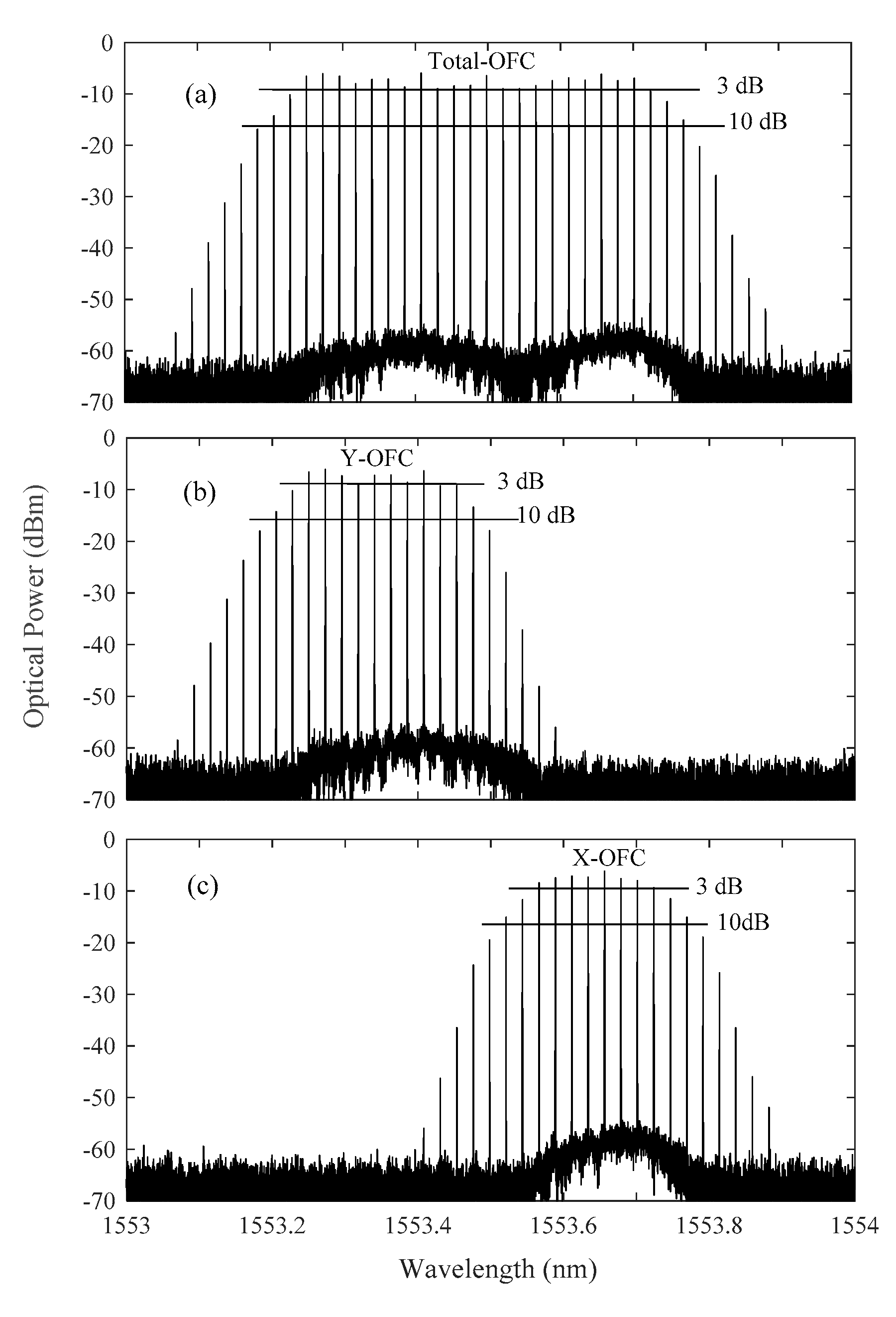
Then, an external optical injection is further introduced into the VCSEL to obtain high quality OFC. As reported in References [34,35], the performance of the OFC generated in VCSELs under optical injection are dependent on the polarization of the injection light. Our experimental results show that for the current modulated 1550 nm VCSEL operating at the state shown in Figure 3d, the optimized polarization of the injection light is in the intermediate between Y-PC and X-PC. Therefore, in the whole experiment, the polarization direction of the injection light is fixed at the intermediate between Y-PC and X-PC. Figure 4 gives the optical spectra of total-OFC, Y-OFC, and X-OFC output from the gain-switching VCSEL under optical injection with injection light wavelength λi = 1553.4843 nm and injection power Pi = 266.80 μW. As shown in Figure 4a, the total-OFC displays a flat and broadband spectrum structure, and the envelope of the optical spectrum is similar with that of the optical spectrum obtained under only current modulation (as shown in Figure 3(d2)). The bandwidth of the total-OFC is about 70.0 GHz (56.0 GHz) within 10 dB (3 dB) amplitude variation corresponding to 26 (21) comb lines. Here, the OFC bandwidth is defined as the continuous frequency range within which the difference among the powers of comb lines is less than 10 dB (3 dB). Via PBS, the optical spectrum distributions of two sub-combs named as Y-OFC and X-OFC can be measured as shown in Figure 4b,c, respectively. As shown in Figure 4b, Y-OFC locates at short wavelength region since it is devoted by Y-PC, and the 10 dB bandwidth is about 33.6 GHz (13 comb lines). The X-OFC (as shown in Figure 4c) originating from X-PC, locates at long wavelength region, and the 10 dB bandwidth is about 30.8 GHz (12 comb lines). As a result, almost same number of comb lines is getting for X-OFC and Y-OFC. The reason for that is as follows: the X-PC and Y-PC possess comparable power under strong current modulation (as shown in Figure 3(d2)), and meanwhile the optical powers injected into X-PC and Y-PC are identical since both the polarization and the wavelength of the injection light are nearly in the intermediate between Y-PC and X-PC. From the three diagrams, it can be seen that the total-OFC originating from splicing two sub-combs, possesses better performance. As a result, we will only analyze the performance of the total-OFC in the following.
Besides wide bandwidth and good amplitude flatness, a high quality OFC should also possess high spectral coherence. To evaluate the coherence of the generated total-OFC, the detailed power spectrum and SSB phase noise of total-OFC is measured with an ESA, where the SSB phase noise is obtained via a toolbox of “Phase Noise” in the ESA. Here, the electrical beat tone signal locating at fm (=2.8 GHz) is chosen for a representative. As shown in Figure 5a, SNR is about 66 dB, and the 3 dB linewidth is less than 1 Hz limited by the minimum resolution of the ESA. Figure 5b presents the measured SSB phase noise, and the phase noise is about −120.6 dBc/Hz at 10 kHz offset frequency, which means that the comb lines are stable and highly coherent. Actually, high mutual coherence can also be observed between two lines belong to different polarization sub-combs due to the fact that two polarization modes in a VCSEL are anti-correlated [32].
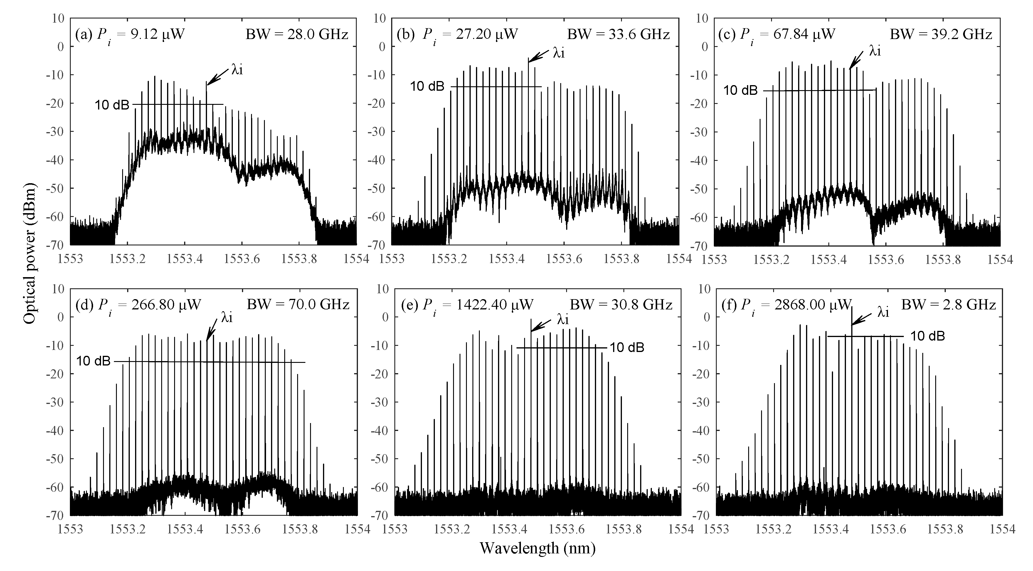
Above experimental results have demonstrated that a high quality OFC can be generated by a gain-switching VCSEL subject to optical injection with given λi = 1553.4843 nm and Pi = 266.80 μW. In the following, we will investigate the performance of total-OFC under different Pi values. Figure 6 shows the optical spectra output from the gain-switching VCSEL under optical injection with a fixed injection light wavelength λi = 1553.4843 nm and different injection power Pi. For Pi = 9.12 μW (Figure 6a), some comb lines with uneven amplitude and small SNR appear in the optical spectrum, and the total-OFC bandwidth is about 28.0 GHz corresponding to 11 comb lines. For Pi = 27.20 μW (Figure 6b) and 67.84 μW (Figure 6c), a relatively strong optical injection significantly suppresses the noise level and enhances SNR of the comb lines, and the total-OFC has a bandwidth about 33.6 GHz (13 comb lines) for Figure 6b and 39.2 GHz (15 comb lines) for Figure 6c, respectively. When Pi is increased to 266.80 μW (Figure 6d), the noise pedestal is further decreased, and the proper optical injection equalizes the power of X-OFC and Y-OFC. Under this case, as shown in Figure 6d, a flat total-OFC with 70.0 GHz bandwidth (26 comb lines) is generated. Further increasing Pi to 1422.40 μW (Figure 6e), a strong injection power is beneficial for suppressing noise, but it also degrades the flatness of total-OFC. As a result, the bandwidth decreases to 30.8 GHz (12 comb lines). In particular, for a too strong optical injection of Pi = 2868.00 μW, there are only two comb lines included into the 10 dB bandwidth, and the bandwidth decreases to 2.8 GHz.
Figure 7 shows the bandwidth variation of total-OFC with the injection power Pi under λi = 1553.4843 nm. As shown in this diagram, with the increase of injection power Pi, the bandwidth of OFC firstly increases very sharply to a level about 70 GHz, after maintaining the level witnin a range of injection power, and finally experiences a downward trend. For 101.72 μW ≤ Pi 1284.80 μW, the bandwidths of the total-OFCs are beyond 60.0 GHz. Therefore, for a given λi = 1553.4843 nm, a broadband OFC can be generated under 101.72 μW ≤ Pi 1284.80 μW.
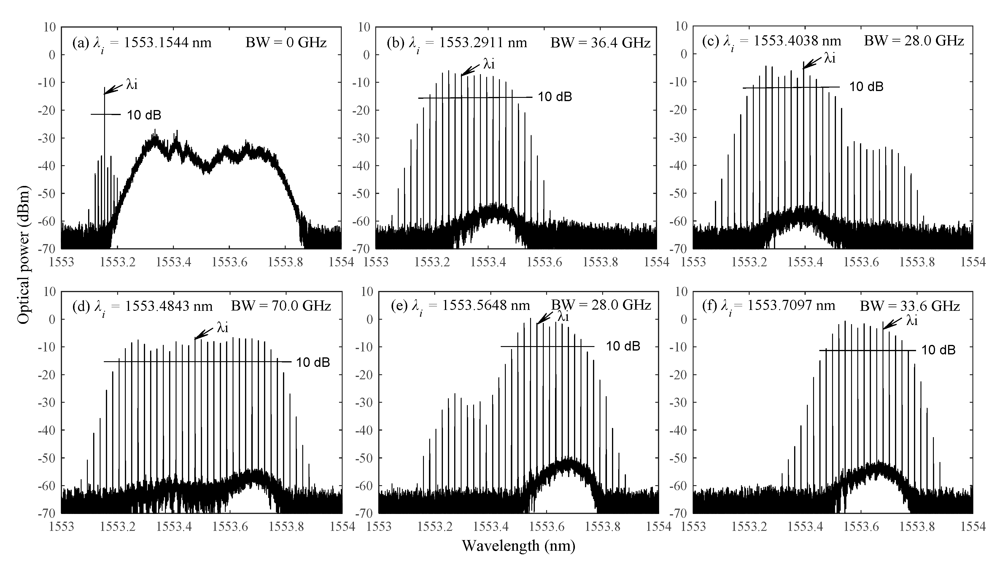
Finally, we will analyze the influence of different injection light wavelength on the performance of the total-OFC. Figure 8 displays the optical spectra output from the gain-switching VCSEL under optical injection with Pi = 266.80 μW and different λi. For λi = 1553.1544 nm (Figure 8a), the injection light wavelength is outside the noise pedestal of gain-switching VCSEL. Under this circumstance, the optical spectrum is composed of the optical spectrum without optical injection (Figure 3d) and the regenerated injection light together with its modulated sideband. For λi = 1553.2911 nm (Figure 8b), the injection light wavelength is gradually near to the Y-PC of the 1550 nm VCSEL. Under this condition, the noise pedestal is suppressed obviously, and meanwhile the Y-PC is motivated to generate Y-OFC with 36.4 GHz bandwidth (including 14 comb lines). For λi = 1553.4038 nm (Figure 8c), X-OFC is also stimulated while Y-OFC is still the primary component of the total-OFC, the total-OFC bandwidth is about 28.0 GHz (11comb lines). For λi = 1553.4843 nm (Figure 8d), the injection light wavelength is almost in the middle of X-PC and Y-PC. Under this case, the intensity of X-OFC is similar with that of Y-OFC, and then a broadband total-OFC with a bandwidth of about 70.0 GHz (26 comb lines) can be generated. For λi = 1553.5648 nm (Figure 8e), the injection light wavelength is slightly nearer to the X-PC component, which results in the increase of the power of X-OFC and the decrease of the power of Y-OFC. The total-OFC has a 28.0 GHz bandwidth (11comb lines). For λi is increased to 1553.7097 nm (Figure 8f), the injection light wavelength is far away from the Y-PC, and therefore only the X-OFC is motivated. The bandwidth of the total-OFC is about 33.6 GHz (13 comb lines).
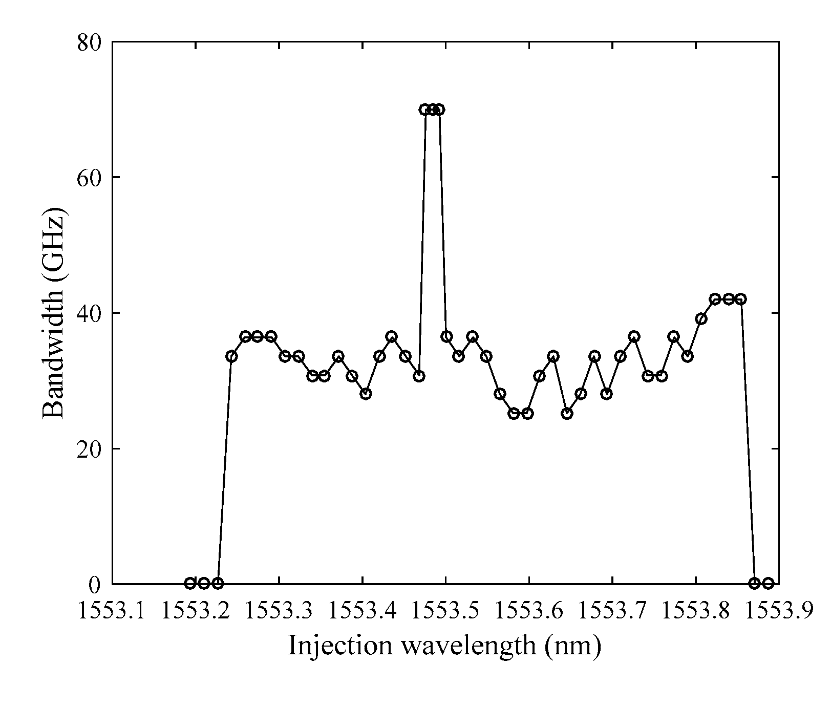
Figure 9 shows the variation trend of the total-OFC bandwidth with the injection light wavelength under Pi = 266.80 μW. Here, the frequency step of the injection light is set as 2 GHz. For λi < 1553.2428 nm or λi > 1553.8547 nm, the injection light is outside the noise pedestal as shown in Figure 8a. Under this case, the gain-switching VCSEL cannot be locked to generate OFC. For 1553.2428 nm ≤ λi ≤ 1553.4683 nm, compared with X-PC the injection light wavelength is nearer to Y-PC, Y-OFC is stimulated and dominant while the X-OFC is suppressed or subsidiary. The OFC bandwidth fluctuates between 28.0 GHz and 36.4 GHz. For 1553.4683 nm < λi < 1553.5004 nm, Y-OFC and X-OFC have almost similar power, and two sub-combs link up to form a total-OFC with broad bandwidth about 70.0 GHz. For 1553.5004 nm ≤ λi ≤ 1553.8547 nm, the injection light wavelength is nearer to X-PC. As a result, the X-OFC is dominant while the Y-OFC is subsidiary or suppressive, and the bandwidth of total-OFC is within the range of 28.0 GHz–42.0 GHz. Additionally, it should be pointed out that although the results in Figure 9 are obtained under 2 GHz frequency step of the injection light, the same variation trend can be obtained for a finer frequency step.

4. Conclusions

In summary, we experimentally investigated the broadband OFC generation based on a gain-switching VCSEL subject to optical injection, and the performance of the generated OFC are analyzed. Firstly, a large modulated current with modulation frequency fm = 2.8 GHz and modulation power Pm = 17.0 dBm is adopted to drive a 1550 nm VCSEL into the gain-switching state with a broad noisy spectrum. Next, an injection light is further introduced for generating high quality OFC. The experimental results show that for a given injection light wavelength λi = 1553.4843 nm, the bandwidth of total-OFC (constituted by X-OFC and Y-OFC) firstly increases very sharply, then maintains at a relatively high level, and finally experiences a downward trend with the increase of injection power Pi. For a given injection power Pi = 266.80 μW, when λi is closer to Y-PC of the 1550 nm VCSEL, the Y-OFC is the major contributor to the total-OFC. On the contrary, when λi is closer to X-PC of the 1550 nm VCSEL, the X-OFC becomes the major contributor to the total-OFC. In particularly, if λi is set at the middle of two polarization modes, X-OFC and Y-OFC are almost equalized. As a result, the bandwidth of the generated OFC is enhanced obviously. Under optimized operation parameters, we experimentally acquire a total-OFC with a bandwidth of 70.0 GHz (56.0 GHz) within 10 dB (3 dB) amplitude variation, whose single sideband phase noise at the fundamental frequency is below −120.6 dBc/Hz @ 10 kHz.

Author Contributions

H.R. was responsible for performing the experiment, analyzing the results, and writing of the paper. L.F. was responsible for performing part of the experiment and revising the manuscript. N.L. was responsible for recording experimental data. Z.W. and G.X. were responsible for the discussion of the results and reviewing/editing/proof-reading of the manuscript. All authors have read and agreed to the published version of the manuscript.

Funding

This work was supported in part by the National Natural Science Foundation of China under Grant 61775184 and Grant 61875167, and in part by the Fundamental Research Funds for the Central Universities of China under Grant SWU120017.

Conflicts of Interest

The authors declare no conflict of interest.

References

  1. Newbury, N.R. Searching for applications with a fine-tooth comb. Nat. Photon. 2011, 5, 186–188. [Google Scholar] [CrossRef]
  2. Diddams, S.; Vahala, K.; Udem, T. Optical frequency combs: Coherently uniting the electromagnetic spectrum. Science 2020, 369, 267–278. [Google Scholar]
  3. Yan, X.L.; Zou, X.H.; Pan, W.; Yan, L.S.; Azaña, J. Fully digital programmable optical frequency comb generation and application. Opt. Lett. 2018, 43, 283–286. [Google Scholar] [CrossRef] [PubMed]
  4. Cundiff, S.T.; Weiner, A.M.; Andrew, M. Optical arbitrary waveform generation. Nat. Photon. 2010, 4, 760–766. [Google Scholar] [CrossRef]
  5. Li, P.L.; Ma, X.L.; Shi, W.H.; Xu, E.M. Optical arbitrary waveform generation based on multi-wavelength semiconductor fiber ring laser. Opt. Laser Technol. 2017, 94, 228–233. [Google Scholar] [CrossRef]
  6. Zhou, X.; Zheng, X.P.; Wen, H.; Zhang, H.Y.; Guo, Y.L.; Zhou, B.K. All optical arbitrary waveform generation by optical frequency comb based on cascading intensity modulation. Opt. Commun. 2011, 284, 3706–3710. [Google Scholar] [CrossRef]
  7. Cingöz, A.; Yost, D.C.; Allison, T.K.; Ruehl, A.; Fermann, M.E.; Hartl, I.; Ye, J. Direct frequency comb spectroscopy in the extreme ultraviolet. Nature 2012, 482, 68–71. [Google Scholar] [CrossRef] [PubMed] [Green Version]
  8. Sadiek, I.; Mikkonen, T.; Vainio, M.; Toivonen, J.; Foltynowicz, A. Optical frequency comb photoacoustic spectroscopy. Phys. Chem. Chem. Phys. 2018, 20, 27849–27855. [Google Scholar] [CrossRef] [PubMed] [Green Version]
  9. He, J.; Long, F.T.; Deng, R.; Shi, J.; Dai, M.; Chen, L. Flexible multiband OFDM ultra-wideband services based on optical frequency combs. J. Opt. Commun. Netw. 2017, 9, 393–400. [Google Scholar] [CrossRef]
  10. Song, G.B.; Wang, T.S.; Dong, F.; Zhang, Y. Transmission characteristics of 24.5 Gb/s atmospheric laser communication based on optical frequency comb. Opt. Commun. 2020, 465, 125602. [Google Scholar] [CrossRef]
  11. Tan, J.; Zhao, Z.P.; Wang, Y.H.; Zhang, Z.K.; Liu, J.G.; Zhu, N.H. 12.5 Gb/s multi-channel broadcasting transmission for free-space optical communication based on the optical frequency comb module. Opt. Express 2018, 26, 2099–2106. [Google Scholar] [CrossRef] [PubMed]
  12. Hasanuzzaman, G.K.M.; Shams, H.; Renaud, C.C.; Mitchell, J.; Seeds, A.J.; Iezekiel, S. Tunable THz signal generation and radioover-fiber link based on an optoelectronic oscillator-driven optical frequency comb. J. Lightwave Technol. 2019, 38, 5240–5247. [Google Scholar] [CrossRef]
  13. Ponnampalam, L.; Fice, M.; Shams, H.; Renaud, C.; Seeds, A. Optical comb for generation of a continuously tunable coherent THz signal from 122.5 GHz to >2.7 THz. Opt. Lett. 2018, 43, 2507–2510. [Google Scholar] [CrossRef] [PubMed]
  14. Yu, J.G.; Li, K.L.; Chen, Y.X.; Zhao, L.; Huang, Y.T.; Li, Y.T.; Ma, J.; Shan, F.L. Terahertz-wave generation based on optical frequency comb and single mach-zehnder modulator. IEEE Photon. J. 2020, 12, 7900808. [Google Scholar] [CrossRef]
  15. Davila-Rodriguez, J.; Bagnell, K.; Delfyett, P.J. Frequency stability of a 10 GHz optical frequency comb from a semiconductor-based mode-locked laser with an intracavity 10,000 finesse etalon. Opt. Lett. 2013, 38, 3665–3668. [Google Scholar] [CrossRef]
  16. Parker, J.S.; Bhardwaj, A.; Binetti, P.R.A.; Yung-Jr, H.; Coldren, L.A. Monolithically integrated gain-flattened ring mode-locked laser for comb-line generation. IEEE Photon. Technol. Lett. 2012, 24, 131–133. [Google Scholar] [CrossRef]
  17. He, C.; Pan, S.L.; Guo, R.H.; Zhao, Y.J.; Pan, M.H. Ultraflat optical frequency comb generated based on cascaded polarization modulators. Opt. Lett. 2012, 37, 3834–3836. [Google Scholar] [CrossRef]
  18. Li, X.Y.; Xiao, J.N. Flattened optical frequency-locked multi-carrier generation by cascading one EML and one phase modulator driven by different RF clocks. Opt. Fiber Technol. 2015, 23, 116–121. [Google Scholar] [CrossRef]
  19. Li, D.; Wu, S.B.; Liu, Y.; Guo, Y.F. Flat optical frequency comb generation based on a dual-parallel Mach–Zehnder modulator and a single recirculation frequency shift loop. Appl. Opt. 2020, 59, 1916–1923. [Google Scholar] [CrossRef]
  20. Qu, K.; Zhao, S.H.; Li, X.; Tan, Q.G.; Zhu, Z.H. Ultraflat and broadband optical frequency comb generator based on cascaded two dual-electrode Mach–Zehnder modulators. Opt. Rev. 2018, 25, 264–270. [Google Scholar] [CrossRef]
  21. Wang, Z.F.; Ma, M.; Sun, H.; Khalil, M.; Adams, R.; Yim, K.; Jin, X.; Chen, L.R. Optical frequency comb generation using CMOS compatible cascaded Mach–Zehnder modulators. IEEE J. Quantum Electron. 2019, 55, 8400206. [Google Scholar] [CrossRef]
  22. Anandarajah, P.M.; Maher, R.; Xu, Y.Q.; Latkowski, S.; O’Carroll, J.; Murdoch, S.G.; Phelan, R.; O’Gorman, J.; Barry, L.P. Generation of coherent multicarrier signals by gain switching of discrete mode lasers. IEEE Photon. J. 2011, 3, 112–122. [Google Scholar] [CrossRef]
  23. Zhou, R.; Latkowski, S.; O’Carroll, J.; Phelan, R.; Barry, L.P.; Anandarajah, P. 40 nm wavelength tunable gain-switched optical comb source. Opt. Express 2011, 19, 415–420. [Google Scholar] [CrossRef] [PubMed]
  24. Gheorma, I.L.; Gopalakrishnan, G.K. Flat frequency comb generation with an integrated dual-parallel modulator. IEEE Photon. Technol. Lett. 2007, 19, 1011–1013. [Google Scholar] [CrossRef]
  25. Wu, R.; Supradeepa, V.R.; Long, C.M.; Leaird, D.E.; Weiner, A.M. Generation of very flat optical frequency combs from continuous-wave lasers using cascaded intensity and phase modulators driven by tailored radio frequency waveforms. Opt. Lett. 2010, 35, 3234–3236. [Google Scholar] [CrossRef]
  26. Rosado, A.; Pérez-Serrano, A.; Tijero, J.M.G.; Valle, Á.; Pesquera, L.; Esquivias, I. Experimental study of optical frequency comb generation in gain-switched semiconductor lasers. Opt. Laser Technol. 2018, 108, 542–550. [Google Scholar] [CrossRef]
  27. Pascual, M.D.G.; Zhou, R.; Smyth, F.; Anandarajah, P.M.; Barry, L.P. Software reconfigurable highly flexible gain switched optical frequency comb source. Opt. Express 2015, 23, 23225–23235. [Google Scholar] [CrossRef]
  28. Zhu, H.T.; Wang, R.; Pu, T.; Xiang, P.; Zheng, J.L.; Fang, T. A novel approach for generating flat optical frequency comb based on externally injected gain-switching distributed feedback semiconductor laser. Laser Phys. Lett. 2016, 14, 026201. [Google Scholar] [CrossRef]
  29. Anandarajah, P.M.; Duill, S.P.O.; Zhou, R.; Barry, L.P. Enhanced optical comb generation by gain-switching a single-mode semiconductor laser close to its relaxation oscillation frequency. IEEE J. Sel. Top. Quantum Electron. 2015, 21, 592–600. [Google Scholar] [CrossRef]
  30. Koyama, F. Recent advances of VCSEL photonics. J. Lightwave Technol. 2006, 24, 4502–4513. [Google Scholar] [CrossRef]
  31. Jewell, J.L.; Harbison, J.P.; Scherer, A.; Lee, Y.H.; Florez, L.T. Vertical-cavity surface-emitting lasers: Design, growth, fabrication, characterization. IEEE J. Quantum Electron. 1991, 27, 1332–1346. [Google Scholar] [CrossRef] [Green Version]
  32. Prior, E.; De Dios, C.; Ortsiefer, M.; Meissner, P.; Acedo, P. Understanding VCSEL-based gain switching optical frequency combs: Experimental study of polarization dynamics. J. Lightwave Technol. 2015, 33, 4572–4579. [Google Scholar] [CrossRef]
  33. Quirce, A.; De Dios, C.; Valle, A.; Pesquera, L.; Acedo, P. Polarization dynamics in VCSEL-based gain switching optical frequency combs. J. Lightwave Technol. 2018, 36, 1798–1806. [Google Scholar] [CrossRef]
  34. Prior, E.; De Dios, C.; Criado, R.; Ortsiefer, M.; Meissner, P.; Acedo, P. Dynamics of dual-polarization VCSEL-based optical frequency combs under optical injection locking. Opt. Lett. 2016, 41, 4083–4086. [Google Scholar] [CrossRef] [PubMed]
  35. Quirce, A.; De Dios, C.; Valle, A.; Acedo, P. VCSEL-based optical frequency combs expansion induced by polarized optical injection. IEEE J. Sel. Top. Quantum Electron. 2019, 25, 1500109. [Google Scholar] [CrossRef]
  36. Ma, L.H.; Xia, G.Q.; Chen, J.J.; Wu, Z.M. Temperature dependence of characteristic parameters of 1550 nm vertical-cavity surface-emitting laser. Acta Phys. Sin. 2018, 67, 214204. [Google Scholar]
  37. Perez, P.; Valle, A.; Noriega, I.; Pesquera, L. Measurement of the intrinsic parameters of single-mode VCSELs. J. Lightwave Technol. 2014, 32, 1601–1607. [Google Scholar] [CrossRef] [Green Version]
  38. Chen, J.J.; Wu, Z.M.; Deng, T.; Tang, X.; Yang, X.; Xia, G.Q. Current- and feedback-induced state bistability in a 1550 nm-VCSEL with negative optoelectronic feedback. IEEE Photon. J. 2017, 9, 1500310. [Google Scholar] [CrossRef]
  39. Deng, T.; Xia, G.Q.; Chen, J.J.; Tang, X.; Lin, X.D.; Yang, X.; Huang, S.W.; Wu, Z.M. Experimental investigation on nonlinear dynamics of 1550 nm VCSEL simultaneously subject to orthogonal optical injection and negative optoelectronic feedback. Laser Phys. 2017, 27, 045402. [Google Scholar] [CrossRef]
  40. Rosado, A.; Pérez, A.; Tijero, J.M.G.; Gutierrez, A.V.; Pesquera, L.; Esquivias, I. Numerical and experimental analysis of optical frequency comb generation in gain-switched semiconductor lasers. IEEE J. Quantum Electron. 2019, 55, 2001012. [Google Scholar] [CrossRef]
Figure 1. Schematic of the experimental setup. TL: tunable laser; VCSEL: vertical-cavity surface-emitting laser; VA: variable attenuator; PC: polarization controller; FC: fiber coupler; PM: power meter; OC: optical circulator; MFS: microwave frequency synthesizer; DC: direct current; EDFA: erbium doped fiber amplifier; PBS: polarization beam splitter; OSA: optical spectrum analyzer; PD: photodiode; ESA: electrical spectrum analyzer; DSO: digital storage oscilloscope.
Photonics 07 00095 g001
Figure 2. Experimentally measured (a) polarization-resolved P-I curve, (b) optical spectrum of the free-running 1550 nm VCSEL biased at 5.0 mA, (c) Fr-I curve.
Photonics 07 00095 g002
Figure 3. Time series (first column), optical spectra (second column), and power spectra (third column) of a current modulated 1550 nm VCSEL at I = 5.0 mA and fm = 2.8 GHz under different values of Pm, where (a) Pm = −5.0 dBm, (b) Pm = 7.0 dBm, (c) Pm = 13.0 dBm, and (d) Pm = 17.0 dBm. The gray curves in the power spectra denote the noise floor.
Photonics 07 00095 g003
Figure 4. Experimentally measured (a) total-OFC, (b) Y-OFC, (c) X-OFC output from a gain-switching VCSEL under optical injection with injection light wavelength λi = 1553.4843 nm and injection power Pi = 266.80 μW.
Photonics 07 00095 g004
Figure 5. Experimentally measured (a) detailed power spectrum and (b) SSB phase noise centered at 2.8 GHz under a resolution bandwidth of 1 Hz.
Photonics 07 00095 g005
Figure 6. Experimentally measured total-OFC output from a gain-switching VCSEL under optical injection with λi = 1553.4843 nm and different values of Pi, where (a) Pi = 9.12 μW, (b) Pi = 27.20 μW, (c) Pi = 67.84 μW, (d) Pi =266.80 μW, (e) Pi = 1422.40 μW, and (f) Pi =2868.00 μW.
Photonics 07 00095 g006
Figure 7. Evolution of the total-OFC bandwidth as a function of the injection power Pi under λi = 1553.4843 nm.
Photonics 07 00095 g007
Figure 8. Experimentally measured total-OFC output from the gain-switching VCSEL under optical injection with fixed Pi = 266.80 μW and different values of λi, where (a) λi = 1553.1544 nm, (b) λi = 1553.2911 nm, (c) 1553.4038 nm, (d) λi = 1553.4843 nm, (e) λi = 1553.5648 nm, and (f) λi =1553.7097 nm.
Photonics 07 00095 g008
Figure 9. Evolution of the total-OFC bandwidth as a function of the injection light wavelength for the gain-switching VCSEL at injection power Pi = 266.80 μW.
Photonics 07 00095 g009
Publisher’s Note: MDPI stays neutral with regard to jurisdictional claims in published maps and institutional affiliations.