Article

Theoretical Demonstration of Security Improvement of Optical Phased Array Based on Optically Injection-Locked Lasers

1
Department of Electronic and Electrical Engineering, Hongik University, Seoul 04066, Korea
2
Research Institute of Science and Technology, Hongik University, Seoul 04066, Korea
*
Author to whom correspondence should be addressed.
Photonics 2021, 8(11), 469; https://doi.org/10.3390/photonics8110469
Submission received: 2 September 2021 / Revised: 16 October 2021 / Accepted: 21 October 2021 / Published: 23 October 2021
(This article belongs to the Special Issue Optical Beam Forming: Lidar, Radar, Bio Scanner, 5G and More)

Abstract

:
The high security of optical phased array (OPA) signals is an important requirement for OPA-based optical wireless communication (OWC). We propose a method for improving the security of OPA-based OWC systems using optically injection-locked (OIL) semiconductor lasers. We theoretically demonstrate the amplitude and phase modulation of OIL-OPA elements by controlling the injection-locking parameters of the OIL lasers. When a Taylor window function is applied as the amplitude profile of the OPA transmitter, the sidelobe level decreases by 22 dB and the unsecured distance reduces 10 times compared to the case without the Taylor window function. In addition, the unsecured area factor becomes 0.8%.

Graphical Abstract

1. Introduction

Optical wireless communication (OWC) in the optical wavelength range is an emerging technology in the field of wireless communication. It provides the advantages of free license, wide bandwidth, immunity to radio frequency interference, high data rate, and high energy efficiency for fidelity fields such as military, medical, and next-generation wireless communication applications [1,2,3,4,5,6]. In addition, OWC has attracted significant attention owing to its unique property of high security, which is a crucial performance indicator in wireless communication. For example, it may be easy for attackers to obtain information from a signal if the signal power is sufficiently high in undesired directions. Semiconductor laser diodes play a significant role as OWC transmitters, owing to their highly directional beam property, which results in a reduction in beam interference between diverging signals and a reduction in the unsecured distance [1,3,7,8,9].
Owing to the rapid increase in the number of mobile users, high-capacity OWC is required to prevent data congestion. Therefore, a steerable and directional beam that carries information signals is required to ensure high capacity and security in OWC systems [10]. Among the transmitters used to generate steerable beams, optical phased arrays (OPAs) have attracted significant attention owing to their advantages, such as low weight, non-mechanical steering ability [11,12,13], high steering speed [14,15], large steering range [12,16], and high output power [17,18,19]. Beam steering and shaping are essential functions of OPAs [11,20]. Two major approaches have been proposed to achieve beam steering, i.e., the phase control of array elements [21,22,23] and the wavelength control of optical sources [24,25]. Beam shaping can be achieved by adjusting the amplitude of array elements [21,23]. Therefore, the efficient, simple, and precise control of the phase and amplitude of array elements is critical for achieving high-performance OPA-based OWC. In previous research, the transmitters of OPA-based OWC systems are typically configured by grating couplers or edge couplers. The phase and amplitude of array elements are controlled by external optical modulators, which cause complexity and high-power consumption [11,21,23]. The key performance indicators of the array elements that comprise OWC transmitters in OPA-based OWC systems are output power, steering angle, beamwidth, and sidelobe level (SLL). High output power compensates the power loss in the transmission range to ensure the high performance of long-haul communication [17,18,19]. A large steering angle provides a wide coverage. A narrow beamwidth ensures the concentration of energy, anti-interference capability, and avoidance of network attacks [8,9,10]. The transmitter elements in OPAs produce a far-field radiation pattern, which includes a main beam in the desired direction and sidelobes in undesired directions. The SLL is defined as the power ratio between the main beam and peak sidelobe. A low SLL reduces information leakage and improves the beam power efficiency in the desired direction [26,27,28]. A relatively high SLL level of ~12 dB has been reported [12]. Achieving a low SLL is a critical issue for ensuring the high security and power efficiency of OPA-based OWC systems. The sidelobes degrade the OPA performances because it is a noise for the OPA system. Furthermore, it may transmit information signals in unwanted directions in OPA-based OWC, which degrades the security performance. To suppress SLL, various approaches have been proposed including non-uniform spacing between the array elements [22,29], two-dimensional apodized phase arrays [30], and a decrease in the OPA footprint using nano-antennas [31,32]. However, the large number of emitters results in the large size, high power consumption, and complexity in configuration. The small footprints also burden the fabrication and increase the complexity.
Herein, we demonstrate an OPA-based OWC system that uses optically injection-locked (OIL) semiconductor lasers to achieve low SLL, high security, and frequency stability. The OIL-OPA elements consist of a master laser (ML) and an array of slave lasers (SLs). Simultaneous optical amplitude modulation (AM) and phase modulation (PM) are achieved in addition to frequency stability by controlling injection-locking parameters without any external element. The injection locking parameters are the detuning frequency (=frequency difference) and power injection ratio between the ML and SLs. Typically, the injection ratio can be controlled using an optical attenuator, amplifier, or optical intensity modulator in front of the SL. The detuning frequency can be controlled using tunable ML or by adjusting temperature of the SL. The two injection-locking parameters can be controlled simultaneously based on the SL’s bias current modulation [33]. The OIL semiconductor laser exhibits several advantages over the free-running laser such as enhanced modulation performance, modulation bandwidth, high data transmission, and frequency stability [34]. The advantages can be widely applied to various photonics applications such as optical fiber/wireless communication applications [35,36], optical signal processing [37], and microwave photonics [38]. Therefore, the OPA-based OWC system using OIL lasers provides a compact transmitter, modulation control, low power consumption, and improved security performance. The rest of this paper is organized as follows: First, we introduce the transmission model of an OWC system. The requirements for successful network transmission are also presented. Subsequently, we derive the unsecured distance and unsecured area factor to evaluate the security performance of the OWC system. Simultaneous AM and PM is demonstrated by independently controlling the injection-locking parameters for each SL. Next, we demonstrate the data transmission capability and simulate the security performance of the OIL-OPA transmitter. When a Taylor window function is used as the amplitude profile of the transmitter, the unsecured distance reduces by ten times compared to the case without the Taylor window function profile and the unsecured area factor becomes 0.8%. The OPA-based OWC system with compact and low-power-consumption OIL lasers exhibits improved security performance, and it can be widely applied in fidelity fields such as military and medical applications.

2. Security Model of OPA-Based OWC System

Figure 1 shows the elements and transmission beam shape of the OPA-based OWC system. The elements include a transmitter (Tx) and receiver (Rx). The Tx is an OPA that can produce a far-field radiation pattern, including one main beam and several sidelobes.
The main beam can be electrically steered and transmitted to the Rx, which is the target of the communication system. In contrast, the sidelobes radiate signals in undesired directions, hence, the information signal might be easily attacked. A photodiode (PD) is generally used as an Rx element, which converts an optical wireless signal to an electrical current.
The bit error rate (BER) performance of the OWC system can be evaluated as [27]
B E R = 1 2 e r f c i R x 2 2 i R x , n o i s e 2 ,
where i R x and i R x , n o i s e are the photocurrent and noise current of the PD generated by the optical signal in the Rx, respectively. They are given by Equations (2) and (3) [27]:
i R x = M P t A R x π L tan φ 2 2 T R x ,
i R x , n o i s e 2 2 q B R x M 1.7 i R x + i d a r k + 4 k B T B R x F R l o a d .
The photocurrent and noise current depend on transmission range L , signal parameters, and PD parameters. The signal parameters include emitting power P t and main beamwidth φ . The PD parameters include amplification factor M , responsivity , bandwidth B R x , noise factor F , receiving area A R x , beam collecting efficiency T R x , load resistance R l o a d , and dark current I d a r k . k B is the Boltzmann constant, and T is the temperature. P t and φ are the key performance indicators of the Tx, and they are configured by the OPA. We set a B E R performance of 10 12 as a criterion for achieving high-quality communication [39].
We evaluate the security of the OWC system by considering a “passive” attack, which detects information without any “active” attack on the Tx [40]. The signal of the OPA directionally propagates to the Rx owing to its narrow and steerable beam property, which inhibits signal leakage from the main beam. However, the far-field radiation pattern inevitably consists of sidelobes that radiate optical signals in undesired directions. Therefore, signal information can be leaked from the sidelobes. We consider that an information signal is attacked if the BER measured by PDs at the attack positions is 10 12 . By combining Equations (1)–(3) and the requirement of B E R 10 12 , the criteria for the unsecured distance (from the Tx to the detection position) is presented as
R u n R u n , max ,
where R u n is the distance from the Tx to the detection position. R u n , max is the maximum distance between the Tx and the detection position, within which the information signal can be detected from sidelobes. The concept of possible unsecured area, S u n , is shown in Figure 2. The unsecured area is determined by the unsecured distance, R u n , and the sidelobe beamwidth, φ S L , which is the full width at half maximum of the sidelobes. The maximum unsecured area, S u n , max , is shown in Figure 2. The maximum unsecured area S u n , max is expressed as follows:
S u n , max = 1 2 R u n , max 2 φ S L .
The security of the OWC system is evaluated based on the unsecured area factor, which is defined as the ratio between the unsecured areas caused by the sidelobes. This is discussed in Section 4.

3. OPA Based on OIL Lasers

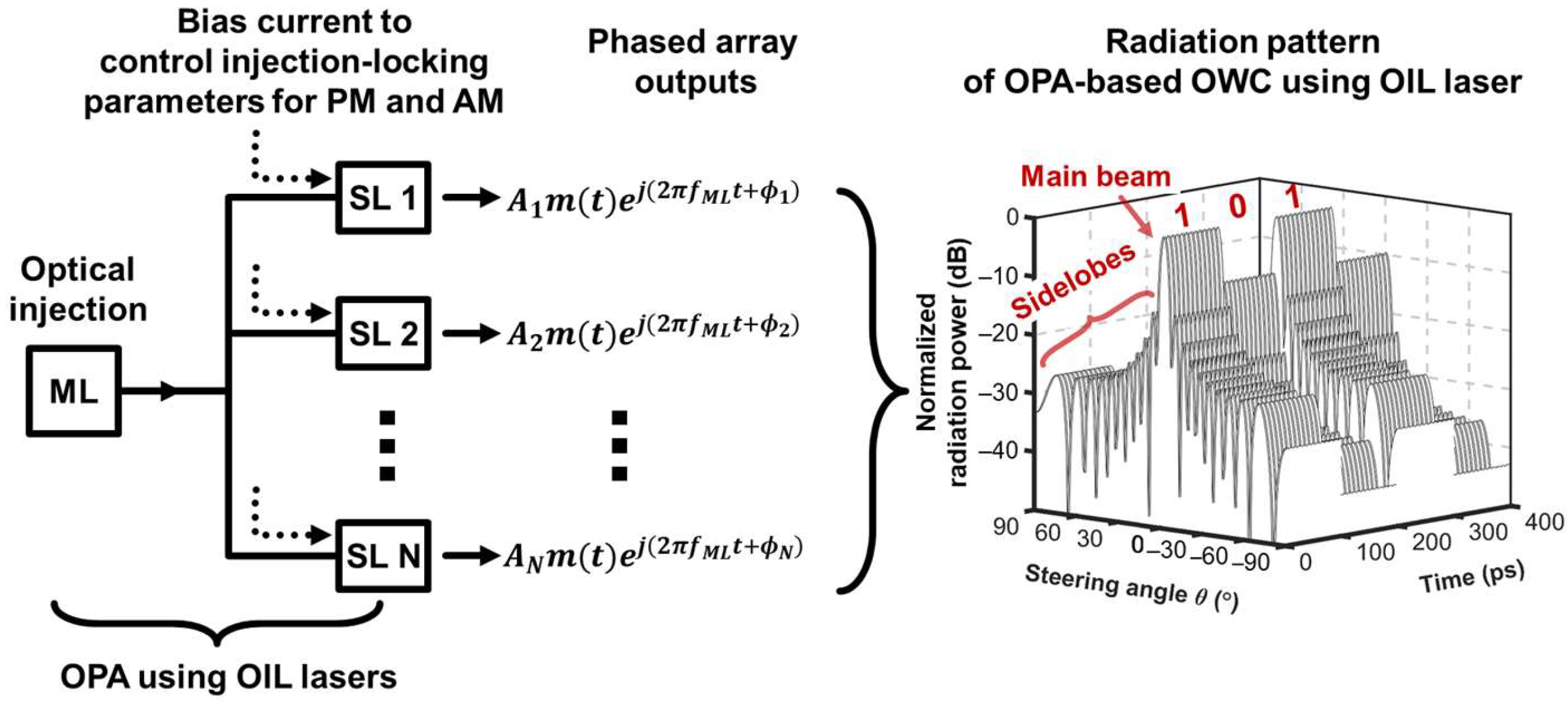
Figure 3 shows the schematic of the OPA with OIL semiconductor lasers and the radiation pattern of the OPA. An OIL semiconductor laser array is constructed using an ML and SLs. The far-field radiation pattern is formed by combining the array outputs radiated from the OPA elements.
Electrical beam steering and shaping can be achieved by the PM and AM of the OPA elements [41]. The optical signal of the ML with amplitude A M L , phase ϕ M L , and frequency f M L is injected into the SLs to achieve injection locking between the ML and each SL. When the optical injection-locking conditions are met, the optical outputs of the SLs are frequency locked to f M L . The optical injection-locking condition can be achieved by controlling two injection-locking parameters, i.e., the detuning frequency ( Δ f = f M L f f r e e , S L ) and injection power ratio ( R = A M L 2 / A f r e e , S L 2 = S M L / S f r e e , S L ). f f r e e , S L , A f r e e , S L , and S f r e e , S L denote the frequency, field amplitude, and photon number of a free-running SL, respectively, and S M L is the photon number of the ML. The amplitude and phase of an SL can be modulated by controlling the injection-locking parameters when the SL operates within a stable locking range. AM and PM can be achieved by adjusting the bias current of the SL [33,41].

4. Simulation Results

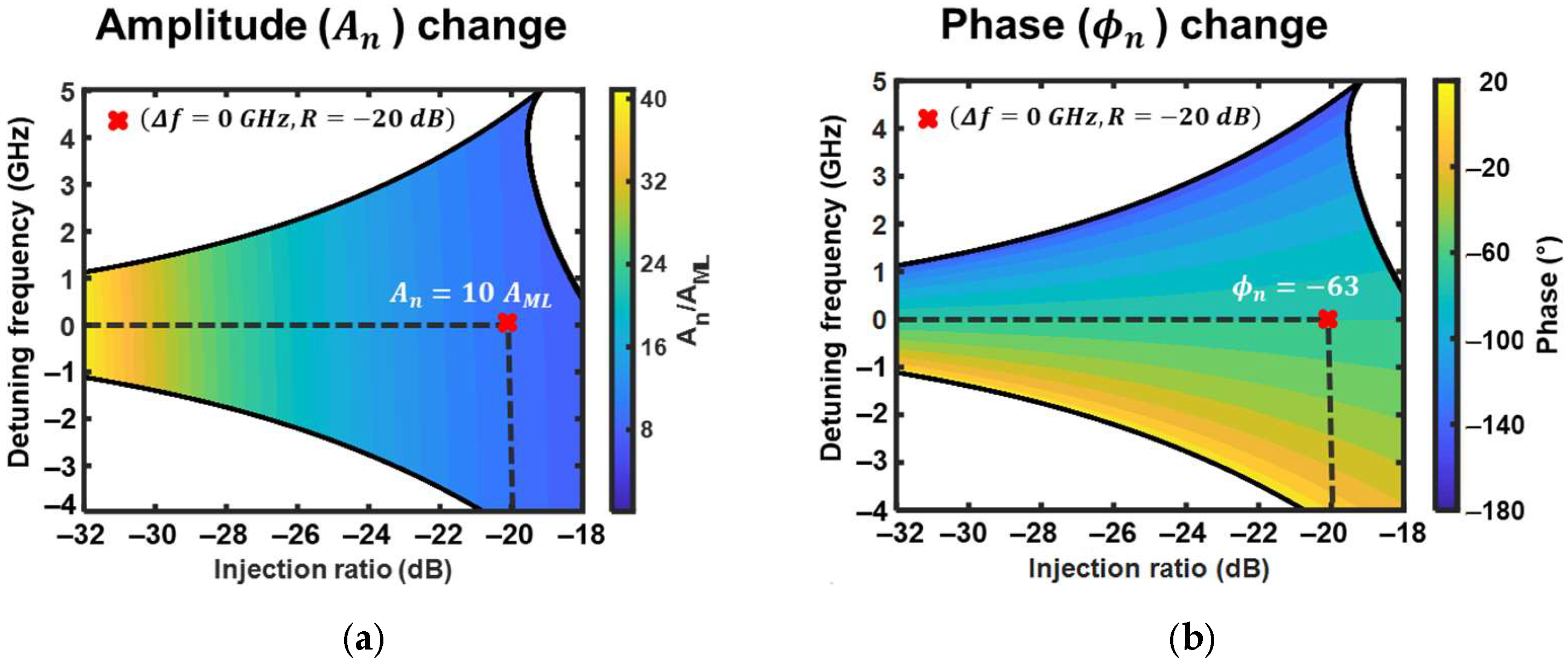
Figure 4 depicts the injection-locking map, which shows the dependence of the amplitude and phase of the OIL lasers on the injection-locking parameters.
The colored areas depict the stable locking regions. Figure 4a,b show the output amplitude and phase of the OIL lasers as functions of the injection-locking parameters, respectively. When an OIL laser is operated with two specific injection-locking parameters (e.g., Δ f = 0   GHz ,   R = 20   dB ), it provides an optical output signal with a corresponding pair of the amplitude and phase (e.g., A n = 10 A M L ,   ϕ n = 63 ° ). Consequently, we can achieve the target AM and PM of the OIL laser by controlling the injection-locking parameters. This is realized by modulating the bias current of the SL array. In real application, the look-up tables for each OIL-OPA element, which determine the relationship between the injection locking parameters and the amount of PM/AM of the injection-locked SL, should be experimentally obtained [33,41]. When the OIL laser array is used as the OPA elements, the beam shaping and steering of the OPA signal are realized by the AM and PM of the optical signal. The optical field of the OIL-based OPA Tx of the OWC system can be expressed as [41]
E t o t ( θ , t ) = n = 1 N m t A n exp j ( n 1 ) ( k d sin θ Δ ϕ ) exp j ω t ,
where m t is the message signal, A n is the optical amplitude weight of the nth SL, k is the wave number, d is the distance between adjacent SLs, θ is the steering angle, Δ ϕ is the phase difference between adjacent SLs, and ω is the optical angular frequency. The phase difference Δ ϕ between adjacent SLs is achieved by varying the phase of OPA element. The beam steering angle θ can be achieved by controlling Δ ϕ . A specific distribution of A n changes the shape of the far-field radiation pattern, as given by Equation (6). Hence, the SLL can be reduced by obtaining an appropriate amplitude distribution in the SL array. In this study, we bias the currents in the SL array to achieve a Taylor window distribution because we recently demonstrated that the OPA emitters with Taylor window distribution exhibit low SLL in the OPA far-field radiation pattern [41]. For communication purposes, we apply non-return-to-zero (NRZ) on–off keying (OOK) modulation to the OIL-based OPA. m t is added to the amplitude of each SL to modulate the optical signal. Therefore, we can achieve a low SLL and information modulation owing to the AM of the SL array. The PM of the SLs for beam steering can be achieved by selecting a suitable injection-locking condition and bias current. Finally, the simultaneous AM and PM of the OIL laser array (21 SLs) can be implemented to achieve beam steering and data transmission based on the OIL OPA with a high SLL reduction.
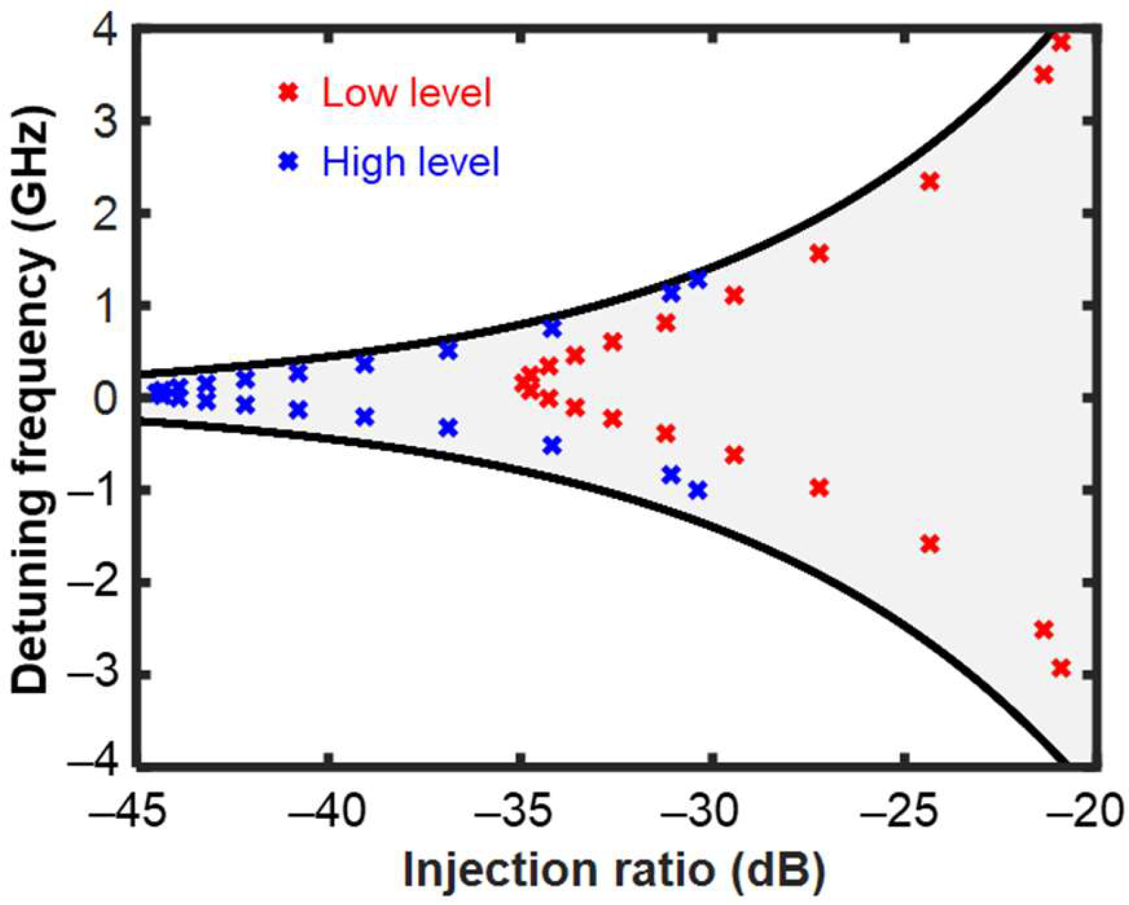
Figure 5 presents the injection-locking parameters for 21 SLs to achieve NRZ OOK modulation. First, we calculate the required AM and PM of 21 SLs to obtain the Taylor window function of amplitude profile and 6° of phase difference between adjacent SLs. Then we obtain the injection-locking parameters to achieve the required AM and PM. When the 21 SLs are operated under these parameters, we can simultaneously achieve NRZ OOK modulation, a low SLL, and beam steering (2° in this case). The beam steering range is controlled and enhanced by using an SL with low linewidth enhancement factor and/or cascaded OIL configuration [22,33,42]. The red and blue crosses correspond to the parameters calculated for high-level and low-level message signals, respectively. The steered beam can be modulated by switching the red and blue conditions. The OIL-OPA Tx is simulated with the ML operating at a frequency ( f M L ) of 1550 nm. The 21 SLs are located with a spacing of 775 nm between adjacent SLs.
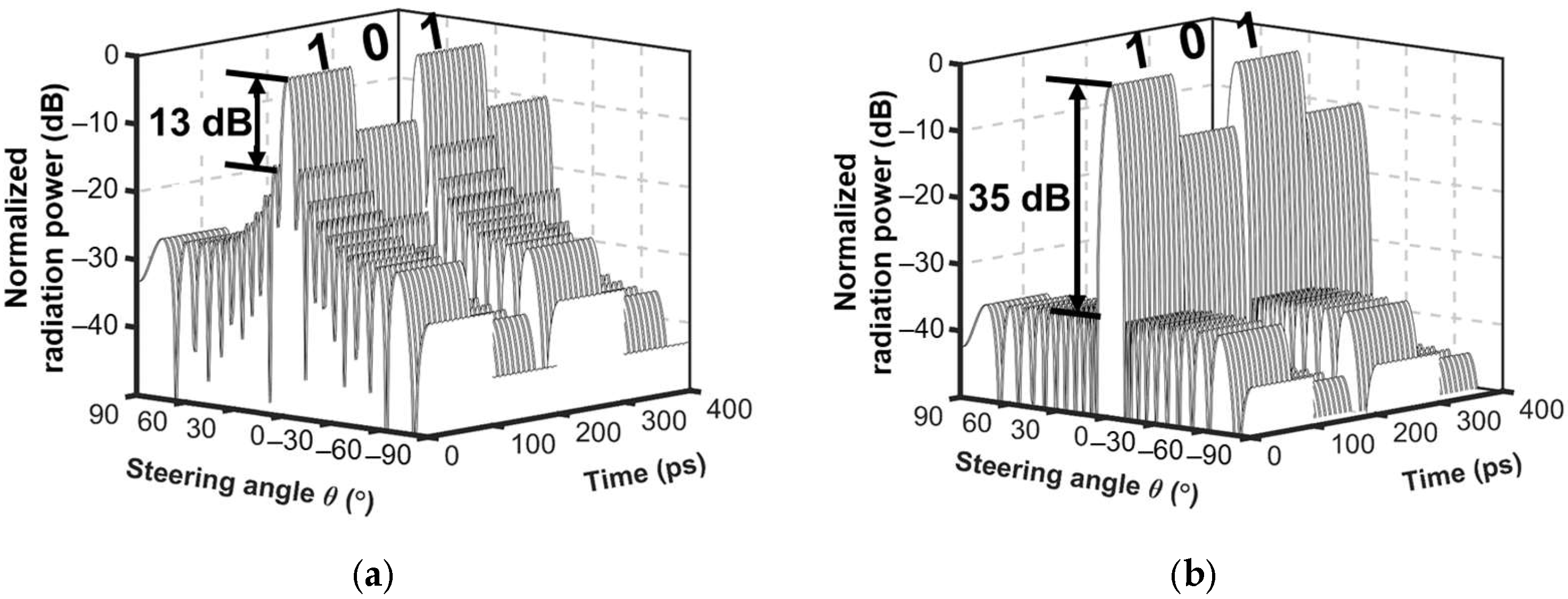
Figure 6a shows the modulated far-field radiation pattern of the Tx with a uniform amplitude distribution. The data rate is 10 Gbps. The SLL is relatively high at ~−13 dB. This might result in the transmission of the information signal in undesired directions because the sidelobe power is sufficiently high. Information may be detected from the sidelobes. The power of the sidelobes is reduced by applying the Tx with the Taylor window function as the amplitude distribution. The far-field radiation pattern achieved using the Taylor window function is shown in Figure 6b. The SLL is reduced by 22 dB compared to the case with the uniform amplitude distribution.
We steer the beam by 2° during transmission. The significant suppression of the sidelobe power in the far-field radiation pattern reduces the unsecured distance.
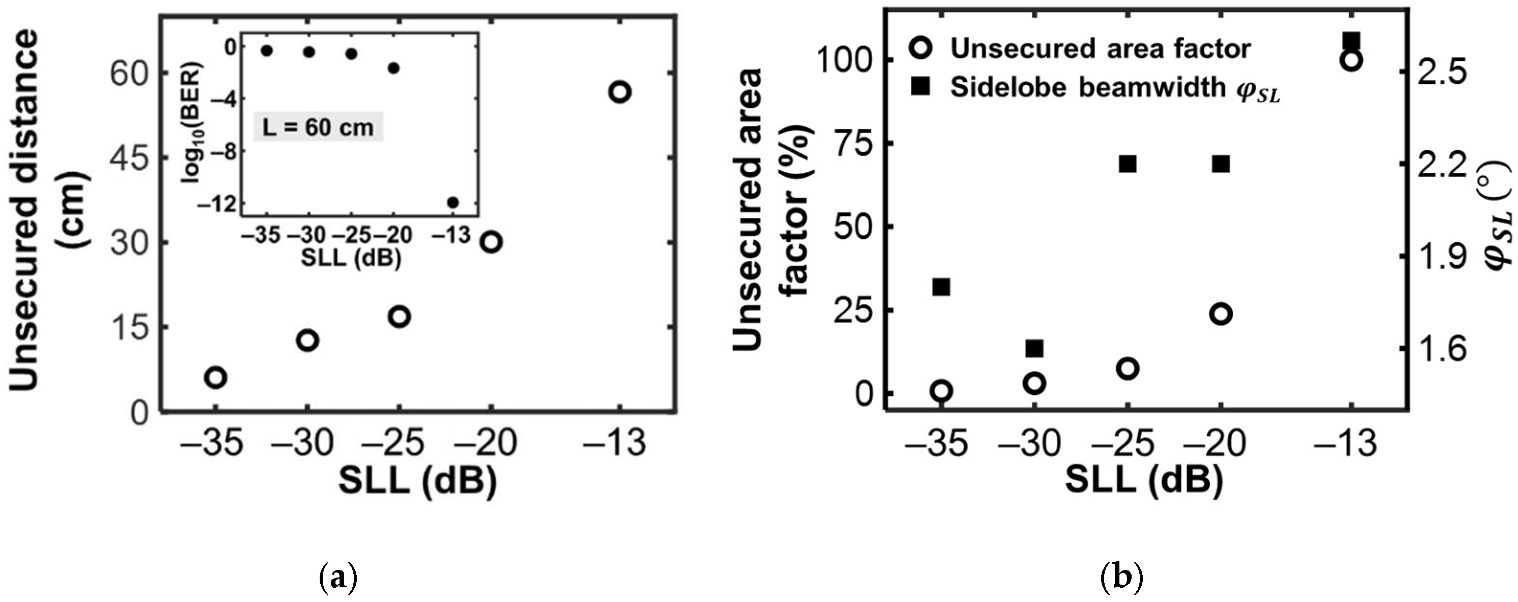
Based on the improved beam performance in terms of the SLL reduction, we evaluate the beam security performance as a function of the SLL. Figure 7a shows the unsecured distance calculated using Equations (1)–(4). The unsecured distance obtained with the Taylor window function is reduced by more than 10 times compared to the case without the Taylor window function. The inset of Figure 7a shows the BER dependence on SLL for the fixed transmission length of 60 cm. The BER for the data transmission via sidelobe increases when SLL is low, which confirms the improved security performance. We define the unsecured area factor as follows:
Unsecured   area   factor   ( % ) = S u n , max , T a y l o r S u n , max , u n i f o r m × 100 % ,
where S u n , max , u n i f o r m and S u n , max , T a y l o r are the maximum unsecured areas for the uniform amplitude and Taylor window function profiles, respectively. The reduction in the unsecured area factor represents the improvement of the OWC system security by the Taylor window function profile. The relationship between the parameters of the sidelobes and the unsecured area can be derived from Equations (1)–(5). We can conclude that the OWC system security can be improved by suppressing the OPA sidelobes in the far-field radiation pattern. Figure 7b shows the unsecured area factor (circle) calculated using Equations (1)–(5) and (7) to demonstrate the improvement of the OWC system security. The unsecured area factor is significantly reduced when the SLL is suppressed by the Taylor window function. It is 0.8% when the Taylor window function is used. The right-hand y-axis exhibits dependence of the sidelobe beamwidth φ S L (square dots) on the SLL. We found that the sidelobe beamwidth φ S L reduces with increasing sidelobe intensity. We confirm that the security performance represented by Equation (5) improves owing to the application of Taylor window function and the resultant SLL reduction. Therefore, we can improve the OWC system security using the proposed OIL-OPA Tx owing to the reduction in the SLL. In addition, we achieve a simple configuration and low power consumption of the OWC system.

5. Conclusions

We proposed an OWC system with an OIL-OPA transmitter and analyzed its security performance. The AM and PM of the OIL-OPA transmitter could be simultaneously achieved by controlling the bias current of OIL semiconductor lasers. The SLL was significantly suppressed by applying a Taylor window function as the amplitude profile of the OIL-OPA transmitter. Furthermore, the unsecured area was reduced. We calculated the injection-locking parameters for the desired AM/PM to simultaneously achieve a low SLL, beam steering, and data modulation. We achieved a high SLL reduction of 35 dB at a beam steering of 2° and a data transmission rate of 10 Gbps using suitable injection-locking parameters, the Taylor window function, and a phase difference of 6° between adjacent SLs. Furthermore, when the Taylor window function was used, the unsecured distance decreased by ten times compared to the case without the Taylor window function. In addition, the unsecured area factor was 0.8%. The OIL-OPA transmitters with improved security performance, a simple configuration, and low power consumption can be widely used in various photonic applications, including military and medical optical/wireless applications.

Author Contributions

All authors contributed considerably to this study. Conceptualization, H.-K.S., J.-H.C. and A.-H.N.; simulation and analysis, J.-H.C. and A.-H.N.; writing—original draft preparation, J.-H.C. and A.-H.N.; writing—review and editing, H.-K.S.; visualization, H.-K.S.; supervision, H.-K.S. All authors have read and agreed to the published version of the manuscript.

Funding

This research was funded by the National Research Foundation of Korea (NRF) under the Basic Science Research Program (NRF-2019R1F1A1040959 and NRF-2021R1F1A104591911).

Institutional Review Board Statement

Not applicable.

Informed Consent Statement

Not applicable.

Data Availability Statement

Not applicable.

Conflicts of Interest

The authors declare no conflict of interest. The funders had no role in the study design; in the collection, analyses, or interpretation of data; in the writing of the manuscript; or in the decision to publish the results.

References

  1. Uysal, M.; Capsoni, C.; Ghassemlooy, Z.; Boucouvalas, Z.; Udvary, A. Optical Wireless Communications, 1st ed.; Springer International Publishing: Cham, Switzerland, 2016; pp. 2–5. [Google Scholar]
  2. Karagiannidis, G.K.; Arnon, S.; Barry, J.R.; Schober, R.; Uysal, M. Guest editorial: Optical wireless communications. IEEE J. Sel. Areas Commun. 2009, 27, 1521–1525. [Google Scholar] [CrossRef]
  3. Chowdhury, M.Z.; Hossan, M.T.; Islam, A.; Jang, Y.M. A comparative survey of optical wireless technologies: Architectures and applications. IEEE Access 2018, 6, 9819–9840. [Google Scholar] [CrossRef]
  4. Mahdy, A.; Deogun, J.S. Wireless Optical Communications: A Survey. In Proceedings of the IEEE Wireless Communications and Networking Conference, Atlanta, GA, USA, 21–25 March 2004. [Google Scholar]
  5. Uysal, M.; Nouri, H. Optical Wireless Communications—An Emerging Technology. In Proceedings of the 16th International Conference on Transparent Optical Networks (ICTON), Graz, Austria, 6–10 July 2014. [Google Scholar]
  6. Harald, H.; Jaafar, E.; Ian, W. Optical wireless communication. Philos. Trans. R. Soc. A 2020, 378, 1–11. [Google Scholar]
  7. Malik, A.; Singh, P. Free space optics: Current applications and future challenges. Int. J. Opt. 2015, 2015, 945483. [Google Scholar] [CrossRef] [Green Version]
  8. Gursale, V.M.; Patil, S.S.; Kakade, A.B. Enhancement in free space optical communication: A review. IJARCCE 2016, 5, 65–71. [Google Scholar]
  9. Hranilovic, S. Wireless Optical Communication Systems, 1st ed.; Springer: New York, NY, USA, 2005; pp. 3–8. [Google Scholar]
  10. Zhang, Z.; Dang, J.; Wu, L.; Wang, H.; Xia, J.; Lei, W.; Wang, J.; You, X. Optical mobile communications: Principles, implementation, and performance analysis. IEEE Trans. Veh. Technol. 2019, 68, 471–482. [Google Scholar] [CrossRef]
  11. Heck, M.J.R. Highly integrated optical phased arrays: Photonic integrated circuits for optical beam shaping and beam steering. Nanophotonics 2017, 1, 93–107. [Google Scholar] [CrossRef]
  12. Poulton, C.V.; Byrd, M.J.; Russo, P.; Timurdogan, E.; Khandaker, M.; Vermeulen, D.; Watts, M.R. Long-range LiDAR and free-space data communication with high-performance optical phased arrays. IEEE J. Sel. Top. Quantum Electron. 2019, 25, 1–8. [Google Scholar] [CrossRef]
  13. He, J.; Dong, T.; Xu, Y. Review of Photonic Integrated Optical Phased Arrays for Space Optical Communication. IEEE Access 2020, 8, 188284–188298. [Google Scholar] [CrossRef]
  14. Zang, H.; Zang, Z.; Lv, J.; Peng, C.; Hu, W. Fast beam steering enabled by a chip-scale optical phased array with 8 × 8 elements. Opt. Commun. 2020, 461, 12567. [Google Scholar]
  15. Gozzard, D.R.; Roberts, L.E.; Spollard, J.T.; Sibley, P.G.; Shaddock, D.A. Fast beam steering with an optical phased array. Opt. Lett. 2020, 45, 3793–3796. [Google Scholar] [CrossRef] [PubMed]
  16. Hosseini, A.; Kwong, D.; Chen, R.T. Wide steering angle optical phased array based on silicon nano-membrane. In Photonics Packaging, Integration, and Interconnects IX, Proceedings of the SPIE: Integrated Optoelectronic Devices, San Joe, CA, USA, 12 February 2009; International Society for Optics and Photonics: Bellingham, WA, USA, 2009; Volume 7221, p. 72210T. [Google Scholar]
  17. Roberts, L.E.; Ward, R.L.; Francis, S.P.; Sibley, P.G.; Fleddermann, R.; Sutton, A.J.; Smith, C.; McClelland, D.E.; Shaddock, D.A. High power compatible internally sensed optical phased array. Opt. Express 2016, 24, 13467–13479. [Google Scholar] [CrossRef]
  18. Huang, W.R.; Montoya, J.; Kansky, J.E.; Redmond, S.M.; Turner, G.W.; Sanchez-Rubio, A. High speed, high power one-dimensional beam steering from a 6-element optical phased array. Opt. Express 2012, 20, 17311–17318. [Google Scholar] [CrossRef] [PubMed]
  19. Roberts, L.E.; Ward, R.L.; Smith, C.; Shaddock, D.A. Coherent Beam Combining Using an Internally Sensed Optical Phased Array of Frequency-Offset Phase Locked Lasers. Photonics 2020, 7, 118. [Google Scholar] [CrossRef]
  20. Guo, Y.; Guo, Y.; Li, C.; Zhang, H.; Zhou, X.; Zhang, L. Integrated Optical Phased Arrays for Beam Forming and Steering. Appl. Sci. 2021, 11, 4017. [Google Scholar] [CrossRef]
  21. Stulemeijer, J.; van Vliet, F.E.; Benoist, K.W.; Maat, D.H.P.; Smit, M.K. Compact photonic integrated phase and amplitude controller for phased-array antennas. IEEE Photonics Technol. Lett. 1999, 11, 122–124. [Google Scholar] [CrossRef] [Green Version]
  22. Sayyah, K.; Efimov, O.; Patterson, P.; Schffner, J.H. Two-dimensional pseudo-random optical phased array based on tandem optical injection locking of vertical cavity surface emitting lasers. Opt. Express 2015, 23, 19405–19416. [Google Scholar] [CrossRef]
  23. Abedasl, H.; Hashemi, H. Monolithic optical phased-array transceiver in a standard SOI CMOS process. Opt. Express 2015, 23, 6509–6519. [Google Scholar] [CrossRef]
  24. Sabouri, S.; Jamshidi, K. Design considerations of silicon nitride optical phased array for visible light communications. IEEE J. Sel. Top. Quantum Electron. 2018, 24, 1–7. [Google Scholar] [CrossRef]
  25. Doylend, J.K.; Heck, M.J.R.; Bovington, J.T.; Peters, J.D.; Coldren, L.A.; Bowers, J.E. Two-dimensional free-space beam steering with an optical phased array on silicon-on-insulator. Opt. Express 2011, 19, 21595–21604. [Google Scholar] [CrossRef] [Green Version]
  26. Zhu, Y.; Ju, Y.; Wang, B.; Cryan, J.; Zhao, B.Y.; Zheng, H. Wireless side-lobe eavesdropping attacks. arXiv 2018, arXiv:1810.10157. [Google Scholar]
  27. Balakrishnan, S.; Wang, P.; Bhuyan, A.; Sun, Z. Modeling and analysis of eavesdropping attack in 802.11ad mmWave wireless networks. IEEE Access 2019, 7, 70355–70370. [Google Scholar] [CrossRef]
  28. Hong, Y.; Jing, X.; Gao, H.; He, Y. Fixed region beamforming using frequency diverse subarray for secure mmWave wireless communications. IEEE Trans. Inf. Forensics Secur. 2020, 15, 2706–2721. [Google Scholar] [CrossRef]
  29. Kwong, D.; Hosseini, A.; Zhang, Y.; Chen, R.T. 1 × 12 Unequally spaced waveguide array for actively tuned optical phased array on a silicon nanomembrane. Appl. Phys. Lett. 2011, 99, 51104. [Google Scholar] [CrossRef] [Green Version]
  30. Sun, J.; Hosseini, E.S.; Yaacobi, A.; Cole, D.B.; Leake, G.; Coolbaugh, D.; Watts, M.R. Two-dimensional apodized silicon photonic phased arrays. Opt. Lett. 2014, 39, 367–370. [Google Scholar] [CrossRef]
  31. Dregely, D.; Taubert, R.; Dorfmuller, J.; Vogelgesang, R.; Kern, K.; Giessen, H. 3D optical Yagi–Uda nanoantenna array. Nat. Commun. 2011, 2, 267. [Google Scholar] [CrossRef] [Green Version]
  32. Yifat, Y.; Eitan, M.; Lluz, Z.; Hanein, Y.; Boag, A.; Scheuer, J. Highly Efficient and Broadband Wide-Angle Holography Using Patch-Dipole Nanoantenna Reflectarrays. Nano Lett. 2014, 14, 2485–2490. [Google Scholar] [CrossRef] [Green Version]
  33. Cho, J.H.; Cho, C.H.; Sung, H.K. Theoretical performance evaluation of optical complex signals based on optically injection-locked semiconductor lasers. IEEE J. Sel. Top. Quantum Electron. 2019, 25, 1–9. [Google Scholar] [CrossRef]
  34. Lau, E.K.; Wong, L.J.; Wu, M.C. Enhanced modulation characteristics of optical injection-locked lasers: A tutorial. IEEE J. Sel. Top. Quantum Electron. 2009, 15, 618–633. [Google Scholar] [CrossRef]
  35. Lucente, M.; Kintzer, E.S.; Alexander, S.B.; Fujimoto, J.G.; Chan, V.W. Coherent Optical Communication with an Injection-Locked High Power Diode Laser Array. In Proceedings of the Conference on Lasers and Electro-Optics, Baltimore, MD, USA, 24 April 1989. [Google Scholar]
  36. Ying, C.L.; Lu, H.H.; Li, C.Y.; Cheng, C.J.; Peng, P.C.; Ho, W.J. 20-Gbps optical LiFi transport system. Opt. Lett. 2015, 40, 3276–3279. [Google Scholar] [CrossRef]
  37. Hasebe, K.; Koyama, F. All-optical signal processing based on optical injection-locked two-mode vertical-cavity surface-emitting laser. In Physics and Simulation of Optoelectronic Devices XIV, Proceedings of the SPIE: Integrated Optoelectronic Devices 2006, San Joe, CA, USA, 28 February 2006; International Society for Optics and Photonics: Bellingham, WA, USA, 2006; Volume 6115. [Google Scholar]
  38. Goldberg, L.; Taylor, H.F.; Weller, J.F.; Bloom, D.M. Microwave signal generation with injection locked laser diodes. Electron. Lett. 1983, 19, 491–493. [Google Scholar] [CrossRef]
  39. Keiser, G. Optical Fiber Communications, 5th ed.; McGraw Hill: Singapore, 2015; pp. 267–308. [Google Scholar]
  40. Dai, H.; Li, D.; Wong, R.C. Exploring Security Improvement of Wireless Networks with Directional Antennas. In Proceedings of the IEEE 36th Conference on Local Computer Networks, Bonn, Germany, 4–7 October 2011. [Google Scholar]
  41. Nguyen, A.H.; Cho, J.H.; Bae, H.J.; Sung, H.K. Side-lobe level reduction of an optical phased array using amplitude and phase modulation of array elements based on optically injection-locked semiconductor lasers. Photonics 2020, 20, 20. [Google Scholar] [CrossRef] [Green Version]
  42. Mogensen, F.; Olesen, H.; Jacobsen, G. Locking conditions and stability properties for a semiconductor laser with external light injection. IEEE J. Quantum Electron. 1985, 21, 784–793. [Google Scholar] [CrossRef]
Figure 1. Elements and transmission beam shape of optical wireless communication system based on optical phased array; Tx: transmitter, Rx: receiver.
Photonics 08 00469 g001
Figure 2. Conceptual diagram for calculating unsecured length and unsecured area factor.
Photonics 08 00469 g002
Figure 3. Schematic of OPA-based OWC with OIL semiconductor lasers. ML: master laser, SL: slave laser, OIL laser: optically injection-locked laser, PM: phase modulation, AM: amplitude modulation.
Photonics 08 00469 g003
Figure 4. Injection-locking map exhibiting the dependence of the (a) amplitude and (b) phase of the OIL lasers on the injection-locking parameters.
Photonics 08 00469 g004
Figure 5. Calculated injection-locking parameters for 21 SLs for non-return-to-zero on–off keying modulation. Red and blue crosses correspond to the conditions for low-level and high-level signals, respectively.
Photonics 08 00469 g005
Figure 6. Modulated far-field radiation pattern of OIL-OPA Tx for OWC. (a) OPA Tx with uniform amplitude distribution; (b) OPA Tx with Taylor window function.
Photonics 08 00469 g006
Figure 7. (a) Unsecured distance as a function of the sidelobe level (SLL) and inset: BER as a function of SLL for a transmission length of 60 cm; (b) Unsecured area factor (circle) and sidelobe beamwidth φ S L (square dots) as a function of the SLL.
Photonics 08 00469 g007
Publisher’s Note: MDPI stays neutral with regard to jurisdictional claims in published maps and institutional affiliations.