Article

Design and Simulation of an Ultra-Wide Field Optical Coherence Tomography Retinal Imaging System

1
National Innovation Center for Advanced Medical Devices, Shenzhen 518131, China
2
GBA Branch of Aerospace Information Research Institute, Chinese Academy of Sciences, Guangzhou 510530, China
3
School of Electronics and Information Technology, Sun Yat-sen University, Guangzhou 510006, China
4
School of Physics, Sun Yat-sen University, Guangzhou 510006, China
5
School of Artificial Intelligence, Guilin University of Electronic Technology, Guilin 541004, China
*
Author to whom correspondence should be addressed.
These authors contributed equally to this work.
Photonics 2021, 8(11), 476; https://doi.org/10.3390/photonics8110476
Submission received: 30 August 2021 / Revised: 23 October 2021 / Accepted: 25 October 2021 / Published: 27 October 2021
(This article belongs to the Special Issue Tissue Optics)

Abstract

:
Peripheral retinal imaging is a unique approach for assessing and monitoring ocular diseases. In this paper, we proposed a design for an optical coherence tomography system to accomplish ultrawide field (>120°) retinal imaging without montages. Scanning of the sample arm was achieved via two ellipsoidal mirrors. The optical design software Zemax and an eye model were used to estimate the inherent aberrations in the system and the optical performance of retinal imaging. Simulation results of the aberrations in the designed system indicated that the designed system can achieve an unprecedented imaging field of view (FOV) while maintaining acceptable resolution without sacrificing the working distance. This work suggests that ultrawide field optical coherence tomography retinal imaging is achievable, which is highly important for the diagnosis and treatment of ocular—especially peripheral—retinopathy.

1. Introduction

Optical coherence tomography (OCT) is a biomedical optical imaging technology developed in the 1990s [1]. Based on the principle of low coherence interference, this technique allows high-resolution depth information to be obtained. Due to the transparency of the eye, ophthalmological applications, especially retinal imaging, were not only the earliest but are also the most successful clinical applications [2]. Although OCT imaging technology has been widely used in ophthalmology, it is used mainly to visualize the central area of the retina and rarely used to visualize the peripheral area of the retina.
In fact, many vision-threatening pathologies, including retinal tears, holes, detachments, etc., occur in the peripheral retina [3], and the development of some central ocular diseases (such as diabetic retinopathy) is closely related to the state of the peripheral retina [4]. However, only a few existing OCT techniques can successfully achieve high-quality imaging of the peripheral retina. Currently, the field of view (FOV) of commercial OCT imaging equipment is generally in the range of 30~55°. Wide field OCT imaging technology has only recently attracted people’s attention. The most typical method used for wide field retinal imaging is the montage method. In 2011, the first work on the montage of an OCT dataset was presented [5]; images with an FOV of 50° × 35° were obtained. Since that study, many stitched OCT techniques have appeared sequentially [6,7,8]. Based on this method, ultrawide field (up to 200°) OCT retinal images are currently available [8]. However, this method has considerable limitations. First, it can be performed only by experienced physicians. Second, the rotation of the steering head or patient limits the range and speed of imaging. Third, image processing is time-consuming, and the image quality depends on the accuracy of registration. In general, the registration error of large FOV stitching is 45–60 μm [5]. In 2011, Huber et al. achieved 70° ultrawide field retinal imaging in a single shot using a doublet similar to a Plössl eyepiece design in the sample arm [9]. Due to the limitation of the optical power of the lens, the FOV was greatly limited such that the maximum FOV was approximately 70°. In addition, because of the inherent optical properties of the spherical lens, the aberration at the edge of the image was very large. Later, a research group used the Volk Super Pupil XL commercial fundus lens as the eyepiece in the sample arm and accomplished 100° ultrawide field retinal imaging [10]. The main defect in this scheme was that the working distance was very small (4–5 mm), which causes the patient great discomfort. Recently, Izatt et al. added adaptive optics (AO) to a wide field retinal OCT system [11], thereby improving the quality of the obtained OCT images. However, addition of an AO system greatly increases the cost and sampling time of the system. Moreover, the imaging FOV is also limited by the design of the eyepieces. In laser fundus imaging technology, a design based on an ellipsoidal scanning structure was adopted to obtain fundus images with an ultrawide FOV [12].
In this paper, we proposed a design of an OCT system (mainly the sample arm) based on two ellipsoidal mirrors and carried out a simulation with the optical design software Zemax. In addition, based on an eye model, the aberration in the designed system was compared with that in the conventional system. The designed system accomplished ultrawide field retinal imaging over a span of greater than 110° in the vertical direction and 200° in the horizontal direction. Moreover, this system overcame the problem of severe aberration without reducing the working distance.

2. Design of the Ultrawide Field OCT Retinal Imaging System

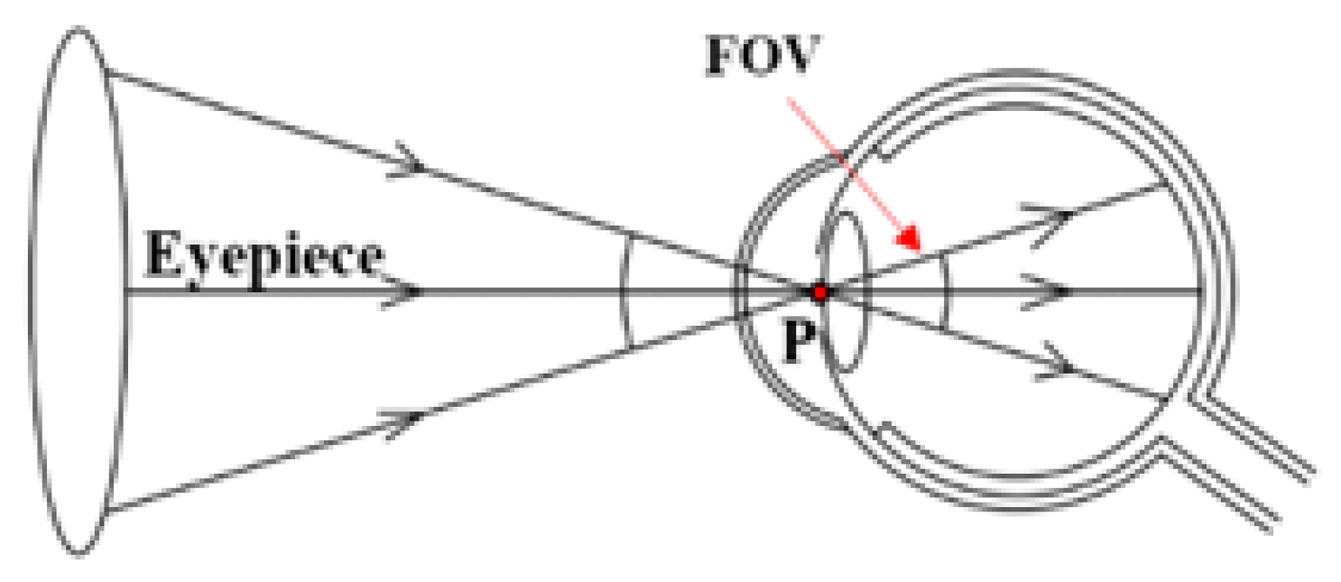
2.1. Definition of the FOV

Currently, there is no clear definition of the FOV of an OCT imaging system. Here, we provide a general reference for the FOV of a point scanning OCT system. Generally, a point scanning system includes a scanning device based on a mechanical rotating reflector, such as a galvanometer. When light beams at different angles enter the eye, the center rays of all scanning beams pass through a common point (see Figure 1, point “P”), which can be called the pivot point [10]. Considering the limitation of the pupil size of the eye and maximization of the scanning range, the pivot point in the OCT system is usually located at the pupil or node point of the eye. Therefore, when comparing the imaging range of OCT systems, it is important to determine the location of the pivot point. For the same incidence angle, the actual imaging range is larger when the pivot point is located at the pupil than at the node point.
The angle between the most marginal imaging beams is defined as the FOV of a traditional fundus camera [13], which is essentially consistent with that of OCT systems. In 1926, the Carl Zeiss company produced the first commercially available fundus camera with a 20° FOV. Later, they standardized 30° as the ‘‘normal’’ FOV of the fundus camera. Subsequently, an imaging angle greater than this standard was defined as ‘‘wide field’’ or ‘‘wide angle’’. This definition can also be applied to OCT; in 2015, a study by the Diabetic Retinopathy Clinical Research Network clearly defined that an FOV of greater than 100° in a fundus photograph was called an “ultrawide field” [14].

2.2. Resolution of the OCT System
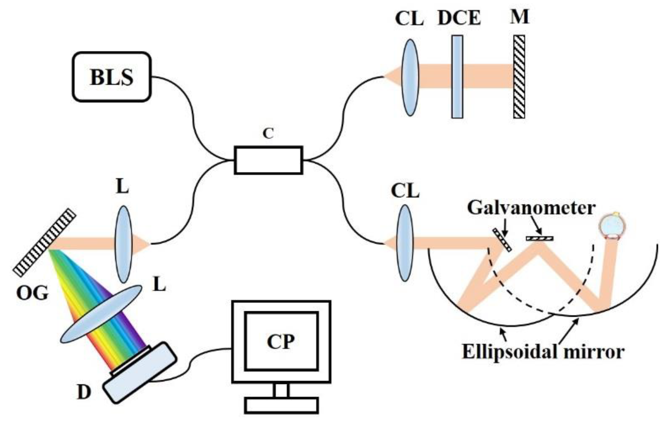
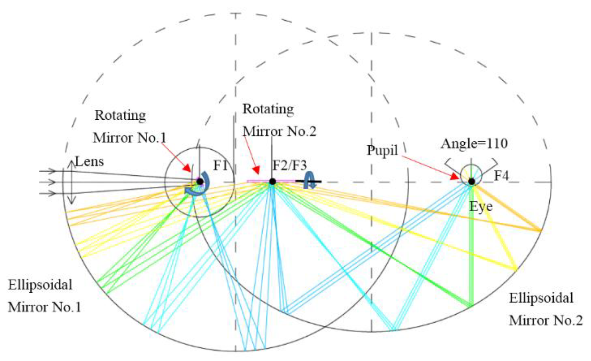
OCT provides depth-resolved information of the sample based on coherence gating; its axial resolution is decoupled from its lateral resolution. The axial resolution of OCT is primarily determined by the bandwidth of the light source, as illustrated by the following equation:
ΔL = (2ln(2)/π) · (λc2/Δλ)
where λc and ∆λ are the central wavelength and the optical bandwidth of the source, respectively [15].
The lateral resolution depends on the wavelength (λ) and beam size (d) as well as the objective’s focal length (f) and can be given as shown below:
∆d = 4λf/πd
A high axial resolution can be guaranteed by selecting a light source with a wide bandwidth. Therefore, we mainly discuss the lateral resolution of the system. Next, we present the design of the ultrawide field OCT retinal imaging system and a lateral resolution analysis of the system through Zemax simulation.

2.3. System Design

The design of the sample arm is the main concern because the sample arm is the determinant of an ultrawide FOV. The rest of the system can be configured similar to a conventional OCT system, as shown in Figure 2.
A schematic diagram of the designed sample arm is shown in Figure 3. The key elements are two ellipsoidal mirrors with appropriate focal lengths and relative positions. Considering the working distance and the physiological structure of the human body, the two ellipsoid formulas for ellipsoidal mirrors no. 1 and no. 2 were selected as follows:
(x2/2002) + (y2/195.62) = 1
(x2/2082) + (y2/1732) = 1
The scanning system in sample arm is presented in Figure 3, where the long axes of the two ellipsoidal mirrors are collinear. The first focal point of ellipsoidal mirror no. 2 (F3) was located at the second focal point of ellipsoidal mirror no. 1 (F2). The two scanning galvanometer were located at F1 and F2/F3. The eye was positioned at the second focal point of ellipsoidal mirror no. 2 (F4). The parallel beams from the collimator first passed through a coupling lens (“Lens” in Figure 3), which had a focal length of 200 mm and was located 148.151 mm from F1. Then, the beams were reflected sequentially by rotating mirror no. 1, ellipsoidal mirror no. 1, rotating mirror no. 2 and ellipsoidal mirror no. 2. Finally, the beams entered the eye in parallel and were focused on the retina. When the rotating mirrors were scanning, ultrawide field retinal imaging was achieved. Ray tracing (as shown in Figure 3) showed that this system can generate a retinal image with an FOV of up to 110° in the vertical direction (upper to lower). Scanning of rotating mirror no. 2 performed imaging in the horizontal direction (nasal to temporal). If the scanning angle of the rotating mirror is large enough, the horizontal imaging range can cover up to 200° (not shown in Figure 3). In addition, the system does not require pupil dilation.

3. Simulation Methods

The optical design software Zemax was used to perform optical simulations for the designed system. The incident spot diameter was set to 25.75 mm. Three wavelengths, 760 nm, 860 nm and 960 nm, were selected as the working wavelengths. An eye model presented by the Izatt group in 2015 [16] was selected. Only an ideal lens with a focal length of 16.05 mm (the focal length of the eye) was used to study the inherent aberrations in the system. Since the eye model cannot be applied in reverse, the total aberration in the retinal imaging system was evaluated by using the ideal lens and wavefront differences (Zernike standard coefficients) generated from the eye model. The input parameters of the Lens Data Editor in Zemax are shown in Supplementary Materials. Figure 4 shows the 3D layout and shaded model (in the vertical shaded model, only beams in the central FOV are displayed to avoid occlusion).

4. Results and Comparison

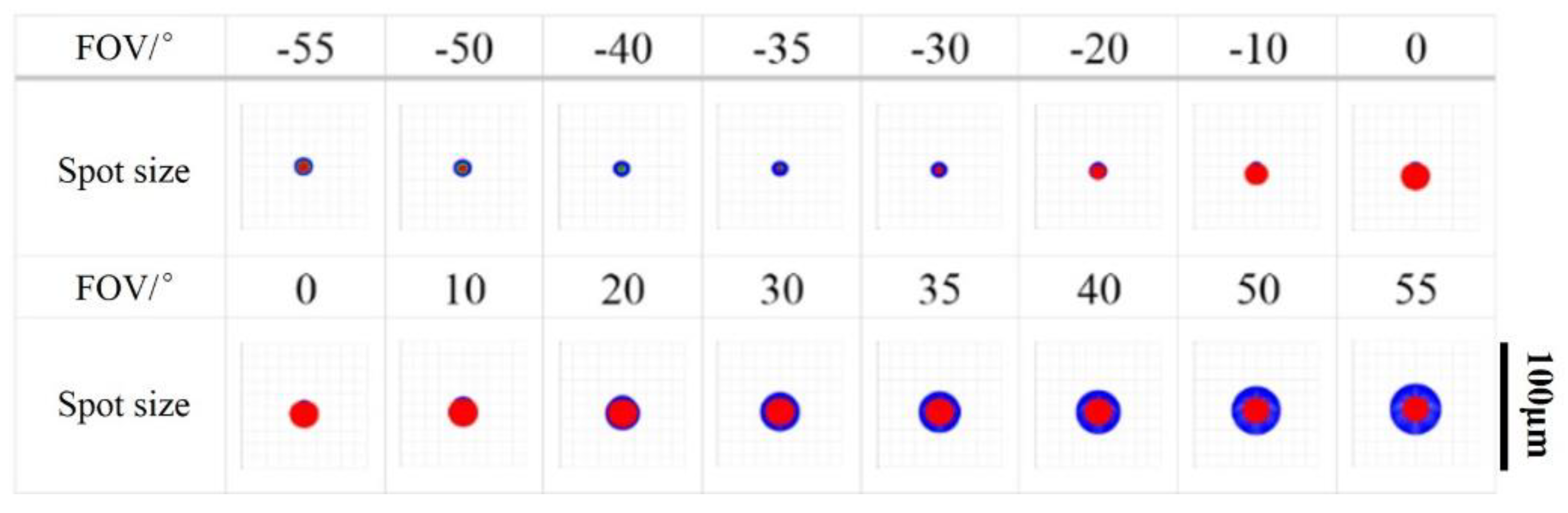
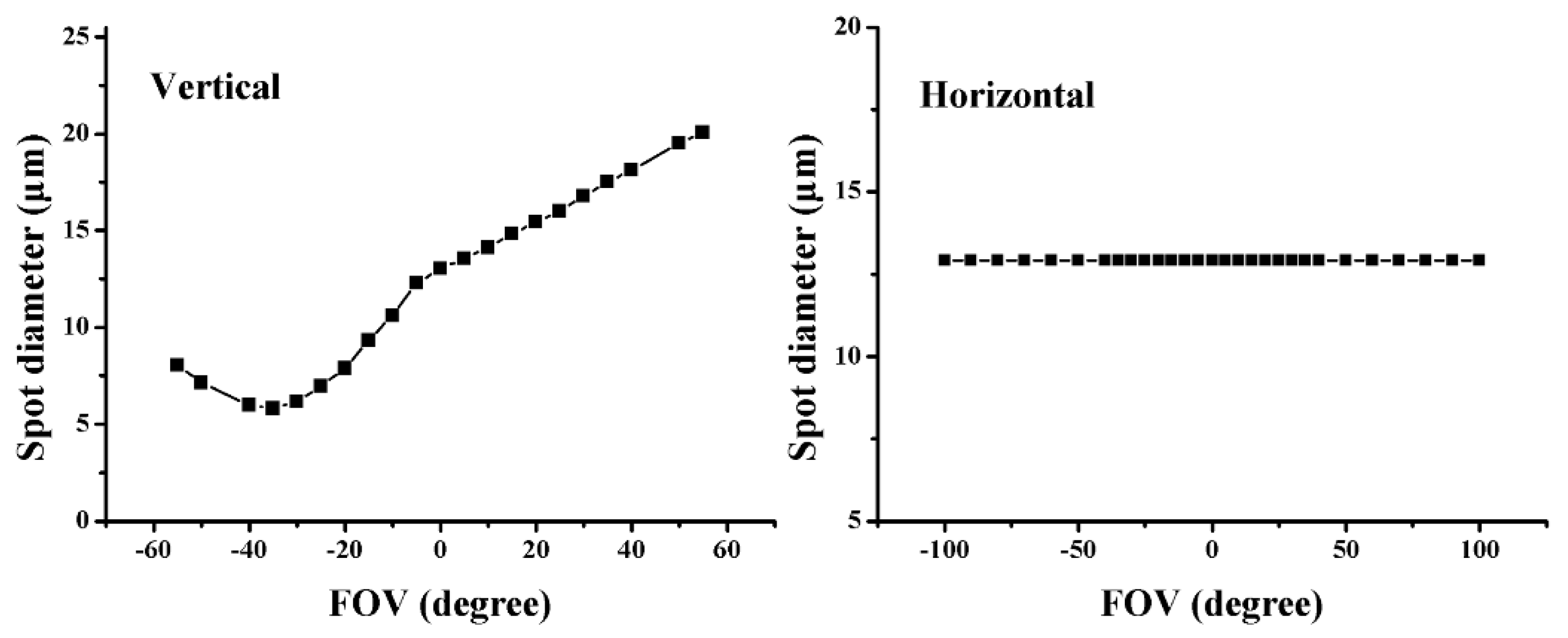
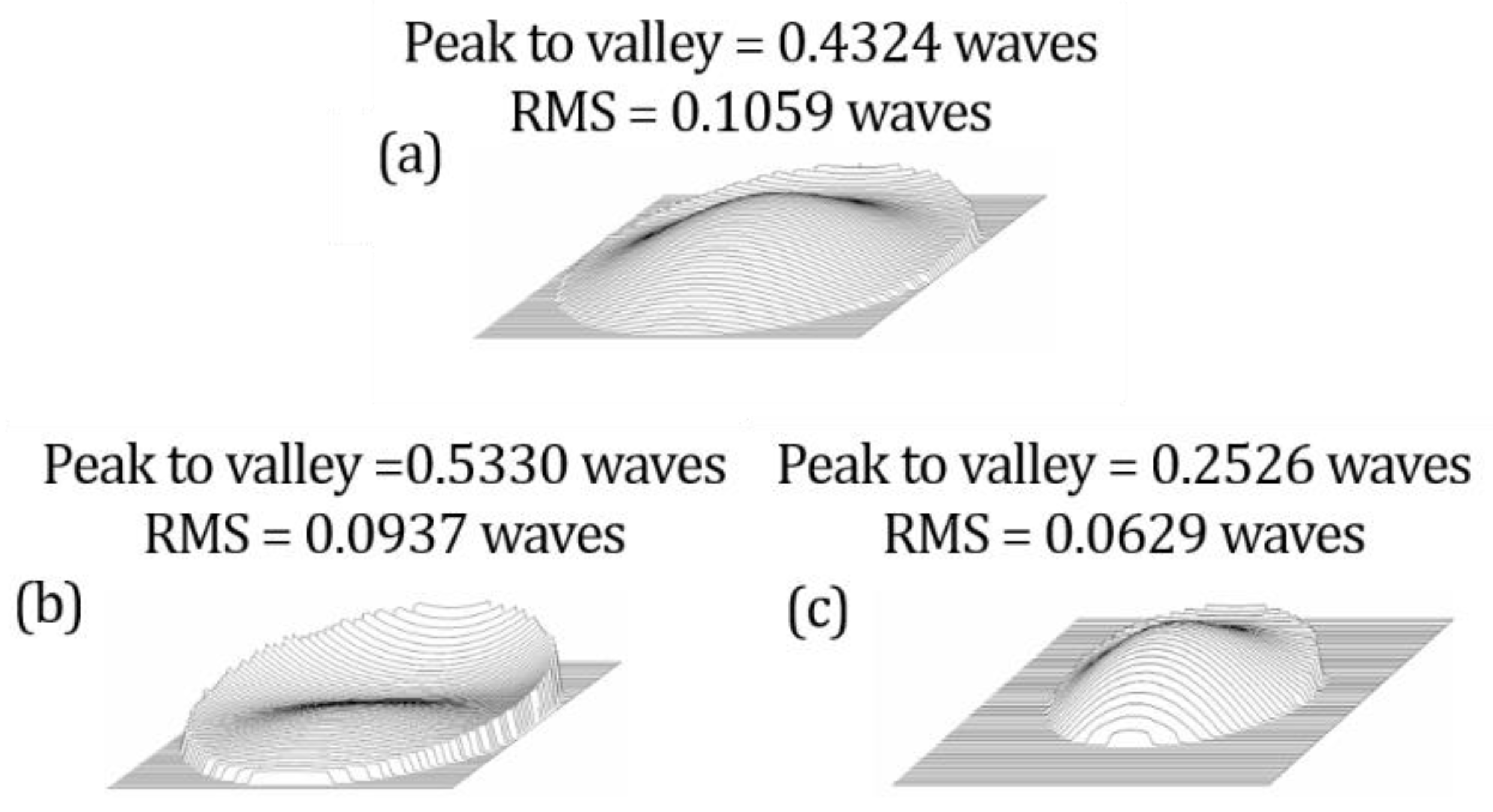
4.1. Inherent Aberration in the System

As mentioned before, an ideal lens with the aberration of eye instead of the eye structure was used to study the inherent aberration in the system. The pupil diameter of the eye was set to 4 mm. The spot sizes of the designed system in the vertical direction are shown in Figure 5. The spot diameter in the designed system does not change with the FOV in the horizontal direction. Figure 6 shows the variation curves of the spot diameter with the FOV according to the obtained data.
As showed in Figure 5 and Figure 6, in the vertical direction the spot size of the designed system increased with the FOV and stay within 20 μm within a 120-degree field of view. Due to the ellipsoidal imaging, the spot size in the horizontal direction remained constant (12.871 μm) as the FOV changed.
In the designed system, the spot size in the central region was approximately 12.871 μm. The main advantage of the designed system was that it could achieve an ultrawide field that could not be achieved by the conventional system; in addition, the inherent aberration in the designed system can be guaranteed to be relatively small for all FOVs. The Zernike standard coefficients and wavefront maps of the designed system in the central FOV and the edge FOVs (±55° in the vertical direction) are shown in Table 1 and Figure 7. The data in Table 1 indicate that defocus, 45° astigmatism and vertical coma were also the main aberrations in this system. During the design process, the defocus aberration in the central FOV was minimized. Therefore, the defocus values for the edge FOVs, especially the −55° FOV, were larger than those for the central FOV. In the central FOV, the resolution was affected mainly by the vertical coma, consistent with the imaging characteristics of the ellipsoidal mirror. The wavefront maps in Figure 7 intuitively show that the wavefronts in the edge FOVs were comparable to that in the central FOV in the designed system. This designed system sacrificed the resolution in the central FOV but increased the FOV by 57%.

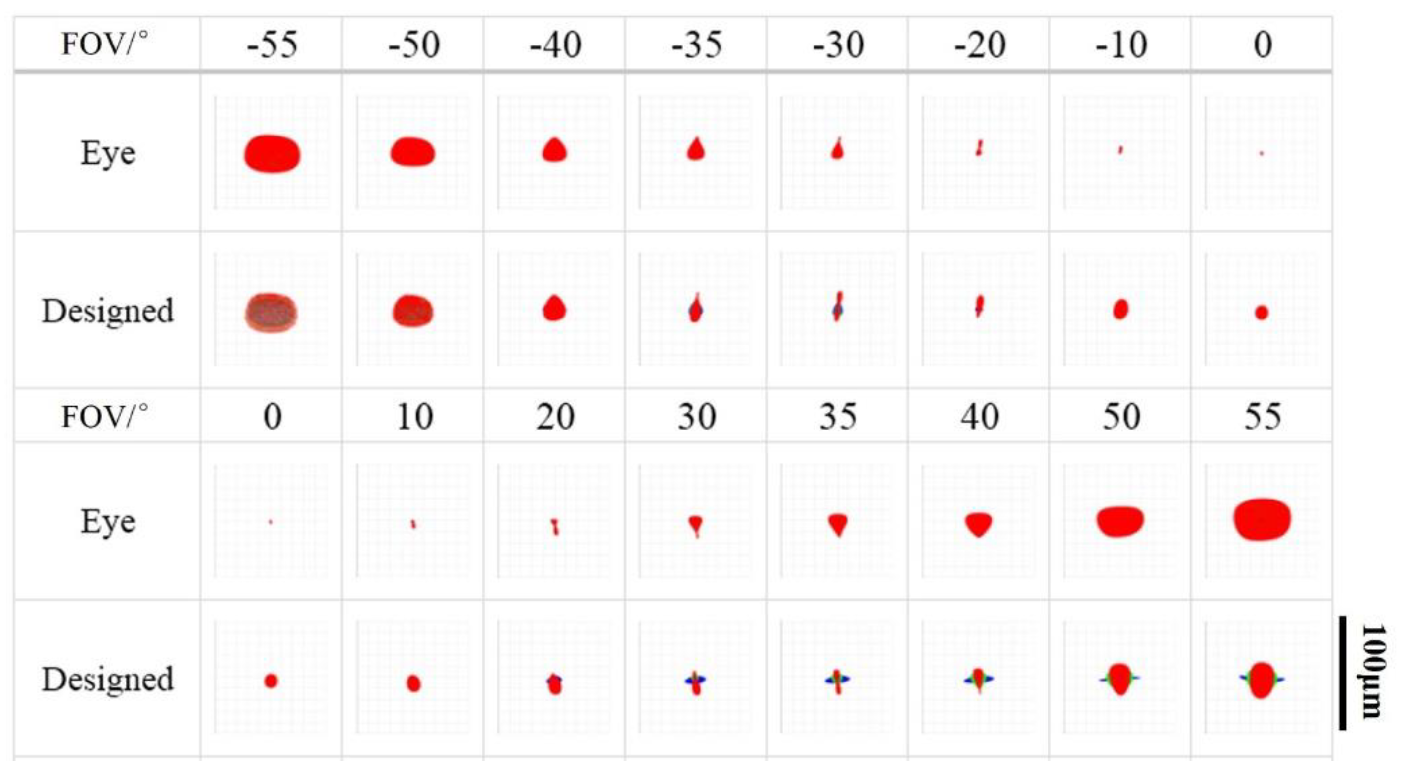
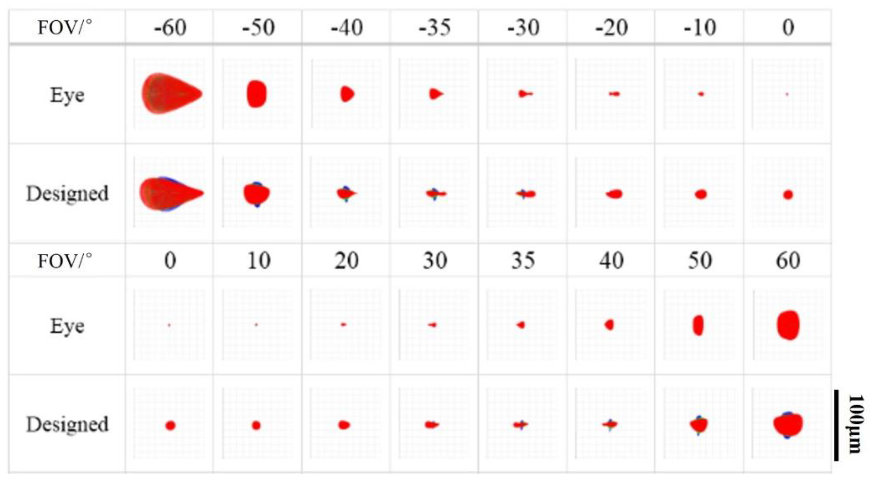
4.2. Aberrations in Retinal Imaging

The data in Figure 8 and Figure 9 show that the imaging FOV in the designed system was much larger than that in the conventional system. For larger FOVs (above ±30°), the aberrations in the eye increased. In the designed system, aberrations in the eye were the leading factor causing the deterioration in imaging quality. The scanning range of the designed system was as wide as ±100° in the horizontal direction, but the wavefront difference obtained from the eye model was only ±60°. Thus, the simulation could be carried out only over the range of ±60°.
Figure 10 presents the changes in the imaging quality with the designed system as the FOV changed. The focal spot size of the designed system in the wide FOV was almost the same as that of the eye itself. At −50° and +60°. Since the aberrations in the eye itself increased rapidly above ±50°, the imaging quality of the designed system was limited by the aberrations in the eye.
From the above results, it can be concluded that in the ultrawide field, the inherent aberration in the designed system was very small and that the final imaging quality was limited mainly by the aberrations in the eye. Here, a further analysis of the aberration for retinal imaging was performed. Considering the reliability of the data, the standard Zernike aberrations for retinal imaging at −40°, 0° and +40° in the vertical and horizontal directions are listed in Table 2 and Table 3. The aberrations for retinal imaging in the vertical direction and the horizontal direction were different from those of the designed system, not only because of the imaging characteristics of the designed system, but also because of the different aberrations in the eye in the two directions. In the central FOV, the main aberrations for retinal imaging were 45° astigmatism, horizontal coma, vertical coma and defocus, but all were relatively small. In the edge FOVs, astigmatism and coma aberration were the main aberrations in both the vertical and horizontal directions and were relatively large. This pattern was consistent with the results in other studies [17]. Due to the aberration characteristics of the eye, obtaining high-quality images in the ultrawide FOV directly was difficult. In addition, different aberrations were found in different eyes; thus, there were individual differences in the aberration correction.

5. Conclusions

In this paper, a design for an ultrawide field OCT retinal imaging scanning system was proposed and this system was simulated by optical design software Zemax. In addition, with the aberration of eye model, the quality of the retinal imaging by the designed system was presented and analyzed. The designed system could achieve ultrawide field retinal imaging (vertical: 110°, horizontal: 200°) unachievable by conventional systems. The working distance of the designed system is more than 30 mm, while that for the multi-lens systems that were reported for ultrawide range OCT imaging are only ranges of a few millimeters [10]. Compared to the multi-lens systems, the ellipsoidal mirror design maintains a relatively uniform spot size, especially at the large angle. Moreover, this system did not require pupil dilation. This work provided a new design for ultrawide field retinal imaging. It can provide structural information of peripheral retina for diseases such as retinal hyperplasia, retinal tear and detachment, retinal perforation, congenital retinal pigment epithelium hypertrophy, retinal capsular degeneration and retinal pigment degeneration. This ultrawide field retinal imaging design could expand possibilities for the diagnosis and treatment of retinopathy.

Supplementary Materials

The following are available online at https://www.mdpi.com/article/10.3390/photonics8110476/s1. Table S1: Input parameters of the designed ellipsoidal mirror scanning system for Zemax simulation.

Author Contributions

Conceptualization, S.L. and J.Z.; methodology, S.L., X.L. and J.K.; software, X.L., J.K. and J.W.; supervision, S.L. and J.Z.; validation, X.L., J.K. and M.W.; writing—original draft, S.L., J.K. and X.L.; review and editing, S.L. All authors have read and agreed to the published version of the manuscript.

Funding

This research was funded by National Natural Science Foundation of China (No. 61975246, 61505267) and Research Fund for Guangxi Distinguished Experts.

Conflicts of Interest

The authors declare no conflict of interest.

References

  1. Huang, D.; Swanson, E.A.; Lin, C.P.; Schuman, J.S.; Stinson, W.G.; Chang, W.; Hee, M.R.; Flotte, T.; Gregory, K.; Puliafito, C.A.; et al. Optical coherence tomography. Science 1991, 254, 1178–1181. [Google Scholar] [CrossRef] [PubMed] [Green Version]
  2. Drexler, W.; Fujimoto, J.G. Optical Coherence Tomography: Technology and Applications, 3rd ed.; Springer Science & Business Media: Berlin/Heidelberg, Germany, 2008. [Google Scholar]
  3. Yuichiro, K.; Muka, M.; Shuichiro, H.; Yuichiro, O.; Kyoko, O.M. Areas of nonperfusion in peripheral retina of eyes with pathologic myopia detected by ultra-widefield fluorescein angiography. Investig. Ophthalmol. Vis. Sci. 2014, 55, 1432–1439. [Google Scholar]
  4. Falavarjani, K.G.; Kang, W.; Khadamy, J.; Sadda, S.R. Ultra-wide-field imaging in diabetic retinopathy: An overview. J. Curr. Ophthalmol. 2016, 28, 57–60. [Google Scholar] [CrossRef] [PubMed] [Green Version]
  5. Ying, L.; Giovanni, G.; Lam, B.L.; Rosenfeld, P.J. Automatic montage of SD-OCT data sets. Opt. Express 2011, 19, 26239–26248. [Google Scholar]
  6. Mori, K.; Kanno, J.; Gehlbach, P.L.; Yoneya, S. Montage Images of Spectral-Domain Optical Coherence Tomography in Eyes with Idiopathic Macular Holes. Ophthalmology 2012, 119, 2600–2608. [Google Scholar] [CrossRef] [PubMed]
  7. Gregori, N.Z.; Lam, B.L.; Gregori, G.; Ranganathan, S.; Stone, E.M.; Morante, A.; Abukhalil, F.; Aroucha, P.R. Wide-Field Spectral-Domain Optical Coherence Tomography in Patients and Carriers of X-linked Retinoschisis. Ophthalmology 2013, 120, 169–174. [Google Scholar] [CrossRef] [PubMed] [Green Version]
  8. Choudhry, N.; Golding, J.; Manry, M.W.; Rao, R.C. Ultra-Widefield Steering-Based Spectral-Domain Optical Coherence Tomography Imaging of the Retinal Periphery. Ophthalmology 2016, 123, 1368–1374. [Google Scholar] [CrossRef] [PubMed]
  9. Klein, T.; Wieser, W.; Eigenwillig, C.M.; Biedermann, B.R.; Huber, R. Megahertz OCT for ultrawide-field retinal imaging with a 1050 nm Fourier domain mode-locked laser. Opt. Express 2011, 19, 3044–3062. [Google Scholar] [CrossRef] [PubMed]
  10. Kolb, J.P.; Klein, T.; Kufner, C.L.; Wieser, W.; Neubauer, A.S.; Huber, R. Ultra-widefield retinal MHz-OCT imaging with up to 100 degrees viewing angle. Biomed. Opt. Express 2015, 6, 1534–1552. [Google Scholar] [CrossRef] [PubMed] [Green Version]
  11. Polans, J.; Keller, B.; Carrascozevallos, O.M.; Larocca, F.; Cole, E.; Whitson, H.E.; Lad, E.M.; Farsiu, S.; Izatt, J.A. Wide-field retinal optical coherence tomography with wavefront sensorless adaptive optics for enhanced imaging of targeted regions. Biomed. Opt. Express 2017, 8, 16–37. [Google Scholar] [CrossRef] [PubMed] [Green Version]
  12. Brown, K.; Sewell, J.M.; Trempe, C.; Peto, T.; Travison, T.G. Comparison of image-assisted versus traditional fundus examination. Eye Brain 2013, 5, 1–8. [Google Scholar] [CrossRef] [PubMed] [Green Version]
  13. Witmer, M.T.; Kiss, S. Wide-field Imaging of the Retina. Surv. Ophthalmol. 2013, 58, 143–154. [Google Scholar] [CrossRef] [PubMed]
  14. Diabetic Retinopathy Clinical Research Network, Peripheral Diabetic Retinopathy (DR) Lesions on Ultrawide-Field Fundus Images and Risk of DR Worsening over Time. Available online: https://public.jaeb.org/drcrnet/stdy/239 (accessed on 1 January 2015).
  15. Mo, J.; de Groot, M.; de Boer, J.F. Focus-extension by depth-encoded synthetic aperture in Optical Coherence Tomography. Opt. Express 2013, 21, 10048–10061. [Google Scholar] [CrossRef] [PubMed] [Green Version]
  16. Polans, J.; Jaeken, B.; McNabb, R.P.; Artal, P.; Izatt, J.A. Wide-field optical model of the human eye with asymmetrically tilted and decentered lens that reproduces measured ocular aberrations. Optica 2015, 2, 124–134. [Google Scholar] [CrossRef] [Green Version]
  17. Jaeken, B.; Artal, P. Optical quality of emmetropic and myopic eyes in the periphery measured with high-angular resolution. Investig. Ophthalmol. Vis. Sci. 2012, 53, 3405–3413. [Google Scholar] [CrossRef] [PubMed] [Green Version]
Figure 1. Schematic illustrating the definition of the FOV for the point scanning OCT system.
Photonics 08 00476 g001
Figure 2. Configuration diagram of the SD OCT system. BLS: broadband light source, C: coupler, CL: collimator lens, DCE: dispersion compensation element, M: mirror, L: lens, OG: optical grating, D: detector, CP: computer.
Photonics 08 00476 g002
Figure 3. Design diagram of the sample arm.
Photonics 08 00476 g003
Figure 4. (a,c) The 3D layout of the designed ultrawide field system in the vertical and horizontal directions. (b,d) The shaded model in the vertical and horizontal directions. In the vertical shaded model, only beams in the central FOV are displayed to avoid occlusion.
Photonics 08 00476 g004
Figure 5. Spot sizes in the vertical direction when the eye is an ideal lens.
Photonics 08 00476 g005
Figure 6. Variation curves of the spot size with the FOV in the vertical and horizontal directions when the eye is an ideal lens.
Photonics 08 00476 g006
Figure 7. Wavefront maps at −55° (a), 0° (b) and +55° (c) in the designed system when the eye is an ideal lens.
Photonics 08 00476 g007
Figure 8. Spot sizes for retinal imaging in the vertical direction.
Photonics 08 00476 g008
Figure 9. Spot sizes for retinal imaging in the horizontal direction.
Photonics 08 00476 g009
Figure 10. Variation curves of the spot size for retinal imaging with changes in the FOV in the vertical and horizontal directions.
Photonics 08 00476 g010
Table 1. Zernike standard coefficients in the designed system.
OrderZernike Standard Coefficients/WavesAberration Meaning
−55°+55°
4−0.85054148−0.03969461−0.12081888Defocus
50.000000000.000000000.00000000Oblique astigmatism
6−0.02730028−0.00247943−0.0002089545° astigmatism
70.087048110.080299440.02916162Vertical coma
80.000000000.000000000.00000000Horizontal coma
9−0.00087236−0.00002330−0.00000153Tilted trefoil
100.000000000.000000000.00000000Horizontal trefoil
Table 2. Zernike standard coefficients for retinal imaging in the vertical direction.
OrderZernike Standard Coefficients/WavesAberration Meaning
−40°+40°
4−0.04778938−0.01478089−0.08433465Defocus
50.24196445−0.00512765−0.25042011Oblique astigmatism
6−1.32105706−0.04584397−1.3815243745° astigmatism
7−0.076607110.011200330.09391515Vertical coma
8−0.03552920−0.03162284−0.03574244Horizontal coma
9−0.087252830.000083560.09332905Tilted trefoil
10−0.01159125−0.00031933−0.01132933Horizontal trefoil
Table 3. Zernike standard coefficients of retinal imaging in the horizontal direction.
OrderZernike Standard Coefficients/WavesAberration Meaning
−40°+40°
4−0.10397192−0.01478089−0.12819229Defocus
5−0.02110464−0.005127650.00707697Oblique astigmatism
61.33305503−0.045843970.8315437645° astigmatism
70.013051380.011200330.01273088Vertical coma
8−0.08885472−0.031622840.06125572Horizontal coma
9−0.002589510.00008356−0.00220010Tilted trefoil
100.12015452−0.00031933−0.08867846Horizontal trefoil
Publisher’s Note: MDPI stays neutral with regard to jurisdictional claims in published maps and institutional affiliations.

