Communication

A Metasurface Beam Combiner Based on the Control of Angular Response

1
State Key Laboratory of Optoelectronic Materials and Technologies, School of Physics, Sun Yat-sen University, Guangzhou 510275, China
2
Southern Marine Science and Engineering Guangdong Laboratory (Zhuhai), Zhuhai 519080, China
*
Author to whom correspondence should be addressed.
Photonics 2021, 8(11), 489; https://doi.org/10.3390/photonics8110489
Submission received: 15 September 2021 / Revised: 20 October 2021 / Accepted: 29 October 2021 / Published: 2 November 2021
(This article belongs to the Special Issue Smart Pixels and Imaging)

Abstract

:
Beam combiners are widely used in various optical applications including optical communication and smart detection, which spatially overlap multiple input beams and integrate a output beam with higher intensity, multiple wavelengths, coherent phase, etc. Since conventional beam combiners consist of various optical components with different working principles depending on the properties of incident light, they are usually bulky and have certain restrictions on the incident light. In recent years, metasurfaces have received much attention and become a rapidly developing research field. Their novel mechanisms and flexible structural design provide a promising way to realize miniaturized and integrated components in optical systems. In this paper, we start from studying the ability of metasurfaces to manipulate the incident wavefront, and then propose a metasurface beam combiner in theory that generates an extraordinary refracted beam based on the principle of phase gradient metasurface. This metasurface combines two monochromatic light incidents at different angles with identical polarization but arbitrary amplitudes and initial phases. The combining efficiency, which is defined as the ratio of the power in the combining direction to the total incident power, is 42.4% at the working wavelength of 980 nm. The simulated results indicate that this proposed method is able to simplify the design of optical combiners, making them miniaturized and integrated for smart optical systems.

1. Introduction

Classic beam combining technologies, including polarization beam combining, wavelength beam combining and coherent beam combining, enable an amplification of the power of output light while ensuring good beam quality [1,2,3,4,5]. The first two beam combining technologies are classified as incoherent beam combining technologies, and their basic components are a polarizing beam splitter (BS) and dichroic BS, respectively. Both incoherent beam combiners can achieve 100% combining efficiency in theory, because they simply combine light of different incoherent properties, and the combining efficiency is only limited by the transmittance. However, the combined light still consists of independent waves. Coherent beam combining has attracted the most attention, since the outcome of combining coherent beams is more complicated due to interference. Researchers are making efforts to increase either the number of input ports [6,7], or the output power [8]. For example, the combination of more than 100 input beams has been achieved in fiber lasers [9]; more than 1000 watts of output power has been achieved by combining a small number of input beams [8,10]. The conventional coherent beam combiner proportionally combines the reflected light and the transmitted light illuminated from different sides of the lens at 45°, respectively. This mechanism makes the combination of coherent light inevitably lossy. Therefore, this beam combining scheme needs strict restrictions, e.g., the wavelength, polarization, amplitude, and initial phase, to achieve high combining efficiency. Moreover, the incident light must have fixed directions and angles, making conventional coherent beam combiners difficult to integrate into a compact optical system.
Metasurfaces are two-dimensional planar arrays composed of carefully designed optical resonators (meta-atoms) arranged at sub-wavelength resolution [11,12]. When the electromagnetic (EM) wave is transmitted through a metasurface, a distinct optical response occurs inside or around the meta-atoms [13] and brings abrupt changes to the optical properties (phase, amplitude, polarization) of the incident waves, which provides opportunities to engineer the output wavefront at will [14]. The capability of manipulating wavefronts on sub-wavelength scales gives them the possibility to perform various functions like conventional optical elements. Up to now, researchers have made metasurfaces not only as versatile components for imaging [15,16,17,18], sensing [19,20], holography [21,22], nonlinear processes [23,24], etc., but also as a tremendous platform for exploring marvelous functions which cannot be achieved by conventional optical devices [25,26,27,28].
Beam steering is one of the basic functions of the metasurfaces. Metasurface deflectors based on the generalized Snell’s law are able to deflect incoming EM waves to the desired direction by engineering an abrupt phase shift along the interface [29]. Researchers have proposed various metasurface deflectors for different applications. For example, using the wavelength-sensitive effect (i.e., chromatic dispersion) of the material, the dispersive phase of the metasurface deflector is designed to the required phase profile at different wavelengths [30]. By introducing the Pancharatnam–Berry phase (PB phase), which is a wavelength-independent phase, metasurfaces can achieve beam deflection over a broadband wavelength range [31,32]. Sub-wavelength structures with robust optical response at different incident angles (angle-insensitive) can be used for wide-angle range operation [33,34]. Apart from these, active materials, whose optical response can be dynamically regulated by external stimuli, can realize tunable beam deflection through a single metasurface [35,36,37]. Furthermore, beam splitting can be achieved when the metasurface deflects the input light into more than one output light at different angles [38,39].
It should be noted that normal beam deflection or splitting cannot achieve the function of a beam combiner [36,37,38,40,41]. Beam combining needs to create different responses for different incident conditions simultaneously. For example, Cheng et al. proposed a metagrating, which properly combines all the harmonics formed in the macroperiod of a set of unitcells, to combine two beams with the same polarization and wavelength in the reflection mode [42]. But its efficiency is only 35%. On the other hand, Wang et al. proposed a beam combiner based on the traveling-wave modulation in the metasurface, which reflects the scattered harmonics of the incident wave to the desired direction through frequency conversion with nearly 100% combining efficiency [43]. However, it cannot be used as a beam splitter at the same time, due to the nonreciprocity of this space-time metasurface.
In this paper, in order to combine and split beams by the same beam combiner, we adopt an angle-sensitive metasurface design to realize the beam combining and splitting in the transmission mode. As shown in Figure 1, the metasurface beam combiner composed of angle-sensitive meta-atoms can introduce distinct phase profiles designed for specific angles into each incident beam, so that the incident beams from different directions gain different deflection angles to have the same transmission direction. In this design, the input beams are on the same side of the metasurface, and the wavelength and polarization state are unchanged after beam combining. Meanwhile, the incident and diffraction angles of the light can be designed to be arbitrary values.

2. Design and Results

2.1. Gradient Metasurface for Beam Combining

In order to design the beam combiner with an unchanged polarization state, we decided to focus on the gradient metasurface. The gradient metasurface is used to bend the incident light to a desired direction. The relationship between the incident angle and the diffraction angle can be obtained by the generalized Snell’s law [29] written as follows:
n t s i n θ t n i s i n θ i = λ 0 2 π d φ d x ,
where n i and n t are the refractive indices of the surrounding medium on the incident and transmitted side, respectively. θ i and θ t denote the incident and diffraction angles. λ 0 is the vacuum wavelength of the EM wave. d φ / d x represents the phase gradient of the metasurface. If the number of unitcells in a single period is defined as N , then d φ equals to 2 π / N . d x is the unitcell’s length. By adjusting N and d x , a desired diffraction angle can be realized.
In order to deflect beams with different incident angles θ i 1 ,   θ i 2 ,   θ i 3   θ i n to the same diffraction angle θ t , the following equations should be fulfilled:
n t s i n θ t n i s i n θ i 1 = λ 0 2 π d φ i 1 d x n t s i n θ t n i s i n θ i 2 = λ 0 2 π d φ i 2 d x n t s i n θ t n i s i n θ i n = λ 0 2 π d φ i n d x
An illustration of beam combining using a gradient metasurface is shown in Figure 2. When working in single-port mode, the metasurface acts as a deflector and the output intensity I o u t is proportional to the deflection efficiency η i . When working in the multi-port mode, all input beams are deflected in the same direction and the output intensity is equal to the sum of the output intensity generated by each input port.
From Equation (2), we know that the maximum number of incident light beams depends on how many kinds of phase gradients (i.e., d φ i ) the metasurface can provide when excited from different incident angles. As a proof of concept, we designed a metasurface combiner that enables two beams with different incident angles to have the same diffraction direction. Therefore, an angle-sensitive unitcell is required in this design.

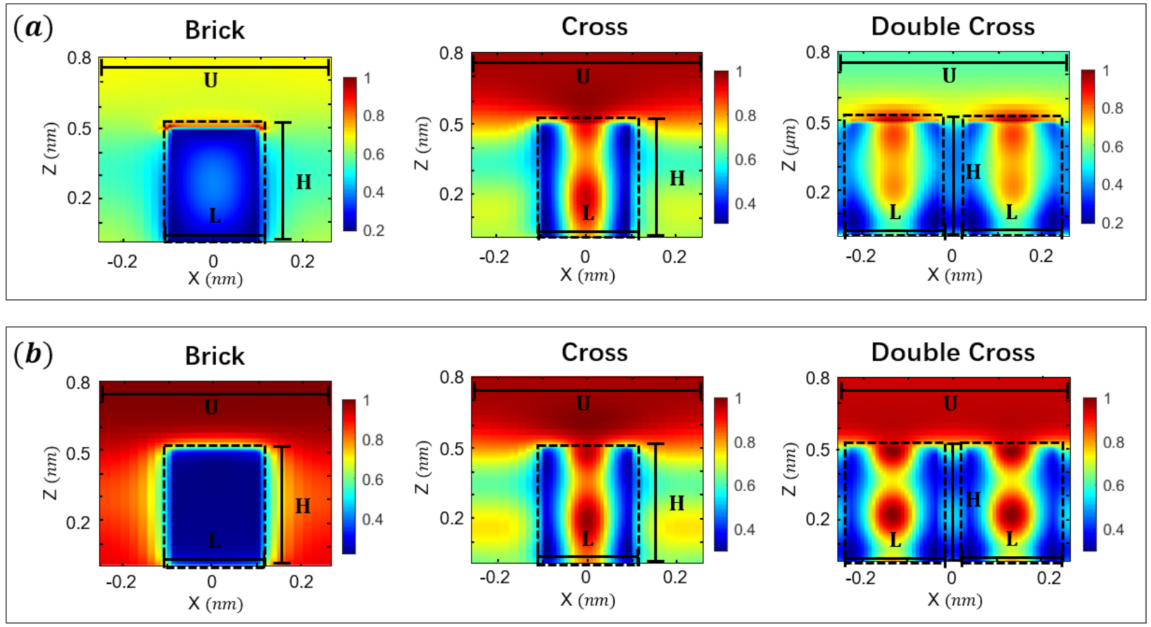
2.2. Angle-Sensitive Unitcell Design

Generally, most of the nano-structures do not show independent and distinct responses to various incident angles [44,45]. They will only go through a certain degree of distortion in the response characteristics, resulting in a decline in the overall efficiency of the device [46,47,48]. However, the distortion is not enough to realize independent wavefront control at different angles. In this paper, the energy coupling between adjacent nano-structures is skillfully utilized [49]. By precisely designing the size and arrangement of each nano-structure, the coupling effect between adjacent structures will change when light enters from different angles, resulting in significant phase changes and independent control of the incident light from different angles.
As mentioned before, most commonly used nano-structures have low sensitivity to the incident angle due to the relatively fixed energy distribution inside the structures when excited by an EM wave [26,33,34,44,45]. Considering that it is difficult for a single structure to have different resonant modes under different excitation angles, we adopted the unitcell design shown in Figure 3a. The substrate is glass, and two cross-shaped nano-pillars stand on the substrate. We employed crystalline silicon (c-Si) as the material, because its absorption at the working wavelength of 980 nm is negligible. The unitcell’s size (U) is set to be 520 nm in the entire design in order to manipulate the wavefront of the incident light (980 nm) in the sub-wavelength scale. When the metasurface transmits a y-polarized EM wave, the propagating mode is formed in each structure, and easily induces coupling between adjacent structures which varies with the incident angle. To prove the concept, we analyzed the resonance modes within the unitcells composed of nano-double-cross (Figure 3a), nano-cross (Figure 3b) and nano-brick (Figure 3c) structures. The length (L), width (W), height (H) are 189 nm, 86 nm, 500 nm, the unitcell’s size is 520 nm. Combining the calculated transmission phase (Figure 3d) and transmittance (Figure 3e), as well as the simulation results of the energy distribution of the electric field (Figure 4) on the cross section (the blue plane in Figure 3a–c) of each unitcell, it is shown that the energy distribution is different for the two incident angles of the same structure, which indicates that our designed structures are able to induce angular anisotropic response [50] and provide the widest range of phase variation among the three cases.
By adjusting the dimensions of the x-direction (L), y-direction (W) and z-direction (H), we built a phase library for the double cross structure. Considering the practical fabrication feasibility, the structure’s height (H) was set to 500 nm and the dimensions of L and W varied from 70–260 nm. Then the transmittance and transmission phase were calculated via finite-difference time-domain (FDTD) solver. Based on the results in Figure 3d,e, we found that the incident light at certain angles in the range of 0 ~ 15° can generate the required phases for the beam combining design. To improve the beam combining efficiency, we scanned the transmission phase in a smaller step size in the range of 0 ~ 15°. The results shown in Figure 5 indicate that the structures exhibit completely different phase responses at incident angles of −3.7° and 15°, which allows us to embed different phase gradients on a single metasurface to realize high-efficiency beam combining. As a comparison, we also calculated the transmission phase as the function of L and W for the single cross (Figure 3b) and brick (Figure 3c) structures; the results are given in Figure S1. Unlike the results in Figure 3 with small L value, we can see from Figure S1 that both of these structures have different phase responses at two incident angles when the value of the L is close to the size of the unitcell. In this situation, strong energy coupling occurs between adjacent unitcells. This will make the single cross and brick structures in every two unitcells similar to the double cross structures in one unitcell, which will bring phase changes when illuminated from different angles.

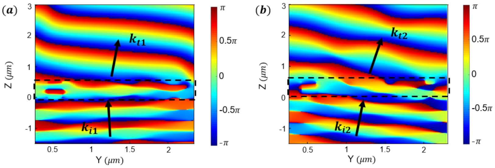
2.3. Metasurface Beam Combiner

According to Equation (2), the two incident angles should satisfy the following equation to have the same diffraction direction:
s i n θ i 2 s i n θ i 1 = λ 0 2 π n i d x d φ i 1 d φ i 2 .
In our design, the unitcell’s size d x equals 520 nm, the operating wavelength λ 0 is 980 nm, the incident medium is glass n i = 1.46 and the transmitted medium is air   n t 1 . We choose four structures in a 2 π —phase deflective period; therefore, its phase gradient is either 2 π / 4 or 0 . As shown in Figure 6, the four unitcells arranged along the y-axis represent a single period (a supercell) with a length of 2080 nm. We periodically repeat this configuration along the horizontal and vertical directions to provide two different phase profiles. When light is incident at an angle of θ i 1 , the metasurface will impart an extra momentum Δ k 1 to the incident wavevector, leading to an abnormal refraction which can be described by Equation (1). The diffraction angle and wavevector are noted as θ t and k t , respectively. When it enters from θ i 2 , the phase gradient on the metasurface turns to zero. Thus, a normal refraction occurs, and a transmitted light beam with the same diffraction angle θ t is generated. Specifically, when we choose incident angles of −3.7° and 15° (Figure 5), the unique diffraction angle θ t will be 22.2°.
The parameters of the four unitcells we used in this design are given in Figure 6c. During the design process, we noticed that the transmission phase of the unitcell after being arranged in the metasurface combiner becomes slightly different from that in the phase library. The main reason is that, in some cases, energy coupling not only occurs between adjacent structures, but also between adjacent unitcells. Therefore, the boundary conditions of these unitcells in the metasurface combiner simulation process are different from those in the transmission phase scanning process. Based on this, we allow more phase errors in the selection process to get more alternative unitcells, and then we choose the unitcells which have weaker coupling between adjacent unitcells, or the unitcells which have the required phases despite the coupling. Because of this reason, to avoid stronger energy coupling between the unitcells in the single cross or brick structures, we use the double cross structures to design the beam combiner.
To verify our design, we performed simulations in the FDTD solver. In the simulation setup, the light beam is incident from the glass substrate, and is transmitted into the air at a desired deflection angle after propagating through the metasurface.
The phase profiles of plane waves propagating through the metasurface combiner at incident angles of −3.7° and 15° are shown in Figure 7a,b, respectively. The results demonstrate that the two incident light beams with different incident angles are deflected to the same direction after propagating through the metasurface.
We further investigated the far-field intensity of the two incident beams. As shown in Figure 8a,b, the two incident light beams enter from the substrate side after propagating through the metasurface; most of the power will reach the desired diffraction order and be successfully combined. Specifically, in Figure 8a, the incident light beam of −3.7° is diffracted to an angle of 22.2°, and the diffraction efficiency (defined as the ratio of power in the desired diffraction order to the total transmitted power) and the transmission efficiency are 68.15% and 64.76%, respectively. Hence the deflection efficiency [25,51] is 44.13%. In Figure 8b, the incident light beam of 15° is also refracted to an angle of 22.2°. The diffraction efficiency, transmission efficiency and deflection efficiency are 73.99%, 54.97% and 40.67%, respectively. Thus, the combining efficiency of our metasurface combiner is 42.4%. Here, we assume that the input power of the incident light at two angles is equal. In addition, we declared that our metasurface combiner could also work as a beam splitter when illuminated from the other side. In Figure 8c, a 22.2° incident light beam enters from the structure side, it will split into two transmitted beams with the angles of −15° and 3.7°. Here, the transmission efficiency is 91% and the split ratio is approximately 1:1.14.
We also simulated the performance of our metasurface with different incident polarization states in Figure S2. The cross structures have the same length in both the x-direction and the y-direction, hence the metasurface also works in other incident polarization states. Meanwhile, the efficiencies for beam combining and splitting decrease nearly 10% when the polarization angle changes from 0° (y-polarized) to 90° (x-polarized), which is because the coupling mode between each structure changes when excited by x-polarized light.

3. Discussion

Compared with conventional coherent beam combining technology, our metasurface beam combiner has no restriction on the phase and amplitude of the incident beams, and the unchanged polarization and wavelength make sure the output light could continue to be combined any number of times. Besides, in our design, the combining efficiency is close to the upper limit (50% of the total input power) of the BS. The performance of this metasurface beam combiner can be further improved by optimizing the coupling modes between unitcells and shrinking the size of unitcells, thereby reducing the grating period [51,52].
Moreover, we found that in the range of 0 ~ 15°, this metasurface could satisfy more than two kinds of phase gradients when illuminated at certain angles, which suggested that it has the potential to combine three or more incident beams with different angles into the same direction. A phase library with more meta-atoms, larger angle range, and finer scanning results will be necessary to find more ports with higher efficiency. It is worth pointing out that, in coherent beam combining, the efficiency of power from one input port coupled to the output port depends on the changes in the coherent condition of the input beam number N [43]. In contrast, our metasurface combiner maintains the same efficiency regardless of the input beam number N, since each port works independently. This will be a potential advantage compared to conventional coherent beam combining, if a large number of beams are to be combined.
However, we found that the current device is still influenced by the optical memory effect [44,50]. The optical responses at a certain angle will appear at another angle, which makes independent control worse and inefficient. In the future, we expect to alleviate the mutual interference between incident light from different angles through better unitcell design, in order that a metasurface combiner that allows more input beams can be readily achieved.

4. Conclusions

Deflecting is one of the basic functions of metasurfaces and has been achieved by various methods. For example, metagrating can give back the best deflection efficiency [53], and metasurfaces built by angle-insensitive sub-wavelength meta-atoms can be used for wide-angle range operation [33,34]. However, normal beam deflectors or splitters cannot achieve the function of beam combining [36,37,38,40,41]. Hence, in this work, we designed a metasurface beam combiner based on double cross structures, which provide an angle-sensitive optical response. As a proof of concept, we successfully demonstrated a metasurface combiner working in transmission mode. The simulation results indicated that two beams with identical wavelength and polarization but different incident angles could be combined into the same scattering direction. The combining efficiency of our metasurface combiner is 42.4%, which is very close to commercial BS devices. It can also act as a beam splitter when illuminated from the other side. The splitting ratio is 1:1.14, and the splitting efficiency is 88.1%. We believe that the proposed design provides a flexible way to realize beam combining and splitting.

Supplementary Materials

The following are available online at https://www.mdpi.com/article/10.3390/photonics8110489/s1, Figure S1: Transmission phase map of the single cross structures (a–c) and brick structures (d–f), Figure S2: Deflection efficiency for different incident conditions.

Author Contributions

J.L. and Z.L. conceived the idea. Z.L. contributed the structure design and numerical simulations. Z.L., H.L. and X.F. wrote the manuscript with input from all authors. J.L., X.F. and Z.Q. supervised the project. All authors analyzed the data and discussed the results. All authors have read and agreed to the published version of the manuscript.

Funding

This research is funded by the Guangdong Provincial Key R&D Program (No. 2019B010152001); National Natural Science Foundation of China (Nos. 11974436, 12074444); Guangdong Basic and Applied Basic Research Foundation (Nos. 2020B1515020019, 2020A1515011184); and Guangzhou Basic and Applied Basic Research Foundation (No. 202102020987). H.L. acknowledges support by Innovation Group Project of Southern Marine Science and Engineering Guangdong.

Institutional Review Board Statement

Not applicable.

Informed Consent Statement

Not applicable.

Data Availability Statement

Data is contained within the article and the Supplementary Materials.

Conflicts of Interest

The authors declare no conflict of interest.

References

  1. Daneu, V.; Sanchez, A.; Fan, T.Y.; Choi, H.K.; Turner, G.W.; Cook, C.C. Spectral beam combining of a broad-stripe diode laser array in an external cavity. Opt. Lett. 2000, 25, 405–407. [Google Scholar] [CrossRef] [PubMed]
  2. Augst, S.J.; Ranka, J.K.; Fan, T.Y.; Sanchez, A. Beam combining of ytterbium fiber amplifiers (Invited). J. Opt. Soc. Am. B 2007, 24, 1707–1715. [Google Scholar] [CrossRef]
  3. Jin, Y.Y.; Zou, Y.G.; Ma, X.H.; Li, J.; Li, Y.; Jin, L.; Xu, L.; Zhao, W.; Sui, Q.X.; Zhang, Z.W. Study on laser diode incoherent beam combining technology based on tracepro. In Proceedings of the International Conference on Optoelectronics & Microelectronics (ICOM), Changchun, China, 23–25 August 2012; pp. 87–90. [Google Scholar]
  4. Fan, T.Y. Laser beam combining for high-power, high-radiance sources. IEEE J. Sel. Top. Quantum Electron. 2005, 11, 567–577. [Google Scholar] [CrossRef]
  5. Zhou, P.; Liu, Z.J.; Wang, X.L.; Ma, Y.X.; Ma, H.T.; Xu, X.J. Coherent beam combination of two-dimensional high-power fiber amplifier array using stochastic parallel gradient descent algorithm. Appl. Phys. Lett. 2009, 94, 231106. [Google Scholar] [CrossRef]
  6. Bourderionnet, J.; Bellanger, C.; Primot, J.; Brignon, A. Collective coherent phase combining of 64 fibers. Opt. Express 2011, 19, 17053–17058. [Google Scholar] [CrossRef] [PubMed]
  7. Su, R.T.; Xi, J.C.; Chang, H.X.; Ma, Y.X.; Ma, P.F.; Wu, J.; Jiang, M.; Zhou, P.; Si, L.; Xu, X.J.; et al. Coherent combining of 60 fiber lasers using stochastic parallel gradient descent algorithm. In Proceedings of the Applications of Lasers for Sensing and Free Space Communications, Vienna, Austria, 29 September–3 October 2019; p. JW2A-1. [Google Scholar] [CrossRef]
  8. Yu, C.X.; Augst, S.J.; Redmond, S.M.; Goldizen, K.C.; Murphy, D.V.; Sanchez, A.; Fa, T.Y. Coherent combining of a 4 kW, eight-element fiber amplifier array. Opt. Lett. 2011, 36, 2686–2688. [Google Scholar] [CrossRef] [PubMed]
  9. Chang, H.X.; Chang, Q.; Xi, J.C.; Hou, T.Y.; Su, R.T.; Ma, P.F.; Wu, J.; Li, C.; Jiang, M.; Ma, Y.X.; et al. First experimental demonstration of coherent beam combining of more than 100 beams. Photonics Res. 2020, 8, 1943–1948. [Google Scholar] [CrossRef]
  10. Flores, A.; Ehrenreich, T.; Holten, R.; Anderson, B.; Dajani, I. Multi-kW coherent combining of fiber lasers seeded with pseudo random phase modulated light. Proc. SPIE 2016, 9728, 97281Y. [Google Scholar]
  11. Lin, D.M.; Fan, P.Y.; Hasman, E.; Brongersma, M.L. Dielectric gradient metasurface optical elements. Science 2014, 345, 298–302. [Google Scholar] [CrossRef]
  12. Lio, G.E.; Ferraro, A.; Ritacco, T.; Aceti, D.M.; De Luca, A.; Giocondo, M.; Caputo, R. Leveraging on ENZ Metamaterials to Achieve 2D and 3D Hyper-Resolution in Two-Photon Direct Laser Writing. Adv. Mater. 2021, 33, 2008644. [Google Scholar] [CrossRef]
  13. Sun, Q.; Liang, H.W.; Zhang, J.C.; Feng, W.B.; Martins, E.R.; Krauss, T.F.; Li, J.T. Highly efficient air-mode silicon metasurfaces for visible light operation embedded in a protective silica layer. Adv. Opt. Mater. 2021, 9, 2002209. [Google Scholar] [CrossRef]
  14. Yu, N.F.; Capasso, F. Flat optics with designer metasurfaces. Nat. Mater. 2014, 13, 139–150. [Google Scholar] [CrossRef]
  15. Khorasaninejad, M.; Chen, W.T.; Devlin, R.C.; Oh, J.; Zhu, A.Y.; Capasso, F. Metalenses at visible wavelengths: Diffraction-limited focusing and subwavelength resolution imaging. Science 2016, 352, 1190–1194. [Google Scholar] [CrossRef] [Green Version]
  16. Chen, B.H.; Wu, P.C.; Su, V.C.; Lai, Y.C.; Chu, C.H.; Lee, I.C.; Chen, J.W.; Chen, Y.H.; Lan, Y.C.; Kuan, C.H.; et al. GaN metalens for pixel-level full-color routing at visible light. Nano Lett. 2017, 17, 6345–6352. [Google Scholar] [CrossRef]
  17. Avayu, O.; Almeida, E.; Prior, Y.; Ellenbogen, T. Composite functional metasurfaces for multispectral achromatic optics. Nat. Commun. 2017, 8, 14992. [Google Scholar] [CrossRef] [PubMed]
  18. Arbabi, A.; Arbabi, E.; Kamali, S.M.; Horie, Y.; Han, S.; Faraon, A. Miniature optical planar camera based on a wide-angle metasurface doublet corrected for monochromatic aberrations. Nat. Commun. 2016, 7, 13682. [Google Scholar] [CrossRef] [PubMed]
  19. Islam, M.S.; Sultana, J.; Biabanifard, M.; Vafapour, Z.; Nine, M.J.; Dinovitser, A.; Cordeiro, C.M.B.; Ng, B.W.H.; Abbott, D. Tunable localized surface plasmon graphene metasurface for multiband superabsorption and terahertz sensing. Carbon 2020, 158, 559–567. [Google Scholar] [CrossRef]
  20. Rodrigo, D.; Limaj, O.; Janner, D.; Etezadi, D.; de Abajo, F.J.G.; Pruneri, V.; Altug, H. Mid-infrared plasmonic biosensing with graphene. Science 2015, 349, 165–168. [Google Scholar] [CrossRef] [PubMed] [Green Version]
  21. Zheng, G.X.; Muhlenbernd, H.; Kenney, M.; Li, G.X.; Zentgraf, T.; Zhang, S. Metasurface holograms reaching 80% efficiency. Nat. Nanotechnol. 2015, 10, 308–312. [Google Scholar] [CrossRef] [PubMed]
  22. Burch, J.; Wen, D.D.; Chen, X.Z.; Di Falco, A. Conformable holographic metasurfaces. Sci. Rep. 2017, 7, 4520. [Google Scholar] [CrossRef] [Green Version]
  23. Yang, Y.M.; Wang, W.Y.; Boulesbaa, A.; Kravchenko, I.I.; Briggs, D.P.; Puretzky, A.; Geohegan, D.; Valentine, J. Nonlinear fano-resonant dielectric metasurfaces. Nano Lett. 2015, 15, 7388–7393. [Google Scholar] [CrossRef] [PubMed]
  24. Chervinskii, S.; Koskinen, K.; Scherbak, S.; Kauranen, M.; Lipovskii, A. Nonresonant local fields enhance second-harmonic generation from metal nanoislands with dielectric cover. Phys. Rev. Lett. 2018, 120, 113902. [Google Scholar] [CrossRef] [PubMed] [Green Version]
  25. Zhou, Z.P.; Li, J.T.; Su, R.B.; Yao, B.M.; Fang, H.L.; Li, K.Z.; Zhou, L.D.; Liu, J.; Stellinga, D.; Reardon, C.P.; et al. Efficient silicon metasurfaces for visible light. ACS Photonics 2017, 4, 544–551. [Google Scholar] [CrossRef]
  26. Martins, A.; Li, K.Z.; Li, J.T.; Liang, H.W.; Conteduca, D.; Borges, B.V.; Krauss, T.F.; Martins, E.R. On metalenses with arbitrarily wide field of view. ACS Photonics 2020, 7, 2073–2079. [Google Scholar] [CrossRef]
  27. Chen, K.; Ding, G.W.; Hu, G.W.; Jin, Z.W.; Zhao, J.M.; Feng, Y.J.; Jiang, T.; Alu, A.; Qiu, C.W. Directional janus metasurface. Adv. Mater. 2020, 32, 1906352. [Google Scholar] [CrossRef] [PubMed]
  28. Devlin, R.C.; Ambrosio, A.; Rubin, N.A.; Mueller, J.P.B.; Capasso, F. Arbitrary spin-to-orbital angular momentum conversion of light. Science 2017, 358, 896–900. [Google Scholar] [CrossRef] [Green Version]
  29. Yu, N.F.; Genevet, P.; Kats, M.A.; Aieta, F.; Tetienne, J.P.; Capasso, F.; Gaburro, Z. Light propagation with phase discontinuities: Generalized laws of reflection and refraction. Science 2011, 334, 333–337. [Google Scholar] [CrossRef] [Green Version]
  30. Aieta, F.; Kats, M.A.; Genevet, P.; Cappasso, F. Multiwavelength achromatic metasurfaces by dispersive phase compensation. Science 2015, 347, 1342–1345. [Google Scholar] [CrossRef]
  31. Zhang, X.Q.; Tian, Z.; Yue, W.S.; Gu, J.Q.; Zhang, S.; Han, J.G.; Zhang, W.L. Broadband terahertz wave deflection based on C-shape complex metamaterials with phase discontinuities. Adv. Mater. 2013, 25, 4567–4572. [Google Scholar] [CrossRef]
  32. Yang, H.; Deng, Y. Broadband and high efficiency all-dielectric metasurfaces for wavefront steering with easily obtained phase shift. Opt. Commun. 2017, 405, 39–42. [Google Scholar] [CrossRef]
  33. Zhao, Y.; Alu, A. Manipulating light polarization with ultrathin plasmonic metasurfaces. Phys. Rev. B 2011, 84, 205428. [Google Scholar] [CrossRef]
  34. He, M.X.; Guo, Y.H.; Li, C.S.; Tong, X.; Liu, H.A.; Li, G.F.; Zhang, L. Metasurface-based wide-angle beam steering for optical trapping. IEEE Access 2020, 8, 37275–37280. [Google Scholar] [CrossRef]
  35. Komar, A.; Paniagua-Dominguez, R.; Miroshnichenko, A.; Yu, Y.F.; Kivshar, Y.S.; Kuznetsov, A.I.; Neshev, D. Dynamic beam switching by liquid crystal tunable dielectric metasurface. ACS Photonics 2018, 5, 1742–1748. [Google Scholar] [CrossRef] [Green Version]
  36. Lio, G.E.; Ferraro, A. LIDAR and beam steering tailored by neuromorphic metasurface dipped in a tunable surrounding medium. Photonics 2021, 8, 65. [Google Scholar] [CrossRef]
  37. Shirmanesh, G.K.; Sokhoyan, R.; Wu, P.C.; Atwater, H.A. Electro-optically tunable multifunctional metasurface. ACS Nano 2020, 14, 6912–6920. [Google Scholar] [CrossRef] [PubMed]
  38. Albero, J.; Davis, J.A.; Cottrell, D.M.; Granger, C.E.; McCormick, K.R.; Moreno, I. Generalized diffractive optical elements with asymmetric harmonic response and phase control. Appl. Opt. 2013, 52, 3637–3644. [Google Scholar] [CrossRef] [Green Version]
  39. Yang, J.J.; Sell, D.; Fan, J.A. Freeform metagratings based on complex light scattering dynamic for extreme, high efficiency beam steering. Ann. Der. Phys. 2018, 530, 1700302. [Google Scholar] [CrossRef] [Green Version]
  40. Chen, X.Y.; Zou, H.J.; Su, M.Y.; Tang, L.W.; Wang, C.F.; Chen, S.Q.; Su, C.L.; Li, Y. All-dielectric metasurface-based beam splitter with arbitrary splitting ratio. Nanomaterials 2021, 11, 1137. [Google Scholar] [CrossRef]
  41. Li, J.; Ye, H.; Wu, T.S.; Liu, Y.M.; Yu, Z.Y.; Wang, Y.; Sun, Y.H.; Yu, L. Ultra-broadband large-angle beam splitter based on a homogeneous metasurface at visible wavelengths. Opt. Express 2020, 28, 32226–32238. [Google Scholar] [CrossRef]
  42. Cheng, J.R.; Inampudi, S.; Mosallaei, H. Optimization-based dielectric metasurfaces for angle-selective multifunctional beam deflection. Sci. Rep. 2017, 7, 12228. [Google Scholar] [CrossRef] [Green Version]
  43. Wang, X.; Asadchy, V.S.; Fan, S.; Tretyakov, S.A. Space-time metasurfaces for perfect power combining of waves. arXiv 2021, arXiv:2105.14627vl. [Google Scholar]
  44. Kamali, S.M.; Arbabi, A.; Arbabi, E.; Horie, Y.; Faraon, A. Decoupling optical function and geometrical form using conformal flexible dielectric metasurfaces. Nat. Commun. 2016, 7, 11618. [Google Scholar] [CrossRef] [PubMed] [Green Version]
  45. Jang, M.; Horie, Y.; Shibukawa, A.; Brake, J.; Liu, Y.; Kamali, S.M.; Arbabi, A.; Ruan, H.W.; Faraon, A.; Yang, C.H. Wavefront shaping with disorder-engineered metasurfaces. Nat. Photonics 2018, 12, 84–90. [Google Scholar] [CrossRef]
  46. Decker, M.; Chen, W.T.; Nobis, T.; Zhu, A.Y.; Khorasaninejad, M.; Bharwani, Z.; Capasso, F.; Petschulat, J. Imaging performance of polarization-insensitive metalenses. ACS Photonics 2019, 6, 1493–1499. [Google Scholar] [CrossRef]
  47. Kalvach, A.; Szabo, Z. Aberration-free flat lens design for a wide range of incident angles. J. Opt. Soc. Am. B 2016, 33, A66–A71. [Google Scholar] [CrossRef]
  48. Jiang, Z.H.; Lin, L.; Ma, D.; Yun, S.; Werner, D.H.; Liu, Z.W.; Mayer, T.S. Broadband and wide field-of-view plasmonic metasurface-enabled waveplates. Sci. Rep. 2014, 4, 7511. [Google Scholar] [CrossRef] [PubMed]
  49. Zhang, X.Y.; Li, Q.; Liu, F.F.; Qiu, M.; Sun, S.L.; He, Q.; Zhou, L. Controlling angular dispersions in optical metasurfaces. Light Sci. Appl. 2020, 9, 76. [Google Scholar] [CrossRef] [PubMed]
  50. Kamali, S.M.; Arbabi, E.; Arbabi, A.; Horie, Y.; Faraji-Dana, M.; Faraon, A. Angle-multiplexed metasurfaces: Encoding independent wavefronts in a single metasurface under different illumination angles. Phys. Rev. X 2017, 7, 041056. [Google Scholar] [CrossRef] [Green Version]
  51. Aoni, R.A.; Rahmani, M.; Xu, L.; Kamali, K.Z.; Komar, A.; Yen, J.S.; Neshev, D.; Miroshnichenko, A.E. High-efficiency visible light manipulation using dielectric metasurface. Sci. Rep. 2019, 9, 6510. [Google Scholar] [CrossRef] [PubMed] [Green Version]
  52. Asadchy, V.S.; Diaz-Rubio, A.; Tcvetkova, S.N.; Kwon, D.H.; Elsakka, A.; Albooyeh, M.; Tretyakov, S.A. Flat engineered multichannel reflectors. Phys. Rev. X 2017, 7, 031046. [Google Scholar] [CrossRef]
  53. Snell, D.; Yang, J.J.; Doshay, S.; Yang, R.; Fan, J.A. Large-angle, multifunctional metagrating based on freeform multimode geometries. Nano Lett. 2017, 17, 3752–3757. [Google Scholar]
Figure 1. Schematic depiction of our metasurface combiner. Two incident beams will be bent to the same diffraction angle after propagating through the metasurface. The incident angles are −3.7° and 15°, respectively. The diffraction angle is 22.2°.
Photonics 08 00489 g001
Figure 2. Schematic of the metasurface beam combiner. (a) Working in single-port mode; (b) Working in multi-port mode.
Photonics 08 00489 g002
Figure 3. (ac) Three kinds of unitcells, the dimension (L, W, H, U) of the structures here are L = 189 nm, W = 86 nm, H = 500 nm, U = 520 nm; (d,e) The transmission phase and transmittance of the three different nano-structures.
Photonics 08 00489 g003
Figure 4. Energy distribution of the electric field on the cross section of the three unitcells. The colorbars represent the intensity of the electric field at different positions, and the intensity is normalized to the maximum intensity in each graph. (a) 15° incident light; (b) 0° incident light. The dimensions (L, H, U) of the structures here are L = 189 nm, H = 500 nm, U = 520 nm.
Photonics 08 00489 g004
Figure 5. Transmission phase map of the double cross structures: (a) −3.7° incident light; (b) 15° incident light; (c) The phase difference between (a) and (b). The unitcell’s size is 520 nm, the structure height (H) is 500 nm, the length (L) and the width (W) vary from 70–260 nm.
Photonics 08 00489 g005
Figure 6. Working principle of the metasurface combiner under different incident angles. Four unitcells compose a supercell (a single period of the gradient metasurface) to deflect the incident beam. The length of the supercell is 2080 nm. (a) Light goes through an abnormal refraction; (b) Light goes through normal refraction; (c) The four unitcells we used in the metasurface combiner design.
Photonics 08 00489 g006
Figure 7. Simulation results of the metasurface combiner. (a) Phase profile of −3.7° incident light enters from the substrate side of the metasurface. (b) Phase profile of 15° incident light enters from the substrate side of the metasurface.
Photonics 08 00489 g007
Figure 8. The far-field intensity for the three incident conditions with (a) −3.7° incident angle. (b) 15° incident angle. (c) 22.2° incident angle. The far-field intensity is normalized to the total intensity of the input light. (a) and (b) represent the beam combining, (c) represents the beam splitting.
Photonics 08 00489 g008aPhotonics 08 00489 g008b
Publisher’s Note: MDPI stays neutral with regard to jurisdictional claims in published maps and institutional affiliations.

