1. Introduction
For the first time, vector singularities as a generalization of scalar singularities were proposed in 1983 by J.F. Nye [
1], where lines of zero-valued transverse components of the E-field were called ‘disclinations’ (to distinguish them from scalar edge and screw dislocations [
2]). However, both in Refs. [
1,
2] and in Ref. [
3], the polarization singularities were studied locally, i.e., in a neighborhood of singular (critical) points. It would be of significant interest to investigate globally inhomogeneously polarized light fields characterized by different (linear, elliptical, or circular) polarizations at different points of the beam cross-section. That is, we aim to determine topological charges and singularity indices of the whole light field. Such studies become relevant due to a growing number of publications concerned with inhomogeneously polarized vector fields [
4]. Inhomogeneously polarized beams can be generated by interferometry [
5] or inside a cavity [
6], as well as with q-plates [
7], metasurfaces [
8,
9], polarization prisms [
10], and spatial light modulators [
11]. Points of intensity nulls at which the linear polarization vector is not defined are called V-points [
3]. In a similar way, points of a light field with inhomogeneous elliptical polarization where the direction of the major axis of the polarization ellipse is undefined are called ‘C-points’, with the light being circularly polarized at such points. If the C-points are arranged on a line, the line is called a C-line [
3]. Polarization singularities are described by singularity indices, which are calculated similarly to the topological charges of scalar light fields [
12]. The polarization singularity index of V-points is called a Poincare–Hopf index [
3] and calculated using Stokes parameters [
13,
14,
15]. Meanwhile, the C-points are described by an index equal to the number of turns by
π that the major axis of the polarization ellipse makes around the C-point. The index of a C-point can take a fractional (half-integer) value if, on a complete turn, the polarization ellipse makes an odd number of turns by
π. When intersecting C-lines, the polarization ellipse axis makes a jump by
π/2.
In this work, we look into a hybrid
nth order vector light field whose polarization varies from linear to elliptical, to circular, depending on the polar angle. This field contains just C-lines with their number being equal to
n. For this field, we find components of the Stokes vector and show the polarization index to be a half-integer,
n/2. Using a Richards–Wolf formalism [
16], we derive analytical expressions for projections of the E-vector at the tight focus for a source hybrid
nth order vector field and analytical relations for the field intensity at the focus. We find that at an even number
n, the intensity has
nth order symmetry and C-points at the focus. Thus, we numerically demonstrate that C-lines in the source field ‘disintegrate’ into C-points at the focus, which are located on the same C-lines. We also derive analytical relationships for the projection of the Stokes vector at the focus, which suggest that for an odd number
n, the field at the focus is purely vectorial, consists of vectors of linear polarization, has
n V-points, and has no C-points.
2. Source Hybrid Vector Field with Polarization Singularity Points
Let us analyze a new hybrid
nth order vector field defined in the original plane by two transverse projections of the E-vector and a Jones vector in the form:
where
n is an integer, and
. From (1), it follows that at
n = 0; light field (1) is elliptically polarized, while at
, it is circularly polarized. At
α = 0, field (1) has an inhomogeneous
nth order vector polarization. The intensity of the initial field (1) is constant. Then, field (1) is focused by an aplanatic system (ideal spherical lens) with a high numerical aperture, and the characteristics near the focus in free space are calculated (the refractive index at the focus is 1).
Field (1) has points of linear, elliptical, and circular polarization. Points of circular polarization are called C-points of polarization singularity because the direction of the major axis of the ellipse polarization is undefined at such points [
3]. Topology of the polarization ellipses around a C-point is described by an index
Ic, which shows how many (integer) times the major axis of the polarization ellipse changes its direction by an angle of π while making a full circle around the C-point. To find the index
Ic of field (1), let us find all projections of the Stokes vector [
13]
, where
where Re and Im denote the real and imaginary parts of the number. From (2), the Stokes vector is seen to be of unit length:
. For field (1), the Stokes vector components in Equation (2) take the form:
From (3), it follows that the polarization of light is linear on the rays outgoing from the center at angles defined by the equation . At angles φ that satisfy the equation or and α = +1, −1, the light is circularly polarized. Elsewhere, the light is elliptically polarized. Thus, we can infer that field (1) has no isolated C-points but has C-lines, with the direction of the major axis of a polarization ellipse jumping by π/2 on crossing the line. A single C-point is equivalent to a screw dislocation, and a C-line is equivalent to an edge dislocation. The number of C-lines in the source field (1) equals the field order n, with the lines found on 2n rays outgoing from the center at angles πm/n, m = 0, 1, 2, …, 2n − 1.
In [
3], a local index of hybrid vector fields for polarization singularities (C-points) was calculated, and the hybrid vector field itself was locally defined near the singularity. Hereinafter, we shall calculate the topological index of the whole hybrid vector field (1) in a global way, in a similar way to calculating the topological charge of the whole scalar complex vortex field using Berry’s formula [
12]. To these ends, let us form a complex Stokes field by the rule:
For the source vector field (1), the complex Stokes field is given by
The Stokes index
σ for field (5) can be calculated using Berry’s formula [
12]:
Substituting Stokes field (5) into (6) yields:
Putting in Equation (7)
, we find that
σ = n and the index of the C-points and the whole field (1) equals
Ic =
σ/2 =
n/2. The index
Ic can be a half-integer owing to the tilt of the major axis of the polarization ellipse varying from 0 to
π, rather than to 2
π. Putting in (7)
α = 0, Equation (1) will describe an inhomogeneous linearly polarized field (
S3 = 0), containing just V-points (where the linear polarization vector is undefined), where the Stokes index of Equation (7) equals
σ = 2
n; meanwhile, the Poincare–Hopf index [
3] of field (1) is half as large:
η = n. At
, the Stokes index in (7) can be calculated using a reference integral [
17]:
In view of (8) and at , the Stokes index of field (1) equals σ = 2n, whereas the Poincare–Hopf index is η = σ/2 = n. In this case, there are no points where the light is circularly polarized.
3. Vector Field with Polarization Singularity Points in the Plane of the Tight Focus
In this section, using a Richards–Wolf formalism [
16], we derive projections of the E-vector in the focal plane from source field (1). The vector field at the focus of the aplanatic system (ideal spherical lens) is described by the Debye integral [
16]:
where
U(
ρ,
ψ,
z) is the electric or magnetic field in the focal plane;
B(
θ,
φ) is the incident electric or magnetic field (where
θ is the polar angle, and
φ is the azimuthal angle);
T(
θ) is the apodization function (
T(
θ) = (cos
θ)
1/2);
f is the focal length;
k = 2π/
λ is the wavenumber; λ is the wavelength (in the simulation, it was equal to 532 nm); α
max is the maximal polar angle determined by the numerical aperture of the lens (NA = sin
αmax); and
P(
θ,
φ) is the polarization matrix for the electric and magnetic fields given by:
where
a(
θ,
φ) and
b(
θ,
φ) are the polarization functions for the x- and y-components of the incident beam, respectively. For the light field with hybrid polarization (1), the Jones vectors are:
Substituting (11) into (10), and (10) into (9), we obtain:
where the integrals in (12) take the form:
where
λ is the wavelength of light;
f is the focal length of an aplanatic system;
x = krsin
θ;
Jμ(
x) is a Bessel function of the first kind; and
NA = sin
θmax is the numerical aperture. The original amplitude function
A(
θ) (here, assumed to be real) may be constant (for a plane wave) or described by a Gaussian beam:
where
γ is constant. At
α = 0, the field at the focus described by Equation (12) is identical (up to a constant
) to the field at the focus from a
nth order radially polarized wave [
18]:
Field (14) contains just V-points of polarization singularity while having neither C-points nor C-lines. At
n = 0 and
α = 1, field (12) is fully identical to the field at the focus from an incident wave with right-handed circular polarization [
19]:
Because of this, the source field (1) and the field in the focus in (12) can be called hybrid, as at some points they have linear, elliptical, or circular polarization.
For field (12), the intensity at the focus is given by
Equation (16) is rather cumbersome, but putting
n = 2
p (even) yields
, leading to a simpler relationship of the intensity:
From (17), the intensity at the center of the focal plane is seen to be non-zero because the term is non-zero. The intensity pattern has a central symmetry, as Equation (17) contains cosines of the double angle 2φ, as well as squared cosine and sine functions, meaning that replacing φ with φ + π introduces no changes to the intensity pattern. From (17), the intensity pattern is also seen to have 2(n − 1) local intensity peaks (not considering central intensity maximum) because the term cos2(n − 1) φ changes sign 2(n − 1) times per full circle. At odd numbers n = 2p + 1, we obtain , which means that the intensity in Equation (16) has no central symmetry due to different intensity values at φ and φ + π, but has a central intensity peak, similar to the previous case.
Let us derive formulae for projections of the Stokes vector at the focus. Since these formulae are rather cumbersome, below, we give only relationships for projections of symmetrical fields at the focus for an even number
n = 2
p. The Stokes vector can be defined in a different way using four projections, rather than three used in definition (2):
Based on (18), for field (12) (at
n = 2
p) we obtain:
In (19), the relations for are given for even numbers n = 2p, except for which holds at any n. The purpose is to demonstrate that at odd n = 2p + 1, we have ; hence, we can infer that the field at the focus has no C-points, being purely vectorial and composed of linear polarization vectors.
Using two components of the field from Equation (19), the complex Stokes field can be expressed as
From (20), it follows that the topological charge of the vortex Stokes field is undefined, varying over the entire focal plane, for at large radii r, the amplitudes by the exponents vary in magnitudes, making it impossible to determine which term in the sum (20) is larger in the absolute value at each particular case. For instance, at some radii, the Stokes index of field (20) can be σ = 2n, being σ = 2(n − 2) at other radii and taking values of 4, 2, or 0 elsewhere. What may be said definitely is that near the optical axis, only the last term in (20) remains non-zero, which has no vortex phase. Hence, at any n, the Stokes index at the center of the focus is zero (σ = 0). Conclusions arrived at in this section are validated by the numerical modeling.
4. Numerical Modeling
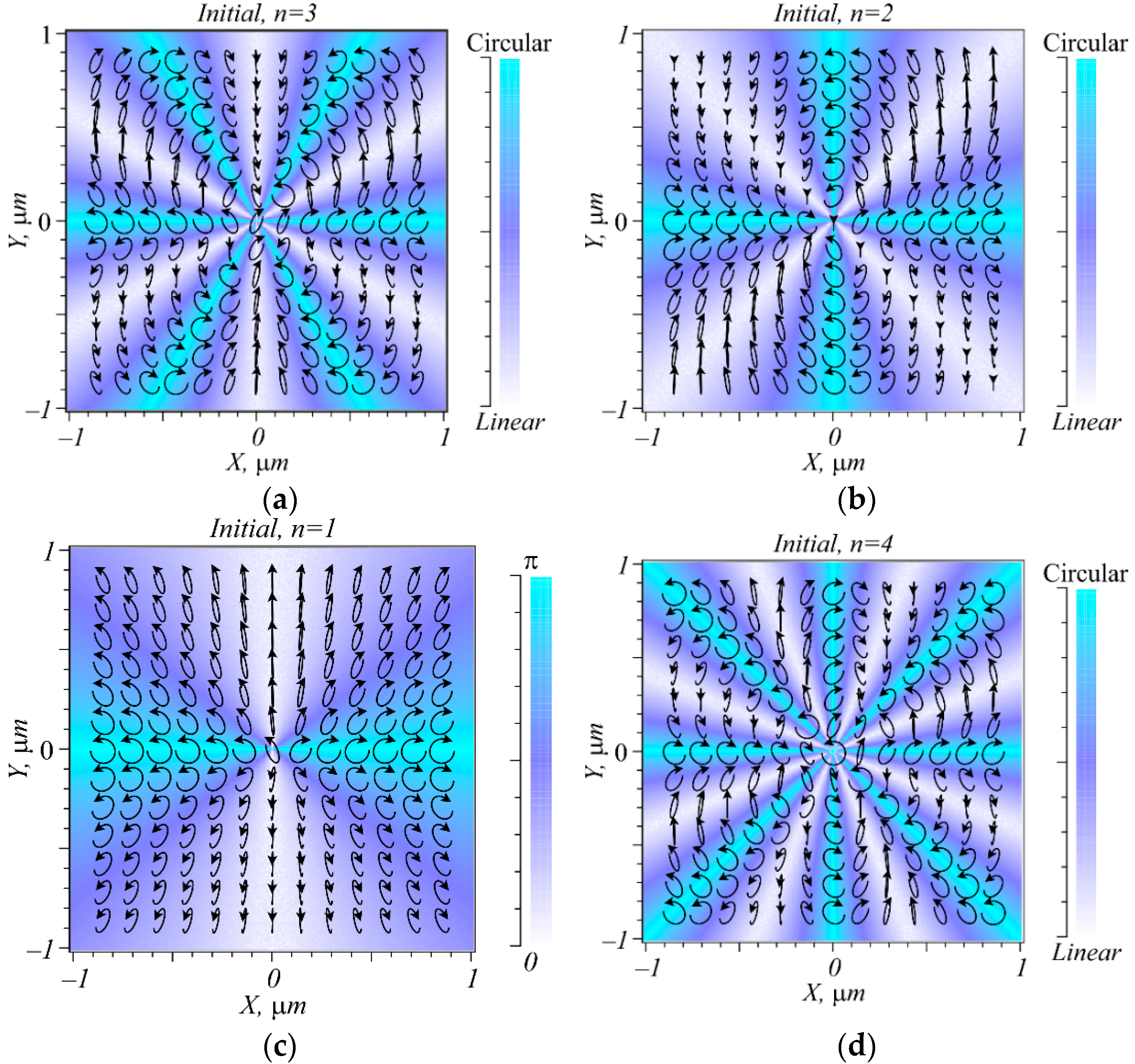
Figure 1 depicts a distribution of polarization ellipses in the source field (1) at different
n: 3(a), 2(b), 1(c), and 4(d). Indices for C-lines of the fields in
Figure 1, derived from Equation (7) using a complex Stokes field, equal
Ic =
σ/2 =
n/2: 3/2(a), 1(b), 1/2(c), and 2(d). From
Figure 1a, field (1) with
n = 3 is seen to have three C-lines located at angles
φ =
πm/3,
m = 0, 1, 2. The tilt of the major axis of the polarization ellipses changes by
π/2 at each of six sectors between the adjacent C-lines. Thus, after a full circle, the tilt of the major axis changes by 6
π/2 = 3
π, meaning that the index of the field in
Figure 1a is
Ic = 3
π/(2
π) = 3/2. In a similar way, in
Figure 1b, field (1) with
n = 2 has two C-lines located on the Cartesian axes. With the angle
φ in a sector between C-lines changing from 0 to
π/2, the tilt of the major axis of the polarization ellipse is rotated by an angle of
π/2; hence after a full circle around the center, the tilt of the major axis changed by 4
π/2. Hence, the index of the field in
Figure 1b equals
Ic = 2
π/(2
π) = 1. In
Figure 1c
, the C-line is found on the horizontal Cartesian axis. With the angle
φ in one of the sectors between C-lines changing from 0 to
π (in the upper semi-plane), the tilt of the polarization ellipse major axis is rotated by
π/2, and in the bottom semi-plane, the tilt of the major axis is also rotated by
π/2. Hence, after a full circle, the polarization ellipse makes a turn by
π, and the singularity index equals
Ic =
π/(2
π) = 1/2. Finally, in
Figure 1d, a change in the tilt of the major axis of polarization ellipses can be analyzed in a similar way.
Shown in
Figure 2a is a total intensity at the focus of field (1) at
α = 1 and
n = 2. The numerical modeling was conducted using a Richards–Wolf formalism [
16] for a wavelength of λ = 532 nm and numerical aperture NA = 0.95. Shown in
Figure 2b,c are an amplitude and phase of the complex Stokes field
, which was calculated with the aid of the Stokes vector components in Equation (19). From
Figure 2a, it is seen that according to theoretical predictions in Equations (16) and (17), the intensity pattern at the focus remains unchanged after replacing
φ by
φ +
π, with an intensity peak located at the center. From
Figure 2c, it is seen that there is no singular point at the center of the phase pattern for the Stokes field (20), because there is no isolated intensity null. Two isolated intensity nulls (singularity points) in
Figure 2c, each having the topological charge 1, are seen on the vertical axis (1 and 2 points in
Figure 2c). In
Figure 2d, the arrows specify a pattern of the polarization ellipses at the focus.
Figure 2e depicts C-points at the focus, which are all located on the Cartesian axes; it is where the C-lines are located in the source plane (
Figure 1b). Thus, the numerical modeling has shown that as a result of tightly focusing, C-lines ‘disintegrate’ into a number of C-points arranged on the same lines. This effect is analogous to an effect of astigmatic edge-to-screw dislocation conversion of a wavefront in scalar paraxial optics [
20]. Indices of two symmetrical and closest to the center C-points on the horizontal Cartesian axis are
Ic = +1/2 (1 and 2 points in
Figure 2e), with the indices of the next two neighboring C-points located farther from the center on the horizontal axis being
Ic = –1/2 (3 and 4 points in
Figure 2e).
In a similar way,
Figure 3 depicts the numerical simulation results at the focus for
n = 3 (the rest of the parameters being the same as in
Figure 2).
Figure 3a suggests that in agreement with the theoretical prediction in (16), the intensity pattern at the focus at odd
n = 3 is asymmetric. As can be inferred from (19), there is a vector field with purely inhomogeneous linear polarization at the focus (
Figure 3d), as putting
n = 2
p + 1, we obtain
. In a phase pattern of the complex Stokes field in
Figure 3c, there occurs three phase singularity points with the topological charge +2 (1, 2, and 3 points in
Figure 3c). In total, the Stokes index is
σ = 6, and the V-points singularity index is
η =
σ/2 = 3. The pattern in
Figure 3d is seen to contain three V-points (two points of the ‘center’ type and one point of the ‘knot’ type). Thus, when field (1) has an odd order
n, the C-lines (
Figure 1a) of the original plane are transformed into a number of V-points (
Figure 3d), and the whole field becomes vectorial (with no points of elliptical polarization).
Shown in
Figure 4a is an intensity pattern at the focus, which has a fourth-order symmetry relative to the Cartesian coordinates. The amplitude and phase of the complex Stokes field are depicted in
Figure 4b,c. Phase singularities points linked with the C-points are observed in the phase pattern of the Stokes field (
Figure 4e). Finally,
Figure 4f depicts a plot for the Stokes index σ against the radius
R of an origin-centered circle along which the phase delay of the Stokes field (20) of
Figure 4c is calculated. From the plot, it is seen that at different radii
R, the Stokes index takes values of 8, 6, 2, 0, which is in good agreement with the theory in Equation (20).
From
Figure 4e,d, the C-points are seen to lie on the Cartesian axes and two diagonal lines, where C-lines were located in the original plane (
Figure 1d). Two center-symmetrical C-points located on the horizontal axis (
Figure 4e,f) have a singularity index of +1/2, producing a ‘lemon’-shaped topology. Remarkably, when making a circle around such a C-point, the surface of the polarization ellipses produces a Mobius strip in the 3-D space [
21,
22,
23].
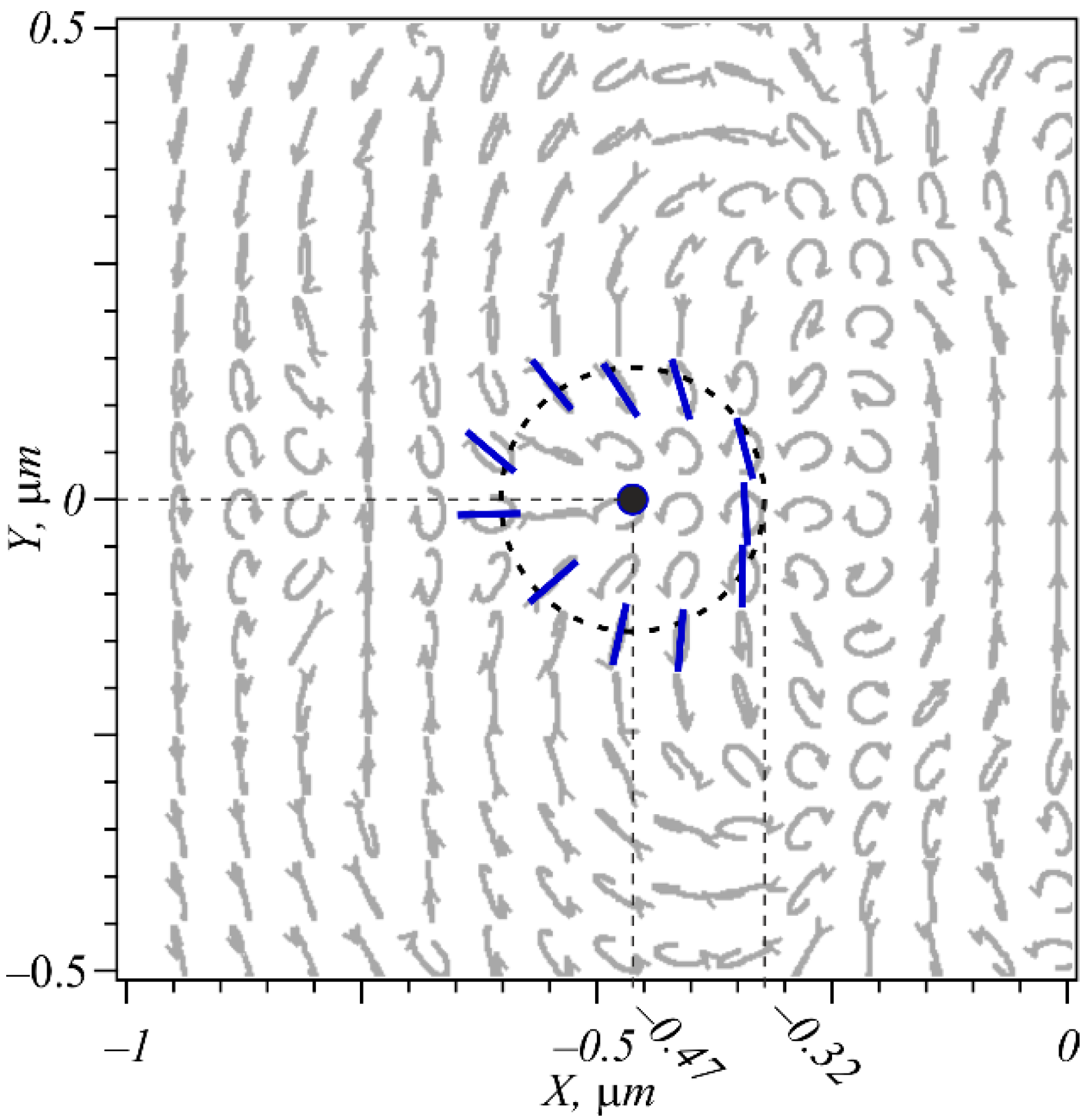
Figure 5 depicts the neighborhood of a C-point (marked with bold black) in more detail, showing a characteristic tilt of the major axis of polarization ellipses (‘lemon’-type topology) lying on a circle centered on the C-point. The axes of the polarization ellipses are seen to turn by an angle of
π when making a full circle, i.e., the index of the C-point equals 1/2.
5. Discussion
The key result of this work is the use of the global characteristics of the polarization singularities of the entire beam as a whole, rather than the analysis of local polarization, Stokes and Poincare–Hopf indices [
3]. For this, we extended Berry’s concept [
12] of the topological charge of scalar beams to structured vector beams. We have shown in our work that
n C-lines in the initial hybrid field (1), in a sharp focus, decay into
n separate C-points with an index of 1/2. The instability of V-points and C-lines was shown earlier for paraxial laser beams [
24] and in uniaxial crystals [
25]. It was shown in [
24] that in the superposition of two Laguerre-Gauss vector beams with azimuthal numbers
m and
n,
V-points are formed in the initial plane, which, when this superposition propagates, decay into 2
C-points. That is, the initial vector beam with linear polarization at each point turns out to be unstable, and, during propagation, points with both elliptical and circular polarizations are formed. It is shown in another work [
25] that, depending on the magnitude of the delay between the ordinary and extraordinary rays in a uniaxial crystal, the axis of which is rotated by 45 degrees, C-line decays into two C-points.
We named the light field (1) a hybrid vector beam to differ it from vector cylindrical beams [
4], which have only linear polarization in their cross section. In the light beam (1), depending on the azimuthal angle, the polarization changes from linear to elliptical and circular several times. Light fields with hybrid polarization of other types other than (1) are investigated in [
26,
27,
28,
29,
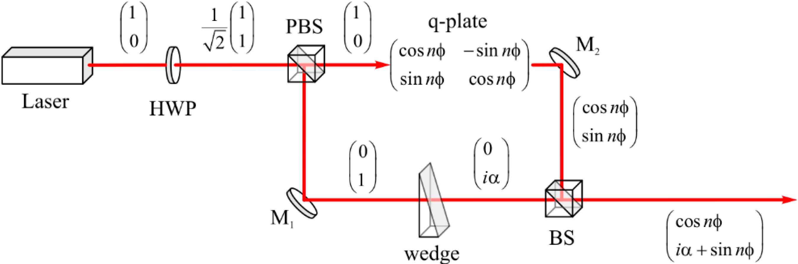
30]. A hybrid vector beam (1) could be generated using the optical setup shown in
Figure 6.
Linearly polarized light from the laser is shown in
Figure 6 to propagate through a half-wave plate, which rotates polarization onto 45 degrees. After a polarizing beam splitter, there are two propagating beams with orthogonal linear polarization. The first beam propagates through a liquid crystal q-plate and acquires a cylindrical vector polarization of the
nth order. In addition, the second beam propagates through a wedge and acquires a phase delay, which can be adjusted by shifting the wedge. After a beam splitter, both beams became hybrid and satisfies (1).
Concluding this section, let us explain the application of Berry’s formula (6) to determine the singularity index of the hybrid field (1). Berry’s formula is usually used to determine the topological charge of scalar optical vortices. Scalar optical vortices also have an orbital angular momentum, which is calculated by another formula, different from (6). In this paper, we have extended the application of Berry’s formula (6). We applied it to calculate the polarization singularity index of any vector field for the first time. If the vector field has one V-point, then the Stokes index (6)
σ will be two times greater than the Poincare–Hopf index [
3] (
η =
σ/2), which is equal to the singularity index of the V-point. If the field has one C-point, then the Stokes index (6) will also be two times greater than the singularity index of the C-point (
Ic =
σ/2). However, if we apply formula (6) to the entire vector field, which can contain several V-points and several C-points, then the Stokes index (6)
σ will be equal to the doubled sum of the indices of all singularity points.


