1. Introduction
Recently, interest in optical vortex signals (or OAM—orbital angular momentum [
1,
2,
3] signals) has already shifted from research to a purely practical plane. In this regard, the issues of generating, converting, processing, and receiving signals of this kind based on relatively inexpensive and accessible components are gaining importance, because they can, firstly, be implemented on commercially available devices, that can be used for this purpose directly or by slight modernization, and, secondly, it will allow developing OAM systems without free-space optics (FSO) segments, i.e., by fiber optics only. The second circumstance determines the “entrance ticket” of optical vortex technology to the practical implementation and operation of such systems within the telecommunication industry and the industry of control (sending) systems. Therefore, taking into account the breadth of possible applications of optical vortex signals—from multiplexing systems [
1,
3] (etc.) to highly specialized applications, for example, the creation of fiber-optic physical level secured communication systems [
4], the development of a method for generating OAM utilizing fiber-optic that are standardly interfaced with a fiber-optic transmission line (FOL) seems to be an urgent technical problem.
It should be additionally noted that the use of optical vortex signals is relevant for non-extended fiber-optic lines due to both the significant mutual transfer of energy between the fiber-optic modes at distances of the order of the standard regeneration section (about 100 km) and more, and the OAM instability (in terms of wavefront purity) when passing such distances. Nevertheless, for short fiber-optic lines serving urban-scale networks (xPON networks and the like), as mentioned above, many urgent problems can be solved using vortex signals. However, nowadays within this type of networks, as a rule, there radio-photonic (fiber-optic-radio-air) segments or RoF (Radio-over-Fiber [
5]) links are also deployed, which ensure the invention of 5G technologies [
6,
7,
8,
9], the implementation of Smart City programs, “Smart road (highway)”, “Smart manufacturing”, “Smart home” and the like, one of the basic properties of which are two-frequency (in the general case, multi-frequency) optical signals. In addition, a two-frequency, or rather, a polyharmonic signal, is interesting in distributed sensor networks, for which, as it will be shown below, OAM is also an interesting and promising phenomenon. Moreover, it was shown in [
10] that vortex modes can be used in RoF technology for capacity increase. Therefore, the generation of OAM signals on such systems should be performed not under the conditions of a single radiation wavelength
λ0, but in the presence of several (albeit close, but still noticeably different) wavelengths, for example,
λ1 and
λ2. There are many publications describing generation of OAM signals by means of fiber optic: using helical fiber grating [
11,
12], microstructure and photonic optical fibers [
13,
14]
In this regard, the purpose of this article is to study the possibility of using a vortex fiber-optic Bragg grating (V-FBG) to form an optical vortex signal in the presence of two optical carriers, which are subsequently used (at the remote end of the line) to form a difference radio frequency signal in radio optic systems. The task is also to establish the optimal parameters of such a grating.
2. Usage of OAM in Sensor Application and the Problem of the OAM-Based Address Formation for a Polyharmonic Signal in Sensor Networks
When constructing fiber-optic and radio-photonic sensor networks (RPSNs) based on a plurality of fiber Bragg structures (FBS), there is a task of getting a unique address for every sensor element (grating). The complexity of this task is due to the high cost of interrogation devices, associated with the applied sensor multiplexing technologies, such as wavelength, time, frequency, polarization and spatial division multiplexing [
15,
16,
17,
18]. The complexity of the multiplexing technology applied and polling technologies is also explained by another important factor—the polled sensors, as a rule, are not adapted for address polling, therefore any overlap of the FBS spectra leads to significant measurement errors. For this, it is necessary to ensure the complete separation of responses from sensors operating in the same frequency range. In turn, this requires the use of optical effective orthogonal codes.
As a rule, in modern RPSNs, interrogation of spectrally-encoded FBS is performed in real-time by determining the autocorrelation function between the spectrum reflected from the sensor and its code signature [
15,
16]. Several works have demonstrated the detection and tracking of sensors for efficient measurement of temperature and deformation even in the case of overlapping spectra using Slepyan codes based on orthogonal discrete extended spheroidal sequences [
15,
16]. However, for their interrogation, a source of two-frequency scanning radiation and an electronic vector analyzer are required to carry out additional calculations and processing. In this case, addressing can be provided by normalizing the power of the luminous flux by creating two channels—a reference one without an inclined filter and a measuring one with an inclined filter. However, the described system has such a disadvantage as the need to use additional equipment, e.g., specialized filters, as well as additional channels that should be used as reference. At the same time, these measurements do not provide an unambiguous reading of the address. Thus, additional difficulties arise in determining the central (Bragg) frequencies of the addressable fiber Bragg structures (AFBS) in the array of sensors, as multiple cross beats of all frequency components that form the address frequencies of the AFBS can arise in the system.
The indicated drawback was partially eliminated due to the application of the method of processing the complex signal received from the AFBS array with the same central frequency and various difference frequencies. This method made it possible to solve the problem of unambiguous determination of the positions of the central frequencies of all AFBSs in the array of sensors [
15,
16]. But if the RPSN size increases, the listed problems will arise again. Therefore, it seems relevant to find an additional, physically independent from the above parameter, which can be used to transmit information, as well as for the formation of the FBG sensor address as part of a complex sensor network.
Therefore, according to the facts mentioned above, it is proposed to use the vortex phase state of the wave front, or the same, orbital angular momentum, as a frequency (wavelength) independent parameter of the optical signal. The use of such an additional parameter will significantly expand the orthogonal signal basis and the structure and capabilities of RPSN, as well as provide the possibility of fully optical signal processing. Thus, the analysis of a signal in the optical domain is possible using a tunable phase filter (or diffractive optical element, DOE), which in a very wide frequency range practically does not correlate with a measured parameter based on a change in the frequency (wavelength) or the frequency difference of optical radiation. This eliminates the need for additional reference channels, which again leads to the expansion of the RPSN capabilities.
In general, the use of OAM in sensor technologies has already demonstrated the significant potential of this approach. For instance, the authors of [
19] proposed an optical sensing method and signal demodulation technique based on a Mach–Zehnder interferometer (MZI) and a beam carrying orbital angular momentum. The MZI consists of two different branches: one with a single-mode fiber (SMF)—this path emits a Gaussian beam; the second branch is a segment of two-mode fiber (TMF), that carries an OAM beam. The OAM beam in this setup was formed by offset splicing the TMF segment to the SMF. The TMF has been rotated using a tunable fiber rotator. The interference between the Gaussian beam and the OAM beam creates a has a spiral pattern that is sensitive to the change in the phase difference between the two beams, which causes rotation of the interference pattern. In [
19], a single-mode fiber branch carrying a Gaussian beam was used as a sensitive fiber, which was placed on a thermostat. The temperature change led to the corresponding increment in the phase difference between the OAM beam and the Gaussian beam due to the thermo-optic effect and the thermal expansion effect of the sensing fiber, and the phase difference caused proportional interference pattern rotation. The authors proposed a method of extracting the characteristics of a spiral interference pattern to demodulate the optical phase difference between the two beams considered. According to the experimental results obtained the sensor system proposed in [
19] has a linear temperature measurement sensitivity of 12.67 rad/°C. The theoretical resolution of the temperature measurement is 0.0000122 °C and in the experiment, it is approximately 0.005 °C.
In papers [
20,
21], a design of a fiber-optic sensor based on OAM was proposed and an analysis of its performance when measuring deformation and temperature was carried out. The main idea of this work is also based on the fact that the beam propagating along the fiber can be expressed as the sum of the fiber modes. The relative phase of these modes fluctuates due to different mode propagation constants. For example, the TE01 mode propagates slightly slower than the TM01 mode. The relative phase between any two modes is
φ = 2π⋅(
neff, 1 −
neff, 2)⋅
L/
λ, where
L is the fiber length,
λ is the wavelength in free space, and
neff, 1,
neff, 2—effective refractive indices of the two indicated modes. As the relative phase between TM01 and TE01 modes changes, the average OAM per photon tracks a sinusoidal function: OAM = sin(
φ)⋅ħ/photon, where
φ is the relative phase between TM01 and TE01 modes.
As an example, a deformation and temperature sensor of an optical fiber was numerically simulated. To obtain an estimation, a TMF with a stepped refractive index profile was chosen (V = 3.695, core radius = 2.6 μm,
ncore −
nclad = 7 × 10
−3). It was assumed that the ratio is equal for the TE01 and TM01 modes, namely, in the strain gauge, the modes propagate based on the effective refractive indices of 1.4640 and 1.4641, and the fiber length is increased by a small amount (0.1% relative change). In the temperature sensor considered in [
20], temperature fluctuations lead to a proportional change in the refractive index and an increase in the fiber length; in addition, the mode composition of the optical fiber is recalculated for each new refractive index profile. Small deviations of the OAM from the ideal shape are due to the discreteness of the computational model used to calculate the fiber-optic modes, which leads to numerical errors. In the works under consideration, the initial length of the optical fiber is 10 m, while the authors neglected the coupling between modes, as the difference between the effective refractive indices was approximately 10
−4. As a result of the simulation, the authors obtained the average value of the OAM per photon, which can be measured using the twisting method presented in this work.
As a result of numerical simulations, the authors of [
20] found that the smallest measurable change in the average OAM using a cylindrical lens and a camera system is about 0.01 per photon. As mentioned above, the fiber sensor simulated in [
20] has a length of 10 m, the difference between the effective refractive indices is 10
−4 and the OAM measurement sensitivity is 0.01⋅ħ/photon, which provides the smallest measurable change in length of 15 μm or 1.5 microstrains (1 microstrain ≅ 10
−6 Δ
L/
λ), while the smallest measurable temperature fluctuation is about 0.14 °C. It should be noted that the accuracy of this fiber-optic sensor is very high compared to alternative solutions: for example, multimode fiber-optical interference sensors can measure the length increment corresponding to 0.56 microstrain, while having a temperature sensitivity of about 0.17 °C. Thus, as shown in [
20], sensors based on the orbital angular momentum have a very high sensitivity, which in the future can be improved by increasing the difference of effective refractive indices, increasing of fiber length, and potential reduction of the smallest measurable change in topological charge, i.e., in OAM order.
However, in the works presented [
19,
20,
21], the OAM was used not concerning the polyharmonic signal, which allowed the authors of the listed works to quite unambiguously form the response of the sensors. In the considered case, i.e., forming an address based on OAM for a polyharmonic signal in sensor networks, the question arises about the structure that forms the OAM: how will OAM be formed with two-frequency radiation (at two close wavelengths
λ1 and
λ2), coming, for example, from two interacting lasers? The specified method of signal forming is very common in the context of RPSN development. The question is, if the forming OAM structure is matched with
λ1, then what can we say about the signal on
λ2? Will OAM be formed at
λ2 and how significant the phase mismatch Δ
ϕ will be?
Finally, the authors of this article have also shown the application of chiral fiber Bragg grating (ChFBG) as an addressed sensor [
22]. ChFBG, proposed in [
22], can be used as an alternative solution to a two-frequency sensor addressable system in which the difference between these frequencies is used as the grating address. Two ChFBGs having opposite chirality can form OAM signals of opposite orders: −1 and +1; in addition, the classical fiber Bragg sensor “generates” (reflects) a Gaussian mode, i.e., zero order OAM. Thus, it is possible to use three spatial modes (OAM −1, 0, +1) at the same wavelength, while the OAM order will be a unique address of each grating due to the spatial orthogonality of the OAM modes; one can separate these so-called vortex modes using fiber mode splitters and other similar mode-division multiplexing devices. The use of two ChFBGs can potentially triple the capacity of addressable sensor systems; moreover, chirping and apodization of ChFBG will make it possible to achieve the required spectral characteristics. The manufacture of such arrays is a non-trivial technical problem; however, the promising potential allows us to consider ChFBG as a worthy alternative to polyharmonic addressable sensor systems. Moreover, the possibility of using chiral fibers as sensors has been shown in many works such as [
23,
24,
25].
Consequently, the use of OAM in sensor technologies seems to be quite interesting and can provide a significant development of RPSNs with AFBS, which is confirmed by many papers published in this field. But at the moment, the problem of the possibility of using OAM in polyharmonic systems remains unexplored, which is the object of this article.
3. Scheme of OAM Formation for Two-Frequency RPSN and Temporal Evolution of the Two-Frequency Signal
Consider one of the simplest and most common cases: RPSN based on the use of a two-frequency optical signal which is the result of combining radiation at two close wavelengths
λ1 and
λ2 from two lasers,
Figure 1. This scheme has drawbacks but is nevertheless convenient for obtaining a radio frequency (difference frequency, Δ
λ = |
λ1 −
λ2|, corresponding to a radio frequency) signal in a wide range—from several tens to several hundred GHz [
26], that is relevant for a wide class of RPSN. To generate OAM signal in the scheme shown in
Figure 1, it is proposed to use a directional splitter (circulator) at the output of the lasers and the V-FBG element, which can be obtained, for example, based on the existing method of separate (individual) burning of fingers of long-period FBGs, but with a continuously switched on UV laser and with simultaneous rotation and longitudinal drawing of the optical fiber preform. This technology is now developing [
27] and the details of the implementation of a specific production process will subsequently be worked out and refined.
For definiteness, let the V-FBG element work to reflect the incoming optical signals (the reflecting FBG). In principle, this does not violate the generality, as it only defines the V-FBG switching circuit. Consequently, in this case, the main light-guiding mode
LP01 enters the grating (for each of the two radiations, i.e., both at
λ1 and
λ2), and the reflected waveguide mode, which is carrying OAM (at both wavelengths), can no longer be
LP01, but must be at least
LP11, or a higher order mode (s). This is because
LP01 has symmetric field distribution in the plane orthogonal to the fiber axis [
28]; therefore, “twisting” it (to obtain OAM) will allow obtaining only a degenerate case, which is not of particular interest. Therefore, let us assume for definiteness that the reflected mode is
LP11. In order for these two modes to propagate along the optical fibers of the circuit in
Figure 1, we additionally define that at the selected wavelengths (for telecommunications, the most interesting is the C-band for DWDM, i.e., in the vicinity of 1550 nm), the fibers are not strictly single-mode, and thus allow a few-mode propagation mode (by analogy with the scheme in [
4]).
The two lasers used in the scheme are assumed to be interacting, as a fraction of the reflected radiation falls back into the resonators (this effect was observed in an experimental study of the considered scheme with two radiation sources [
26], although the components used were characterized by high stability of parameters). Therefore, we reckon there is a temporal character of the change in the functions of the radiation intensities of lasers
I1(
T) and
I2(
T). The latter will inevitably affect the formation of OAM, in addition to the fact that the radiation is two-frequency; this fact must be quantitatively estimated and taken into account when carrying out these studies.
For engineering modeling of the total signal, we will use a modified description of the intensities
I1(
T) and
I2(
T) of two lasers with resonator coupling, by analogy with [
29], obtained from the general model [
30]:
where
N1 and
N2 are the normalized (by the value of
N0 in an unexcited state) concentration of nonequilibrium carriers for the considered semiconductor lasers L-1 and L-2;
kf1 and
kf2 are the intensity-dependent feedback coefficients that determine the effect of the back reflected radiation into the laser on the recombination of charge carriers in the cavities;
k12,
k21—coefficients of the injection relationship of laser resonators;
P1 and
P2 are the pump parameters:
P1,2 (
T) =
J1,2/
Jth, where
J1 and
J2 are the pump currents of the lasers, respectively, and
Jth is the threshold pump current for a laser without feedback (we consider these values to be approximately the same in the case under consideration);
Gn is a parameter characterizing the dynamic mode gain of the laser cavity associated with the radiation intensity (we assume that both lasers are structurally similar):
. Here,
δω is the difference between the frequencies of the incoming optical radiation and the working quantum transition of the electron;
τs is the lifetime of nonequilibrium carriers;
I0, n—saturation intensity,
γ is aspect ratio.
The time T included in the system (1) represents the normalized value of the current time t by the lifetime of photons in the cavity τth, T = t/τth (we also reckon that both lasers have approximately the same dynamic properties), the coefficient Ts = τs/τth characterizes the performance of the laser medium; τ1 and τ2 are the propagation times of radiation from the L-1 (L-2) laser to an arbitrary (under consideration) point of the fiber-optic path of the RoF line (possibly to a point or region of effective reflection). The coefficients kf1, kf2, k12 and k21 are not strictly constant over time; moreover, they should represent the random nature of fluctuations (superimposed on a deterministic constant weighted average) inherent in the physical process of recombination. In system (1) it was also taken into account that the change in the radiation efficiency is directly proportional (γ) to the pump parameters and the amplification parameters of the laser medium and is determined by the concentration of nonequilibrium carriers and the intensity of this radiation. The “minus” sign in front of the first term on the right-hand side in the first two Equation (1) indicates that after switching on the lasers, the changes in their intensities are the more significant the further the current intensity is from the steady-state normalized value.
In the problem under consideration, the RoF link is not assumed to be long, for instance, it should be about 10 m as in [
20]. As was mentioned, we consider the propagation of
LP01 and
LP11 in few-mode fiber over this length which can lead to significant depolarization. To avoid this one can use a fiber polarization controller (
Figure 1) which makes the setup more complex but still usage of different modes can improve the capacity of RPSN. The characteristic distortion factors in such a short line are radiation reflected back into the laser and a decrease in the dynamic range of optical signals. Therefore, arguing by analogy with [
30], we define the functional coefficients
kf1 and
kf2 as directly proportional to the corresponding intensities through the introduced coefficients
k11 and
k22. We also take the average intensities
assuming that the delays
τ1 and
τ2 are approximately the same. Given the above, system (1) takes the form:
As above, we assume that all the coefficients k11, k22, k12, k21 should characterize the random nature of the recombination process.
It should be noted that as the duration of the delay for the reflected signal in the line is no less than an order of magnitude longer than the duration of the signal delay in the laser cavity, we assume that the derivatives
∂N1,2/
∂T ≅ 0. Then, from expression (2) it follows:
Figure 2 shows the results of the numerical solution of Equation (3) performed for two typical cases of reflection on the fiber-optic communication line of RPSN:
k11 =
k22 =
k12 =
k21 = 0.005 (1 +
θ) and
k11 =
k22 =
k12 =
k21 = 0.025 (1 +
θ), where
θ is a random variable in the range [−1, 1] with a uniformly shifted distribution in the positive area. Based on the diagram depicted in
Figure 1 it was assumed that the delay parameter should obey the condition
τ ≤ 1000·
τth. The coefficients characterizing the properties of lasers were set as follows:
γ = 1,
J1,2 = 2,2
Jth,
= 0.5, i.e., the process was studied at constant pump currents,
= 1,
τS = 1
ns, and
τth = 1 ps. The frequency difference
δω of the incoming optical radiation (into the laser, which is associated with reflection) and the working quantum transition of an electron was taken as equal to
δω = 6.28 × 10
11 rad/s, which corresponded to a radio frequency of 100 GHz, and the value of the wavelengths difference was about Δ
λ = 0.8 nm, which was calculated relative to the wavelength
λ0 = 1550 nm. For both lasers, the value
δω was the same, since they were under the same conditions: the reflected radiation from the neighboring laser is separated by Δ
λ.
It can be seen from the graphs that after switching on the lasers, their intensities for a time of the order of τS, on average, slightly decrease relative to the initially set value (corresponding to the typical value of the intensity on the fiber optic link I0 ≅ 0.4 mW/μm2) with small fluctuations in the transient mode, and then steady average values are observed with somewhat more noticeable fluctuations. The average spread of values can be of the order of 20 μW/μm2 for a time of the order of 100 ÷ 200 ps (with the chosen parameters of the circuit), which leads to the additional fluctuation frequency ≈ 5 ÷ 10 GHz. In this case, the fluctuation amplitudes are characterized by a quasiperiodic change—with their increase for I1(T), a decrease is observed for I2(T), then the opposite occurs. The average period of such a temporary change is of the order of ~ 2000 ÷ 2200 ps, which means that the additional frequency ≈ 0.45 ÷ 0.5 GHz appears. The frequencies and are determined by both the dynamic properties of the lasers and the value of the detuning δω (more precisely, the ratio of the detuning to the spectral properties of lasers).
Based on the performed quantitative estimation for
and
, as well as analyzing the system of Equation (3), it can be seen that the radio frequency δω, which is one of the defining parameters of RPSN, indirectly determines the values
and
. The parameter
δω is inversely proportional to
Gn, which determines the term characterizing the effect of the intrinsic laser (on the character of the intensity change) in Equation (3). Consequently, with an increase in
δω one should expect a decrease in
Gn and, hence, an increase in the influence of the reflected signal. Hence, one can conclude there is a possible upper limit
δωmax for the selected parameters of the circuit, at which the considered fluctuations, even without the formation of OAM, can negate the technical advantages of using a polyharmonic signal. Note, that the small value
δω may be close to the
and
, the influence of which can noticeably affect the RPSN measurements performed (or it will lead to a wise choice of the lasers’ parameters). The analysis of the influence of the two-frequency signal generation circuit properties on the parameters of polyharmonic RPSN seems to be very interesting but is not the subject of this article. Within the framework of this article, we only take into account these fluctuations in the OAM generation using the scheme depicted in
Figure 1.
4. Model of the Vortex Fiber Bragg Grating (V-FBG) Output Signal
As mentioned above, the
LP01 mode arrives at the input of the V-FBG, and
LP11 is formed at the output (in reflected light), which is shown in [
31] using the coupled modes theory [
32]. Assuming that the optical fibers used in the circuit according to
Figure 1 can be considered as weakly guiding [
27], for the electric field strength of light waves, we write:
where
rco is the radius of the fiber core (we assume that the V-FBG is obtained on the basis of an optical fiber preform, the same as used in the circuit for connecting components);
β01 and
β11 are the phase coefficients of the incident (OAM = 0, plane wave) and reflected modes (OAM = 1, in this paper we will consider first-order vortex signal only), respectively;
J0 is the Bessel function,
unm are the values of the first maxima of the Bessel function and its derivative
J1,
and
are the amplitudes of the corresponding modes. Note that
, where
I(
T) is the intensity of radiation at the first
λ1 wavelength (or the second wavelength
λ2, emitted by laser,
Figure 1), arriving at the input of the fiber-optic grating;
- wave impedance of the guiding structure (optical fiber) for the considered mode. To set OAM = 1 for
LP11, we write:
(hereinafter, to shorten the notation, we assume the generalized wavelength −
λ0; in addition, we note that, if necessary to obtain OAM with a higher topological charge, i.e., above 1, this can be given through
φ = 4π…, 6π… etc.). Note that, in Equation (5) it is assumed that, for instance,
ELP11 =
LP11even +
iLP11odd, i.e., we consider superpositions of phase shifted
LP modes with the same order and orthogonal polarizations—these superpositions form OAM-carrying waves.
In order to determine the phase coefficients and the characteristic impedance in Equation (4), we assign the modes (more precisely, the considered linearly polarized modes) to the type of waves or the hybrid modes of the guiding structure. For optical fibers with a step-index profile of the refractive index in [
33], the following correspondence table is presented, see
Table 1.
We assume that in our case the linearly polarized
LP01 mode corresponds to the wave type
HE11, and the
LP11 mode corresponds to the wave type
TE01 (magnetic
H01-wave, for which
Ez = 0,
Hz ≠ 0), see
Figure 3.
Let us determine the coefficients β01 and β11 for the wave types considered in this paper. For the first of the considered modes, the relationship between the effective refractive index of the guiding structure (fiber core) and the phase coefficient for the fundamental mode can be represented as: . Since the Bragg grating is a structure of “light” and “dark” regions (stripes) along the fiber with a modulation amplitude of the refractive index , we assume: , where n0 corresponds to the refractive index of the core of the optical fiber preform.
To determine the phase coefficient of another mode considered in this problem, we write [
19]:
, hence:
for a medium with
n = 1, where the critical wavelength for oscillations of the selected H-type in a circular waveguide is determined by:
From here it follows
Accordingly, the wave impedances for the modes are defined as:
, where
λcr, HE11 = 3.41·
rco and
λcr, HE01 = 1.64·
rco [
34].
Let the V-FBG, as in [
22], be characterized by the refractive index in accordance with the relation:
where
g(
z) is the apodization function characterizing the longitudinal shape of the grating finger (for example, if
, then the optical intensity oscillates harmonically), parameter
B0 is determined by the properties of the grating:
, where
ΛBr is the Bragg reflection wavelength;
ΛCh—chirp multiplier. The degree of the V-FBG twist (i.e., how many turns does a grating make over the length
ΛBr) depends on the angle
φ. So, to obtain OAM of the first order, the following condition must be met:
. The radial function
f(
r) characterizes the degree of mode coupling [
31]. It is also shown there that in order to provide a unit modulus of the overlap integral of the modes under consideration (which means almost complete transfer of energy from the input mode to the output mode), the specified function should have the form
where
σ is the normalizing coefficient:
. The exact values of the effective refractive indices, as well as the phase coefficients
β, can be found by numerically solving the characteristic equation of the step-index optical fiber [
8] and, for instance, we can write
β01= 5946 × 10
6 and
β11= 59,383 × 10
6 for OFS FMF. According to the methodology outlined in [
31], the period
L of the Bragg grating forming the
LP11 mode must be
L =
ΛBr/(
n01 +
n11) to ensure the phase matching condition (in the case of the classical FBG, which, as is known, does not change the mode composition of the reflected radiation, we obtain
L =
ΛBr/2
n).
Further, in order to determine the modulus of the electric intensity vector of the reflected lightwave from Equations (4) and (5), we should write down the relation for electric induction [
34], which is true in the case of non-magnetic media:
which follows to
Setting
n in the form (5), we get:
To obtain the final form of (7), transformations similar to ones given in [
31] are performed. Relation (7) shows that at the output of the B-FBG, radiation characterized by a factor
is actually generated. The parameter Δ
β, written by analogy with [
32], turned out to be:
Now it seems interesting to carry out a simulation of expression (7) taking into account the following properties of the signal:
- (1)
A destabilizing factor—the intensity fluctuation of the input mode, and
- (2)
The two-frequency radiation character.
The second property means the presence of an optical radiation wavelength that is mismatched with the design parameters of the V-FBG, in particular, under the condition λ0 ≠ in the notation (7).
5. Simulation of the V-FBG Output Signal with the Influence of the Input Mode Intensity Fluctuation and the Two-Frequency Property of the Radiation
Figure 4 shows the results of calculating the growth parameter of twisted radiation
along
z, written in terms of the Bragg wavelength:
. It was assumed:
g(
z) = 1,
n0 = 1.48,
λ0 = 0.9
λcr,
= 0, Δ
n was taken equal to 0.01
n0 (curves 1) and 0.001
n0 (curves 2). The graphs are obtained for the area
. It can be seen that in the typical case of FBG manufacture (i.e., in the layered UV-burning technique, when Δ
n is determined mainly by the third decimal place [
27,
31]) should be long enough (case 2)—for effective light twisting, it is necessary to ensure the length of
LV-FBG ≥ 400
∧Br. To reduce
LV-FBG by at least 2–3 times, it is necessary to increase Δ
n by an order of magnitude, which, in turn, will most likely require technological changes in the manufacturing process of such a grating.
We will reckon now that the V-FBG length is chosen sufficiently long (
LV-FBG = 400∧
Br), which will allow us to neglect the term
in (7). In order to take into account the influence of the temporal nature of the input mode intensity, here one should change the
z coordinate to the current time
t, and for the correctness of the comparison—to the normalized time
T. According to [
34] the phase velocity is
, then for
LP01 it will turn out to be:
which provides the following substitution in (12):
. Taking into account the above relationship
and
, see the explanation to (4), relation (7) for the radiation at the V-FBG output can be rewritten as:
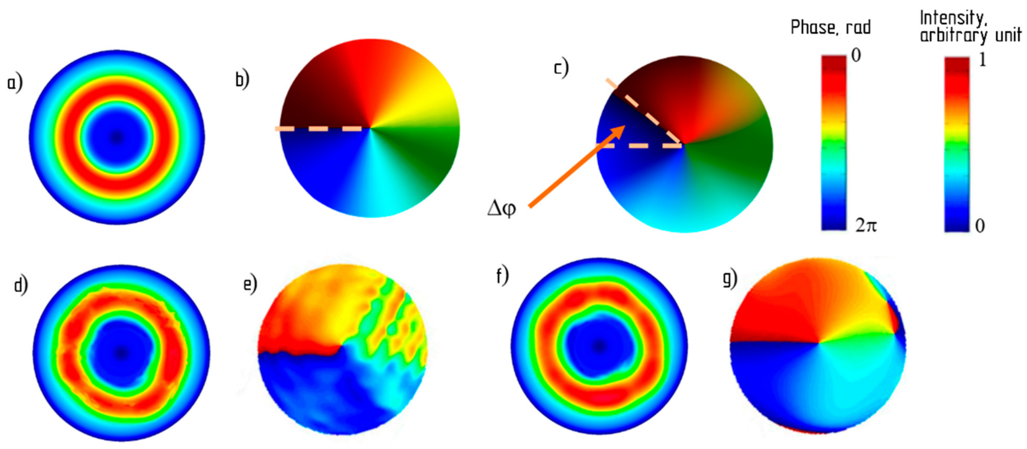
Figure 5 shows the results of computer simulation of the intensity and phase for radiation at the output of the V-FBG using the complex-valued expression (9), plotted for a time equal to one radiation period (i.e., at a length equal to the radiation wavelength). When performing calculations for
ZB (in the transition from
E to
I), the value
λcr, H01 = 1.64·
rco, corresponding to
LP11, was used. The radius
rco was chosen equal to 20 μm, which approximately corresponds to special optical fibers providing a few-mode regime in the telecommunication C-band (for example, it can be a step-index FMF developed by the OFS company [
35]).
Based on the calculations, it can be seen that without taking into account the temporal effect associated with the interaction of lasers, i.e., at
= 1, as well as when the radiation wavelength
λ0 (in vacuum) and the parameter
correspond (and at
g(
z) = 1), a first-order OAM was obtained,
Figure 5a,b. But when the mismatch
λ0 ≠
occurs, “overtwisting” (for
λ0 <
or “undertwisting”
λ0 >
) of the vortex is obtained,
Figure 5c, which, perhaps, is not critical, but may turn out to be a destructive factor in the case of using several OAM-orders communication line—the components of the group signal are no longer orthogonal. Obviously, Δ
φ is the more significant, the greater is the difference between
λ1 and
λ2. Additional inclusion of dependence
leads to the fact that the vortex ceases to be ideal, noticeable distortions appear,
Figure 5d,e, which will also significantly reduce the efficiency of using such a signal (here it should be taken into account that even in the case of a single source of radiation on a fiber-optic communication line, the intensity of the input signal for the V-FBG in practice cannot be absolutely stable. The identified distortion factor is therefore inevitable). To a certain extent, the situation can be improved by using the V-FBG apodization: thus, at
g(
z) = sin
2z, we obtain a decrease in distortions—
Figure 5f,g. Moreover, the twist angle Δ
φ is also slightly reduced. By enumerating various functions
g(
z) with subsequent analysis of the degree of the vortex distortion μ according to the standard deviation criterion, it was possible to establish the following: the vortex distortion largely depends on the maximum value
reached in the studied interval, which should be approximately in the range of 0.5…0.7.
Figure 6 shows a typical form of such dependences, and the resulting values of the twist angle for Δ
λ = 0.75 nm. The calculations lead to the following conclusion: proceeding from the fact that the distortions of the vortex for the considered segment (the principle of obtaining a two-frequency optical signal; the value of Δ
λ) are twofold: the appearance of both μ and Δ
φ, then the value of
ζ should be approximately chosen from range ≅ 0.7…1.1.
Introduction of chirping, i.e., for
≠ 0, additionally decreases Δ
φ due to the fact that the effective reflection (and “twisting”) of the OAM at the adjacent wavelength occurs in the region closer to the resonance one. So, if the V-FBG chirp is uniform, i.e., in one part of the grating
≅
λ1, and in the other
≅
λ2, then
. But the analysis of Δ
φ depending on the different values of
showed the following: the smallest twisting is achieved with a slightly different chirp multiplier than that presented here. So,
Figure 7 shows a graph
from which it can be established that the best value of
in this sense corresponds approximately to
.
Figure 8 shows the bulk profile of the refractive index of a vortex periodic structure, which is optimal from the point of view of minimizing distortions of a two-frequency vortex signal.

 ,
, 


