Research on the Ablation Characteristics and Thermomechanical Coupling Matching of Continuous-Wave/Pulsed Combined Lasers

Abstract
:1. Introduction
2. Experimental System
3. Results
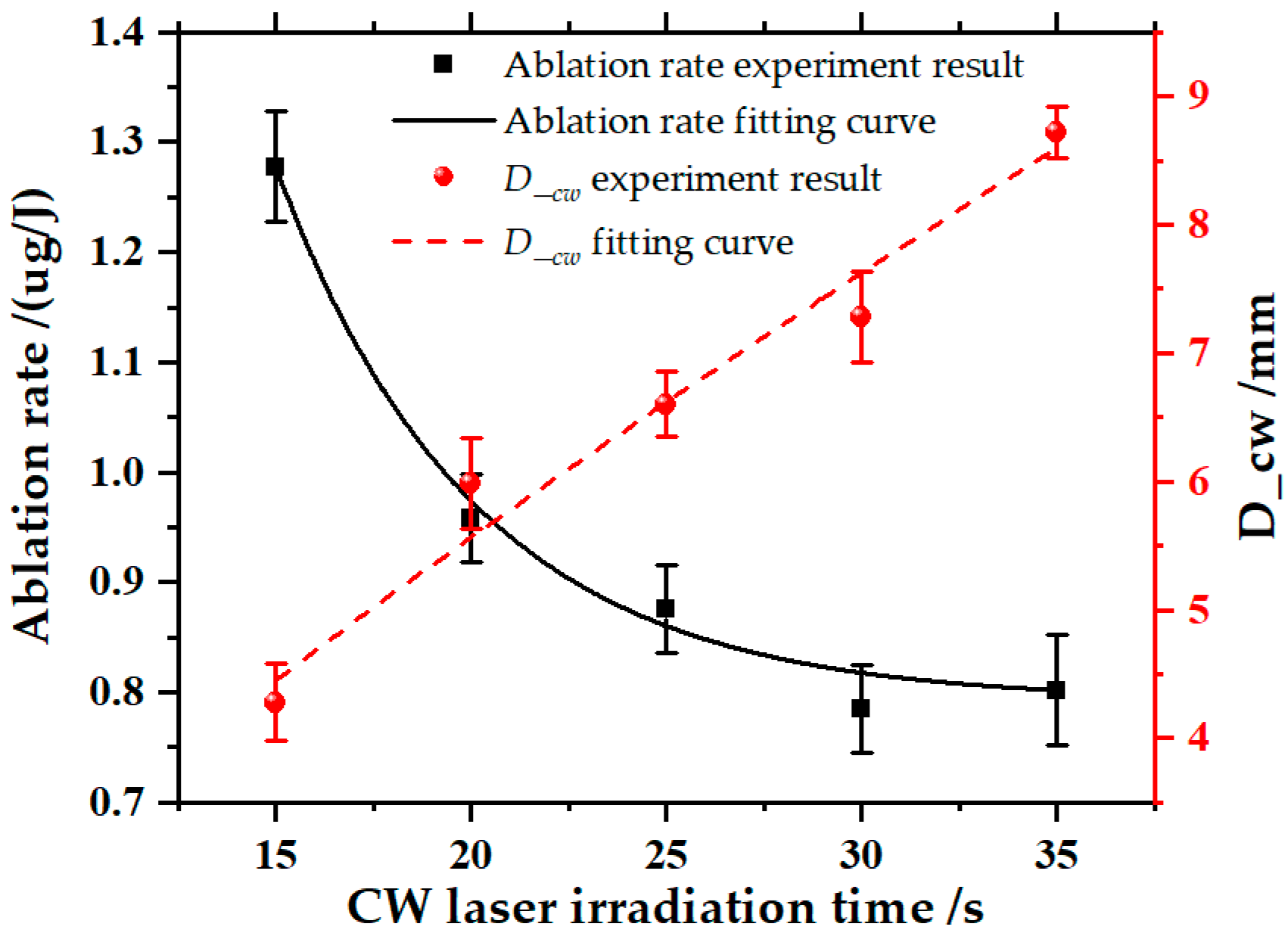
3.1. CW Laser
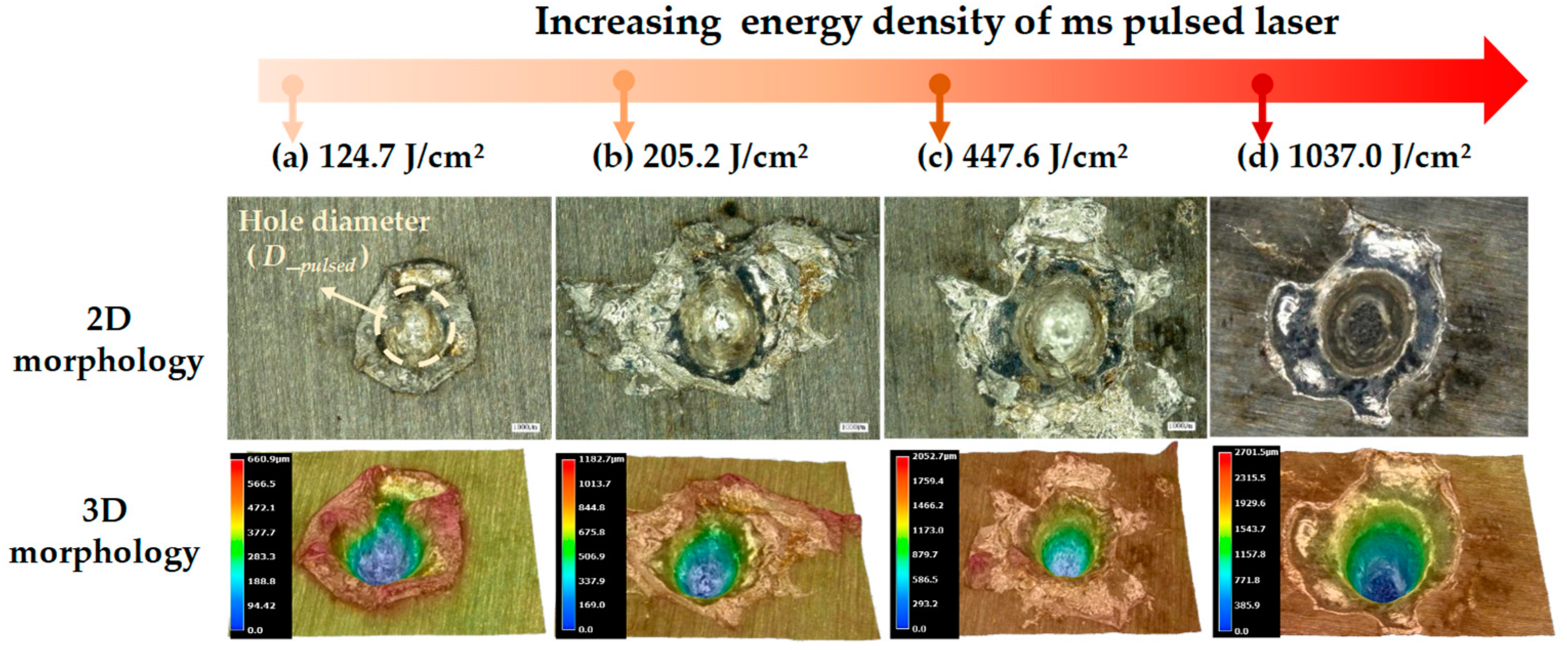
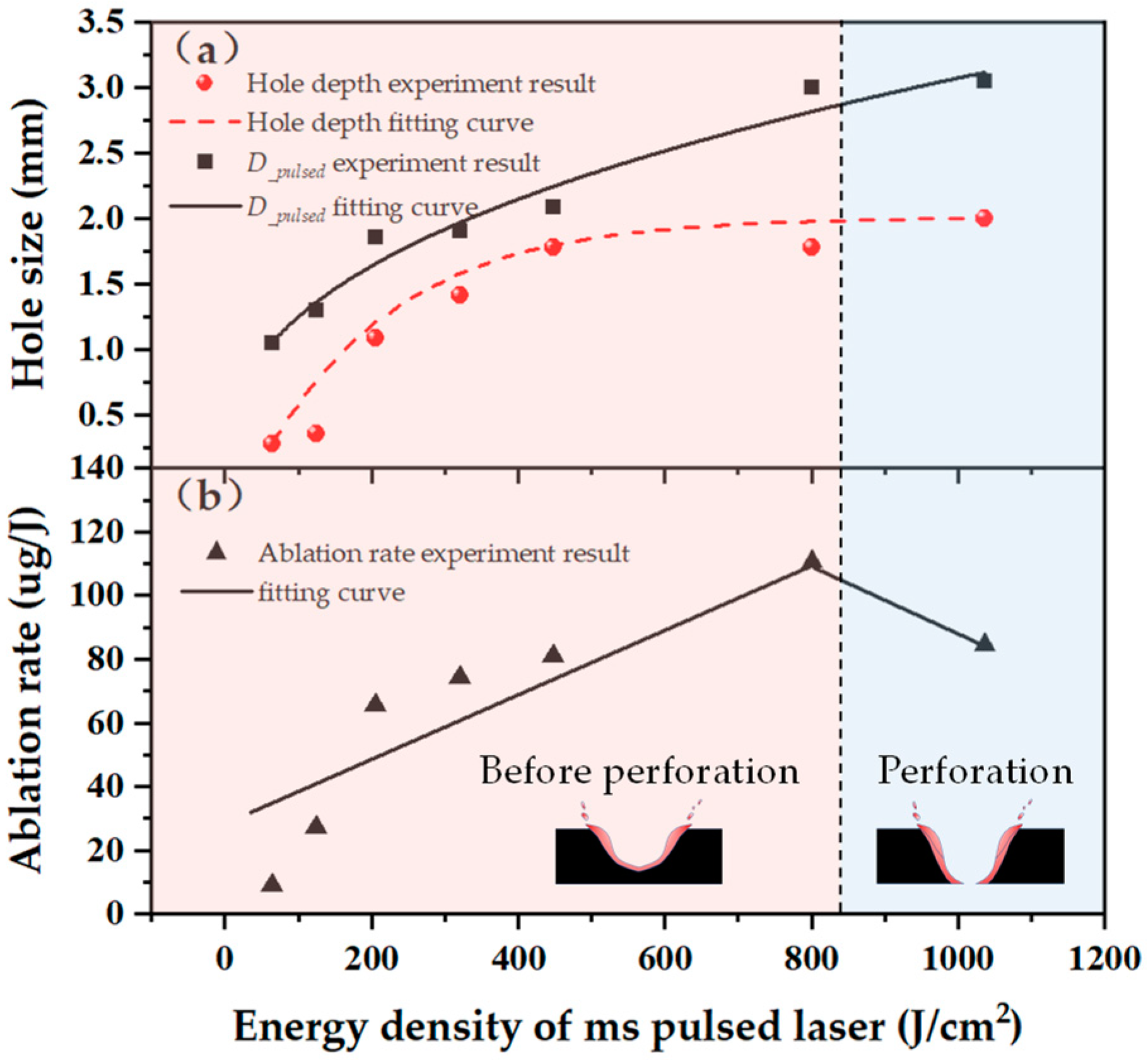
3.2. Ms Pulsed Laser
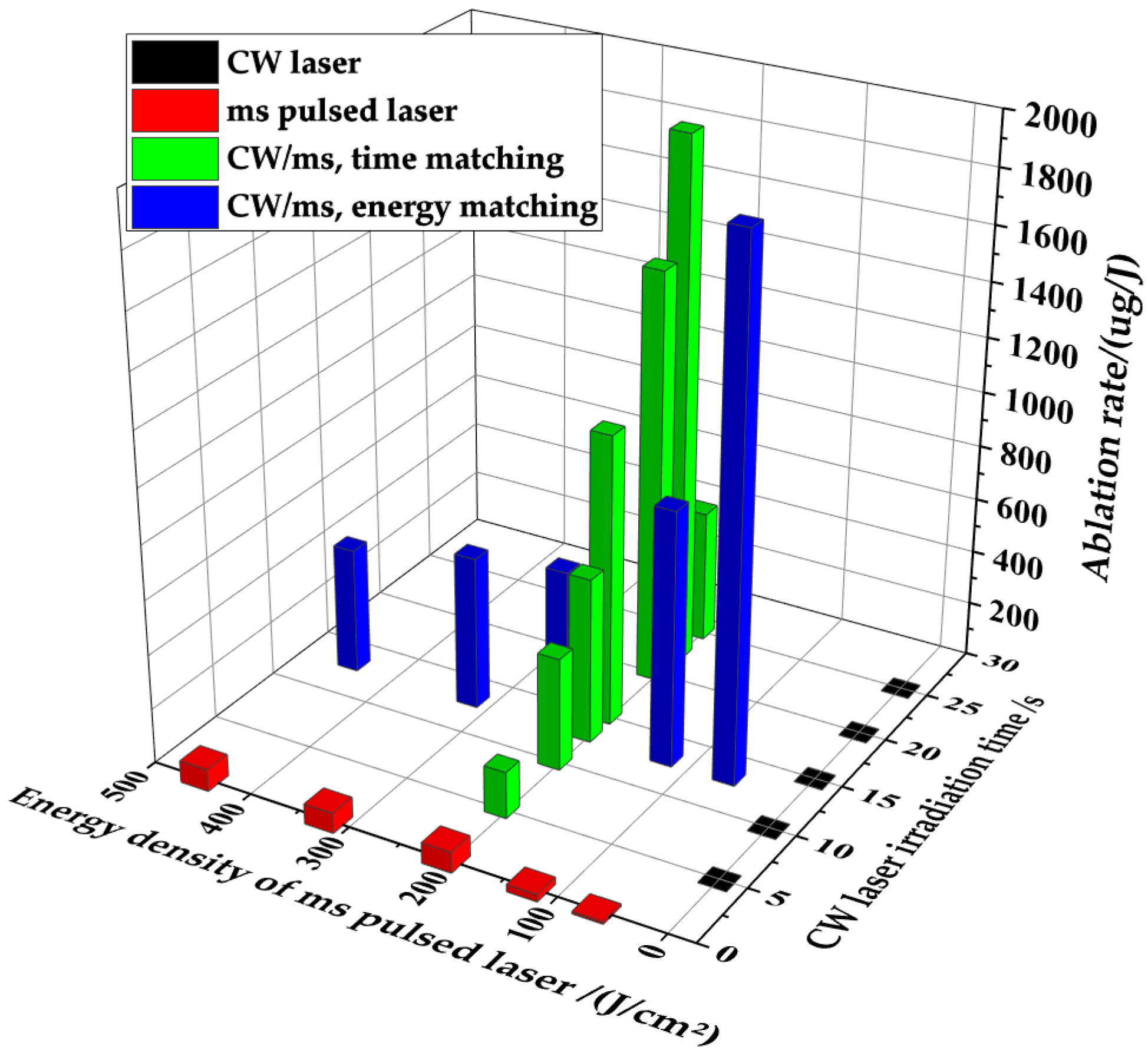
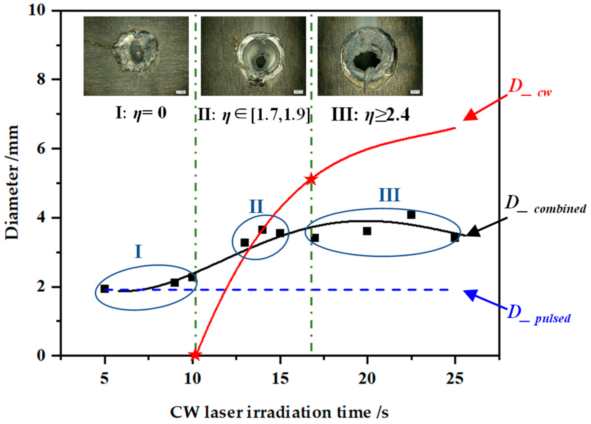
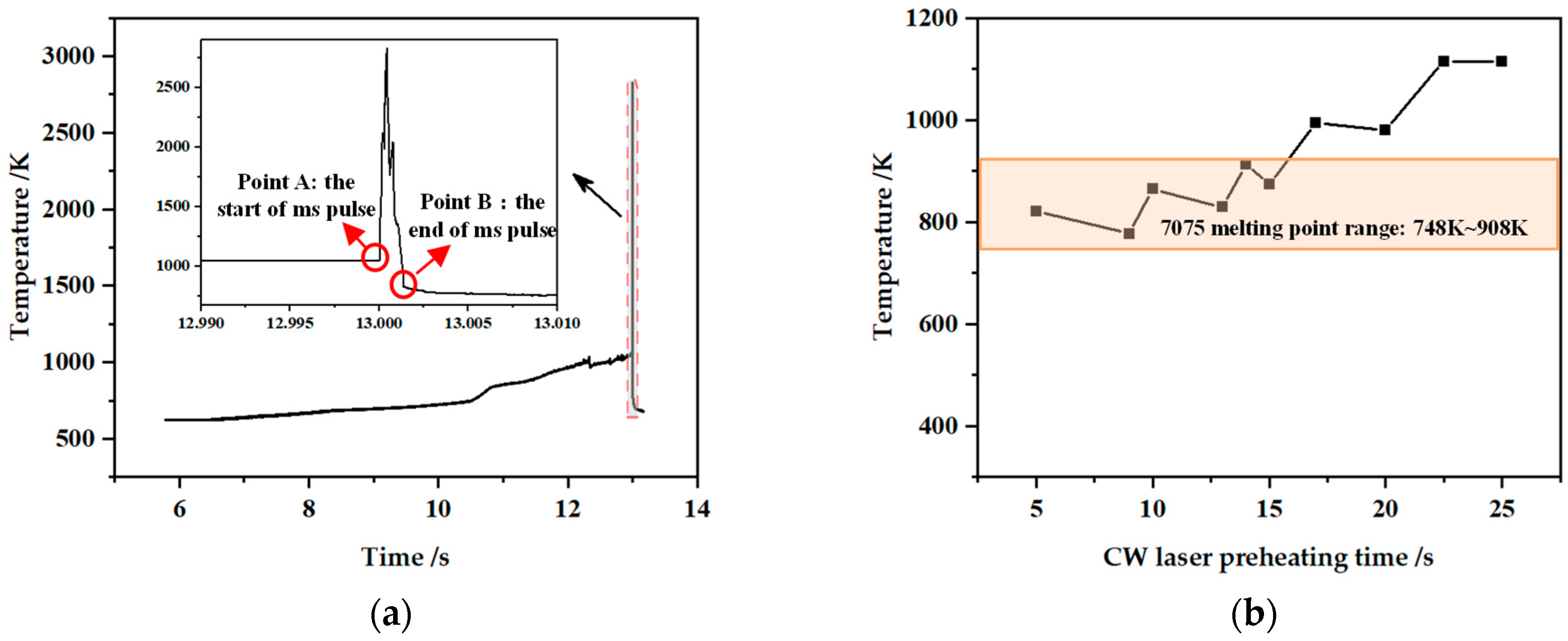
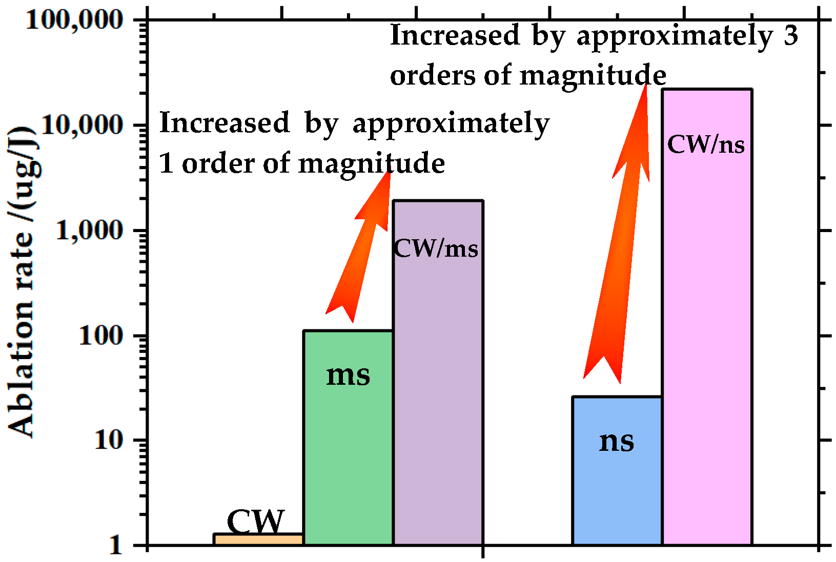
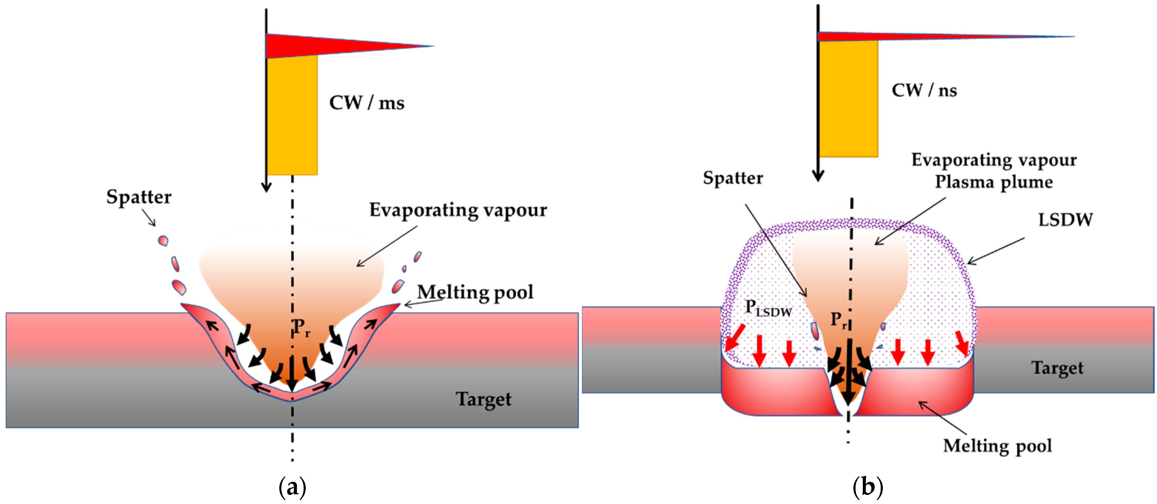
3.3. CW/ms Combined Laser
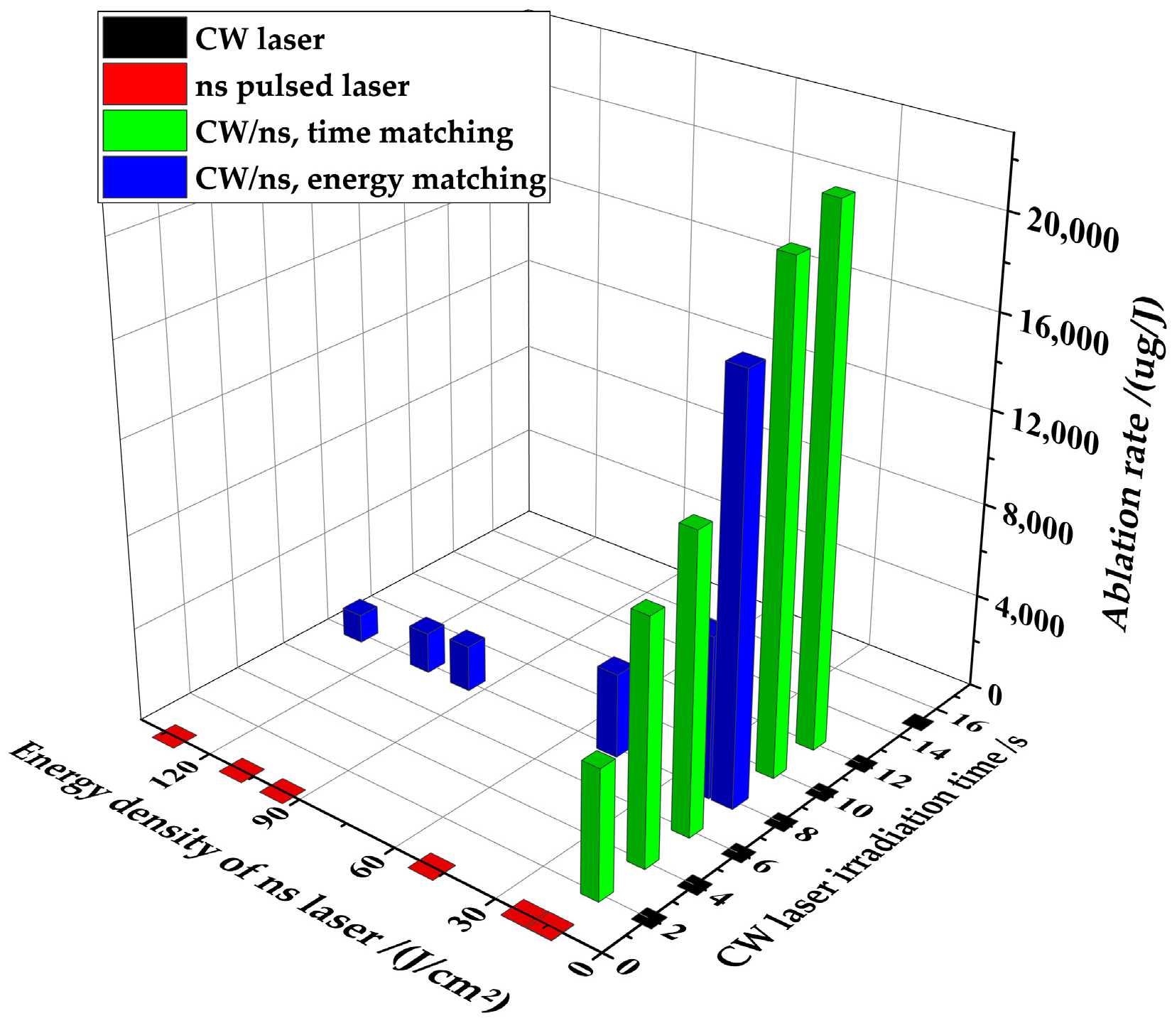
3.4. CW/ns Combined Laser
4. Discussion
5. Conclusions
Author Contributions
Funding
Informed Consent Statement
Data Availability Statement
Conflicts of Interest
References
- Fox, J.A. A method for improving continuous wave laser penetration of metal targets. Appl. Phys. Lett. 2008, 26, 682–684. [Google Scholar] [CrossRef]
- Robin, J.E.; Nordin, P. Improved cw laser penetration of solids using a superimposed pulsed laser. Appl. Phys. Lett. 2008, 29, 3–5. [Google Scholar] [CrossRef]
- Towle, L.C.; McKay, J.A.; Schriempf, J.T. The penetration of thin metal plates by combined cw and pulsedlaser radiation. J. Appl. Phys. 1979, 50, 4391–4393. [Google Scholar] [CrossRef]
- Ding, Y.; Yang, L.; Hong, M. Enhancement of pulsed laser ablation assisted with continuous wave laser irradiation. Sci. China Phys. Mech. Astron. 2019, 62, 34211. [Google Scholar] [CrossRef]
- Khalil, A.A.I.; Hafez, A.I.; Elgohary, M.E.; Morsy, M.A. Tungsten ion source under double-pulse laser ablation system. Chin. Phys. B 2017, 26, 095201. [Google Scholar] [CrossRef]
- Kasuga, M.; Sano, T.; Hirose, A. Grain refining in weld metal using short-pulsed laser ablation during CW laser welding of 2024-T3 aluminum alloy. Int. J. Extrem. Manuf. 2019, 1, 045003. [Google Scholar] [CrossRef]
- Hess, A.; Weber, R.; Heider, A.; Graf, T.J.P.P. Forced deep-penetration welding with low-power second-harmonic assistance of cw copper welding with 1 μm wavelength. Phys. Procedia 2010, 5, 29–36. [Google Scholar] [CrossRef]
- Hess, A.; Schuster, R.; Heider, A.; Weber, R.; Graf, T.J.P.P. Continuous wave laser welding of copper with combined beams at wavelengths of 1030 nm and of 515 nm. Phys. Procedia 2011, 12, 88–94. [Google Scholar] [CrossRef]
- Jia, X.; Chen, Y.; Liu, L.; Wang, C. Combined pulse laser: Reliable tool for high-quality, high-efficiency material processing. Opt. Laser Technol. 2022, 153, 108209. [Google Scholar] [CrossRef]
- Zeng, J.; Lu, Q.; Shu, B.; Xu, X.; Liu, Z. Combined damage effect of GaAs irradiated by 1.06 μm CW and pulse laser. High Power Laser Part. Beams 1998, 10, 217–220. [Google Scholar]
- Yong, C.; Mengzhen, Z.; Yunfeng, M.; Jingsong, W.; Xu, L.; Fangzheng, D.; Chaoyong, T.; Xia, C.; Yanlong, G.; Hua, C. Mechanism and effects of complex laser ablation. Infrared Laser Eng. 2016, 45, 1105005. [Google Scholar] [CrossRef]
- Yong, C.; Yanlong, G.; Huang, T. Development trend of tactical laser weapons. Laser Optoelectron. Prog. 2016, 53, 110004. [Google Scholar]
- Jia, X.; Zhang, Y.; Chen, Y.; Wang, H.; Zhu, G.; Zhu, X. Combined pulsed laser drilling of metal by continuous wave laser and nanosecond pulse train. Int. J. Adv. Manuf. Technol. 2019, 104, 1269–1274. [Google Scholar] [CrossRef]
- Luguang, J.; Guomin, Z.; Minsun, C. Investigation on the irradiation effects of Q235 steel targets by combined laser. Infrared Laser Eng. 2011, 40, 848–852. [Google Scholar]
- Jia, X.; Chen, Y.; Zhu, G.; Wang, H.; Aleksei, K.; Zhu, X. Experimental study on the optimum matching of CW-nanosecond combined pulse laser drilling. Appl. Opt. 2019, 58, 9105–9111. [Google Scholar] [CrossRef]
- Xiao, J.; He, H.; Xia, H.; Jia, J. Temperature flied simulation on aluminium alloy irradiated by long pulsed laser and continuous wave laser. Chin. J. Lasers 2012, 39, 1103002. [Google Scholar] [CrossRef]
- Xiao, J.; He, H.; Xia, H. Stress simulation of aluminium alloy irradiated by long pulsed laser and continuous wave laser. Chin. J. Lasers 2013, 40, 0803009. [Google Scholar] [CrossRef]
- Lehane, C.; Kwok, H.S. Enhanced drilling using a dual-pulse Nd: YAG laser. Appl. Phys. A 2001, 73, 45–48. [Google Scholar] [CrossRef]
- Editorial Board of the Practical Handbook of Engineering Materials. Practical Handbook of Engineering Materials (Volume 3): Aluminium Magnesium Alloys; China Standard Press: Beijing, China, 2002. [Google Scholar]
- Zhang, K. Phase transition speed research of metal material at laser irradiation medium strength. Acta Phys. Sin. 2004, 53, 1815–1819. [Google Scholar] [CrossRef]
- Yan, Z.; Mei, X.; Wang, W.; Pan, A.; Lin, Q.; Huang, C. Numerical simulation on nanosecond laser ablation of titanium considering plasma shield and evaporation-affected surface thermocapillary convection. Opt. Commun. 2019, 453, 124384. [Google Scholar] [CrossRef]
- Zhang, G.; Zhu, B.; Zou, J.; Wu, Q.; Xiao, R. Correlation between the spatters and evaporation vapor on the front keyhole wall during fiber laser keyhole welding. J. Mater. Res. Technol. 2020, 9, 15143–15152. [Google Scholar] [CrossRef]
- Heyan, G.; Xing, J.; Lan, L.; Meng, Y.; Ying, W. Effect of energy density on material migration mechanism in millisecond laser ablation of aluminum target. Infrared Laser Eng. 2021, 50, 20210264. [Google Scholar]
- Zhang, Y.; Lu, X.; Zhou, M.-L.; Lin, X.-X.; Zheng, Z.-Y.; Li, Y.-T.; Zhang, J. Laser propulsion with a high specific impulse using a thin film propellant. Chin. Phys. B 2011, 20, 087901. [Google Scholar] [CrossRef]
- Wang, L.; Zhang, Y.; Yan, W. Evaporation model for keyhole dynamics during additive manufacturing of metal. Phys. Rev. Appl. 2020, 14, 064039. [Google Scholar] [CrossRef]
- Qin, Y.; Förster, D.J.; Weber, R.; Graf, T.; Yang, S. Numerical study of the dynamics of the hole formation during drilling with combined ms and ns laser pulses. Opt. Laser Technol. 2019, 112, 8–19. [Google Scholar] [CrossRef]


| Parameter | CW Laser | ms Pulsed Laser | ns Pulsed Laser |
|---|---|---|---|
| Wavelength | 1.08 μm | 1.06 μm | 1.06 μm |
| Power | 1000 W (max) | – | – |
| Energy @Pulse duration | – | 500 J @1 ms | 10 J @10 ns |
| Laser divergence angle | 2 mard | 2.5 mard | 2 mard |
| Spot profile | flat-top beam | flat-top beam | flat-top beam |
 |  |  |
| Temperature | Specific Heat Capacity | Density | Thermal Conductivity | Melting Point |
|---|---|---|---|---|
| 373 K | 900 J·(kg K)−1 | 2775 kg·m−3 | 142 W·(m K)−1 | 748~908 K |
Publisher’s Note: MDPI stays neutral with regard to jurisdictional claims in published maps and institutional affiliations. |
© 2022 by the authors. Licensee MDPI, Basel, Switzerland. This article is an open access article distributed under the terms and conditions of the Creative Commons Attribution (CC BY) license (https://creativecommons.org/licenses/by/4.0/).
Share and Cite
Xiao, J.; Feng, G.; Ren, G.; Han, J.; Xia, H.; Wang, Y.; Deng, W.; Chen, T.; Guo, R. Research on the Ablation Characteristics and Thermomechanical Coupling Matching of Continuous-Wave/Pulsed Combined Lasers. Photonics 2022, 9, 679. https://doi.org/10.3390/photonics9100679
Xiao J, Feng G, Ren G, Han J, Xia H, Wang Y, Deng W, Chen T, Guo R. Research on the Ablation Characteristics and Thermomechanical Coupling Matching of Continuous-Wave/Pulsed Combined Lasers. Photonics. 2022; 9(10):679. https://doi.org/10.3390/photonics9100679
Chicago/Turabian StyleXiao, Jing, Guoying Feng, Gang Ren, Jinhua Han, Huijun Xia, You Wang, Wantao Deng, Tianyu Chen, and Rongjun Guo. 2022. "Research on the Ablation Characteristics and Thermomechanical Coupling Matching of Continuous-Wave/Pulsed Combined Lasers" Photonics 9, no. 10: 679. https://doi.org/10.3390/photonics9100679
APA StyleXiao, J., Feng, G., Ren, G., Han, J., Xia, H., Wang, Y., Deng, W., Chen, T., & Guo, R. (2022). Research on the Ablation Characteristics and Thermomechanical Coupling Matching of Continuous-Wave/Pulsed Combined Lasers. Photonics, 9(10), 679. https://doi.org/10.3390/photonics9100679