1. Introduction
Optical phased arrays (OPAs) have been actively developed as the key component of laser scanners for solid-state light detection and ranging (LiDAR) [
1,
2,
3] and off-chip optical wireless transmission [
4,
5]. Silicon-based OPAs have been intensively studied because they offer compact integration, low power consumption, stable operation and low-cost mass production [
3]. For most LiDAR and wireless applications, wide beam steering is required in two-dimensional (2-D) space. To ensure a wide beam-forming range above several tens of degrees with a single beam, the radiator array should be integrated with narrow intervals within a micrometer scale [
6,
7,
8]. Due to this fundamental constraint, originating from the diffraction condition, the 2-D OPA could not meet the wide beam steering requirement because it was hard to integrate many elements, such as a waveguide line, phase controller and radiator in micrometer scales. Thus, the true 2-D OPAs demonstrated beam steering with active phase tuning within a limited range of around 10° in both directions [
9]. To extend the beam steering range, which is limited by the structure of the 2-D OPA, various methods have been proposed to control the longitudinal radiation angle while only employing the one-dimensional (1-D) OPA. For longitudinal beam steering with a 1-D grating radiator array, schemes to control the wavelength [
5,
6,
7,
8] and the effective index of the radiators [
10] have been proposed. Integration of Mx(1xN) arrays with different grating periods [
11] has also been proposed. For transversal steering with a 1-D OPA, the active phase shifters based on thermo-optic and electro-optic effects are used for phase tuning by recalling the phase from the lookup table that stored the pre-measured phase corresponding to the desired steering angle [
6]. Therefore, the size of the lookup table increases in proportion to the number of 1-D grating radiator array elements and resolved points of far-field.
As another efficient method without active phase shifters, a 2-D steering scheme employing the path difference and wavelength control have been demonstrated with a passive silicon-on-insulator (SOI)-based OPA [
12] and a passive silica-based OPA using the arrayed waveguide gratings platform [
13], which can provide a low phase error in the fabricated waveguides. However, as pointed out in references [
12,
13], the beam quality provided by these passive OPAs is very sensitive to the phase error, due to the effective index variation from the fabrication process. Considering that the error range in the effective index provided in the typical SOI fabrication process is about 10
−4, as demonstrated in reference [
14], a new architecture is necessary to compensate for this phase error and to take advantage of the passive beam-steering approach using wavelength tuning based on the compact SOI-based OPA.
In this paper, we demonstrate similar 2-D beam steering using a silicon-based 1-D OPA, but the path-different waveguides are integrated with active phase shifters and present allowable error ranges for passive beam steering using an analysis of the effect of fabrication error. In the current fabrication process of the SOI-based OPAs, the phase error is worse than that in the silica platform. Thus, we employed phase shifters for phase initialization to form a single beam from an as-fabricated OPA chip in which some phase errors were immanent. After the phase initialization, we successfully achieved 2-D beam steering through the wavelength tuning alone. The scheme can minimize the phase initialization process, which is repeated in every step for beam shift in the current Si OPA.
2. Design and Simulation
We first consider the principle of transverse steering using the path difference. When the length of the passive waveguide of each channel is sequentially increased with a path difference of Δ
L, the phase difference
between the channels is given by
, where
is the effective index of the waveguide and
the vacuum wavelength of the input light and the
integer. In a structure where the phase of each channel is well-aligned to form a single beam, the beam can be allocated at the center with a specific wavelength of
. If the wavelength
is varied from
by
, the beam can shift to the transversal direction by
, where
is the pitch of a regular radiator array [
12]. The position can be expressed as:
The wavelength tuning range of
with a 2π (or ±π)-phase shift for full steering in the transversal direction is simply given by:
The steering range with this 2π-phase shift or is the maximum angle attainable with a single beam in the transversal direction, given by = sin−1(λ/r).
Next, we consider the longitudinal beam shift from a grating radiator array. During the transversal steering by the wavelength change, the radiation direction of the beam is also varied in the longitudinal direction, following the Bragg diffraction condition as:
where
is the longitudinal angle from the normal direction,
is the effective index of the Floquet–Bloch mode in the grating,
is the index of the cladding and
is the grating period [
12]. Combining the two effects of the wavelength variation on the transversal and longitudinal directions, after the 2π-phase shift with a wavelength tuning of
, the beam returns to the initial angle in the transversal direction but skips to
+
in the longitudinal direction. The skip angle
is given from the differential of Equation (3) and applied to the small wavelength interval
, as follows:
with
.
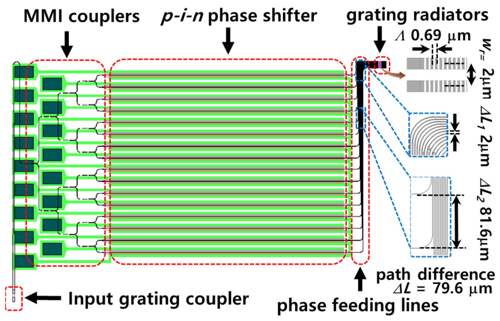
For the experiment, we designed an OPA structure that provided a path difference in the phase-feeding region between the phase shifters and grating radiators, as shown in
Figure 1. The OPA was designed with 1 × 16 channels, consisting of an input grating coupler, 4 stages of a 1 × 2 multi-mode interferometer (MMI) splitter, electro-optic
p-i-n phase shifters and grating radiators. The input grating coupler was designed with a grating period of 620 nm, etch depth of 70 nm and a grating width of 10 μm in 220 nm thick top silicon on a SOI platform, and coupled with a fiber-tailed 1550 nm light source. To split the input light into 16 channels, four stages of 1 × 2 MMI were configured. Using the multi stages of the MMI splitters, the channels were paned-out to the phase shifters with a pitch of 81.6 μm. The width and length of the MMI were determined to be 3 μm and 7.4 μm in consideration of the minimum dimension and loss. The electro-optic phase shifters were designed as a
p-i-n junctions, where the p-and n-doped regions were placed on both sides of the intrinsic region containing each waveguide core. The waveguide was designed with a width of 500 nm, a height of 220 nm and a slab height of 70 nm. The p-and n-doped regions were formed on the slab. In addition, a 1 × 16 grating radiator array, which determines the beam steering angle, was designed with a grating period (
) of 690 nm and a grating pitch (
r) of 2 μm. More detailed structures of the elements were reported in our previous work [
11,
15], except for the phase-feeding region. The phase-feeding lines were designed with parallel turning lines by a right angle to reach the compactly integrated radiator array, as illustrated in the bottom right of
Figure 1. The bending radius was fixed at 20 μm. In such a fan-in structure, path differences occur in the regions of
L1 before reaching the bending point and
L2 after passing the bending point so that
L =
L2 −
L1.
Figure 2 shows the simulated results of the beam steering performances obtained from core elements, including only the phase-feeding lines and the radiators designed above. The 2-D beam steering performance was simulated using a Lumerical FDTD simulation. As the initial condition, equiphased lights were incident to each phase-feeding line. When the wavelength of light varied by an amount of 90 nm from 1520.0 nm for a phase difference
L = 79.6 μm, the beam traces were almost linear along the transversal direction, but they were slightly inclined to the longitudinal direction, as shown in
Figure 2a. The inclined traces appeared because
and
were simultaneously varied when λ changed, as suggested in Equations (1) and (3). At every 2π-phase shift,
was jumped by
, as expected in Equation (4).
Figure 2b shows far-field patterns corresponding to each of the three points on the first and last full traces, with a 2π phase shift in
Figure 2a. The middle figures show a single spot near
= 0° and the left and right figures show two spots indicating the ±π-phase-shifted state. These spots are shifted, with an increasing wavelength, toward a normal direction in the longitudinal direction. The two spots that split at the ±π-phase-shifted states have slightly different
positions. In these two spots, the newly appeared spot takes over the new
position to start as the main beam at the next transversal steering.
Figure 3. shows the skip angle of
in the longitudinal direction, calculated from the analytical Equations (2) and (4) for
with variation of the path difference in the phase-feeding lines. A numerically simulated value of
for Δ
L = 79.6 μm, indicated in
Figure 2a and by red dot in
Figure 3, agrees well with the calculated value using the simple analytical equations. The result in
Figure 3 also indicates that Δ
L should be increased to reduce the discrete variation of the longitudinal steering angle.
3. Fabrication and Characterization
The OPA was fabricated on an 8-inch SOI wafer with a top silicon layer of 220 nm and a buried oxide layer of 2 μm using CMOS compatible processes. A KrF scanner with a 248 nm wavelength laser was used for the lithography. The detailed process for doping and etching, and the characterization method are described elsewhere [
10,
15].
To observe the far field pattern, the Fourier imaging setup was used with an infrared camera, two tube lenses and a microscope objective with NA 0.65 [
10]. This NA can cover the image within about ±40° in the transversal and longitudinal directions from the center. The resolution of the beam shape was about 0.4° in our setup, when considering the pixel size of the IR camera. Prior to the beam steering operation, phase initialization was performed to control the voltages applied to the phase shifters. To form clear beams at the regular diffraction positions, we used the hill-climbing algorithm [
10]. In the algorithm, each channel was assigned a random starting phase and a reference camera image was taken. Next, a given channel sequentially took several closely spaced drive voltages in a phase shifter and each camera image was captured. Each of these camera images yielded a figure of merit that was defined as the power in the desired angle divided by the power at other angles. Based on these data, the algorithm determined how far and in which direction to step the drive voltage on the given channel, and it then proceeded to the next channel. In our program, it took 80 iterations for all the channels to obtain a clear single beam [
15].
Figure 4 shows the experimental results for the process of beamforming to make the single beam. Initially, the far-field pattern was spatially widespread within the range of the field over the view, as in
Figure 4a(A). It was caused by the fluctuation of the optical path length of each channel from the light source to the radiator, which was induced by fabrication errors, and which is covered in detail later in this section. After the initialization process using the phase shifters in sequence, the dispersed beam was eventually gathered into the single beam with a transversal divergence angle of about 3°, and a side lobe level (SLL) of about 10 dB, as shown in
Figure 4a(D) and
Figure 4b(D).
Figure 5 shows the experimental results of beam steering with the wavelength control obtained from the sample after the phase initialization. We used Keysight’s 81940A tunable laser module for the wavelength control from 1520 nm to 1610 nm. The phase initialization was performed at a starting position with the beam corresponding to the +π-phased state with the shortest wavelength (1520.0 nm) forming two spots, as marked by Δ in
Figure 5a. We then varied the wavelength of input light.
Figure 5a shows the beam traces observed while the wavelength was increased to 1610.0 nm with an interval of 0.1 nm. The steered ranges in the transversal/longitudinal directions (
) are about 46°/12° and these data match the simulated results seen in
Figure 2a well. However, the observed beam positions are somewhat irregularly shifted in the transversal direction. Moreover, in the longitudinal direction, the skip angles are distributed irregularly in a range of 0.6~1.23°, unlike in the simulation. This result might be due to the nonuniformity of fabricated waveguides and the relatively rough resolution of the IR camera we used.
In order to investigate the variation of the beam quality during 2-D steering, we measured the SLL and the divergence angles of the main beam. The SLL was determined by the ratio of the peak intensities between the main diffraction lobes (one or two beams) and another side lobe showing the highest peak. The divergence angle was determined by the full-width half maximum of the peak intensity of the main lobe.
Figure 5c shows the variation of the SLL observed while the wavelength was increased with a fine interval of 0.01 nm after the one-time phase initialization at the starting wavelength. The SLL changes may be periodically changed. The minimum points in each period corresponded to every ±π-phase-shifted state, where two main beams appeared in the lens aperture. This trend may have originated from an inherent diffraction phenomenon of the phased array, namely, the main diffraction power is evenly shared between two beams in the ±π-phased state. However, the maximum points in each period did not match the 0π-phased state, which was expected from the diffraction phenomenon. This is an interesting trend to be studied further. Nevertheless, the lowest values of the SLL were maintained at a level almost above the initial value of 8 dB, indicating that there was no degradation in the beam intensity during the full 2-D steering. Considering the beam divergence, shown in
Figure 5c, both the transversal and the longitudinal divergence angles were slightly widened overall, while the wavelength increased. An interesting point is that, in the transversal divergence, some abrupt degradation occurred almost every time the beam was switched from the -π-phased state to the +π-phased state, and the divergence was, overall, recovered during the 2π steering. In the longitudinal divergence, such a trend did not appear. Even though such degradations appeared, the divergence angles did not exceed ±25% of the level of the initial values of 2.9°/4.6° in the transversal/longitudinal direction.
In
Figure 5d, we investigated the effect of realignment of the phase on the SLL. The data without phase realignment were obtained only from one-time phase initialization at the start of the beam steering, as shown in
Figure 5a–c, and they were compared with the data obtained after the realignment of the phase at each beam position, i.e., each wavelength. The results show that two data lines approach the 1 dB level. The far field patterns represented in
Figure 5e, for each of the three positions on the first and last transversal steering (with 2π phase shift) traces in
Figure 5a, confirm the maintenance of clear beams during full steering. This result indicates the possibility of full 2-D beam steering with wavelength tuning alone, without a complex phase realignment process in our scheme.
We suggest that the spatial dispersion of the beam pattern with single beamforming and beam steering, which is observed in
Figure 4 and
Figure 5, is caused by nonuniformity in the effective index of each waveguide channel; that phenomenon fundamentally originated from the variation of waveguide conditions, such as the width, thickness, etched state, doping condition and refractive index of the material.
Here, we first consider how single beamforming and steering are sensitively affected by the variation of the effective index. The total wavenumber in the net distance
L of the waveguide is given by
= 2π
L/λ where
is the effective index. To shift the beam with an angle
by phase control, the required phase difference between each channel is
where
is the maximum steering angle retainable in the transversal direction. Thus, to supply the phase with this difference to each channel, the fluctuation of the wavenumber difference between neighboring waveguides should be controlled within the following range:
where
i denotes the
ith channel and
indicates the fluctuation from the ideally assigned wavenumber to the channel at channel
. We assumed here that the fluctuation
of each channel should be smaller than at least a half of the phase difference
between channels. If we supply the phase difference
with a fixed λ and
L, without the phase shifter, the allowable range in the fluctuation of the
is very small. For example, to supply
responds to the resolution 1° within the 180° with a one-millimeter phase shift (
L = 1 mm); the required accuracy in the
of each channel is an order of 10
−5 in the ratio to the
. Such accurate control of the uniformity of waveguides is difficult In the current silicon photonic processes, when considering the data on the error range in the effective index
, which is reported as the order of 10
−4 [
14,
16]. In order to form and steer the single beam, the phase shifters should be used to compensate for the variation of
, as proposed in our work.
Next, we consider the possibility of beam steering with wavelength tuning by employing phase shifters. Once the phases are initialized using the phase shifters to form a beam at the center with
for the initial
,
should be set with integer values in ideal waveguides. However, in real waveguides, the
values may deviate with
from the integer values due to the fluctuation of
as:
If
is sufficiently lower than one, i.e.,
the transversal steering is possible with wavelength tuning alone, without serious beam distortion.
From Equations (5) and (7), we can represent two criteria for the allowable ranges of the
as:
Here,
and
are the criteria for the beam steering by wavelength tuning without, and with, phase initialization. Since we use the wavelengths
≈
,
is smaller than
. This relation indicates that even if the fluctuation of the effective index is higher than the condition for the complete passive beam steering condition, there is a possible range for the passive beam steering if the phase initialization is performed first. We expect that our previous work for the silica OPA [
15] satisfied the first criterion and the present work satisfied the second criterion. In the present work, the nonuniformity of the effective index is expected to be within an order of 10
−4, considering the waveguide length and the measured beam quality, which is similar to the results of another study [
14]. In such a case,
is expected to be approximately 0.06 for a waveguide length
L = 1 mm including the
p-i-n phase shifter and it may maintain sufficiently low values, even though the
is varied during full 2-D steering.
Finally, we considered the controllability of the longitudinal beam steering during wavelength tuning. From Equation (3), the variation of the radiation direction by the wavelength change in a single grating radiator can be given by:
where
is the effective index of the grating radiator. The approximation is valid at a small angle of
. Due to fabrication errors, if some fluctuation of
and
intervenes in the radiator array, the shifted radiation angle
by the wavelength change
may fluctuate as:
where
denotes the fluctuation of relevant terms, as denoted in Equations (5)–(9). Thus, the fluctuation of
that appeared in
Figure 5a might be due to the
and
terms, and it implies that these two error terms should be reduced further for accurate control of the longitudinal radiation angles.
Based on our estimation described above, if the uniformities of
in the waveguides and radiators can be controlled by one order of magnitude over the present processes, we expect that the regularity in the beam shift can be assured to maintain the overall beam quality even in larger OPA structures. Furthermore, if the thermo-optic tunable grating radiator [
11] is applied in the OPA structure of
Figure 1, continuous steering can be achieved in the longitudinal direction with a small thermal tuning
covering a skip range of δ
. Since the single beam is maintained during the thermal tuning [
11], this scheme can be a practical solution to attain continuous 2-D steering with a simplified phase initialization process.

 ,
, 