Article

Design of Matching Imaging on Agile Satellite with Wide-Swath Whiskbroom Payloads along the Coastal Zone

1
Changchun Institute of Optics, Fine Mechanics and Physics, Chinese Academy of Sciences, Changchun 130033, China
2
University of Chinese Academy of Sciences, Beijing 100049, China
3
Key Laboratory of Space-Based Dynamic Rapid Optical Imaging Technology, Chinese Academy of Sciences, Changchun 130033, China
*
Author to whom correspondence should be addressed.
Photonics 2022, 9(12), 930; https://doi.org/10.3390/photonics9120930
Submission received: 3 October 2022 / Revised: 9 November 2022 / Accepted: 22 November 2022 / Published: 2 December 2022

Abstract

:
The non-linearly curved coastal zone is very long and wide. The traditional satellite can’t cover the whole coastal zone in a single scan. So, the method of matching imaging combining the adjustment of satellite attitude and the scanning of the swing mirror are proposed. Firstly, based on the position of feature points of the coastal zone, the attitude when the optical axis of the satellite always points to the feature points is calculated. According to the width of the sea and land on both sides of the coastline, the parameters of the swing mirror of wide-swath whiskbroom payloads are analyzed. Secondly, the velocity vector model considering time-varying satellite attitude and the dynamic scanning of the swing mirror is constructed. The schemes of matching imaging such as adjustments of yaw angle and detector are developed. Finally, the precise experiment is designed to verify the correctness of the matching imaging. The experimental results show that the resolution of the matching imaging is less than 1 pixel and its modulation transfer function (MTF) is greater than the human eye’s minimum MTF of 0.026. The method of matching imaging using the adjustment of satellite attitude and the scanning of the swing mirror can realize wide imaging along the coastline and improve the temporal resolution at the same time.

1. Introduction

The coastal zone is not only the area with the most active interaction among land, ocean and atmosphere, but also the area with the most frequent human economic activities in the world. 2/3 of the large and medium-sized cities in the world are concentrated along the coastal zone, with 60% of the population and a developed economy. In the coastal zone, 8% of the earth’s surface provides 28% of the world’s biological production and owns 90% of the global fishery industry. The total length of the global coastal zone is 504,000 km, with nonlinear bending and extension, including a coverage width of ±100 km extending from coastline to continental and oceanic. The coastal zone generally presents the characteristics of length, width and curvature. Its biological species are complex and diverse [1,2].
Satellites can quickly obtain comprehensive data on the coastal environment, ecosystems, landforms, coastline conditions, water quality, biological resources, natural disasters, and human activities [3,4,5,6]. It has become an effective tool in regularly monitoring coastal resources and environmental changes. At present, there are two main types of satellites used in observation of coastal zone: wide-coverage push-broom satellite and agile high-resolution satellite [7]. The wide-coverage push-broom satellite has low resolution. For example, the resolution of SDGSAT-1 [8] is 30 m. It uses a one-dimensional swing mirror to expand coverage, which can obtain thermal infrared images of 300 km. But it can only expand the coverage of the nadir area. The coverage of agile high-resolution satellites is smaller. However, it can search for non-nadir targets by attitude adjustment, such as WorldView [9,10,11], STOP5/6 [12,13], Pleiades [14,15], etc. In this way, the fast revisiting of fine objects can be achieved by agile satellites. What’s more, image stitching [16] can be used in agile high-resolution satellites to expand coverage.
Although the wide-coverage push-broom satellite has a large imaging range, it can only image the symmetrical areas on both sides of the satellite’s nadir point. The coastal zone is the boundary between the ocean and the land, which shows an irregular curved distribution. It is difficult to match with the image trajectory of wide-coverage push-broom satellite [17]. Only part of the coastal zone will be covered by the wide-coverage push-broom satellite at single scanning. However, if agile high-resolution satellite and image stitching methods are used in imaging the coastal zone, the temporal resolution will be low. It is impossible to quickly cover both water and land on the sides of the coastline.
In addition, both wide-coverage push-broom satellites and agile high-resolution satellites have high-dynamic properties [18], which leads to time-varying and aeolotropic properties of velocity vectors on the image plane. The velocity on the image plane does not match the detector’s imaging direction, causing image degradation [19]. The velocity vector matching is difficult in those complex imaging modes [20]. In 2020, Xu [21] et al. studied velocity vector on the image surface of a space camera for dynamic circular scanning, and carried out numerical and image simulation. In the same year, based on this dynamic imaging model, Wang [22,23] et al. explored the degradation of the image caused by rotation of the image plane. In 2021, Han [24] et al. analyzed the distribution characteristics of velocity vector when satellite scanning Antarctica by combining the characteristics of polar target distribution. In addition, the velocity vector is also applied to approve image quality, one of which is the image compensation method. For example, Sun [25] et al. proposed a method of segmental PSF compensation by calculating the velocity vector on the image plane, which effectively corrected the image motion blur of the KZ-1 agile satellite. The other is on-orbit compensation. Li [26] et al. predicted the yaw angle of satellites through the velocity vector, proposed a method to compensate for the average drift angle by adjusting the satellite yaw angle, and then used the image plane adjustment mechanism in the camera to eliminate the residual error. However, these models and compensation methods are all applicable to traditional push-broom It lacks velocity vectors considering satellite attitude adjustment and swing mirror.
To solve the difficulty of the full coverage of the coastal zone at single scanning by the traditional satellite, a new mode is proposed. The mode expands the coverage through the scanning of the swing mirror [27,28] when the agile satellite adjusts the attitude to image along the coastline [29]. However, there will be an enormous mismatch between the velocity and the direction of detector because this new kind of imaging mode has large dynamic maneuvering. The image compensation method is not suitable. So, it is necessary to analyze the distribution of velocity vector on the image plane and develop an on-orbit matching strategy through some hardware adjustment.
The remainder of this article is organized as follows. In Section 2, the attitude of the agile satellites along the coastline is planned, and the maneuver scheme of the swing mirror is introduced. In Section 3, based on the proposed mode of imaging the coastal zone, a velocity vector model is constructed and the corresponding matching strategy is established. In Section 4, experiments are designed to verify the feasibility of the proposed matching imaging. In Section 5, conclusions are summarized.

2. Attitude Adjustment and Swing Mirror Scanning of Agile Satellites Imaging the Coastal Zone

As shown in Figure 1a, in order to cover the width of the coastal zone of 200 km and follow the natural contours of the coastline, it is necessary to adjust the satellite attitude angles and attitude angular velocities during the flight of the satellite, so that the optical axis always points to the extension direction of the coastline. At the same time, based on satellite attitude adjustment, the parameters of the swing mirror are designed in consideration of time, width, and overlap ratio of vertical-orbit coverage, which is shown in Figure 1b. This section introduces the full coverage technology of the coastal zone with both the water and land from two parts: attitude adjustment of agile satellite and seamless imaging of the swing mirror scanning.

2.1. Attitude Adjustment of Agile Satellite

There are two processes for the agile satellite scanning along the coast. One is the push-broom along the orbit. The other is side-swing scanning which is perpendicular to the satellite’s flight direction. In order to ensure the whole coastal zone is within the field of view and attitude performance is optimal, only roll angle φ is adjusted under the condition that the pitch angle remains 0. It is designed to assures that the push-broom trajectory of the agile satellite is consistent with the shape of the coastline during flight.
As shown in Figure 1b, the right-hand Cartesian coordinate system G ( G x , G y , G z ) , called Earth centered fixed coordinate system, is established. Its origin is at the center of the earth. G x axis points to the intersection of the Prime Meridian and Equator. G z points to the North Pole. The positions of feature points in the coastal zone are ( x T , y T , z T ) . The equations of roll angle and roll angle velocity which versus time in G ( G x , G y , G z ) are solved.
The position of the satellite in G ( G x , G y , G z ) is calculated. The rotation matrices B 1 ( ) and B 2 ( ) are defined. The parameters of the agile satellite are ( r , e , i , A N , ω , M 0 ) , and r means the semi-major axis of the satellite. e represents the eccentricity of the satellite orbit. i means the orbital inclination. A N is short for the right ascension of ascending node. ω is the argument of perigee. M 0 is the true perigee angle. The position of the satellite in G ( G x , G y , G z ) can be expressed as ( x s ( t ) , y s ( t ) , z s ( t ) ) , the expression is:
[ x s ( t ) y s ( t ) z s ( t ) ] = B 1 ( α G 0 + ω e t ) B 1 ( ω + M 0 ) B 2 ( i ) B 1 ( A N ) [ r 0 0 ] B 1 ( ) = [ cos ( ) sin ( ) 0 sin ( ) cos ( ) 0 0 0 1 ] , B 2 ( ) = [ 1 0 0 0 cos ( ) sin ( ) 0 sin ( ) cos ( ) ]
( x s ( t ) , y s ( t ) , z s ( t ) ) varies with time t . The distance d ( t ) between the feature points of the coastline and satellite at time t is iteratively calculated.
d ( t ) = ( x T x s ( t ) ) 2 + ( y T y s ( t ) ) 2 + ( z T z s ( t ) ) 2
In order to keep the pitch angle as 0, the minimum value set of { d m ( t m ) } is calculated. The time set { t m } m = 1 , 2 , , T can be figured out based on { d m ( t m ) } . Set { φ m { t m } } of roll agile is calculated by the geometry relationship of the triangle in Figure 1a.
φ m ( t m ) = arcsin ( R sin ( arccos ( 2 R 2 ( d m ( t m ) ) 2 2 R 2 ) ) r 2 + R 2 2 r 2 R 2 ( d m ( t m ) ) 2 2 R )
A polynomial formula of φ m ( t m ) is fitted in [ t 1 , t T ] using the least squares method. The planning of the roll angle along the coastline is completed. A n is the fitting coefficient and n is the fitting order. The angular velocity φ ˙ ( t ) of the roll agile is also obtained.
φ ( t ) = A n t n + A n 1 t n 1 + + A 1 t + A 0
φ ˙ ( t ) = n A n t n 1 + ( n 1 ) A n 1 t n 2 + + 2 A 2 t + A 1

2.2. Seamless Imaging by the Swing Mirror

Adjusting the roll angle of the agile satellite during flight only ensures that the satellite scans along the coastline. As shown in Figure 2, the width S 1 of the coastal zone is large. However, in order to ensure high resolution, the camera of the satellite has a narrow field of view, and its coverage width S 2 is much smaller than S 1 . Therefore, we need to scan in the direction perpendicular to the coastline by the swing mirror when the optical axis always is along the coastline. It works when the swing mirror is added in front of the optical system. There will be a lot of scan strips on the earth and the imaging swath is enlarged by accumulating these strips.
The optical system with the swing mirror for observing the coastal zone is shown in Figure 2a. It uses both off-axis and on-axis reflective systems. The field of view is F O V . The focal length is f . A reflective mirror is set in front of the optical system to bend the light, which will not change the parameters of the detectors and optical system. The swing mirror scans alternately in the positive and negative directions at a constant speed, where the direction of scanning is perpendicular to the flight of the satellite. As shown in Figure 2b, the black arrows indicate the scanning directions.
The scan strips are shown in Figure 2b. When the swing mirror scans the nadir point, the output image is similar to the classic push-broom image. When the tilt angle of the swing mirror is large, due to the influence of the curvature of the earth, the ground strip of the single frame is approximately trapezoidal. In one period of the swing mirror scanning, the overall image is a concave quadrilateral image with wider sides. During the flight of the agile satellite, the swing mirror is constantly scanning. All strips are accumulated to cover the entire coastal zone.
In order to avoid non-overlapping between adjacent scanning strips, the scanning speed ϖ ° / s of the swing mirror needs to be reasonably calculated according to the coverage of the coastal zone and the exposure time. The coverage width of the satellite along the orbit during scanning by the swing mirror can be obtained from Δ S A B O in Figure 2b.
W x = 2 R { arcsin [ ( H + R ) sin ( F O V / 2 ) R ] F O V 2 }
The full length of the coastal zone which is imaged is S   m . The time of imaging is T = t T t 1 . The initial overlap rate of two adjacent strips is η . Then, n strips are required to cover the entire coastal zone. The equation of n is:
n = s η W x
The time for the swing mirror to scan to acquire one strip is Δ t .
Δ t = T n
As shown in Figure 2b. The extension width of the lands and water on both sides of the coastline is W y . The imaging angle F O V along the scanning direction is solved in the triangle Δ S A A O .
F O V = 2 arccos [ H 2 + R 2 + ( R + H ) 2 2 R ( R + H ) ( 1 W y 2 8 R ) ( W y 2 ) 2 2 H R 2 + ( R + H ) 2 2 R ( R + H ) ( 1 W y 2 8 R ) ]
The angular velocity of the swing mirror is ϖ .
ϖ = F O V Δ t
The directions of angular velocities are opposite when the swing mirror scans the adjacent strips. The time for changing scanning direction of the swing mirror is t . The satellite is still moving forward in time t . There is a forward distance S 1 = μ / ( R + H ) t along the flight of the satellite. Then, the actual overlap rate between two adjacent strips is P .
P = ( 1 η ) W x S 1 W x
The overlap rate needs to meet P 10 % . It can achieve seamless splicing of scanning strips while expanding the coverage, which is shown in Figure 1b that the whole coastal zone is covered.

3. Matching Strategy Based on Image Velocity Vector Field

The difference between agile satellites with wide-swath whiskbroom payloads along the coastal zone and traditional push-broom satellites is illustrated as follows. The traditional push-broom satellite has no attitude changes. Its images correspond to the trajectory of the nadir point and its velocity vector are only affected by the satellite precession. However, for agile satellite with wide-swath whiskbroom payloads imaging the coastal zone, satellite attitude varies with time, and the imaging process is complicated after coupling with the swing mirror. The value of the velocity vector on the image plane is constantly changing with time. There is an angle between the velocity vector and the imaging direction of the detector. If measures are not taken to match the velocity vector, the image quality will be seriously affected. It is necessary to formulate on-orbit matching strategies such as yaw angle adjustment and changes of parameters of the detector based on velocity vector model on the image plane.

3.1. Velocity Vector Model on the Image Plane

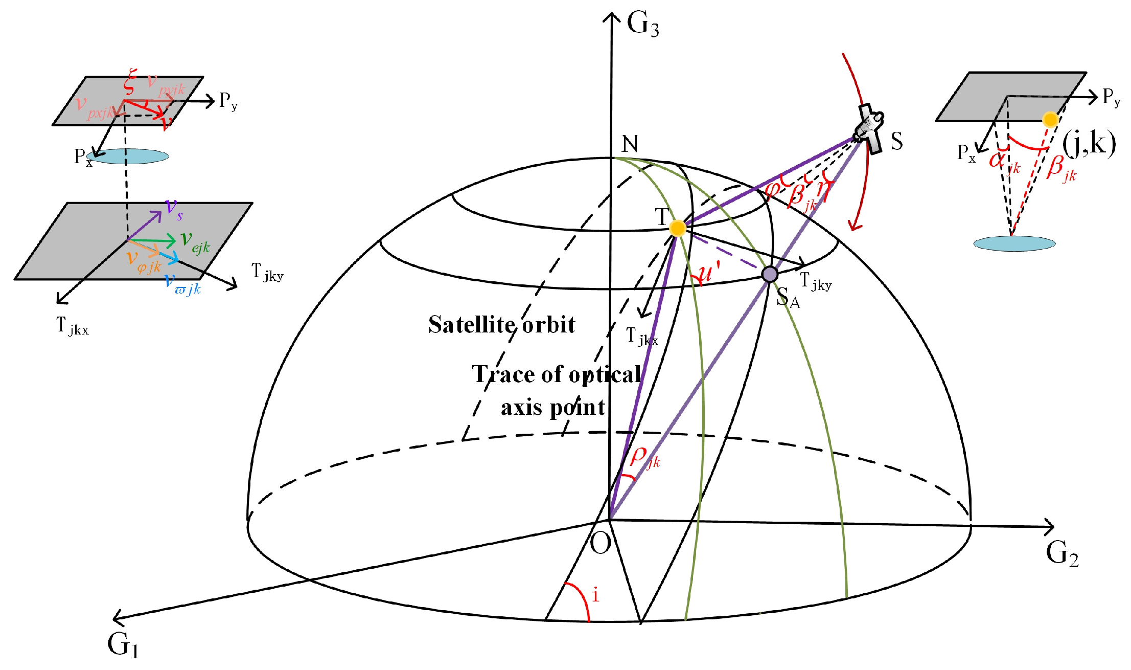
An accurate velocity vector model on the image plane is the key to formulating the velocity vector matching strategy. Firstly, the precise positions of objects are determined through the object-image mapping relationship. Secondly, the velocity vector on the object space is described and decomposed. Finally, the velocity vector on the image plane is obtained by projecting the velocity vector from object to image. As shown in Figure 3 the process involves several right-handed coordinate systems: image coordinate system P ( P x , P y , P z ) and object coordinate systems P j k ( P j k x , P j k y ) . The origin of P ( P x , P y , P z ) is at the center of the image plane. P x axis, on the image plane, points to the direction of the satellite flight. P z axis is parallel to the optical axis and points to the center of the earth. ( j , k ) stands for the serial number of pixels. The row number is j ( M , M ) , and the column number is k ( N , N ) . There are D pixels in total, corresponding to D object coordinate systems. Their origins are at objects. T j k x axis is tangential to the earth’s surface and points to the direction of satellite flight. T j k x axis is perpendicular to the T j k y axis, tangential to the earth’s surface, and pointing in the direction of the earth’s rotation.

3.1.1. The Position of Objects

It is very important to solve the position of object which is conjugated to each pixel because that the linear velocities of the earth’s rotation, satellite attitude and swing mirror change with the positions of objects. Starting from arrangement rule of pixels and combining pixel angle, optical axis angle and geocentric angle, the latitudes of the objects are acquired through coordinate transformation.
Pixel angle is β j k ( t ) shown in Figure 3. The focal length of the satellite is f , and the size of pixel is a . The expression for β j k ( t ) is as follows:
β j k = arctan ( ( sgn ( j ) k sin ( γ j k ) ) a f ) γ j k = arctan ( j / k )
There is symbolic function:
sgn ( j ) = { 1 ,   j > 0 ; 0 ,   j = 0 ; 1 ,   j < 0 ;
Optical axis angle is composed of roll angle φ ( t ) , pixel angle β j k ( t ) and scanning angle of the swing mirror η ( t ) . There are η ( t ) = ϖ t and F O V / 2 η ( t ) F O V / 2 . The equation of ϕ j k ( t ) is:
ϕ j k ( t ) = φ ( t ) + β j k ( t ) + η ( t ) ϕ j k ( t ) arcsin ( R / r )
Geocentric angle ρ j k ( t ) will be acquired by solving Δ O S A T in Figure 3.
ρ j k ( t ) = arcsin [ r sin ( Φ j k ( t ) ) R ] Φ j k ( t )
In the Formulas (14) and (15), R is the radius of the earth. The expression of latitude of nadir point δ s ( t ) can be solved based on Formula (1).
δ s ( t ) = arcsin ( z s ( t ) / ( x s ( t ) ) 2 + ( y s ( t ) ) 2 + ( z s ( t ) ) 2 )
Latitude is the symbol of the position of object. The latitudes of objects δ j k ( t ) , which are affected by satellite attitude and the swing mirror, can be acquired by the spherical triangle Δ N T S A in Figure 3.
δ j k ( t ) = arcsin [ sin ( δ s ( t ) ) cos ( ρ j k ( t ) ) ± cos ( δ s ( t ) ) sin ( ρ j k ( t ) ) cos ( u ( t ) ) ]
There is u ( t ) = arccos ( cos i / cos δ s ) . Under the condition that the satellite is in the prograde orbit ( i < 90 ° ), when the latitude of the optical axis pointing point is higher than the latitude of the nadir point, ‘ + ’ will be taken, otherwise, ‘ ’ will be taken.

3.1.2. Velocity Vector

Based on the latitudes of objects, it is more convenient to first solve the velocity vector on the object space. Four types of velocity vectors can be obtained in each object coordinate system.
1.
The projected linear velocity of the satellite’s flight velocity at the project point: v s j k ( t ) = ω s R cos ( ρ y j k ( t ) ) ;
2.
The linear velocity of the Earth’s rotation at the object point: v e j k ( t ) = ω e R cos ( δ j k ) ;
3.
The linear velocity of roll angle at the object point: v φ j k ( t ) = φ ˙ ( t ) L j k ( t ) cos ( ρ y j k ( t ) + ϕ j k ( t ) ) .
4.
The line velocity of the swing mirror at the object point: v ϖ j k ( t ) = 2 ϖ L j k ( t ) cos ( ρ j k ( t ) + η ( t ) ) .
L j k ( t ) = r 2 + R 2 2 r R cos ( ρ j k ( t ) ) represents the distance from the satellite to object. ω s is the angular velocity of satellite flight. ω e is the angular velocity of the earth’s rotation. Although the velocity vector in the object coordinate system is obtained, it is difficult to directly analyze the image quality change in the object space. Therefore, these velocity vectors are decomposed into the two axes of the object coordinate system, and then they are projected to the image plane for further analysis. v x j k and v y j k represent the velocity components in the direction of axis T x and axis T x , respectively.
v x j k ( t ) = v s j k ( t ) v e j k ( t ) cos ( π u j k ( t ) ) v y j k ( t ) = v φ j k ( t ) + v e j k ( t ) sin ( π u j k ( t ) ) + v ϖ j k ( t )
u j k ( t ) = arccos [ cos ( i ) / cos ( δ j k ( t ) ) ] stands for the angle between v s j k and v e j k . Finally, v s j k and v e j k are projected to the image coordinate system by transformation matrix L T P j k ( t ) to solve the expressions of velocity vectors, v s j k and v e j k , on the image plane.
[ v p x j k ( t ) v p y j k ( t ) ] = L T P j k ( t ) [ v x j k ( t ) v y j k ( t ) ] L T P j k ( t ) = f L j k ( t ) cos ( β j k ( t ) ) B 1 ( Φ j k ( t ) ρ j k ( t ) )
The value of resultant velocity on the image plane is:
V p j k ( t ) = V p x j k 2 ( t ) + V p y j k 2 ( t )

3.2. Velocity Vector Matching

In order to take advantage of the widened width of the swing mirror as much as possible, the initial imaging direction of the detector is along the scanning direction of the swing mirror. However, through the above calculation of the velocity vector, it can be found that the direction of the resultant velocity on the image plane is not consistent with the direction of the initial imaging direction of the detector. It will seriously affect the imaging quality, especially when the image plane is stitched by several detectors. Firstly, the mismatch should be analyzed, and then methods such as adjustment of yaw angle, the tilt of detectors, and adjustment of imaging time of detectors will be taken to match velocity vector.
In the Equation (19), in addition to the velocity v p y j k ( t ) in the initial imaging direction of the detector, there is another velocity v p x j k ( t ) that is perpendicular to the initial imaging direction of the detector. There is an angle between the resultant velocity on the image plane and the initial imaging direction of the detector, which is called the drift angle.
ξ j k ( t ) = arccos ( V p x j k ( t ) / V p j k ( t ) )
ξ j k ( t ) is the mismatching angle of the velocity vector. In addition, the imaging time T i of detectors should be fit with the value of resultant velocity V p j k ( t ) on the image plane. The relationship between V p j k ( t ) and T i is:
T i = a / V p j k ( t )
For the image plane stitched with Q detectors, the position of the center pixel of each detector in the image plane coordinate system is ( q 1 , q 2 ) . The following matching strategies are proposed.
1.
Adjustment of yaw angle: first, during imaging along the coast, the satellite continuously adjusts the yaw angle to ensure that the imaging direction of the detector coincides with the direction of resultant velocity in the center of the image plane. The value of yaw angle is Ψ ( t ) = ξ j = 0 , k = 0 ( t ) ;
2.
Tilt of detectors: adjustment of yaw angle only matches the velocity vector in the center pixel of the image plane. However, the residual mismatched angles of other pixels still exist. These residual mismatched angles can be compensated by tilting the detectors. The tilt angles of detectors are Δ ξ q 1 q 2 ( t ) = ξ q 1 q 2 ( t ) Ψ ( t ) ;
3.
Adjustment of the imaging time of detectors: step 1 and step 2 only consider the direction of the velocity vector. The value of the velocity vector is compensated by adjusting the imaging time of detectors separately.

4. Experiment

The experiment is performed to verify the image quality of matching imaging on agile satellite with wide-swath whisk-broom payloads along the coastal zone. The experimental facilities are one-dimensional turntable, targets, and lens. The image plane of the lens is stitched by three detectors. The turntable drives the camera to rotate to simulate the scanning of the swing mirror. The lens and detectors simulate the camera of satellite. The curvature of target is proportional to Earth’s curvature. The design and results of the experiment are introduced as follows.

4.1. Design of Experiment

In order to obtain the parameters of the experiment, we planned the curve of attitude versus time when the agile satellite with the swing mirror scanning the coastal zone of China. The angular velocity of the swing mirror is calculated. The distribution figure of the drift angle on the image plane is drawn.
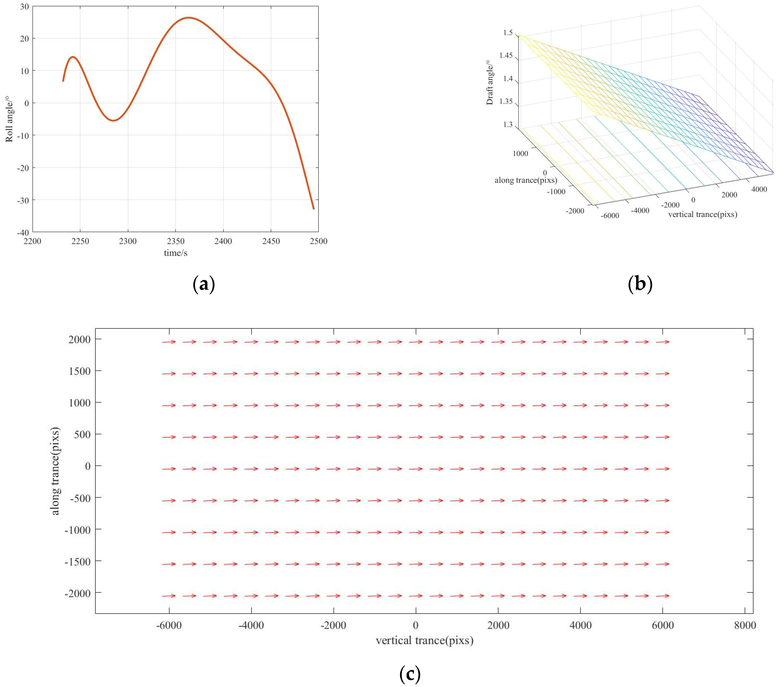
Firstly, the agile satellite with the sun-synchronous orbit is selected to image the southeastern coastal zone of China. The satellite parameters are shown in Table 1. The focal length of satellite is 3.5   m . The size of single pixel of satellite is 7   μ m . Its orbit altitude is 500   km . The ground resolution of the satellite can be calculated as G S D = ( H a ) / f = 1   m . The field of view of the satellite of is 2 ° . The coverage width of satellite can be calculated as W x = 17 . 45   km . According to the satellite orbit parameters and target distribution, the curve of roll angle is demonstrated in Figure 4a. The imaging time region is [ 2242   s , 2485   s ] .
Secondly, the angular velocity of the swing mirror is calculated based on the curve of roll angle. The total length of China’s coastal zone is S = 1 8 , 000   km , with the coverage width of W y = 2 00   km . In the imaging time of 243 s, the angular velocity of the swing mirror can be obtained by Formula (10) as ϖ = 16 ° / s . It ensures that the overlap rate of two adjacent strips is 10.33%.
Finally, the projected linear velocity of the satellite’s flight, the linear velocity of the Earth’s rotation, the linear velocity of roll angle, and the line velocity of the swing mirror are comprehensively analyzed and the velocity vector is calculated by Equation (19). The image plane is spliced by three detectors with size 1024   p i x e l s   ×   1024   p i x e l s . The number of overlapping pixels is 70. Figure 4c shows the distribution of velocity vectors on the image plane at 2367 s. There are drift angles between those velocity vectors and the imaging direction of the detector. Figure 4b shows the value of drift angles. The drift angle at the center pixel ( j = 0 , k = 0 ) is σ = 1.40 ° . The drift angle of the center pixel ( j = ± 1066 ,   k = 0 ) of the side detectors is σ = 1.45 ° .
The experiment simulates the imaging process of the swing mirror at 2367 s. Figure 5 shows the imaging principle and facilities of the experiment. The turntable is equipped with a horizontally placed camera and rotates at angular velocity ϖ = 16 ° / s to simulate scanning process of the swing mirror. The lens and detectors are horizontal and the turntable is tilted at an angle σ = 1.40 ° . The curvature of the spherical surface of target is proportional to the curvature of the earth. The scaling factor is k = H / R . The curvature of the spherical surface of target is r 1 = 28 1   m 1 when the distance between the target and the lens is h = 2.2   m . All parameters in the experiment are shown in Table 2.
When the horizontally placed lens and detectors rotate with the tilt turntable, the velocity vector on the image plane is v ϖ . There is a drift angle σ = 1.40 ° between v ϖ and the imaging direction of the center detector. It simulates the drift angle at the center pixel ( j = 0 , k = 0 ) at time 2367   s . In addition, affected by the curvature of target and the difference in object distances, the drift angle of the side detector is σ = 1.45 ° , showing the asymmetrical distribution of the velocity vector on the image plane at time 2367   s .
The following three corresponding matching strategies are taken:
1.
The lens and detectors are rotated by an angle σ , which is equivalent to adjustment of yaw angle;
2.
The side detectors are tilted by an angle ε = 0.5 ° to compensate for residual mismatched angles;
3.
Adjustment of the imaging time of detectors to compensate for the value of the velocity vector. The imaging time of the center detector is T i 1 = 0.5   ms . The imaging time of the side detector is T i 1 = 0.505   ms .

4.2. Experiment Procedure and Results

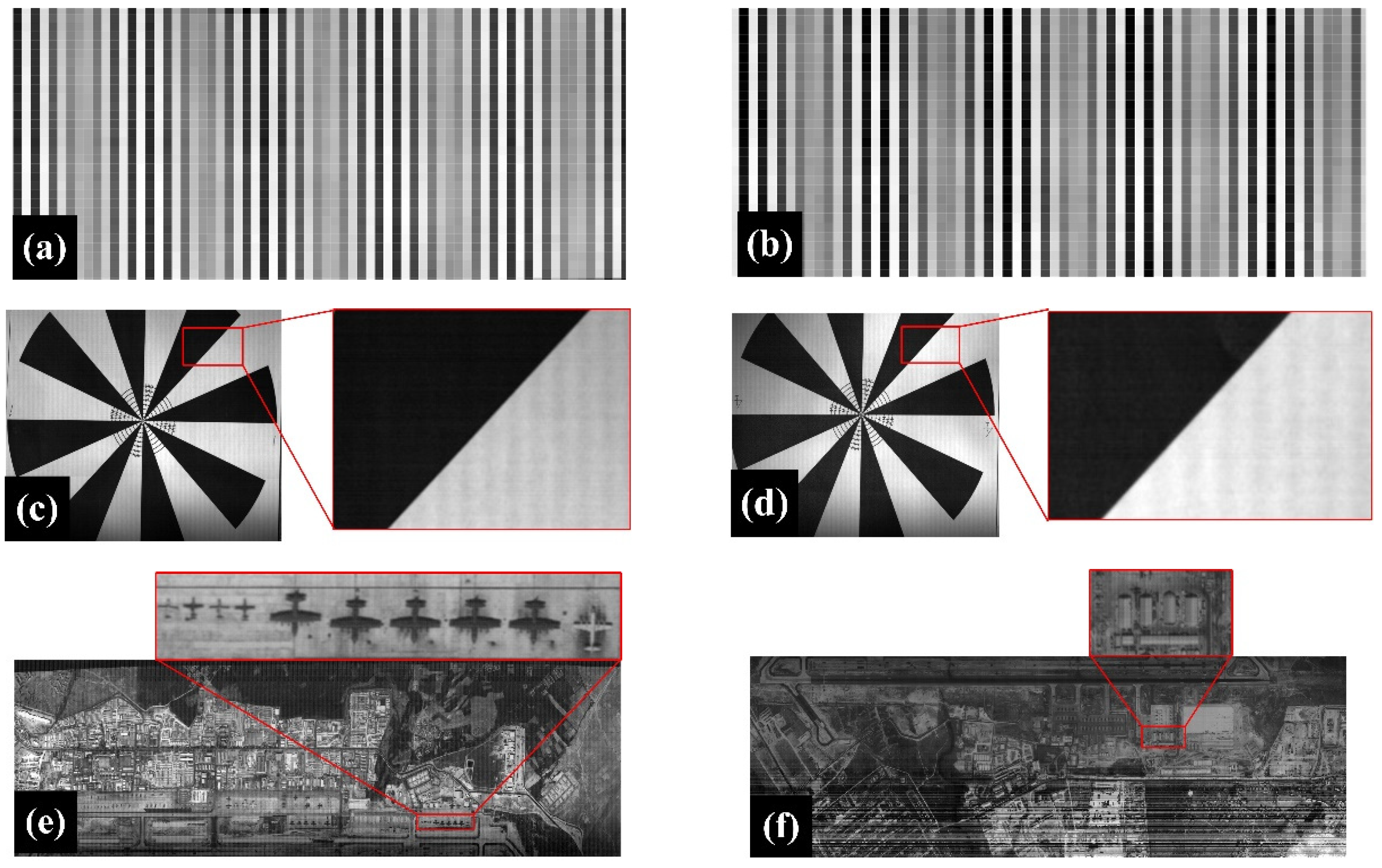
Resolution and modulation transfer function (MTF) are two important indicators for evaluating image quality. The resolution fringes, edge targets, and color targets are imaged through the above experimental methods to verify the feasibility of the matching imaging scheme of agile satellite with the swing mirror. The images acquired from the experiment are shown in Figure 6.

4.2.1. Resolution

As shown in (i) of Figure 5, light-transmitting and opaque strips with a width of A = 0.3   mm are arranged at intervals in resolution target. It is placed in a light-transmitting hole of the camera obscura, which forms bright and dark strip images at intervals. The lens and detectors scans and images the resolution target. The focal length f , the width of strip A , the size of a single pixel a and distance from the lens to target satisfy the resolution imaging relationship A / H = a / f . Figure 6a,b are the images of resolution targets. Each black or white stripe has one pixel width.

4.2.2. Modulation Transfer Function

As shown in (ii) of Figure 5b, the knife-edge target is attached to the spherical surface, which is illuminated by a light. The lens and detectors scan and image the knife-edge target. MTF is calculated by one chosen knife-edge. Figure 6c,d are the images of the knife-edge targe. The chosen knife-edge of detector 1 is M T F 1 = 0.0271 . The chosen knife-edge of detector 2 is M T F 2 = 0.0261 .

4.2.3. Color image

As shown in (iii) of Figure 5b, the color image is attached to the spherical surface, which is also illuminated by a light. The lens and detectors scans and images the color image. Color images respectively taken by detector 1 and detector 2 are shown in Figure 6e,f, which correspond to the upper and lower parts of the target.

5. Discussion

Based on the above three sets of experiments and the experimental images. We discuss whether the image quality meets the imaging needs from three aspects from resolution, MTF, and images of color targets respectively. Firstly, the resolution is analyzed. If our matching scheme is valid, there will be clear strips image in the detectors and each strip occupies one pixel. It can be clearly found that each black or white stripe in the images of detectors has one pixel width. It meets the requirement that resolution is less than 1 pixel; Secondly, MTF is expounded. The image obtained by the optical system is finally observed by the human eye. The minimum MTF of the human eye is M T F e y e = 0.026 . If the MTF of the image is larger than 0.026, it can be considered that the image can be distinguished by the human eye. The MTF of the chosen knife-edge of detector 1 and detector 2 are obtained as M T F 1 = 0.0271 and M T F 2 = 0.0261 , respectively. Both of them are larger than 0.026. It meets the requirement of MTF; Finally, images of color targets are discussed. The two images are taken by detector 1 and detector 2 at the same time. In the image, aircraft mounts and boundaries of house are clear. These indicators show that matching imaging has met the requirements of high quality.

6. Conclusions

The matching imaging method combining attitude adjustment of the agile satellites and the scanning of the swing mirror is proposed to realize full coverage of the coastal zone. Based on the comprehensive consideration of the length, width, and curvature of the coastal zone, an adjustment curve of the roll angle of the agile satellites is planned to ensure scanning along the coastline during the satellite flight. Then, a scanning scheme perpendicular to the coastal zone through the swing mirror is proposed to enlarge the coverage of the wide coastal zone by satellite. The paraments of the swing mirror are calculated to ensure the overlap rate between the adjacent strips is greater than 10%. Finally, the velocity vector model influenced by roll angle and the scanning of the swing mirror is established to calculate the mismatch of velocity vector on the image plane. The adjustment of yaw angle, the tilt of detectors, and the adjustment of the imaging time of detectors are used to eliminate the mismatch and ensure the imaging quality. Experimental results show that the matching imaging method meets the requirement that the resolution is less than 1 pixel. It also meets the requirement that the MTF of our image is larger than the minimum MTF of 0.026 of the human eyes. The matching imaging mode of the satellite attitude adjustment and the scanning of the swing mirror in this paper is suitable for all remote sensing observations of curved and extended targets. The velocity vector matching method can better eliminate the image quality degradation which is caused by the inconsistency between the velocity vector and the imaging direction of the detectors in all dynamic imaging. It has practical value for improving the imaging quality of dynamic remote sensing.

Author Contributions

Conceptualization, J.D. and X.Y.; methodology, J.D. and X.Y.; software, M.W. and J.D.; validation, J.D., X.Y. and Z.F.; formal analysis, J.D. and X.H.; investigation, J.D. and X.H.; resources, X.Y.; data curation, J.D.; writing—original draft preparation, J.D. and X.Y.; writing—review and editing, Z.F. and X.H.; visualization, S.G. and M.W. All authors have read and agreed to the published version of the manuscript.

Funding

This research was funded by the Natural Science Foundation of Jilin Province, grant number 20210101099JC.

Institutional Review Board Statement

Not applicable.

Informed Consent Statement

Not applicable.

Data Availability Statement

Not applicable.

Acknowledgments

The authors would like to thank all of the reviewers for their valuable contributions to our work.

Conflicts of Interest

The authors declare no conflict of interest.

References

  1. Jain, A.; Ramakrishnan, R.; Thomaskutty, A.V.; Agrawal, R.; Rajawat, A.S.; Solanki, H. Topography and morphodynamic study of intertidal mudflats along the eastern coast of the Gulf of Khambhat, India using remote sensing techniques. Remote Sens. Appl.-Soc. Environ. 2022, 27, 100798. [Google Scholar] [CrossRef]
  2. Mao, Y.J.; Harris, D.L.; Xie, Z.Y.; Phinn, S. Global coastal geomorphology-integrating earth observation and geospatial data. Remote Sens. Environ. 2022, 278, 113082. [Google Scholar] [CrossRef]
  3. Amani, M.; Mohseni, F.; Layegh, N.F.; Nazari, M.E.; Fatolazadeh, F.; Salehi, A.; Ahmadi, S.A.; Ebrahimy, H.; Ghorbanian, A.; Jin, S.G.; et al. Remote Sensing Systems for Ocean: A Review (Part 2: Active Systems). IEEE J. Sel. Top. Appl. Earth Obs. Remote Sens. 2022, 15, 1421–1453. [Google Scholar] [CrossRef]
  4. Amani, M.; Ghorbanian, A.; Asgarimehr, M.; Yekkehkhany, B.; Moghimi, A.; Jin, S.G.; Naboureh, A.; Mohseni, F.; Mahdavi, S.; Layegh, N.F. Remote Sensing Systems for Ocean: A Review (Part 1: Passive Systems). IEEE J. Sel. Top. Appl. Earth Obs. Remote Sens. 2022, 15, 210–234. [Google Scholar] [CrossRef]
  5. Benveniste, J.; Mandea, M.; Melet, A.; Ferrier, P. Earth Observations for Coastal Hazards Monitoring and International Services: A European Perspective. Surv. Geophys. 2020, 41, 1185–1208. [Google Scholar] [CrossRef]
  6. Melet, A.; Teatini, P.; Le Cozannet, G.; Jamet, C.; Conversi, A.; Benveniste, J.; Almar, R. Earth Observations for Monitoring Marine Coastal Hazards and Their Drivers. Surv. Geophys. 2020, 41, 1489–1534. [Google Scholar] [CrossRef]
  7. Xu, C.; Yang, X.; Xu, T.; Zhu, L.; Chang, L.; Jin, G.; Qi, X. Study of space optical dynamic push-broom imaging along the trace of targets. Optik 2020, 202, 163640. [Google Scholar] [CrossRef]
  8. Chen, F.S.; Hu, Z.Y.; Li, X.Y.; Yang, L.; Hu, X.J.; Zhang, Y. Research on Wide-Range and High-Resolution Thermal Infrared Remote Sensing Imaging Technology. Chin. J. Lasers-Zhongguo Jiguang 2021, 48, 334–342. [Google Scholar] [CrossRef]
  9. Dolloff, J.; Settergren, R. An Assessment of WorldView-1 Positional Accuracy based on Fifty Contiguous Stereo Pairs of Imagery. Photogramm. Eng. Remote Sens. 2010, 76, 935–943. [Google Scholar] [CrossRef]
  10. Capaldo, P.; Crespi, M.; Fratarcangeli, F.; Nascetti, A.; Pieralice, F. DSM generation from high resolution imagery: Applications with WorldView-1 and Geoeye-1. Ital. J. Remote Sens.-Riv. Ital. Di Telerilevamento 2012, 44, 41–53. [Google Scholar] [CrossRef]
  11. Alkan, M.; Buyuksalih, G.; Sefercik, U.G.; Jacobsen, K. Geometric accuracy and information content of WorldView-1 images. Opt. Eng. 2013, 52, 026201. [Google Scholar] [CrossRef]
  12. Davranche, A.; Lefebvre, G.; Poulin, B. Wetland monitoring using classification trees and SPOT-5 seasonal time series. Remote Sens. Environ. 2010, 114, 552–562. [Google Scholar] [CrossRef] [Green Version]
  13. Candra, D.S.; Sciences, E. Analysis of spot-6 data fusion using gram-schmidt spectral sharpening on rural areas. Int. J. Remote Sens. Earth Sci. 2014, 10, 839–844. [Google Scholar] [CrossRef] [Green Version]
  14. Pu, R.L.; Landry, S.; Yu, Q.Y. Assessing the potential of multi-seasonal high resolution Pleiades satellite imagery for mapping urban tree species. Int. J. Appl. Earth Obs. Geoinf. 2018, 71, 144–158. [Google Scholar] [CrossRef]
  15. Bagnardi, M.; Gonzalez, P.J.; Hooper, A. High-resolution digital elevation model from tri-stereo Pleiades-1 satellite imagery for lava flow volume estimates at Fogo Volcano. Geophys. Res. Lett. 2016, 43, 6267–6275. [Google Scholar] [CrossRef] [Green Version]
  16. Zhi, Z.; Qu, H.; Tao, S.; Zheng, L.; Ying, S.; Zhu, H. The Design of Cone and Pendulum Scanning Mode Using Dual-Camera with Multi-Dimensional Motion Imaging Micro-Nanosatellite. Remote Sens. 2022, 14, 4613. [Google Scholar] [CrossRef]
  17. Lee, L.S.; Lo, K.; Chiang, Y.J. Ocean Color Imager: Instrument description and its performance. Terr. Atmos. Ocean. Sci. 1999, 10, 43–61. [Google Scholar] [CrossRef]
  18. Qiu, W.; Xu, C.; Ren, Z.G.; Teo, K.L. Scheduling and Planning Framework for Time Delay Integration Imaging by Agile Satellite. IEEE Trans. Aerosp. Electron. Syst. 2022, 58, 189–205. [Google Scholar] [CrossRef]
  19. Wahballah, W.A.; Eltohamy, F.; Bazan, T.M. Influence of Attitude Parameters on Image Quality of Very High-Resolution Satellite Telescopes. IEEE Trans. Aerosp. Electron. Syst. 2021, 57, 1177–1183. [Google Scholar] [CrossRef]
  20. Qiu, W.; Xu, C. Attitude Maneuver Planning of Agile Satellites for Time Delay Integration Imaging. J. Guid. Control. Dyn. 2020, 43, 46–59. [Google Scholar] [CrossRef]
  21. Xu, T.; Yang, X.; Wang, S.; Han, J.; Chang, L.; Yue, W. Imaging Velocity Fields Analysis of Space Camera for Dynamic Circular Scanning. IEEE Access 2020, 8, 191574–191585. [Google Scholar] [CrossRef]
  22. Wang, S.E.; Yang, X.B.; Feng, R.P.; Gao, S.N.; Han, J.L. Dynamic Disturbance Analysis of Whiskbroom Area Array Imaging of Aerospace Optical Camera. IEEE Access 2021, 9, 137099–137106. [Google Scholar] [CrossRef]
  23. Prithiviraj, S.; Alyson, L.; Avery, T.; Konstantinos, F. Variable shearing holography with applications to phase imaging and metrology. Light Adv. Manuf. 2022, 3, 193–210. [Google Scholar] [CrossRef]
  24. Han, J.; Yang, X.; Yue, W.; Xu, T.; Wang, S.; Chang, L.; Yang, C. Image Motion of Remote Sensing Camera with Wide Field of View Over the Antarctic and Arctic. IEEE J. Sel. Top. Appl. Earth Obs. Remote Sens. 2021, 14, 3475–3484. [Google Scholar] [CrossRef]
  25. Sun, T.; Long, H.; Liu, B.-C.; Li, Y. Application of side-oblique image-motion blur correction to Kuaizhou-1 agile optical images. Opt. Express 2016, 24, 6665–6679. [Google Scholar] [CrossRef]
  26. Li, W.; Hu, C.; Zhang, L.; Yan, C. Drift angle compensation method for a high-resolution and wide-range space camera. Measurement 2020, 158, 107710. [Google Scholar] [CrossRef]
  27. Guo, Q.; Guan, M. Image rotation modeling for two-dimensional plane mirror scanning and its application in precise image positioning for linear sensor imager on geostationary platform. J. Appl. Remote Sens. 2007, 1, 013524. [Google Scholar] [CrossRef]
  28. Liu, Z.Y.; Gao, L.X.; Wang, J.K.; Tian, Y. Research on the influence of swing mirror of infrared imaging system with image-space scanning. Infrared Phys. Technol. 2018, 92, 459–465. [Google Scholar] [CrossRef]
  29. Stollenwerk, T.; Michaud, V.; Lobe, E.; Picard, M.; Basermann, A.; Botter, T. Agile Earth Observation Satellite Scheduling with a Quantum Annealer. IEEE Trans. Aerosp. Electron. Syst. 2021, 57, 3520–3528. [Google Scholar] [CrossRef]
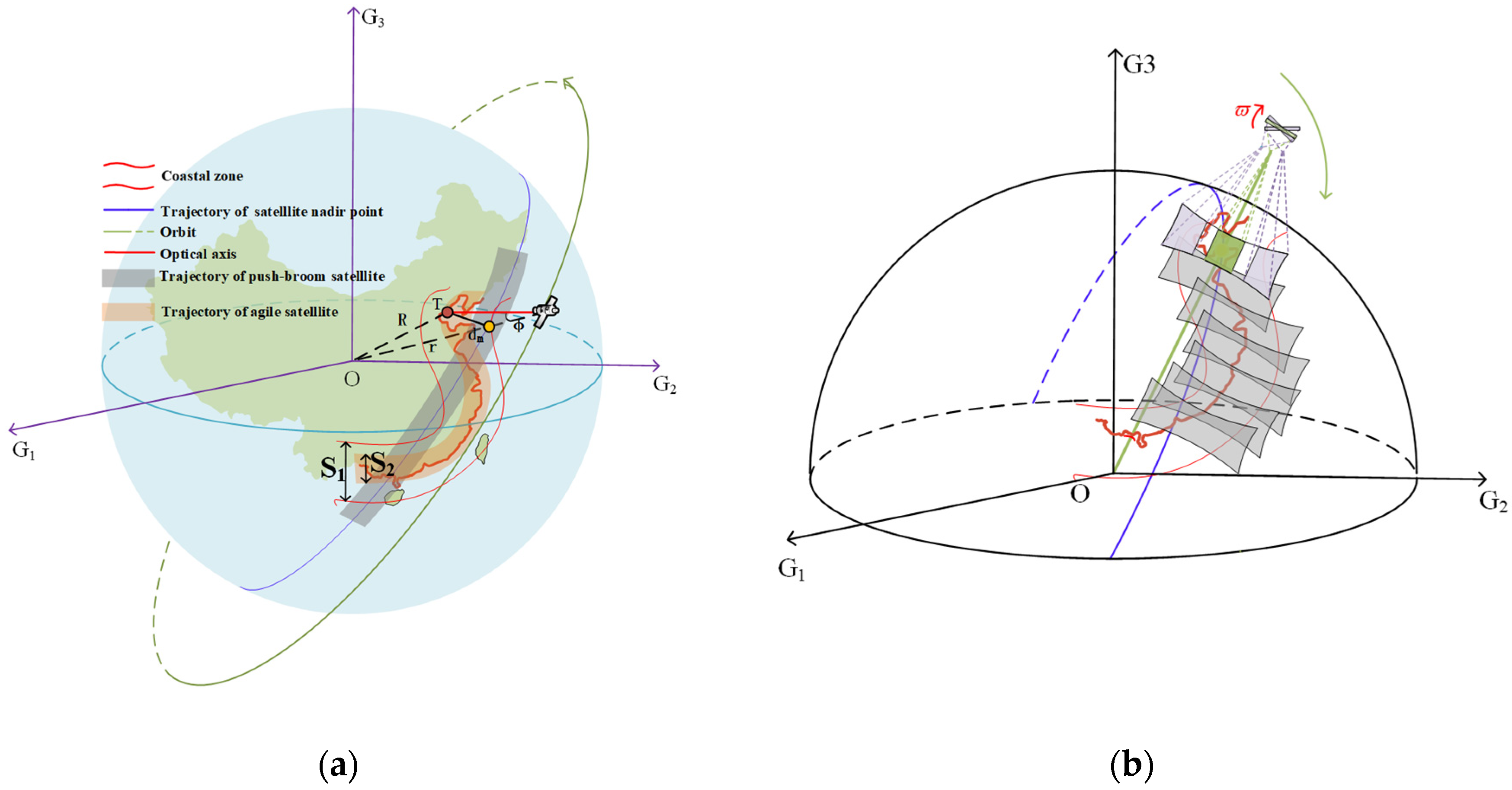
Figure 1. The full coverage technology along the coastal zone: (a) Attitude adjustment of the agile satellite along the coastline; (b) The swing mirror is used to realize full coverage of the coastal zone based on the agile satellite.
Photonics 09 00930 g001
Figure 2. Wide-swath whiskbroom imaging with the swing mirror: (a) Optical system of scanning imaging along the coastal zone; (b) The imaging trajectory of the swing mirror.
Photonics 09 00930 g002
Figure 3. Establishment of velocity vector.
Photonics 09 00930 g003
Figure 4. Roll angel and velocity vector: (a) The curve of roll angle; (b) The value of drift angles at 2367 s; (c) the distribution of velocity vectors on the image plane at 2367 s.
Photonics 09 00930 g004
Figure 5. Experimental principle and facilities: (a) The imaging principle of experiment; (b) The facilities of experiment.
Photonics 09 00930 g005
Figure 6. Experimental results: (a) Resolution image of detector 1; (b) Resolution image of detector 2; (c) Edge image of detector 1; (d) Edge image of detector 2; (e) Color image of detector 1; (f) Color image of detector 2.
Photonics 09 00930 g006
Table 1. Satellite Orbit Parameters.
ParametersMeaningValue
i Orbital inclination97°
r Semi-major axis6878.14 km
e The eccentricity of satellite orbit0
A N Right ascension of ascending node295°
ω The argument of perigee
M 0 The true perigee angle
U C Epoch time12 July 2021 04:00:00
H Orbit altitude 500   km
α e Greenwich sidereal time6.11 rad
f s The focal length of satellite 3.5   m
a s The size of single pixel of satellite 7   μ m
F O V s The field of view of the satellite 2 °
G S D Ground resolution of the satellite 1   m
W x The coverage width of satellite 17 . 45   km
Table 2. The parameters in the experiment.
ParameterMeaningValue
f Focal length of lens200 mm
a The size of single pixel in the experiment 28   μ m
h The distance between target and lens2.2 m
r 1 The curvature of target 28 1   m 1
ϖ Angular velocity of turntable 16 ° / s
σ Detector tilt angle 1.40 °
Publisher’s Note: MDPI stays neutral with regard to jurisdictional claims in published maps and institutional affiliations.