Article

An Unknown Hidden Target Localization Method Based on Data Decoupling in Complex Scattering Media

1
School of Information Science and Engineering, Ningbo University, Ningbo 315000, China
2
Ningbo Institute of Materials Technology and Engineering, Chinese Academy of Sciences, Ningbo 315000, China
3
Aerospace Information Research Institute, Chinese Academy of Sciences, Beijing 100094, China
4
Qilu Aerospace Information Research Institute, Jinan 250100, China
*
Author to whom correspondence should be addressed.
These authors contributed equally to this work.
Photonics 2022, 9(12), 956; https://doi.org/10.3390/photonics9120956
Submission received: 7 November 2022 / Revised: 24 November 2022 / Accepted: 25 November 2022 / Published: 9 December 2022

Abstract

:
Due to the effect of the complex scattering medium, the photons carrying target information will be attenuated when passing through scattering media, and target localization is difficult. The resolution of the target-position information from scattered images is crucial for achieving accurate target localization in environments such as dense fog in military applications. In this paper, a target localization network incorporating an attention mechanism was designed based on the robust feature resolution ability of neural networks and the characteristics of scattering formation. A training dataset with basic elements was constructed to achieve data decoupling, and then realize the position estimation of targets in different domains in complex scattering environments. Experimental validation showed that the target was accurately localized in speckle images with different domain data by the above method. The results will provide ideas for future research on the localization of typical targets in natural scattering environments.

1. Introduction

The scattering phenomenon is primarily due to the modulation of the target photons in a strongly scattering medium. The original target feature information has significant attenuation, and the scattered image obtained by the camera is incomprehensible to the human eye. Accurate and efficient analysis of target information, including location, from target speckle images is important in daily life and security—particularly in military applications [1,2,3,4,5]. For example, in the military, aerial target positions are detected under complex weather conditions, and ground targets are identified and tracked in harsh environments. The target information obtained from speckle images is also valuable for civil applications.
According to the principle of speckle formation, the scattering medium recodes the incident light field that carries the target information. Several recent studies have investigated the acquisition of target information carried by incident light fields under medium scattering interference. For example, in the wavefront shaping technique, the field of view is limited by the optical memory effect, the scattering scene is not fixed, and the incident light field wavefront cannot be effectively recovered and measured [6,7,8,9]. In the transmission matrix measurement technique, the incident and outgoing light fields of a strongly scattering medium can be related to the transmission matrix of the medium. The incident optical field information is combined with the transmission matrix of the measurement medium to obtain the incident optical field carrying the target information [10,11,12]. However, this requires a complex optical experimental system and is computationally intensive. The acquisition of the target information is influenced by the variable properties of the degree of medium scattering. In complex environments, it is difficult to deconvolve target information by estimating the system point spread function (PSF) and by using the convolution relationship between the scatter generated by the target and that generated by the imaging system [13]. As only the amplitude spectral signal of the target is obtained, speckle correlation-based methods can reconstruct the complete shape information of the target using the hybrid input–output and error-reduction phase recovery algorithm proposed by Fienup et al. [14,15,16,17]. However, the restoration effect has high randomness; thus, the reconstruction quality is not guaranteed, and the location of the reconstruction target cannot be determined [18]. On the basis of the autocorrelation principle, Guo et al. investigated the lateral and axial motions of hidden targets, requiring the imaging process to be within the optical memory effect and suitable for the actions of small objects [19]. In 2012, Jakobsen et al. designed a spatial filtering function to perform the localization of a target by analyzing the situation of the target scatter spot as the observation plane changed [20]. In 2015, K. Jo et al. combined the design of a theoretical model of scattering spot motion with sensors to achieve self-motion position estimation [21]. Akhlaghi et al. (2017) analyzed the target statistical characterization of scattergrams to track hidden targets [22].
To better address the limitations of conventional methods, machine learning and deep-learning methods have been investigated for further resolving the target information of scattered images without using complex physical models. In 2018, Hui et al. proposed the use of a support vector regression algorithm to verify the feasibility of using machine learning to achieve target imaging through scattering media [23]. Deep learning-based algorithms were then used for target imaging in a scattered environment. In 2019, Yang et al. attempted to recover handwritten digital images via U-Net structures using optical fiber and glass diffusers [24]. Li et al. suggested that the IDiffNet network is effective for scattering medium imaging [8], and Guo et al. achieved complex target imaging by combining it with the autocorrelation principle [25]. In the aforementioned research on light-scattering imaging, machine learning and deep-learning methods have been integrated into conventional optical imaging systems with reasonable success. However, for deep learning, the model training requires a large number of paired data. Table 1 shows the highly cited public datasets for current mainstream tasks in the imaging domain.
Additionally, the single form of the learning problem affects the generalization of the model, which cannot be fully adapted to real-world situations. It is important to investigate how deep-learning methods can fully extract target information in scattered images. With a limited amount of target information, it is crucial to estimate the target position hidden behind the scattering medium.
To accomplish target-position information acquisition across data domains in strongly scattering media, this study designed a single-stage target localization network based on the robust feature-resolution capability of neural networks by incorporating global attention mechanisms [26,27,28,29,30,31,32,33]. The construction of a basic element dataset combined with the target localization network was then used to achieve data decoupling and extended to locate unknown complex targets hidden in the scattering environment. In contrast to existing deep-learning applications for light-scattering imaging, we utilized loaded elementary elements as target images. The experimental dataset obtained by designing the optical path was used as the training set for the model. The complex targets were used as the test set. Neural network training was performed to decouple the data and extend them to localize targets of complex objects [33,34,35,36,37,38,39,40]. Experimental results indicated that unknown target localization of speckle images was achieved by addressing the limitations of massive datasets, categories, and target shape desensitization. Moreover, training was performed with a small amount of multitarget data to more accurately evaluate the positions of multiple targets.

2. Principle

2.1. Theory

Scattering imaging is determined when the light source angle is constant within a specific field of view [23,24,25]. The scattering imaging system mainly consists of a laser light source, target, scattering medium, and detector [27,28,29,30,31]. As shown in Figure 1, the relationship between the input target image and the corresponding output scatter pattern captured by the sensor can be expressed as
E o u t = K E i n ,
where E o u t represents the received scattered image, K represents the PSF of the scattering medium (in this study, the diffuser) with size W × H , and E i n represents the vectorized input target image.
At the same time, the scattering imaging system acts as an optical information transmission system [31]. The operational process shown in Figure 1 relies on the photons carrying the target information being randomly modulated by the scattering medium to form an irregular distribution. The detector records this unstable distribution. The PSF (point spread function) can describe the relationship between the object surface photon distribution and the image surface photon distribution. The photon distribution can be defined as the probability set of an optical image, which is macroscopically understood as a light-intensity distribution.
For this process, the target is considered to be the object plane of size M × N . In a conventional optical imaging system, a unit block x i , x i + Δ x on the object plane passes through the optical system to the image plane y i , y i + Δ y , where i is the index of the target pixel, that is, the index of the unit block in the object plane. Let the intensity distribution of the object be T x i , and let the total number of photons emitted by the object surface be proportional to i T x i . Then, the probability that a photon is emitted from the unit block Δ x in the neighborhood of point x i is
P x i = T x i Δ x i T x i Δ x
Equation (2) is normalized as follows:
P x i = T x i
Similarly, in the image plane,
P y i = S y i
The conditional probability K y j x i , which is the PSF of the system, was introduced for the scattering imaging system. The entire scattering imaging system is described as
P y j = i K y j x i P x i = i K y j x i T x i
Thus, the photons exiting the light field still contain the target information according to the propagation process of the photons carrying the target information in the medium, i.e., for coherent light, the light intensity captured by the sensor in the image plane is given as follows:
P y j = Re E y j , x i exp i y j , x i d x i 2
where E y j , x i represents the amplitude distribution of the object plane x i in the image plane y j , and y j , x i represents the phase change in the image plane of a point light source located at y j , which depends strongly on the geometry of the object and its position relative to the image plane. Irradiation of the object in the specified wavelength range of the light source produces complex, seemingly random interference images, known as a scattered image. In the scattered image, the phase information is represented by the light and dark distributions of the light intensity. A reasonable neural network model for target localization can be designed by extracting the target-position information from the scattering pattern.

2.2. Data Setup

In optical imaging, each pixel receives a beam of light at a corresponding spatial position and has different pixel values according to light intensity. The final image obtained by the camera is expressed as the sum of images formed by all lights independently, as shown in Figure 2:
The imaging process can be expressed as:
E i n = i = 0 n f x i ,
where x i represents the beam of light emitted from the target object, and f represents the mapping function of light intensity and pixel value. When the scattering medium is encountered in the process of light propagation, the scattering phenomenon occurs in every light beam, and the speckle image is superimposed on the final imaging surface. The imaging process can be expressed as:
E o u t = K E i n = K i = 0 n f x i ,
It is known from the principles of differential geometry that all complex geometric figures can be approximated as an extensive collection of sufficiently small basic geometric images (e.g., squares). The scattering map is based on the modulation of the target information at each pixel point by scattering imaging. Combined with the propagation probability of the target information, an image containing the target position information is finally collected after the scattering medium. Therefore, this study proposes using basic geometric elements as the training set. Feature extraction using convolutional neural networks involves traversing the principle of each pixel point of the image using a convolutional kernel. A suitable target localization network is designed to learn the position mapping relationship between the scattering map and the basic elements to achieve localization of complex targets.

2.3. Model Design

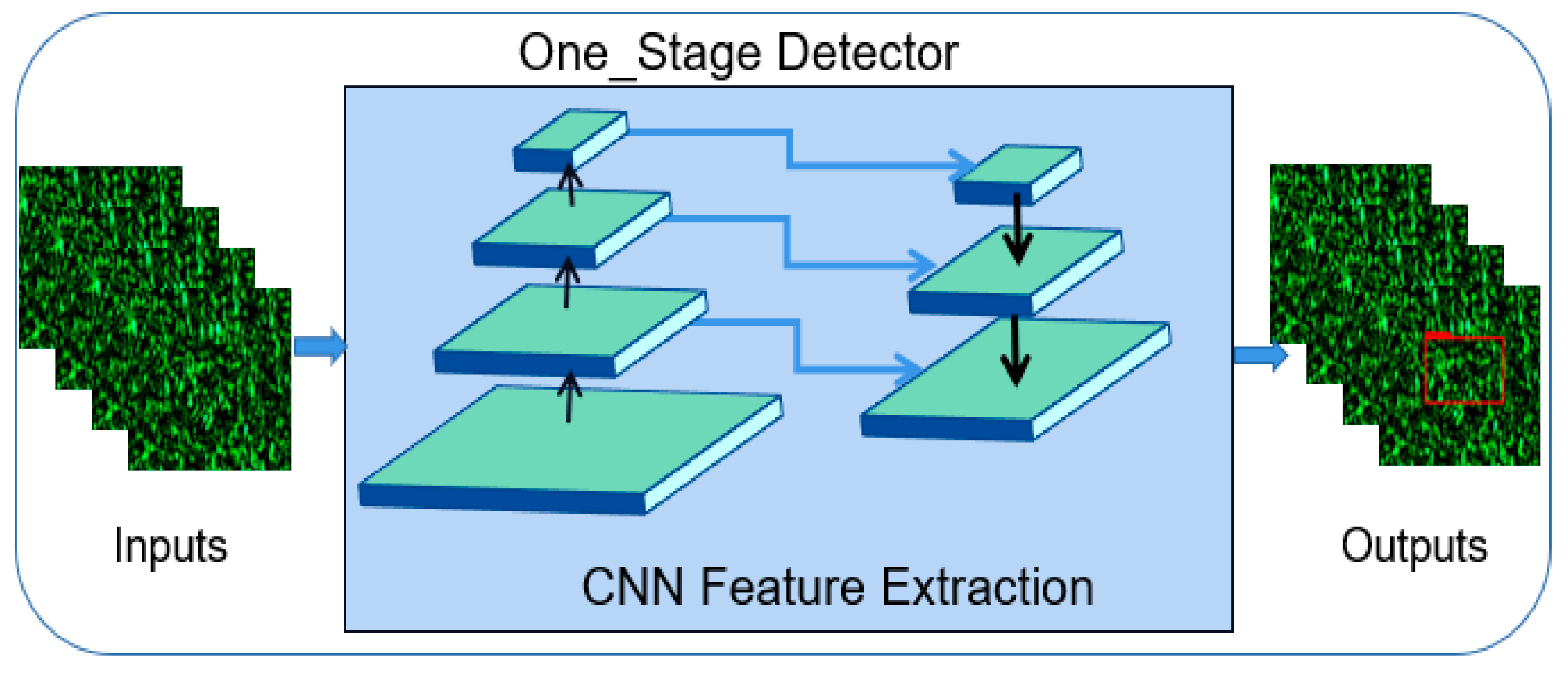
Most target-position detection algorithms are based on convolutional neural networks (CNNs). They mainly include single-stage detection algorithms represented by the YOLO series and multistage detection algorithms represented by the fast R-CNN series. In this experiment, a single-stage target detection algorithm was used. The flow of the algorithm is shown in Figure 3.
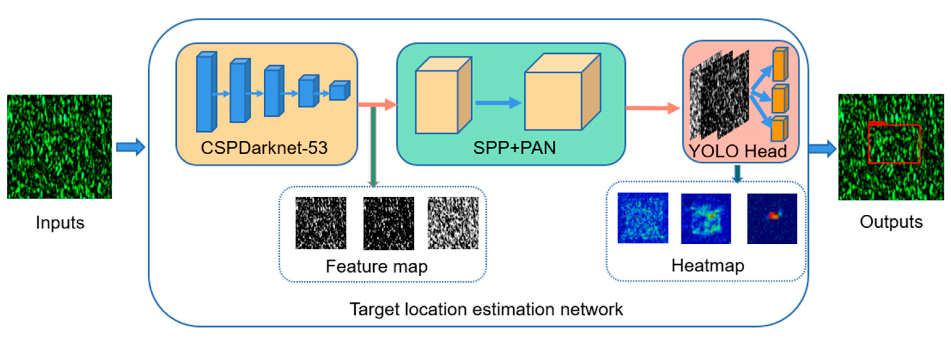
The feature-extraction module of the CNN mainly consists of three parts: feature extraction, fusion, and a detection head that can accurately return the target location. A structural block diagram of the network model is shown in Figure 4.
The feature-extraction module adopts the multichannel CSPDarknet-53 network as its backbone network. The difference between CSPDarknet-53 and Darknet-53 is that the latter contains of a jump-connection layer, which is directly spliced with the feature maps obtained by convolution. It is used to reduce the negative effect of the gradient from pooling and to improve the acquisition of target information. The path aggregation network serves as the feature-fusion module of this network, and the YOLO head serves as the detection head for the regression target location.
In scattering imaging, the image plane is also an optical image with a spatial distribution. According to the target information propagation principle in scattering imaging, the spatial information of the target photon is randomly modulated into the image plane image after being modulated by the scattering medium; that is, the target position and other information are recoded into the scattering image during the propagation process. In this study, target-position information extraction was achieved using a CNN for the resolution of target features.
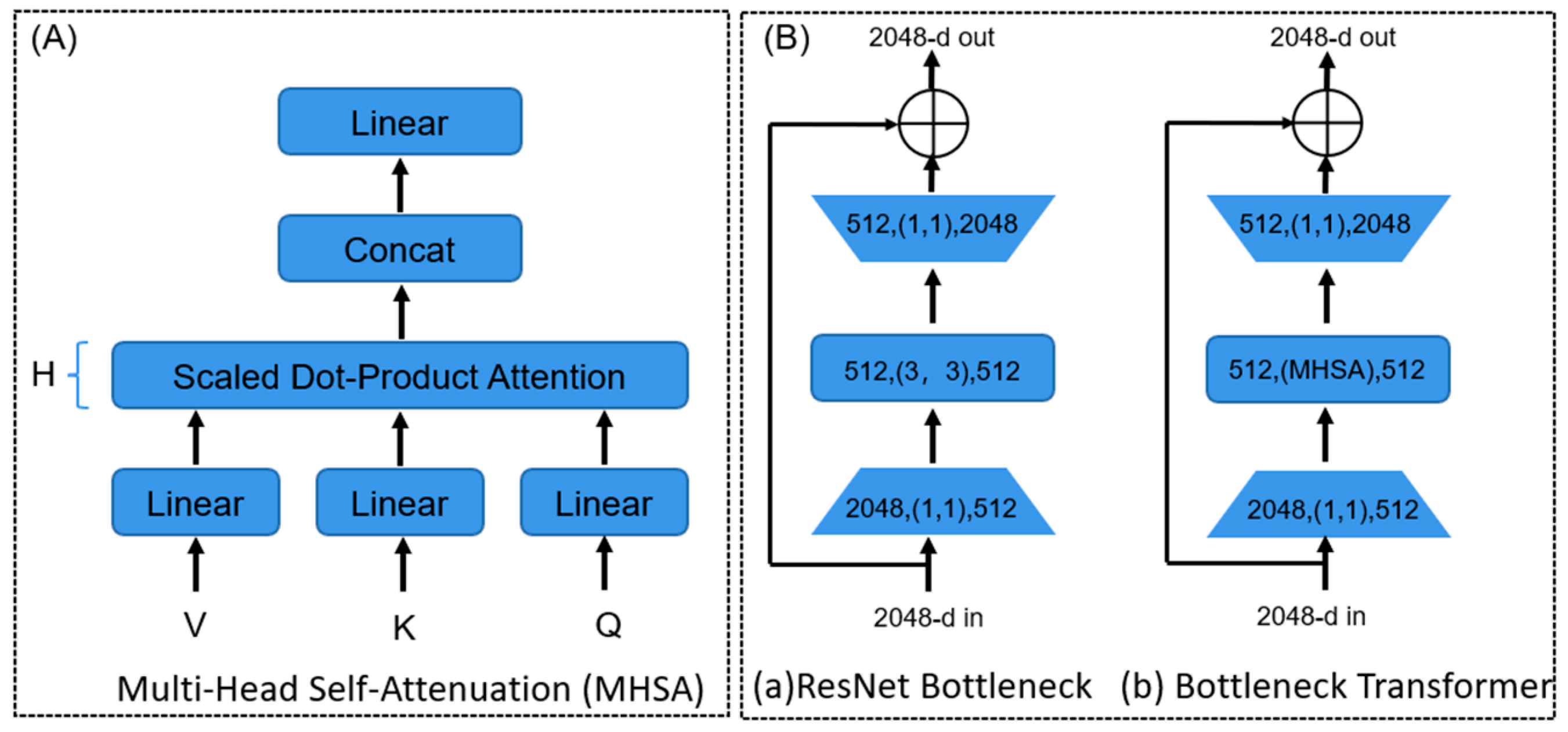
Furthermore, according to the global characteristics of the target information in the scattered image, i.e., the global distribution of the target information photons in the whole scattered image [32]. In contrast, the conventional CNN feature-extraction network cannot fully use global details, owing to its restricted perceptual field. Therefore, a multi-head self-attention (MHSA) layer is introduced in the feature-extraction network (CSPDarknet-53) [39,40]. The global feature relationships are modeled naturally in a hierarchical manner by incrementally computing the global self-attention by increasing the grid and effectively extracting the target associated with the location information in the scattered images. This not only enhances the global feature-resolution capability of the network but also allows the network to better handle multiscale target-position estimation without significantly increasing the computational complexity. Experimental results confirmed that the target localization accuracy of this method could be improved. As shown in Figure 5, the MHSA layer was used to replace the 3 × 3 spatial convolution layers.
The target location detection algorithm used in this study was an end-to-end single-stage target location detection algorithm. According to the network structure and target characteristic analysis, DIOU loss was used as the loss function in the experiment [30]. The loss function was consistent with the actual detection effect of the penalty term. The DIOU loss is expressed as follows:
= 1 D I O U = 1 ( I O U D I O U ) = 1 I O U + ρ 2 b , b g t c 2 ,
where b and b g t represent the centroids of the two rectangular boxes, ρ represents the Euclidean distance between the two rectangular boxes, and c represents the distance between the diagonals of the closed regions of the two rectangular boxes. The optimization objective of the DIOU loss is to minimize the Euclidean distance between the centroids of the two rectangular boxes. c prevents the value of the loss function from being too large and accelerates the convergence. This loss function enhances the accuracy of the network localization for detecting and localizing targets in scattered images. To avoid network overfitting, the weight decay coefficient was set as 0.0001. Stochastic gradient descent was used to optimize the loss function, accelerate the model convergence, and improve the model training.

3. Results and Analysis

3.1. Optical Imaging System

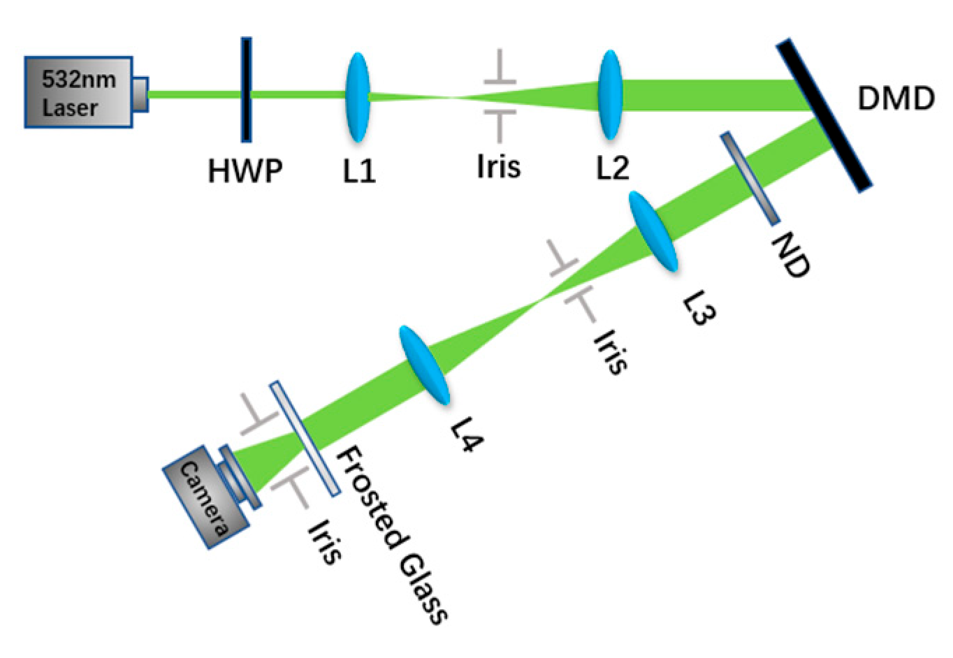
The optical experimental design used for the experimental data acquisition is shown in Figure 6. A half-wave plate (Edmund, HWP, #49-210) modulated a 532-nm green laser. The aim was to combine the spatial light modulator and adjust the polarization state of the incident light to improve the utilization of the incident light by the modulator. Then, the laser light source was used as an illumination light source f L 1 = 35   m m , f L 2 = 40   m m after being expanded and collimated through a lens combination. The incident beam was modulated using a spatial light modulator (DMD digital micromirror array) (resolution of 1024 × 768 and pixel size of 13.7 μm, used to encode and display the virtual target) to obtain the target image. The collimated laser beam carrying the target information was modulated by a f L 3 = 250 mm   ,   f L 4 = 100 m m system and scattered in the incident static scattering medium. The detector received a scattered field image (PYTHON1300 CMOS camera). The distance between the scattering target and the scattering medium was   Z 1 . Frosted glass (gross glass, 220 mesh) was placed between the CMOS and DMD, and the detector was placed behind the scattering medium. The scattering intensity was recorded, during which the distance between the detector target surface and the scattering medium was d = 50 mm.
To obtain speckle images of different targets, basic elements such as circles, triangles, and squares of different sizes, their rotational variations, and random positions as virtual objects were used as initial data for simple targets. Handwritten numbers and combinatorial forms were used as unknown complex targets hidden behind the scatterer. The optical path design of the aforementioned experiments was used to obtain the scattered images of the targets. To verify the feasibility of the method, the scattering data collected from the basic elements were used as the training set for the experiment. The scattering data collected from humans and complex unknown targets were used as the validation set for the experiments. As shown in Figure 7, the basic geometric target entered the DMD, and the obtained scattered images were not recognizable as targets by the human eye.

3.2. Data Preprocessing and Model Training

For the experiments, the collected datasets were normalized. A total of 8000 basic element datasets from preprocessed training datasets and 2000 datasets from complex target collection were used for testing. The 8000 sets of training images were fed into the experimentally designed network, where scattergrams and truth location annotation files were used as inputs to the network. For better model convergence, the batch size was set to 8 using the Adam optimizer with a characteristic learning rate of 10 6 and a total of 100 training epochs in our study. Meanwhile, the input scatter image size is (512,512). The neural network models were run on a computing platform based on the PyTorch deep-learning framework with a central processing unit (i7-8700) and graphics processing unit (RTX2080Ti) as the core, accelerated by PyTorch 1.9 and CUDA10.1.
The loss function curves for the single primitive target training set and its validation set under the gross glass scattering condition as well as the loss function and validation-function curves for the case of training with the complementary addition of 200 sets of targets consisting of two basic elements and three basic elements are shown in Figure 8 (S, D, and T denote a single target, dual target, and triple target, respectively). As the number of iterations increased, the loss function converged at approximately 65 cycles. The loss function of the validation set also plateaued at this time, indicating that the training results were satisfactory.

3.3. Evaluation Indices

After the scattering data were obtained and preprocessed and the model was trained, the proposed target-position estimation network was validated and analyzed. To demonstrate the robustness and accuracy of the model, the center-position offset pixel value and center-position offset angle between the predicted position box and the actual position box were used as evaluation metrics for target-position estimation under different accuracy thresholds, in addition to the evaluation metrics commonly used in target-position detection, such as the F1 score, average precision (AP), and mean average precision (mAP). The F1 score and mAP are given as follows:
p r e c i s i o n = N T P N T P + N F P r e c a l l = 0 1 p r e c i s i o n r e c a l l d R ,
F 1 = 2 r e c a l l · p r e c i s i o n r e c a l l + p r e c i s i o n ,
R m A P = n = 1 N R A P n N ,
where N T P represents the number of correctly classified positive samples, N F P represents the number of incorrectly classified positive samples, Recall represents the predicted recall (R), Precision represents the predicted accuracy (P), Precision(Recall) represents the value of P(R) in the curve, N represents the number of types of target objects, R A P n represents the value of k for the class of target objects, and AP represents the area of the curve based on the target detection P and R. The center-point offset pixel values and center-point field-of-view offset angle are given as follows:
d p i x e l = x 2 x 1 2 + y 2 y 1 2 ,
θ = arctan d p i x e l h 10 4 l ,
where x 1 , y 1 and x 2 , y 2 are the centroid coordinates of the real and predicted position frames, respectively; d p i x e l denotes the centroid offset pixel; h represents the image element size ( 4.8 μm); l represents the distance between the object plane and the camera (50 mm); and θ represents the centroid offset angle.

3.4. Experimental Results and Analysis

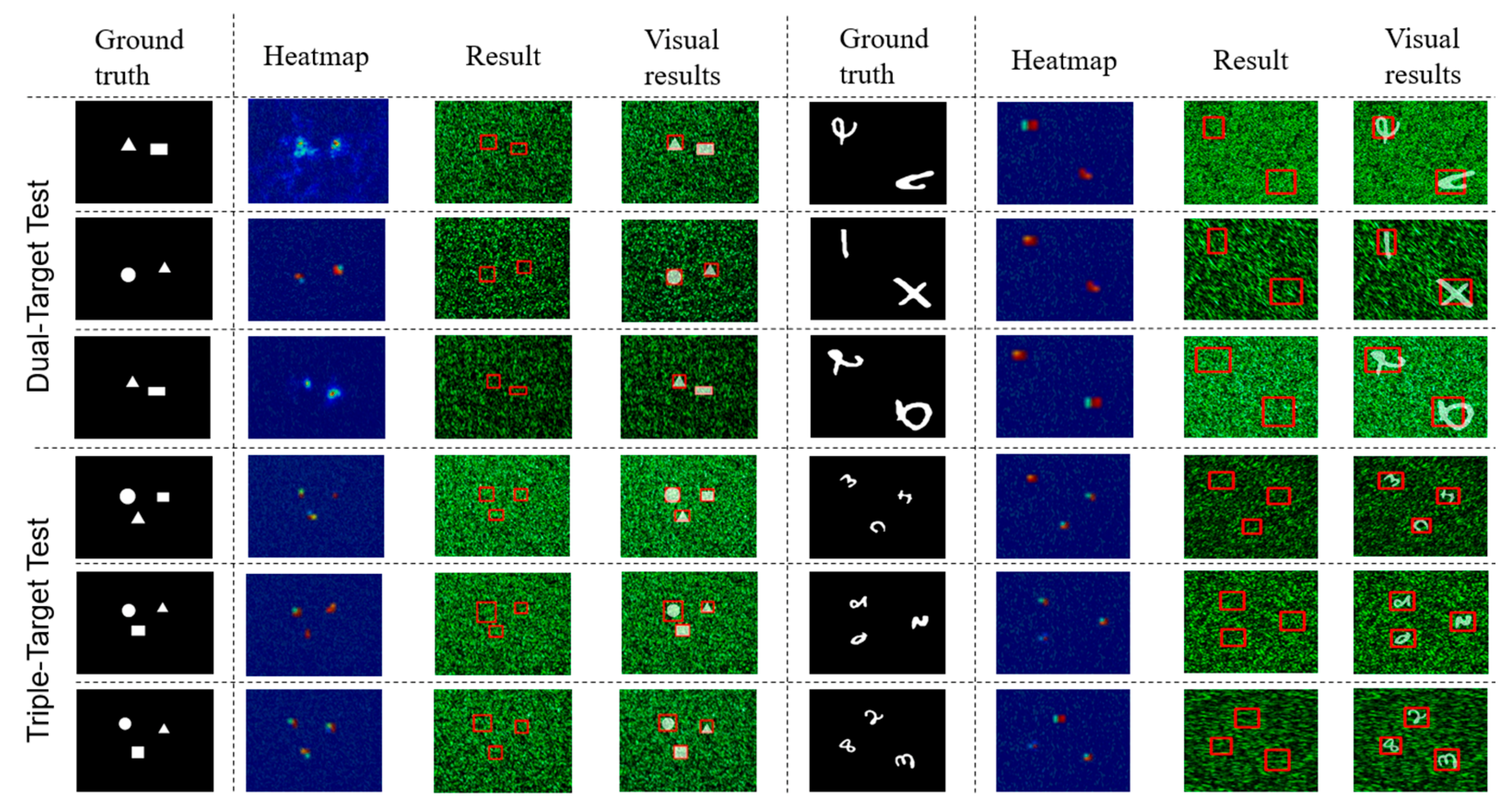
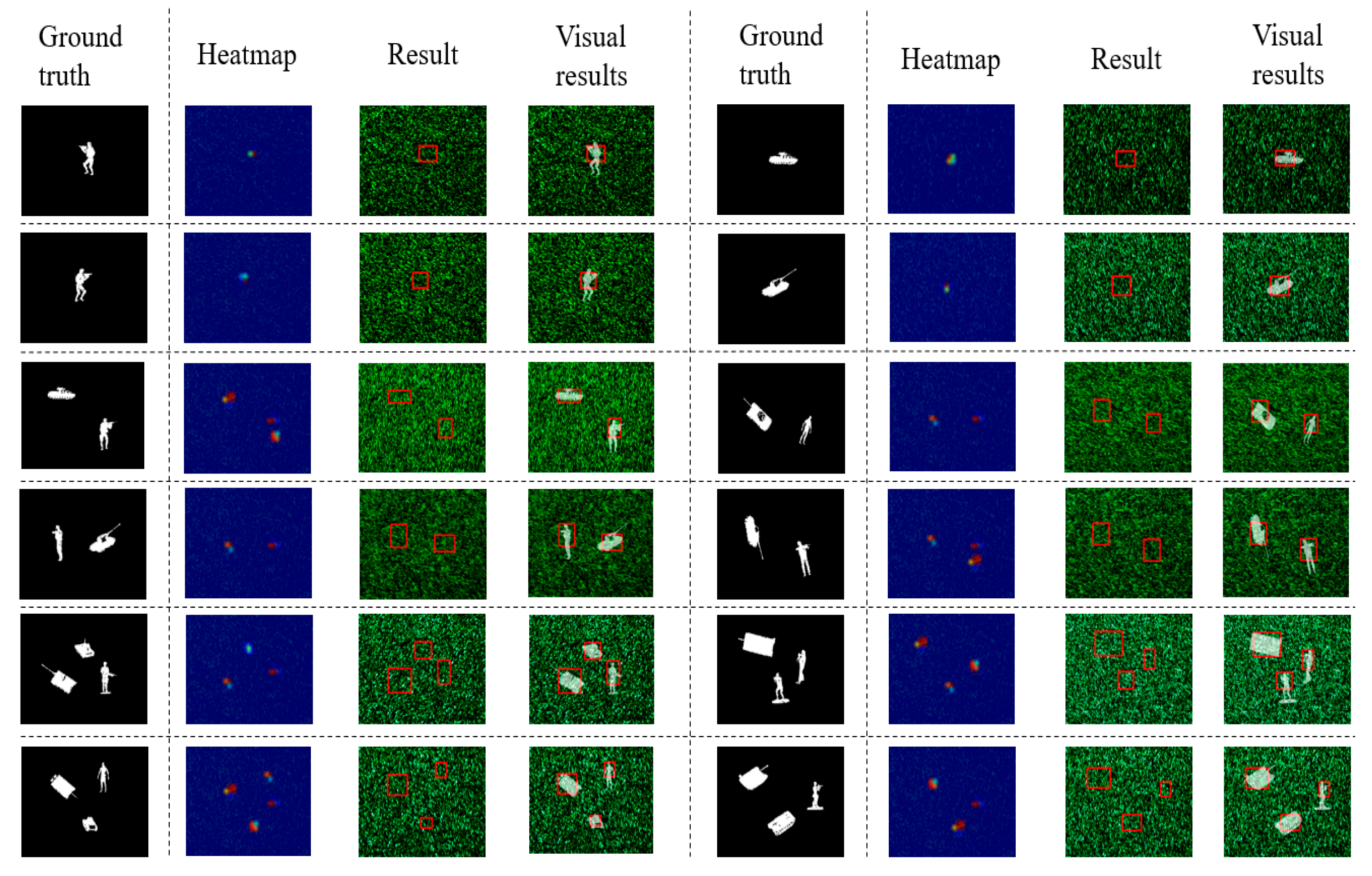
Next, to verify the accuracy of the target localization network, experiments were conducted on a single target dataset consisting of different displacements and their size and shape variations. The test results are shown in Figure 9. Because the scattered images did not characterize the target position significantly, the position was determined using a thermogram. A darker red color corresponded to a larger value in the heat map. It can be considered that the area highlighted in red is the primary basis for judging the accuracy of the target position box. The prediction map was overlaid with an accurate value image to present the results visually.
According to the heatmap analysis, the model can accurately regress the target locations for a single target dataset. To better represent the location estimation accuracy of the model, accurate target locations were overlaid with the predicted results using different transparencies, as shown in the visual results of Figure 9. The results indicated that the model was effective for a single target dataset.
In addition, the accuracy of the model was further validated using a multitarget dataset. The results of this experiment are shown in Figure 10. A total of 200 multitarget datasets consisting of basic elements were selected to be added for model training, and the results were verified using an unknown multitarget test set. The position detection results based on the heatmap indicated that the model accurately regressed the position of each target in the multitarget scattering data. The ideas developed in this study are applicable to target detection in complex multitarget scattered data.
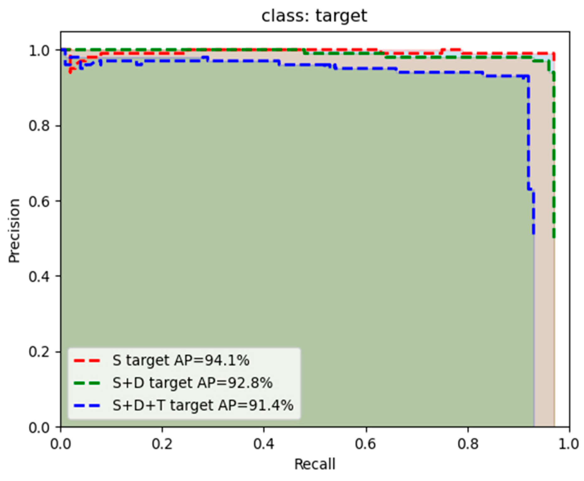
To better evaluate the prediction accuracy of the proposed model, the aforementioned evaluation indices were used. The P–R curves are shown in Figure 11.
When the threshold value was set as 0.5, the average accuracies for the S, S + D, and S + D + T tests were 94.1%, 92.8%, and 91.4%, respectively. The F1 scores and mAP values are presented in Table 2.
As indicated by the data in the table, the accuracy decreased when a small amount of multitarget data was added to the training set, but it was still greater than 90%. This indicates that the model can accurately estimate the locations of targets hidden behind a scattering medium.
To further evaluate the localization accuracy of the model, the number of offset pixels and offset angle between the actual target location and predicted target location centroid were calculated. As shown in Figure 12, the accuracy of the model results varied over specific ranges of offsets and angles. When the number of offset pixels was less than 30 and the angle was 0.25°, the accuracy exceeded 90%.
The results indicated that although the target scattered image cannot be used to clearly identify the target, it contains the target-position information, and the target position in the scattered image can be accurately extracted using the deep-learning method. This validates the proposed approach of localizing complex targets by desensitizing the target shape and limiting the dataset.

3.5. Ablation Experiments

Because the proposed method was improved using YOLO, a comparative study involving ablation experiments was conducted to verify its effectiveness. As shown in Table 3, in the module without the attention mechanism, the target localization accuracy for the existing dataset was 94.1%. In the feature-extraction module, the target localization accuracy was 97.3% when the attention mechanism was added. The number of parameters was increased for the improved algorithm but not significantly. The results indicated a significant increase in the accuracy of target localization in scattered images based on the scattering characteristics due to the global characteristics of the attention mechanism.

3.6. Supplementary Experiments

The objects in this work are black and white, while the grayscale objects are closer to reality. For further verification, the experiment was designed to add a dimmer to the outgoing light field. Because the commonly used steady states of DMD are open and closed, only black-and-white binary images are obtained. The total brightness entering CMOS is reduced by adding a (Neutral Density filter) ND. The experimental optical path is designed as shown in the Figure 13, and then the corresponding speckle image is acquired by simulating the gray-level target image. The same 8000 basic elements datas were collected as the train set and 2000 datas of complex targets as the test set.
The verification results of the collected speckle image dataset are shown in the following Table 4. The performance has decreased, but the idea of the target location of speckle images based on basic elements to achieve complex targets is still feasible.

4. Conclusions

According to the principle of scattershot imaging, the bright and dark spots in the scattershot contain target information. The target location hidden behind the scattering medium can be estimated using valid target information.
This study addressed the limitations of the target data type and shape via neural network feature extraction using basic geometric elements for training. A single-stage target-position estimation network was used for the position estimation of typical unknown targets hidden behind the scattering medium. As shown in Figure 14, the accuracy of the network for detecting the position of a typical target was evaluated.
This network was proven to be widely applicable. It provides new insights and inspiration for the position localization of realistic targets in complex scattering medium conditions and their quantity statistics. In a future study, we will further investigate the effectiveness of the proposed method for target-position estimation in natural environments so that it can be quickly applied to meet practical needs.

Author Contributions

Conceptualization, C.W. and J.Z.; methodology, C.W.; software, C.W.; validation, C.W., S.Y. and Y.Y.; investigation, C.W.; data curation, W.L. and H.Z.; writing—original draft preparation, C.W.; writing—review and editing, S.Y.; supervision, J.X.; project administration, J.X. All authors have read and agreed to the published version of the manuscript.

Funding

This research is supported by the Technology Innovation 2025 Major Project (2020Z019, 2021Z063) of Ningbo and the Natural Science Foundation of Zhejiang (Q23F050006).

Data Availability Statement

Data underlying the results presented in this paper are not publicly available at this time but may be obtained from the authors upon reasonable request.

Acknowledgments

We thank Hanfeng Feng and Zhiyu Wang for technical supports and experimental discussion. We thank the reviewers for useful suggestions.

Conflicts of Interest

The authors declare no conflict of interest.

References

  1. Katz, O.; Heidmann, P.; Fink, M.; Gigan, S. Non-invasive single-shot imaging through scattering layers and around corners via speckle correlations. Nat. Photon. 2014, 8, 784–790. [Google Scholar] [CrossRef] [Green Version]
  2. He, K.; Sun, J.; Tang, X. Single image haze removal using dark channel prior. IEEE Trans. Pattern Anal. Mach. Intell. 2011, 33, 2341–2353. [Google Scholar] [PubMed]
  3. Ntziachristos, V. Going deeper than microscopy: The optical imaging frontier in biology. Nat Methods. 2010, 7, 603–614. [Google Scholar] [CrossRef] [PubMed]
  4. Goodman, J.W. Speckle Phenomena in Optics: Theory and Applications. J. Stat. Phys. 2008, 130, 413–414. [Google Scholar]
  5. Leal-Junior, A.G.; Frizera, A.; Marques, C.; Pontes, M.J. Optical Fiber Specklegram Sensors for Mechanical Measurements: A Review. IEEE Sens. J. 2020, 20, 569–576. [Google Scholar] [CrossRef]
  6. Mosk, A.P.; Lagendijk, A.; Lerosey, G.; Fink, M. Controlling waves in space and time for imaging and focusing in complex media. Nat. Photon. 2012, 6, 283–292. [Google Scholar] [CrossRef] [Green Version]
  7. Vellekoop, I.M.; Mosk, A.P. Focusing coherent light through opaque strongly scattering media. Opt. Lett. 2007, 32, 2309–2311. [Google Scholar] [CrossRef]
  8. Li, S.; Deng, M.; Lee, J.; Sinha, A.; Barbastathis, G. Imaging through glass diffusers using densely connected convolutional networks. Optica 2018, 5, 803–813. [Google Scholar] [CrossRef]
  9. Popoff, S.M.; Lerosey, G.; Carminati, R.; Fink, M.; Boccara, A.C.; Gigan, S. Measuring the transmission matrix in optics: An approach to the study and control of light propagation in disordered media. Phys. Rev. Lett. 2010, 104, 100601. [Google Scholar] [CrossRef]
  10. Meng, R.; Shao, C.; Li, P.; Dong, Y.; Hou, A.; Li, C.; Lin, L.; He, H.; Ma, H. Transmission Mueller matrix imaging with spatial filtering. Opt. Lett. 2021, 46, 4009–4012. [Google Scholar] [CrossRef]
  11. Huang, G.; Wu, D.; Luo, J.; Huang, Y.; Shen, Y. Retrieving the optical transmission matrix of a multimode fiber using the extended Kalman filter. Opt. Express 2020, 28, 9487–9500. [Google Scholar] [CrossRef]
  12. Chen, L.; Singh, R.K.; Chen, Z.; Pu, J. Phase shifting digital holography with the Hanbury Brown-T wiss approach. Opt. Lett. 2020, 45, 212–215. [Google Scholar] [CrossRef]
  13. Chen, L.; Chen, Z.; Singh, R.K.; Pu, J. Imaging of polarimetric-phase object through scattering medium by phase shifting. Opt. Express 2020, 28, 8145–8155. [Google Scholar] [CrossRef]
  14. Bertolotti, J.; Van Putten, E.G.; Blum, C.; Lagendijk, A.; Vos, W.L.; Mosk, A.P. Non-invasive imaging through opaque scattering layers. Nature 2012, 491, 232–234. [Google Scholar] [CrossRef]
  15. Zhu, S.; Guo, E.; Gu, J.; Cui, Q.; Zhou, C.; Bai, L.; Han, J. Efficient color imaging through unknown opaque scattering layers via physics-aware learning. Opt. Express 2021, 29, 40024–40037. [Google Scholar] [CrossRef]
  16. Fienup, J.R. Reconstruction of an object from the modulus of its Fourier transform. Opt. Lett. 1978, 3, 27–29. [Google Scholar] [CrossRef] [Green Version]
  17. Fienup, J.R. Phase retrieval algorithms: A comparison. Appl. Opt. 1982, 21, 2758–2769. [Google Scholar] [CrossRef] [Green Version]
  18. Takajo, H.; Takahashi, T.; Itoh, K.; Fujisaki, T. Reconstruction of an object from its Fourier modulus: Development of the combination algorithm composed of the hybrid input-output algorithm and its converging part. Appl. Opt. 2002, 41, 6143–6153. [Google Scholar] [CrossRef]
  19. Guo, C.; Liu, J.; Wu, T.; Zhu, L.; Shao, X. Tracking moving targets behind a scattering medium via speckle correlation. Appl. Opt. 2018, 57, 905–913. [Google Scholar] [CrossRef]
  20. Jakobsen, M.L.; Yura, H.T.; Hanson, S.G. Spatial filtering velocimetry of objective speckles for measuring out-of-plane motion. Appl. Opt. 2012, 51, 1396–1406. [Google Scholar] [CrossRef] [Green Version]
  21. Jo, K.; Gupta, M.; Nayar, S.K. SpeDo: 6 DOF Ego-Motion Sensor Using Speckle Defocus Imaging. In Proceedings of the IEEE International Conference on Computer Vision (ICCV), Santiago, Chile, 7–13 December 2015; pp. 4319–4327. [Google Scholar] [CrossRef]
  22. Akhlaghi, M.I.; Dogariu, A. Tracking hidden objects using stochastic probing. Optica 2017, 4, 447–453. [Google Scholar] [CrossRef]
  23. Chen, H.; Gao, Y.; Liu, X.; Zhou, Z. Imaging through scattering media using speckle pattern classification based support vector regression. Opt. Express 2018, 26, 26663–26678. [Google Scholar] [CrossRef] [PubMed]
  24. Yang, M.; Liu, Z.H.; Cheng, Z.D.; Xu, J.S.; Li, C.F.; Guo, G.C. Deep hybrid scattering image learning. J. Phys. D Appl. Phys. 2019, 52, 115105. [Google Scholar] [CrossRef] [Green Version]
  25. Guo, E.; Zhu, S.; Sun, Y.; Bai, L.; Zuo, C.; Han, J. Learning-based method to reconstruct complex targets through scattering medium beyond the memory effect. Opt. Express 2020, 28, 2433–2446. [Google Scholar] [CrossRef] [PubMed] [Green Version]
  26. Bochkovskiy, A.; Wang, C.Y.; Liao, H.Y.M. Yolov4: Optimal speed and accuracy of object detection. arXiv 2020, arXiv:2004.10934. Available online: https://arxiv.org/abs/2004.10934 (accessed on 23 April 2020).
  27. Liu, S.; Qi, L.; Qin, H.; Shi, J.; Jia, J. Path Aggregation Network for Instance Segmentation. In Proceedings of the IEEE/CVF Conference on Computer Vision and Pattern Recognition (CVPR), Salt Lake City, UT, USA, 18–23 June 2018; pp. 8759–8768. [Google Scholar] [CrossRef]
  28. Wang, T.; Yuan, L.; Zhang, X.; Feng, J. Distilling Object Detectors with Fine-Grained Feature Imitation. In Proceedings of the IEEE/CVF Conference on Computer Vision and Pattern Recognition (CVPR), Long Beach, CA, USA, 15–20 June 2019; pp. 4928–4937. [Google Scholar] [CrossRef]
  29. Wang, C.; Zhong, C. Adaptive Feature Pyramid Networks for Object Detection. IEEE Access 2021, 9, 107024–107032. [Google Scholar] [CrossRef]
  30. Zheng, Z.; Wang, P.; Liu, W.; Li, J.; Ye, R.; Ren, D. Distance-IoU loss: Faster and better learning for bounding box regression. In Proceedings of the AAAI Conference on Artificial Intelligence, New York, NY, USA, 7–12 February 2020; pp. 12993–13000. [Google Scholar] [CrossRef]
  31. Zhang, X.; Gao, J.; Gan, Y.; Song, C.; Zhang, D.; Zhuang, S.; Han, S.; Lai, P.; Liu, H. Different Channels to Transmit Information in a Scattering Medium. arXiv 2022, arXiv:2207.10270. Available online: https://arxiv.org/abs/2207.10270 (accessed on 21 July 2022).
  32. Sasaki, T.; Leger, J.R. Non-line-of-sight object location estimation from scattered light using plenoptic data. J. Opt. Soc. Am. A 2021, 38, 211–228. [Google Scholar] [CrossRef]
  33. Wang, X.; Jin, X.; Li, J. Blind position detection for large field-of-view scattering imaging. Photon. Res. 2020, 8, 920–928. [Google Scholar] [CrossRef]
  34. Xu, Q.; Sun, B.; Zhao, J.; Wang, Z.; Du, L.; Sun, C.; Li, X.; Li, X. Imaging and Tracking Through Scattering Medium with Low Bit Depth Speckle. IEEE Photonics J. 2020, 12, 1–7. [Google Scholar] [CrossRef]
  35. Lu, Z.; Cao, Y.; Peng, T.; Han, B.; Dong, Q. Tracking objects outside the line of sight using laser Doppler coherent detection. Opt. Express 2022, 30, 31577–31583. [Google Scholar] [CrossRef]
  36. Li, Z.; Liu, B.; Wang, H.; Yi, H.; Chen, Z. Advancement on target ranging and tracking by single-point photon counting lidar. Opt. Express 2022, 30, 29907–29922. [Google Scholar] [CrossRef]
  37. Wang, W.; Zhao, X.; Jiang, Z.; Wen, Y. Deep learning-based scattering removal of light field imaging. Chin. Opt. Lett. 2022, 20, 041101. [Google Scholar] [CrossRef]
  38. Zhan, X.; Gao, J.; Gan, Y.; Song, C.; Zhang, D.; Zhuang, S.; Han, S.; Lai, P.; Liu, H. Roles of scattered and ballistic photons in imaging through scattering media: A deep learning-based study. arXiv 2022, arXiv:2207.10263. Available online: https://arxiv.org/abs/2207.10263 (accessed on 21 July 2022).
  39. Tan, H.; Liu, X.; Yin, B.; Li, X. MHSA-Net: Multihead Self-Attention Network for Occluded Person Re-Identification. IEEE Trans. Neural Netw. Learn. Systems. 2022, 1–15. [Google Scholar] [CrossRef]
  40. Xiao, X.; Zhang, D.; Hu, G.; Jiang, Y.; Xia, S. CNN–MHSA: A Convolutional Neural Network and multi-head self-attention combined approach for detecting phishing websites. Neural Netw. 2020, 125, 303–312. [Google Scholar] [CrossRef]
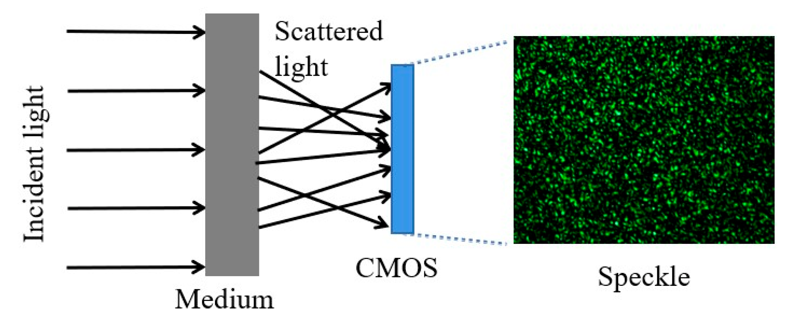
Figure 1. Principle of scatter imaging.
Photonics 09 00956 g001
Figure 2. Complex goal and basic elements relationship.
Photonics 09 00956 g002
Figure 3. Single-stage target-position detection; that is, a single network can perform the target location estimation task. The red box represents the target location results output by the model.
Photonics 09 00956 g003
Figure 4. Efficient position estimation method for unknown hidden targets based on data-decoupled opaque scattering media. The input is the scattered image, and the output is the target-position detection box. In the outputs image, the red box represents the target position result.
Photonics 09 00956 g004
Figure 5. Multi-decoupled feature pyramid network. Information is extracted at different scales and fused to improve the targeting accuracy of the network. (A) is the MHSA network structure, and the principle is to perform self-attentive transformations on Q, K, and V (V is the value vector, Q is the query vector, and K is the key vector) in the MHSA module. In (B), (a) represents the improved backbone, and (b) is the improved backbone.
Photonics 09 00956 g005
Figure 6. (a) Experimental data acquisition optical path diagram; and (b) real experimental environment based on the optical path diagram.
Photonics 09 00956 g006
Figure 7. Example of experimental acquisition data.
Photonics 09 00956 g007
Figure 8. Loss function curves for training and validation.
Photonics 09 00956 g008
Figure 9. Test results for the validation set and a single target dataset of different categories. The “Heatmap” column presents the heatmaps of the output network, where warm colors indicate large values and cool colors indicate small values, i.e., red represents the highest confidence in the regression out of the target position box. The “Result” column presents the output of the network. The “Visual results” column presents results that were used to better characterize the location prediction results. The red box represents the target location results output by the model.
Photonics 09 00956 g009
Figure 10. Results for multitarget testing obtained by adding a small amount of multitarget data for training. The red box represents the target location results output by the model.
Photonics 09 00956 g010
Figure 11. P–R curves and the corresponding AP values.
Photonics 09 00956 g011
Figure 12. Center-point position offset pixels and offset angles in different accuracy ranges.
Photonics 09 00956 g012
Figure 13. Experimental new data acquisition optical path diagram.
Photonics 09 00956 g013
Figure 14. Position estimation results of the proposed method for a typical target. I have checked and revised all.
Photonics 09 00956 g014
Table 1. Comparison of the number of datasets in the deep learning image domain.
Imaging DomainMain Dataset NameQuantity
Object DetectionMS COCO300,000+
Image ClassificationFashion-MNIST70,000+
Image SegmentationPASCAL VOC33,043+
Table 2. Test set accuracy of the model for different numbers of targets.
F1/%AP/%mAP/%
S Target Test92.394.194.1
S + D Target Test91.092.892.8
S + D + T Target Test90.291.491.4
Table 3. Results of the ablation comparison experiment.
Params [M]F1 [%]AP [%]mAP [%]
YOLO V464.3692.394.194.1
MHSA + YOLO V466.1295.297.397.3
Table 4. Scatter test set performance of the model under simulated grayscale targets.
F1/%AP/%mAP/%
S Target Test91.292.692.6
S + D Target Test90.191.391.3
S + D + T Target Test89.890.290.2
Publisher’s Note: MDPI stays neutral with regard to jurisdictional claims in published maps and institutional affiliations.