Article

Piston Error Extraction from Dual-Wavelength Interference Patterns Using Phase Retrieval Technique

1
Key Laboratory on Adaptive Optics, Chinese Academy of Sciences, Chengdu 610209, China
2
School of Optoelectronic Science and Engineering, University of Electronic Science and Technology of China, Chengdu 610054, China
3
Institute of Optics and Electronics, Chinese Academy of Sciences, Chengdu 610209, China
4
University of Chinese Academy of Sciences, Beijing 100049, China
*
Author to whom correspondence should be addressed.
Photonics 2022, 9(2), 111; https://doi.org/10.3390/photonics9020111
Submission received: 4 January 2022 / Revised: 9 February 2022 / Accepted: 11 February 2022 / Published: 16 February 2022

Abstract

:
As next-generation large-aperture telescopes, synthetic aperture is a promising method for realizing high resolution observations. Co-phasing the misaligned segmented aperture is an important procedure for high-resolution observations with segmented telescopes. In this paper, a piston error detection method is proposed based on two interference patterns. Two interference patterns are generated by using a lens placed across two adjacent pupils in the exit pupil plane at two wavelengths and a method based on phase retrieval technique is proposed to extract the piston error from the two interference patterns. The introduction of dual-wavelength in the scheme overcomes the 2π ambiguities problem and expands the piston error detection range. Meanwhile, the proposed piston error extraction method based on phase retrieval technique allows high precision measurement of the piston error and is robust to offset lens. Various simulations are demonstrated and the feasibility of the proposed piston error detection method is validated.

1. Introduction

Astronomical space observations require optical imaging systems with apertures large enough to meet the demands of high resolution. Unfortunately, large aperture optical imaging systems pose huge challenges to manufacturing and costs. The optical synthetic aperture telescope (includes the optical segmented telescope and multi-aperture telescope) is considered to be a mainstream structure for achieving large aperture and high-resolution imagery of new scientific observations [1]. An important work in achieving optimal performance is that the sub-apertures or segments must be phased within a fraction of the wavelength, i.e., correcting for the piston error between apertures and segments [2,3,4].
Currently, there is no single effective method for piston error detection in multi-aperture optical telescopes [3]. Most co-phasing detection uses a combination of multiple technologies. Co-phasing sensors are an important choice for piston error detection. Curvature sensors [5], Zernike phase contrast sensor [6] and the Pyramid sensor [7] are used for the detection of piston errors. A variety of interference-based piston error detection methods is proposed [8,9,10,11]. Dispersed fringe sensor [12,13] and modified Shack–Hartmann sensors are interference-based piston error detection sensors. The modified Shack–Hartmann sensor is successfully applied in the Keck I/II observatory [14,15]. The key element of the modified Shack–Hartmann sensor is an array of prisms or lens placed across two adjacent pupils in the exit pupil plane, which are used to sample the phase information of adjacent sub-apertures and to create a series interference patterns. With a single exposure on a bright star, multiple individual and well-separated interference patterns on the detector are obtained, one for each intersegment edge. The piston error of adjacent sub-apertures can be extracted from measured interference patterns. Many piston error extraction methods based on the measured interference pattern of two adjacent pupils are brought out, such as the peak-ratio method [16] and peak-shift method [17].
Chanan proposes two kinds of piston error extraction methods and refer to them as the narrowband and broadband method, respectively [14,15]. The mathematical model of the KECK telescope is used to establish a series of interference patterns as templates under narrow or broadband light conditions. After that, the correlation coefficients between each interference pattern in the template and the measured interference pattern at narrow band or broadband light from the KECK telescope were calculated. The piston error of the template with the largest correlation coefficient was used as the piston error of the measured interference pattern.
Broadband phasing is used to capture large piston error with low accuracy. Complementing broadband phasing, narrowband phasing improves accuracy at the expense of capture range. In practice, coarse co-phase is generally first performed in broadband phasing, followed by fine co-phase using narrowband phasing [14]. Meanwhile, the above two kinds of methods require that each lens is strictly aligned with the edge of two adjacent pupils; otherwise, the accuracy of these methods will decrease [16,17].
Accordingly, a method called dual-wavelength piston error extraction method (DW-PEEM) is proposed in this paper. The phase retrieval (PR) technique is used to extract piston errors from two interference patterns [18,19], which are generated by lens placed across two adjacent pupils in the exit pupil plane at two wavelengths.
The introduction of dual-wavelength in the scheme overcomes the 2π ambiguities problem and expands the piston error detection range [12,13]. Two interference patterns at two wavelengths can be obtained by repeating the procedure of narrow-band phasing method in two narrow band filters of different and unequally spaced wavelengths. Meanwhile, the proposed piston error extraction method based on PR techniques allows high precision measurement of piston error and is robust to the offset of lens.
In PR techniques, the actual optical system is described by a mathematical model with several different variables [18]. With reference to the above ideas, both the piston error in a synthetic aperture system and the offset of the lens in a modified Hartmann sensor can be used as parameters for the mathematical model. Using the mathematical model of the optical system, multiple reconstructed interference patterns at two wavelengths can be generated. In fact, the mathematical model of the optical system is used to generate a series of interference patterns used as a template in both the narrowband and broadband methods.
A comprehensive metric to evaluate the similarity between the measured and reconstructed interference patterns at two wavelengths is proposed. A series of reconstructed interference patterns was generated by changing the parameters of optical system mathematical model and compared with the measured interference patterns using the piston error and the lens offset as variables in the mathematical model of the optical system and optimization algorithms are used to ensure that the generated reconstructed interference patterns are constantly approaching the measured patterns from the actual system to obtain piston errors.
This paper is organized as follows. In Section 2, the acquisition of the interference patterns at two wavelengths is briefly introduced. Then, the proposed dual-wavelength piston error extraction method in this paper is described in detail. In Section 3, various simulations are used to demonstrate the proposed method. Finally, conclusions and possible future works are provided in Section 4.

2. Theory

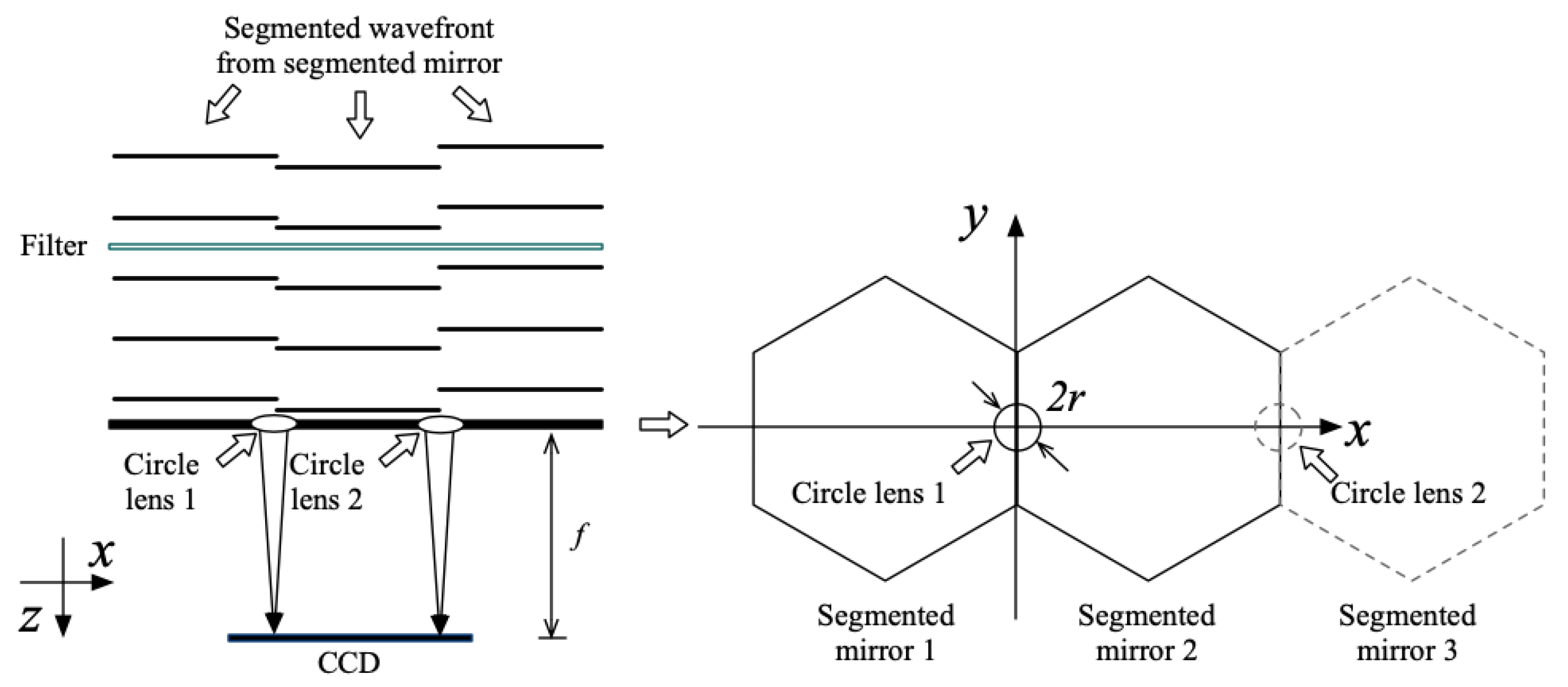
2.1. Interference Patterns Created by the Lens

In this section, the generation of the interference patterns is analyzed theoretically. The analysis is performed for an optical system with three segments, as shown in Figure 1, since the increase in the number of mirror elements introduces no principal changes into the piston error extraction process. The broadband collimated segmented wavefront passes through the filter, and two circle lenses are placed between each segmented wavefront in the exit pupil plane to sample the intersegment edges [14,15,16,17]. By rational design of lens size and focal length, with a single exposure on a bright star, multiple individual and well-separated interference patterns can be generated by the circle lens and captured by the detector [20]. The size of the lens is chosen to be significantly smaller than the atmospheric coherence diameter. This ensures that the results will be insensitive to atmospheric turbulence in all but the poorest conditions [15].
For tutorial purposes and without a loss of generality and taking mirror 1 and mirror 2 as examples and using mirror 1 as a reference, the pupil function with piston error in the pupil exit plane can be written as follows [21]:
E ( x , y ) = circ ( x , y ; r )   ϕ ( x , y ) ϕ ( x , y ) = { 1 x < 0 exp ( j 2 π λ p ) x > 0 ,
where ( x , y ) is the rectangular coordinates in the exit pupil plane, r is the radius of the circle lens, λ is the wavelength and p is the relative piston error between the segmented mirror 2 and the reference segmented mirror (segmented mirror 1).
According to Fourier optics [21], the interference pattern created by the lens can be written as follows:
I ( u , v ) = | F T [ E ( x , y ) ] | 2 ,
where I ( u , v ) is a function of two variables: One is the piston error ( p ) and the other is the wavelength ( λ ). Therefore, I ( u , v ) can be rewritten as I ( p , λ ) . For the convenience of description, these two variables are recorded as a vector V (V = [ p , λ ]).
The piston error extraction method in references [14,16] extracts the piston error from an interference pattern at one specific wavelength. The above methods involve the so-called 2π-problem, which restricts the maximum piston error detection range of the segments to one wavelength. The detection range of the piston error can be extended by introducing additional wavelengths [12,13]. We propose a dual-wavelength piston error detection method. Two interference patterns measured at two wavelengths are used for piston error extraction, which can be expressed as follows.
M I P ( p , λ ) = I ( p , λ )

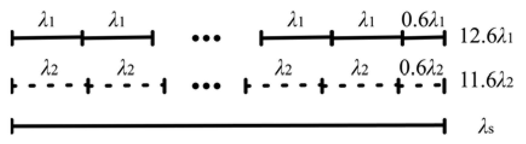
2.2. Extend the Detection Range Using Two Wavelengths

In this section, analysis is performed on how to generate interference patterns at two wavelengths and extend the detection range of piston error. Two interference patterns at two wavelengths can be obtained by repeating the above procedure using two narrow band filters of different and unequally spaced wavelengths.
M I P ( p , λ 1 ) = I ( p , λ 1 ) M I P ( p , λ 2 ) = I ( p , λ 2 )
Note that the detection range of dual-wavelength piston error extraction method is the least common multiple (equivalent wavelength) of wavelength-1 and wavelength-2 [12,13], which is defined as follows.
λ s = λ 1 × λ 2 a b s ( λ 1 λ 2 )
As shown in Figure 2, when wavelength-1 is 580 nm and wavelength-2 is 630 nm; the equivalent wavelength is 7.3 µm.
In the range of 0 to 2 λ s , the interference patterns of different piston errors at dual-wavelengths are calculated and used as the template library in the subsequent analysis. The interference patterns between 0 and λ s are shown in Figure 3.
The single-wavelength method in Ref. [14] evaluated a similarity between the measured interference pattern and the interference pattern in the template library with the correlation coefficient. The correlation coefficient ( C C ) is defined as follows [14]:
C C = i ( x i x ¯ ) ( y i y ¯ ) [ i ( x i x ¯ ) 2 ] 1 2 [ i ( y i y ¯ ) 2 ] 1 2
where x i represents the intensity of the ith pixel in the measured interference pattern, y i represent the intensity of the corresponding pixel in the interference pattern template and represent averages. The sum is taken over by all pixels in the interference patterns.
The metric used for dual-wavelength piston error extraction is redefined as follows:
C C ( λ s ) = C C ( λ 1 ) + C C ( λ 2 ) ,
where C C ( λ 1 ) represents the correlation coefficient of measured interference pattern and interference patterns in template library at wavelength-1, and C C ( λ 2 ) represents the correlation coefficient of measured interference pattern and interference patterns in template library at wavelength-2.
Figure 4 shows the correlation coefficient curve between the measured interference pattern and interference patterns in the template library at two wavelengths (λ1 = 580 nm, λ2 = 630 nm) when the piston error is 4.05 µm. Curves C C ( λ 1 ) and C C ( λ 2 ) are obtained in with the following method: First, two interference pattern template libraries at two wavelengths in the range of 2 λ s are built. After that, when the piston error is 4.05 µm, two measured interference patterns at two wavelengths are obtained separately. Finally, the correlation coefficients between these two measured interference patterns and all interference patterns in corresponding template library are calculated separately. Curve C C ( λ s ) is obtained by summing curves C C ( λ 1 ) and C C ( λ 2 ) .
In Figure 4, curves C C ( λ 1 ) and C C ( λ 2 ) coincide only at 4.05 µm and 11.8 µm. The maxim of the curve C C ( λ s ) is only at 4.05 µm and 11.8 µm. Accordingly, it can be observed that the proposed metric can effectively evaluate piston error within one detection range λs.
The metric (Equation (7)) between the measured interference pattern with Gaussian noise of different SNR and the interference patterns in the template library at two wavelengths (λ1 = 580 nm, λ2 = 630 nm) when the piston error is 3.56 µm are shown in Figure 5. It can be observed that although the metric decreases as SNR decreases, the peak position of the metric still corresponds to 3.56 μm, which means that the metric function can provide the correct piston error under different SNR. The SNR here is defined as S N R = 10 log 10 ( P s i g n a l / P n o i s e ) , P s i g n a l is the power of signal and P n o i s e is the power of gaussian noise.

2.3. Piston Error Extraction Method
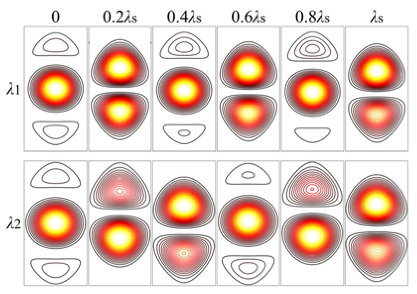
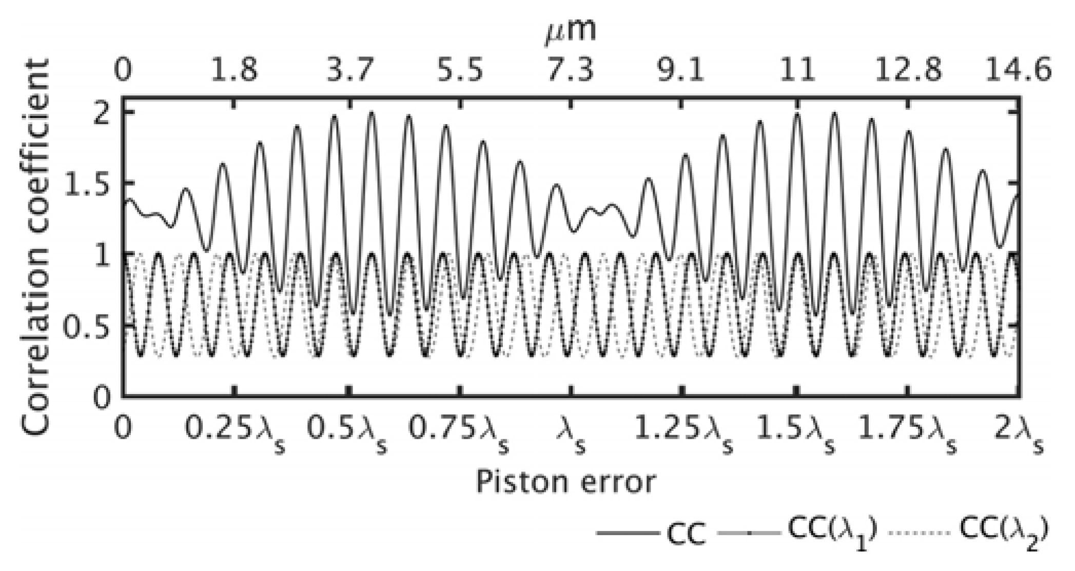
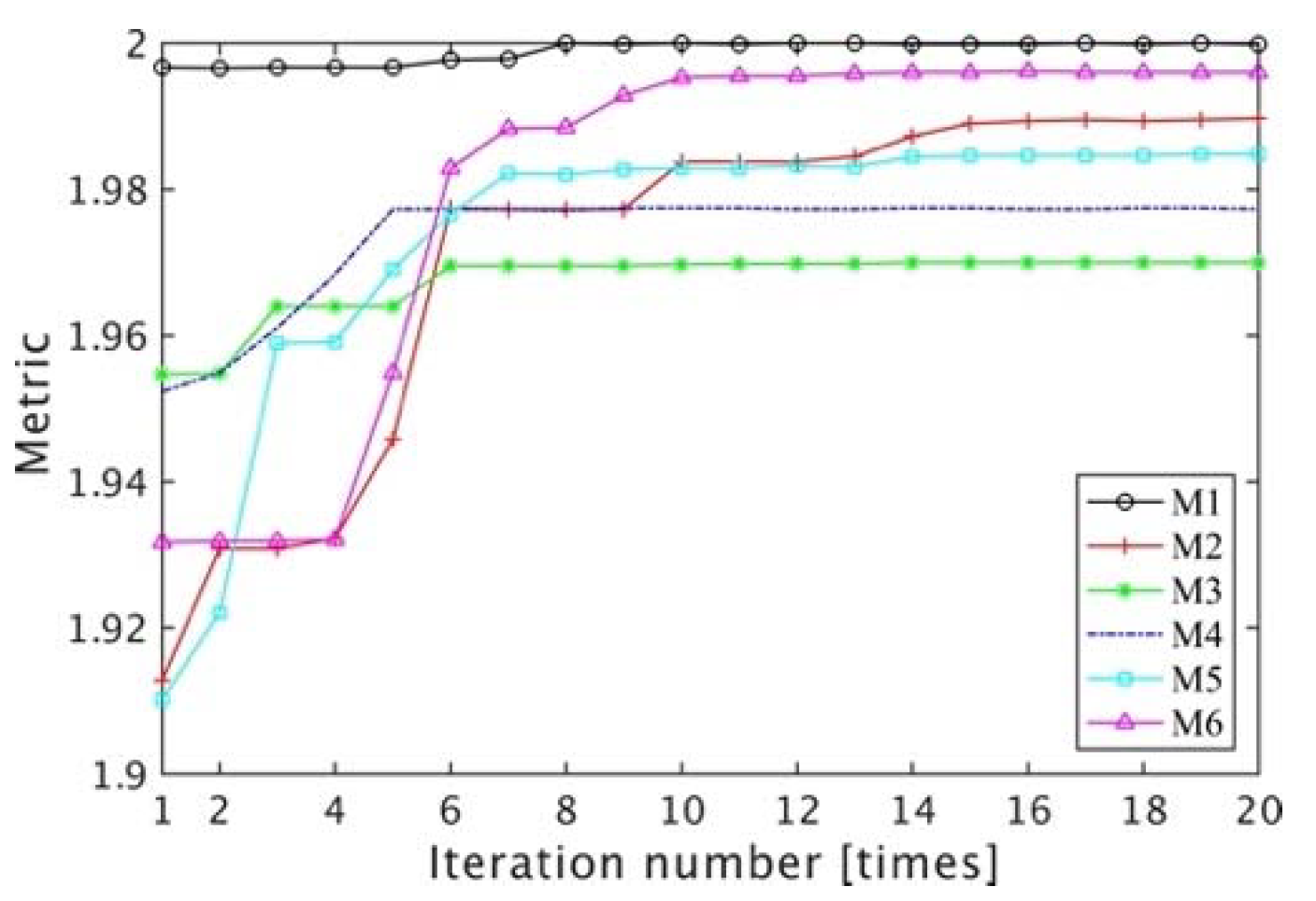
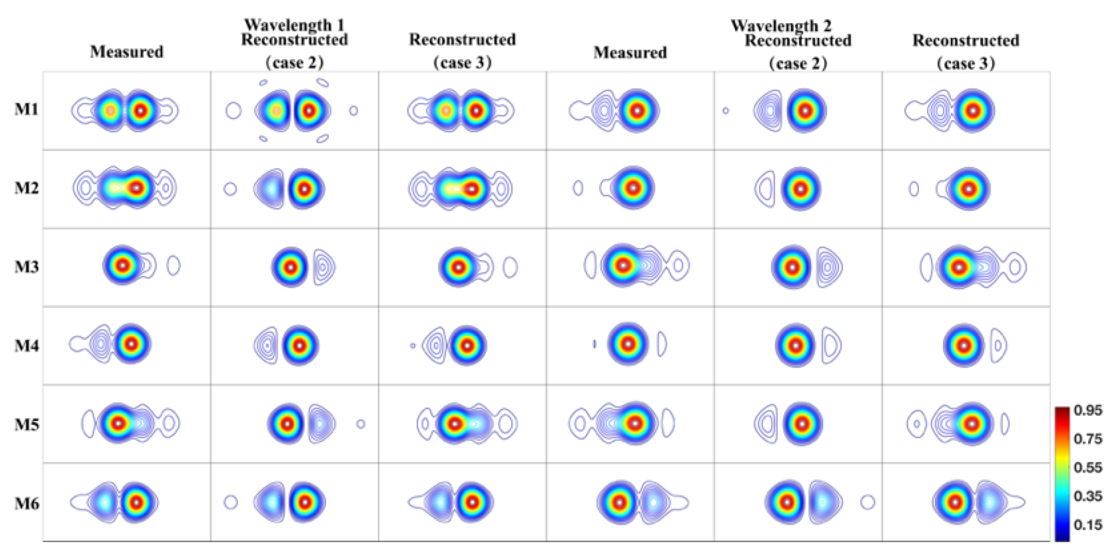
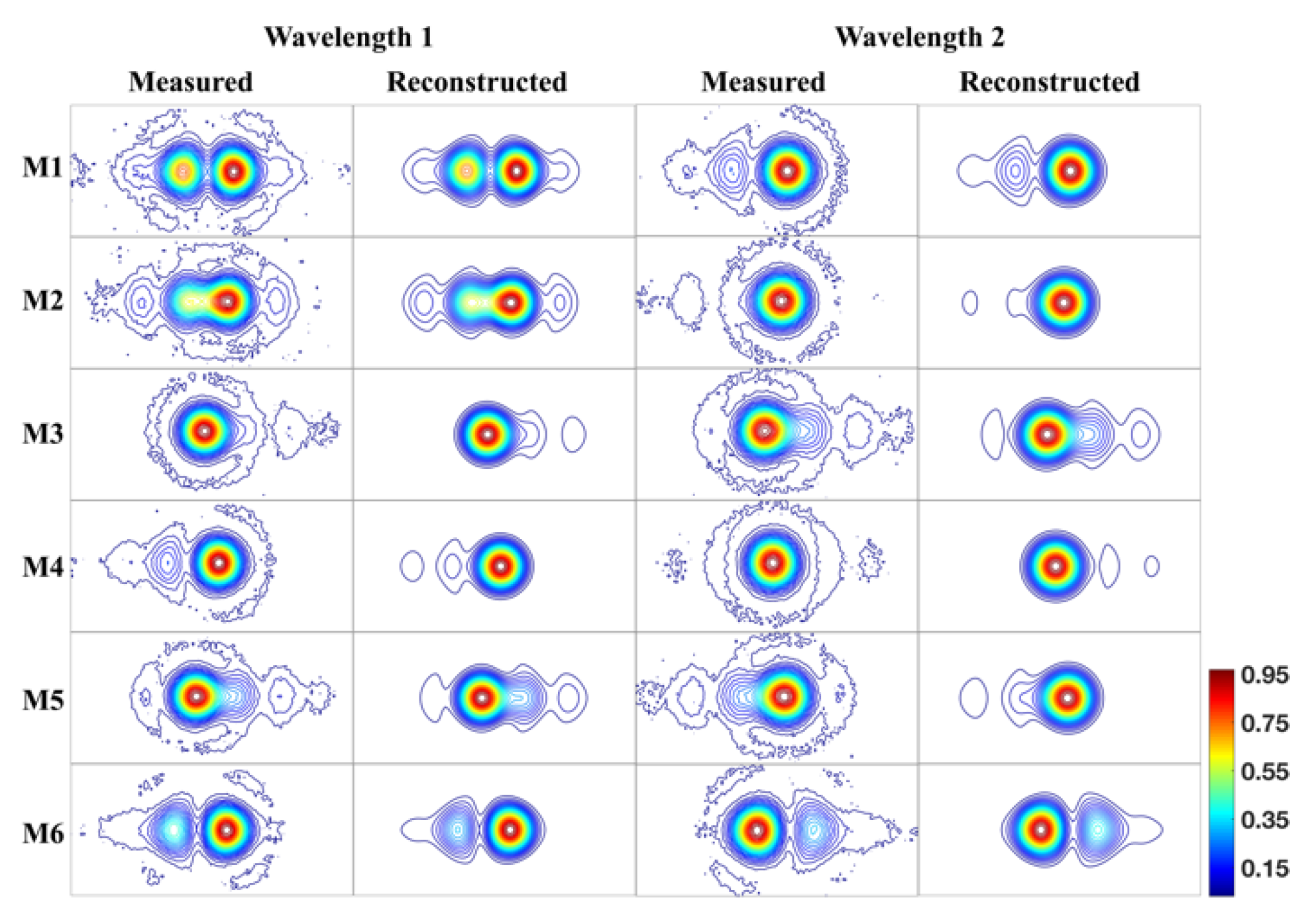
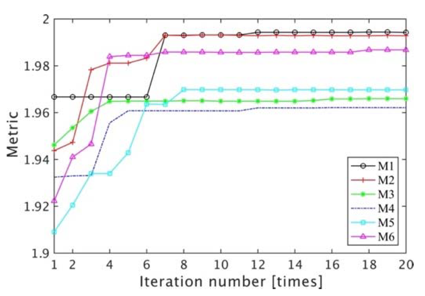
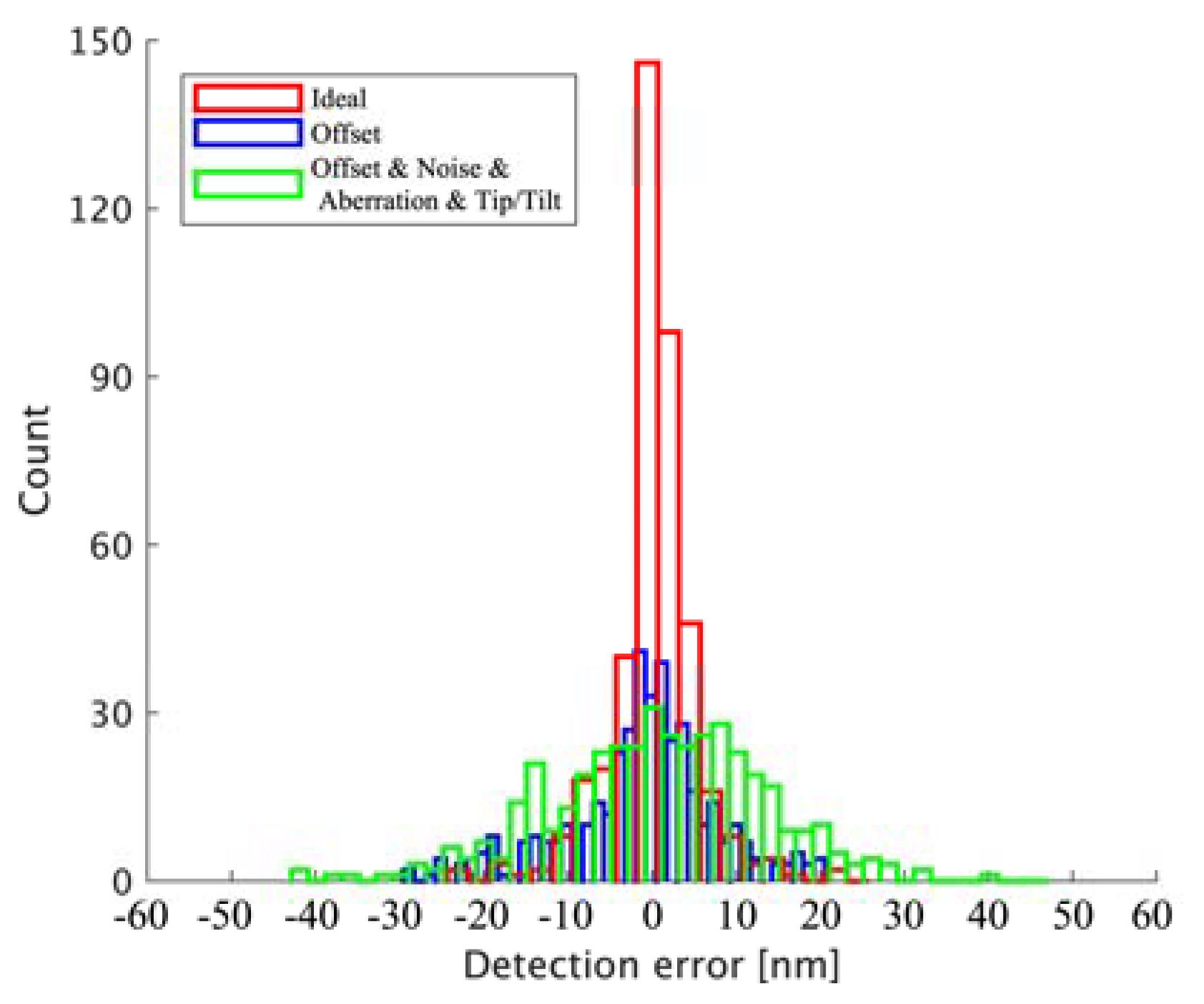
After the above analysis, the method of obtaining two interference patterns using dual-wavelength can extend the range of piston error detection. The simplest method to extract the piston error from two interference patterns is to generate a series of templates with different piston errors at dual-wavelength as two template libraries and calculate their correlation coefficients with the two measured interference patterns and finally calculate metric C C ( λ s ) As shown in Figure 4, the piston error of the templates with the largest C C ( λ s ) is used as the piston error of the measured interference patterns.
However, the above method requires a large number of templates; therefore, a dual-wavelength piston error extraction method (DW-PEEM) based on the phase retrieval (PR) technique [18,19] is proposed in this paper. The advantage of the proposed method is not only the high accuracy of the piston error extraction but also the robustness to the offset of the lens that generates interference patterns.
Based on the PR concept, a series of reconstructed interference patterns was generated at two wavelengths by changing the parameters of the mathematical model of the optical system and an optimization algorithm is introduced to make the reconstructed interference patterns approach to the two measured interference patterns produced by the lens at two wavelengths.
The two reconstructed interference patterns at two wavelengths can be written as follows.
R I P ( p r , λ 1 ) = I ( p r , λ 1 ) R I P ( p r , λ 2 ) = I ( p r , λ 2 )
The metric in Equation (7) can be rewritten as follows.
M ( p r ) = C C [ M I P ( p , λ 1 ) , R I P ( p r , λ 1 ) ] + C C [ M I P ( p , λ 2 ) , R I P ( p r , λ 2 ) ]
The larger the value of M , the greater the similarity between the measured interference patterns and the reconstructed interference patterns. Piston error can be obtained by solving the following optimization problem:
p r * = arg max ( p r ) M ( p r ) ,  
where p r * is the piston error extracted from the interference patterns, and p r Z = [ 0 , 0 , 0 , 0.2418 ] is the optimal variable that needs to be estimated. The optimal variable is recorded as vector V (V = [ p r ]).
The particle swarm optimization algorithm (PSO) [22] with global search capability is chosen to extract piston error. The flowchart of DW-PEEM based on the PSO algorithm is shown in Figure 6.
The PSO algorithm is based on the swarm concept. N particles within the swarm move together in the parameter space, in which each particle can be noted as one vector V. Each particle moves in a certain way to search for a better local maximum and can send information to another and ultimately allow the entire swarm to move toward the same object or in the same direction. The position and velocity of the ith particle in the kth iteration are denoted by V i k and v i k , respectively. At every iteration, these parameters are updated based on the individual and collective knowledge of the swarm. The update formula is given by the following:
v i k + 1 = ω v i k + C 1 r 1 ( V i * V i k ) + C 2 r 2 ( V G V i k ) , V i k + 1 = V i k + v i k + 1 ,
where ω is inertia parameter, C 1 is cognitive parameter, C 2   is social parameter,   r 1   and r 2 are random numbers satisfying 0 r i 1 , i = 1 , 2 , V i * is the position of the point with the best value of the merit function reached so far by the ith particle and V G is the position of the best point reached by the swarm as a whole. It can be observed that, in Equation (11), the change applied to the position of the ith particle depends on the change applied in the previous iteration and the locations of its individual best and the global best.
However, in practice, the offset of lens that is used to create interference patterns will result in the accuracy of piston error detection decrease, as shown in Figure 7.
An improved method to increase robustness to offset lens by adding optimization variables to the optical system model shown in Equation (1) is proposed. The mathematical model of the optical system is rewritten from Equation (1) as follows:
E ( x , y ) = circ ( x + o , y ; r ) ϕ ( x , y ) ϕ ( x , y ) = { 1 x < 0 exp ( j 2 π λ p ) x > 0 ,
where o is the offset value of the lens. The interference pattern is rewritten as a function of three variables I ( o , p , λ ) . One is the piston error ( p ), one is the offset value of the lens ( o ) and the last is the wavelength ( λ ). The metric in Equation (7) can be rewritten as follows.
M ( p r , o r ) = C C [ M I P ( o , p , λ 1 ) , R I P ( o r , p r , λ 1 ) ] + C C [ M I P ( o , p , λ 2 ) , R I P ( o r , p r , λ 2 ) ]
The optimal variable can be rewritten as V = [ o r , p r ] . The optimization problem can be rewritten as follows.
[ o r * , p r * ] = arg   max ( p r , o r ) M ( p r , o r )
The proposed method takes the offset value of lens and piston error of system as optimization variables at the same time to improve the robustness and accuracy of the piston error extraction.

3. Simulation

As shown in Figure 8, we built a platform to create measured interference patterns. The platform is performed for a mirror with seven segments. Taking Sub-0 as the reference, the interference patterns of Sub-0 and the other six pupils have the same pattern and different rotation angles at two wavelengths where there is no piston error between the segments, and the six lenses are in the correct position as shown in Figure 8a. The interference patterns created by lens 1 (M1), lens 2 (M2), lens 3 (M3), lens 4 (M4), lens 5 (M5) and lens 6 (M6) at wavelengths 1 and 2 are noted as M11, M21, M31, M41, M51 and M61 and M12, M22, M32, M42, M52 and M62, respectively. The diameter of the segments in the exit pupil plane is 15 mm. The parameters of the lenses refer to the data in Ref. [15], and the diameter and focus length of the lenses are 2 mm and 120 mm, respectively.
As shown in Figure 8b, four main error sources are considered here to test the proposed method and to improve the realism of the simulation: (1) piston error between segments, (2) higher order aberration in the sub-apertures, (3) offset of lens and (4) Gaussian noise in the interference patterns. The high-order aberration distribution of the incident beam in Figure 8 is generated by summing up Zernike polynomials with random weights from the fourth to eleventh. The unit in Table 1 for the vector of Zernike coefficients is radians. Here, the convention of Noll is used [23]. Zernike coefficients are listed in Table 1. References [24,25] provide reference for the selection of the PSO algorithm. The parameters of PSO algorithm here are optimized. The number of particles between 25 and 40 is the optimum. If the number of particles is too small, there are not enough particles to explore the space adequately and, if it is too large, convergence is slow. When optimal variable V is [ p r ] , the optimal range of ω is between 0.2 and 0.4. When optimal variable V is [ o r , p r ] , the optimal range of ω is between 0.7 and 1. C 1 is usually chosen to be equal to C 2 , and their optimal ranges are between 0.7 and 1.
As shown in Figure 9, the piston error extraction platform with two segments is built, and a series of reconstructed interference patterns can be generated with the left segments as a reference. The PSO algorithm is used to make reconstructed interference patterns generated by the platform, and it continuously approximates measured interference patterns.
It is worth noting that the piston error extraction platform can be directly used to extract the piston error between sub-0 and sub-1 from measurement interference patterns M11 and M12. When used for other measurement interference patterns, the measurement interference patterns need to be rotated, where M21 and M22 need to be rotated counterclockwise by 60 degrees, M31 and M32 need to be rotated counterclockwise by 120 degrees, M41 and M42 need to be rotated counterclockwise by 180 degrees, M51 and M52 need to be rotated counterclockwise by 240 degrees and M61 and M62 need to be rotated counterclockwise by 300 degrees.
In order to evaluate the performance of the proposed DW-PEEM, a series of numerical simulations was carried out in this section, mainly including four cases.
In the first case (case-1), only the piston error is considered, i.e., lenses without offset, which includes sub-pupils without aberration and no noise in the image of interference patterns. Figure 10 shows the measured interference patterns after rotation and corresponding reconstructed interference patterns at two wavelengths, respectively. By comparing measured interference patterns and reconstructed interference patterns, it can be observed that the proposed DW-PEEM works well and the measured interference patterns at two wavelengths are well fitted. Figure 11 shows the metric evolutions of the PSO algorithm used in the piston error extraction method, in which the metric converges to its global minimum value. The result is shown in Table 1. The accuracy of piston error detection is better than 19 nm.
The piston errors are extracted from the interference patterns created by offset lenses in case-2 and case-3. The displacements of the lenses are listed in Table 1.
For comparison, the optimization variable is defined as V = [ p r ] in case-2, but in case-3, the optimization variable is defined as V = [ o r , p r ] . The result is shown in Figure 12 and Table 1. Compared with case-2, the reconstructed interference patterns in case-3 achieves a better approximation relative to the measured interference patterns.
Figure 13 shows the metric evolutions of the DW-PEEM algorithm in case-2 and case-3.
In case-4, the effect of all error sources (noise, offset lens and higher order aberration in sub-pupils) on the performance of the DW-PEEM is shown. The result is shown in Table 1 and Figure 14. The accuracy of piston error detection is better than 32 nm. The metric evolutions of the DW-PEEM algorithm in case-4 are shown in Figure 15.
For accuracy analysis, interference patterns with Gaussian noise for given SNR and Photon noise for given root mean-square value of photons per pixel are digitally simulated. Two hundred separate simulations are performed at different noise levels and different photonics number levels. In each simulation, piston errors between 0 and λ s (equivalent wavelength) and offset between 0 and r/2 (half the radius of the circle lens) are considered. The simulation results for the DW-PEEM in the presence of gaussian noise and photon noise are presented with box plots and shown in Figure 16. On each box, the central mark indicates the median, and the bottom and top edges of the box indicate the 25th and 75th percentiles, respectively. The standard deviations of results are also shown in Figure 16. The whiskers extend to the most extreme data points. The detection error of DW-PEEM is consistently within 24 nm at different SNRs. The detection error of DW-PEEM is consistently within 25 nm at different root mean-square value of photons per pixel. The following results can be derived from Figure 16, where DW-PEEM is robust to Gaussian noise and photon noise.
In order to further illustrate the performance of DW-PEEM, multiple groups of stochastic experiments were conducted under three situations: (1) ideal situation; (2) offset lens situation; (3) offset lens, noise (Gaussian noise and photon noise) and sub-pupil aberrations (including tip/tilt). In addition to Gaussian noise with SNR values of 0.1 dB to 20 dB and sub-pupil aberrations generated by fourth to eleventh order Zernike coefficients between 0 and 1 radians, Poisson noise with root mean-square value 1 to 29 photons per pixel and residual tip/tilt phase error after adaptive optical correction in each sub-pupils generated by second and third order Zernike coefficients between 0 and 0.1 radians were also introduced into stochastic experiments to further improve the realism of simulations. In each situation, 420 stochastic experiments were performed. The statistical experiment results under different situations are shown in Figure 17. The proposed DW-PEEM has good performance and the accuracy of piston error detection is better than 50 nm in all three situations.

4. Conclusions

In conclusion, a piston error extraction method based on PR technique from dual-wavelength interference patterns has been proposed and demonstrated. A series of reconstructed interference patterns was generated using the mathematical model of the optical system at dual-wavelength, their similarity to the measured interference patterns is calculated to obtain a metric and the PSO algorithm is used to extract the piston error by iteratively searching for the maximum value of the metric. The simulation with seven apertures was conducted to prove the effectiveness of the proposed method. It is shown from the results that the method we proposed can not only work with large capture range and high accuracy but is also robust to offset lens used to create interference patterns. Thus, we provide a potential method for measuring piston errors in future optical synthetic aperture telescope.

Author Contributions

Conceptualization, X.L. and X.Y.; methodology, X.L.; software, X.L. and X.Y.; validation, X.L.; formal analysis, X.L.; investigation, X.L.; resources, S.W. and H.X.; data curation, X.L.; writing—original draft preparation, X.L.; writing—review and editing, X.L., X.Y., S.W., B.L. and H.X.; visualization, X.L. All authors have read and agreed to the published version of the manuscript.

Funding

This research was funded by the National Natural Science Foundation of China (NSFC), grant number 11873008.

Institutional Review Board Statement

Not applicable.

Conflicts of Interest

The authors declare no conflict of interest.

References

  1. Fender, S. Synthetic apertures: An overview. In Proceedings of the 27th Annual Technical Symposium, San Diego, CA, USA, 23–25 August 1983; Volume 440, pp. 2–7. [Google Scholar]
  2. Gunturk, B.K.; Miller, N.J.; Watson, E.A. Camera phasing in multi-aperture coherent imaging. Opt. Express 2012, 20, 11796–11805. [Google Scholar] [CrossRef] [PubMed] [Green Version]
  3. Janin-Potiron, P.; Martinez, P.; Baudoz, P.; Carbillet, M. The self-coherent camera as a focal plane phasing sensor. EAS Publ. Ser. 2016, 78–79, 287–305. [Google Scholar] [CrossRef]
  4. Galicher, R.; Baudoz, P.; Rousset, G. Wavefront error correction and Earth-like planet detection by a self-coherent camera in space. Astron. Astrophys. 2008, 488, L9–L12. [Google Scholar] [CrossRef] [Green Version]
  5. Chanan, G.; Troy, M.; Sirko, E. Phase discontinuity sensing: A method for phasing segmented mirrors in the infrared. Appl. Opt. 1999, 38, 704–713. [Google Scholar] [CrossRef] [PubMed]
  6. Surdej, I.; Yaitskova, N.; Gonte, F. On-sky performance of the Zernike phase contrast sensor for the phasing of segmented telescopes. Appl. Opt. 2010, 49, 4052–4062. [Google Scholar] [CrossRef] [PubMed]
  7. Esposito, S.; Pinna, E.; Puglisi, A.; Tozzi, A.; Stefanini, P. Pyramid sensor for segmented mirror alignment. Opt. Lett. 2005, 30, 2572–2574. [Google Scholar] [CrossRef] [PubMed]
  8. Wei, L.M.; Wang, C.C.; Duan, W.R. Simulation of detecting piston error between segmented mirrors by Fizaeu interference technique on ZEMAX. Optik 2019, 183, 828–834. [Google Scholar] [CrossRef]
  9. Yue, D.; He, Y.H.; Li, Y.S. Piston Error Measurement for Segmented Telescopes with an Artificial Neural Network. Sensors 2021, 21, 3364. [Google Scholar] [CrossRef] [PubMed]
  10. Kanev, F.Y.; Lukin, V.P.; Makenova, N.A. Algorithm for phasing a segmented mirror. Atmos. Ocean Opt. 2003, 16, 991–995. [Google Scholar]
  11. Kanev, F.Y.; Lukin, V.P.; Makenova, N.A. Cophasing of a telescope segmented mirror. Proc. SPIE 2004, 5396, 157–162. [Google Scholar]
  12. Li, Y.; Wang, S.Q.; Rao, C.H. Dispersed-fringe-accumulation-based left-subtract-right method for fine co-phasing of a dispersed fringe sensor. Appl. Opt. 2017, 56, 4267–4273. [Google Scholar] [CrossRef] [PubMed]
  13. Shi, F.; Chanan, G.; Ohara, C.; Troy, M.; Redding, D.C. Experimental verification of dispersed fringe sensing as a segment phasing technique using the Keck telescope. Appl. Opt. 2004, 43, 4474–4481. [Google Scholar] [CrossRef] [PubMed]
  14. Chanan, G.; Ohara, C.; Troy, M. Phasing the mirror segments of the Keck telescopes II: The narrow-band phasing algorithm. Appl. Opt. 2000, 39, 4706–4714. [Google Scholar] [CrossRef] [PubMed]
  15. Chanan, G.; Troy, M.; Dekens, F.; Michaels, S.; Nelson, J.; Mast, T.; Kirkman, D. Phasing the mirror segments of the Keck telescopes: The broadband phasing algorithm. Appl. Opt. 1998, 37, 140–155. [Google Scholar] [CrossRef] [PubMed] [Green Version]
  16. Schumacher, A.; Devaney, N.; Montoya, L. Phasing segmented mirrors: A modification of the Keck narrow-band technique and its application to extremely large telescopes. Appl. Opt. 2002, 41, 1297–1307. [Google Scholar] [CrossRef] [PubMed]
  17. Wang, X.H.; Fu, Q.; Shen, F.; Rao, C.H. Piston and tilt cophasing of segmented laser array using Shack Hartmann sensor. Opt. Express 2012, 20, 4663–4674. [Google Scholar] [CrossRef] [PubMed]
  18. Gonsalves, R.A. Phase retrieval and diversity in adaptive optics. Opt. Eng. 1982, 21, 829–832. [Google Scholar] [CrossRef]
  19. Ying, G.R.; Wei, Q.W.; Han, S.S. A two-step phase-retrieval method in fourier-transform ghost imaging. Opt. Commun. 2008, 281, 5130–5132. [Google Scholar] [CrossRef]
  20. Troy, M.; Chanan, G.; Michaels, S.; Bartos, R.; Bothwell, G.; Give’on, A.; Hein, R.; Radin, M.; Roberts, J.; Rodgers, J.M.; et al. A conceptual design for the Thirty Meter Telescope alignment and phasing system. Proc. SPIE 2008, 7012, 70120Y. [Google Scholar]
  21. Goodman, J. Introduction to Fourier Optics, 3rd ed.; Roberts & Company Publishers: Englewood, NJ, USA, 2004. [Google Scholar]
  22. Kennedy, J.; Eberhart, R. Particle swarm optimization. In Proceedings of the ICNN’95 International Conference on Neural Networks, Perth, Australia, 27 November–1 December 1995; pp. 1942–1948. [Google Scholar]
  23. Noll, R.J. Zernike polynomials and atmospheric turbulence. J. Opt. Soc. Am. 1976, 66, 207–211. [Google Scholar] [CrossRef]
  24. Shi, Y.; Eberhart, R.C. Parameter selection in particle swarm optimization. In Proceedings of the 7th International Conference, EP 98, San Diego, CA, USA, 25–27 March 1998; pp. 591–600. [Google Scholar]
  25. Mohamed, B. Nonlinear Optimization in Electrical Engineering with Applications in MATLAB; The Institution of Engineering and Technology: Stevenage, UK, 2013. [Google Scholar]
Figure 1. The optical layout and arrangement of the phasing camera in the exit pupil plane, in which the three-hexagon aperture is taken as the segmented mirror example.
Photonics 09 00111 g001
Figure 2. The detection range of piston error extraction method based on dual-wavelength: λ1 = 580 nm, λ2 = 630 nm. The equivalent wavelength λ s is 7.3 µm.
Photonics 09 00111 g002
Figure 3. The interference patterns with different piston errors at dual-wavelength: λ1 = 580 nm, λ2 = 630 nm.
Photonics 09 00111 g003
Figure 4. Variation of the correlation coefficient C C ( λ s ) , C C ( λ 1 ) and C C ( λ 2 ) when piston error is 4.05 μm.
Photonics 09 00111 g004
Figure 5. Variation of the correlation coefficient under different SNR when piston error is 3.56 μm.
Photonics 09 00111 g005
Figure 6. Flowchart of dual-wavelength piston error extraction method based on PSO algorithm.
Photonics 09 00111 g006
Figure 7. The offset arrangement of the lens in the exit pupil plane in which the two-hexagon aperture is taken as the segmented mirror example.
Photonics 09 00111 g007
Figure 8. Platform used to create measured interference patterns. (a) Acquisition of the interference pattern in the ideal situation. (b) Acquisition of the interference pattern in multiple error source situation.
Photonics 09 00111 g008
Figure 9. Platform used to extract the piston error from the measured interference patterns.
Photonics 09 00111 g009
Figure 10. The measured interference patterns and reconstructed interference pattern at two wavelengths in an ideal situation.
Photonics 09 00111 g010
Figure 11. The evolutions of the metric generated by the PSO algorithm used for piston error extraction of different subpupils.
Photonics 09 00111 g011
Figure 12. The measured interference patterns and reconstructed interference patterns at two wavelengths in case-2 and case-3.
Photonics 09 00111 g012
Figure 13. The evolutions of the metric generated by the PSO algorithm used for piston error extraction of different sub-pupils in (a) case-2 and (b) case-3.
Photonics 09 00111 g013
Figure 14. The measured interference patterns and reconstructed interference pattern at two wavelengths in case 4.
Photonics 09 00111 g014
Figure 15. The evolutions of the metric generated by the PSO algorithm used for piston error extraction of different sub-pupils in case 4.
Photonics 09 00111 g015
Figure 16. The detection error of DW-PEEM under Gaussian noise and photon noise. (a) Performance evolves as a function of the SNR of Gaussian noise. (b) The performance evolves as a function of the number of photons of photon noise.
Photonics 09 00111 g016
Figure 17. Frequency histogram of detection error. The standard deviation of results in situation (1), (2) and (3) are 5.29 nm, 9.08 nm and 14.15 nm, respectively.
Photonics 09 00111 g017
Table 1. Conditions and results of four different simulations.
Case-1Case-2Case-3Case-4
LoadedExtractedLoadedExtractedLoadedExtractedLoadedExtracted
Piston error(nm)Sub-000000000
Sub-15534 nm5534 nm5534 nm5544 nm5534 nm5534 nm5534 nm5539 nm
Sub-24974 nm4972 nm4974 nm5626 nm4974 nm4968 nm4974 nm4974 nm
Sub-36472 nm6480 nm6472 nm7030 nm6472 nm6474 nm6472 nm6482 nm
Sub-45680 nm5698 nm5680 nm5713 nm5680 nm5702 nm5680 nm5712 nm
Sub-54232 nm4251 nm4232 nm2449 nm4232 nm4251 nm4232 nm4220 nm
Sub-62700 nm2711 nm2700 nm2725 nm2700 nm2711 nm2700 nm2721 nm
Offset of micro lens (μm)M1//260 μm/260 μm254 μm260 μm267 μm
M2//460 μm/460 μm473 μm460 μm436 μm
M3//470 μm/470 μm446 μm470 μm457 μm
M4//250 μm/250 μm232 μm250 μm249 μm
M5//470 μm/470 μm460 μm470 μm439 μm
M6//190 μm/190 μm173 μm190 μm194 μm
Gauss noise///SNR = 20 dB
Zernike coefficients (radians)///Z = [0, 0, 0, 0.2418, 0.1737, 0.3891, −0.2801, −0.2822, −0.0677, −0.1963, 0.492];
RMS = 0.1315 λ ;
PV = 1.1394 λ ;
Parameters of PSO V = [ p r ] ;
ω = 0.3; c1 = c2 = 0.8;
Number of particles = 30;
V = [ p r ] ;
ω = 0.3; c1 = c2 = 0.8;
Number of particles = 30;
V = [ o r , p r ] ;
ω=0.8; c1 = c2 = 1;
Number of particles = 30;
V = [ o r , p r ] ;
ω = 0.9; c1 = c2 = 0.9;
Number of particles = 30;
One iteration step time (s)1.5 (CPU: Intel core I7 @2.6 GHZ, Chengdu, China; RAM: 16 G.)
Publisher’s Note: MDPI stays neutral with regard to jurisdictional claims in published maps and institutional affiliations.

