Article

Supporting Quadric Method for Designing Freeform Mirrors That Generate Prescribed Near-Field Irradiance Distributions

by
Leonid L. Doskolovich
1,2,*,
Egor V. Byzov
1,2,
Albert A. Mingazov
1,
Gor J. Karapetian
1,
Vitalii I. Smorodin
1,
Nikolay L. Kazanskiy
1,2,
Dmitry A. Bykov
1,2 and
Evgeni A. Bezus
1,2
1
Image Processing Systems Institute—Branch of the Federal Scientific Research Centre “Crystallography and Photonics” of Russian Academy of Sciences, 151 Molodogvardeyskaya St., 443001 Samara, Russia
2
Department of Technical Cybernetics, Samara National Research University, 34 Moskovskoye Shosse, 443086 Samara, Russia
*
Author to whom correspondence should be addressed.
Photonics 2022, 9(2), 118; https://doi.org/10.3390/photonics9020118
Submission received: 30 December 2021 / Revised: 9 February 2022 / Accepted: 16 February 2022 / Published: 18 February 2022
(This article belongs to the Special Issue Nonimaging Optics)

Abstract

:
We consider a version of the supporting quadric method for designing freeform mirrors that generate prescribed irradiance distributions in the near field. The method is derived for a general case of an incident beam with an arbitrary wavefront. As an example, for a practically important special case of a plane incident wavefront, we design a freeform mirror that generates a complex-shaped uniform irradiance distribution in the form of the abbreviation “IPSI” on a zero background. The designed mirror is fabricated and qualitatively investigated in a proof-of-concept optical experiment. The experimental results confirm the correctness of the proposed approach and demonstrate the manufacturability of the mirrors designed using the considered method.

1. Introduction

The problem of designing a reflecting or refracting optical surface that can generate a required irradiance distribution in a certain domain belongs to the inverse problems of nonimaging optics and is extremely complex. In the geometrical optics approximation, this inverse problem can be reduced to finding a solution to a nonlinear differential equation (NDE) of an elliptic type [1,2,3,4,5,6,7,8,9,10]. Although several finite difference methods have been proposed for solving such NDEs [1,2,3,4,5,6,7,8,9,10], the design of optical elements using this approach is sophisticated and has significant limitations. In particular, the formulation of the problem of the calculation of an optical element as an NDE assumes that the optical surfaces of the element are smooth. The requirement of smoothness limits the class of the irradiance distributions that can be generated by the element. For example, an optical element with smooth surfaces cannot generate an irradiance distribution defined in a disconnected region or in a region with non-smooth boundaries [11,12,13,14].
One of the methods widely used for calculating the reflection and refraction of optical surfaces is the supporting quadric method (SQM) [15,16,17,18,19,20,21,22]. The main advantages of the SQM are its versatility, simplicity, and the capability to make calculations relating to optical surfaces that generate “discontinuous” irradiance distributions defined in non-simply connected regions with complex non-smooth boundaries. With this method, the required irradiance distribution is approximated by a discrete distribution defined on a finite set of points. Then, the optical surface is represented as a set of segments of stigmatic surfaces (referred to as quadrics), focusing the incident beam on the points of the discrete distribution. Depending on the design problem, paraboloids, ellipsoids, hyperboloids, or more complex surfaces, e.g., Cartesian ovals [19], are used as these stigmatic surfaces. The parameters of the stigmatic surfaces (quadrics) are calculated iteratively from the condition of generating the prescribed discrete distribution. In the general case, the convergence of this iterative method remains a research issue. In some particular cases, when the considered inverse problem of calculating the optical surface can be formulated as a Monge–Kantorovich mass transportation problem (MTP), the supporting quadric method can be regarded as a gradient descent method for minimizing a certain convex function [22]. In this case, it can be stated that the method converges. Such inverse problems include, for example, the problems of designing the refracting surfaces [11] and mirrors [12,23,24] operating in the far field in the case of a spherical or plane incident beam, the problems of collimated beam shaping [22,25], and the problems of calculating the eikonal function of the light field providing the generation of a required irradiance distribution [26]. In the problems, which cannot be reformulated as MTPs, and in particular in the problems of generating a required irradiance distribution in the near field using mirrors or refracting surfaces, the equivalence of the SQM to the gradient descent method has not been proven, and the theoretical justification of its convergence remains an open question. Nevertheless, in solving practical problems, the method usually demonstrates good performance.
It is important to note that the form of the quadrics, the representation of the optical surface, and the iterative algorithm of updating the quadric parameters differ significantly for different problems. In the present work, we consider for the first time a version of the SQM for calculating a reflecting surface that generates a prescribed irradiance distribution in the near field for an incident beam with an arbitrary wavefront, and provide an equation for the stigmatic surface and a detailed description of the method. The good performance of the method is illustrated with a designed example of a mirror that generates a discontinuous irradiance distribution in the form of framed letters “IPSI”. The calculation results are confirmed by a proof-of-concept optical experiment.

2. Methods

2.1. Problem Statement

Let us consider a three-dimensional space E 3 with the coordinates ( x 1 , x 2 , z ) , in which a light beam with a wavefront W is propagated. The wavefront is defined by a vector function w ( u ) = ( w 1 ( u ) , w 2 ( u ) , w 3 ( u ) ) , where u = ( u 1 , u 2 ) G are certain curvilinear coordinates and G is a domain, in which the beam has non-zero irradiance E ( u ) . Without the loss of generality, let us assume that the beam propagates in a medium with a unit refractive index. The directions of the rays of the light beam coincide with the directions of the unit normal vectors to the wavefront, which are defined by the relation n w ( u ) = w u 1 × w u 2 / | w u 1 × w u 2 | , where w u i = w ( u ) / u i , i = 1 , 2 , and the symbol “ × ” denotes the cross-product.
Let the light beam impinge on a mirror with the surface Q (Figure 1). We define the surface Q through a function l ( u ) that describes the distance from the wavefront surface to the mirror along the ray propagation directions in the following form:
q ( u ) = ( q 1 ( u ) , q 2 ( u ) , q 3 ( u ) ) = w ( u ) + l ( u ) n w ( u ) .
Let the ray going out of the point of the wavefront W with the coordinates u G be reflected by the mirror and come to a certain point x = ( x 1 , x 2 ) of the plane z = 0 (Figure 1). This defines a ray mapping x = γ ( u ) that is implemented by the mirror. Note that the directions of the reflected rays are determined by Snell’s law in the form
r q ( u ) = n w ( u ) 2 n q ( u ) ( n w ( u ) n q ( u ) ) ,
where n q ( u ) = q u 1 × q u 2 / | q u 1 × q u 2 | is a unit normal vector to the mirror surface, and the symbol “ ” denotes the dot product. Taking into account Equation (2), the mapping x = γ ( u ) can be written as
{ x 1 ( u ) = q 1 ( u ) + r q , 1 ( u ) t ( u ) , x 2 ( u ) = q 2 ( u ) + r q , 2 ( u ) t ( u ) ,
where t ( u ) = q 3 ( u ) / r q , 3 ( u ) is the distance from the mirror surface to the plane z = 0 along the direction of the ray reflected by the mirror.
The mapping x = γ ( u ) defines the irradiance distribution L ( x ) generated in the plane z = 0 . This distribution can be found using the light flux conservation law,
L ( γ ( u ) ) = E ( u ) | w u 1 × w u 2 | / J γ ( u ) ,
where J γ ( u ) is the Jacobian of the mapping γ . For the further derivations, let us introduce the function I ( u ) = E ( u ) | w u 1 × w u 2 | . The integral of this function over a domain U G defines the light flux through this domain on the surface of the wavefront W as Φ ( U ) = U I ( u ) d u . Using the introduced function, the light flux conservation law can also be written in the integral form:
γ 1 ( B ) I ( u ) d u = B L ( x ) d x ,
where B is an arbitrary subset in the plane z = 0 .
In the present work, we consider an inverse problem relating to the calculation of a mirror surface Q defined through a function l ( u ) from the condition of generating a required irradiance distribution L ( x ) , x D in the domain D of the plane z = 0 (Figure 1).
In the case of a smooth surface Q , Equations (3) and (4) reduce the calculation of the function l ( u ) to solving a nonlinear partial differential equation of an elliptic type (an equation of Monge–Ampère type) [6,7,8]. In what follows, we consider a method for solving the formulated inverse problem, which does not assume the smoothness of the surface Q and does not require solving the mentioned NDE.

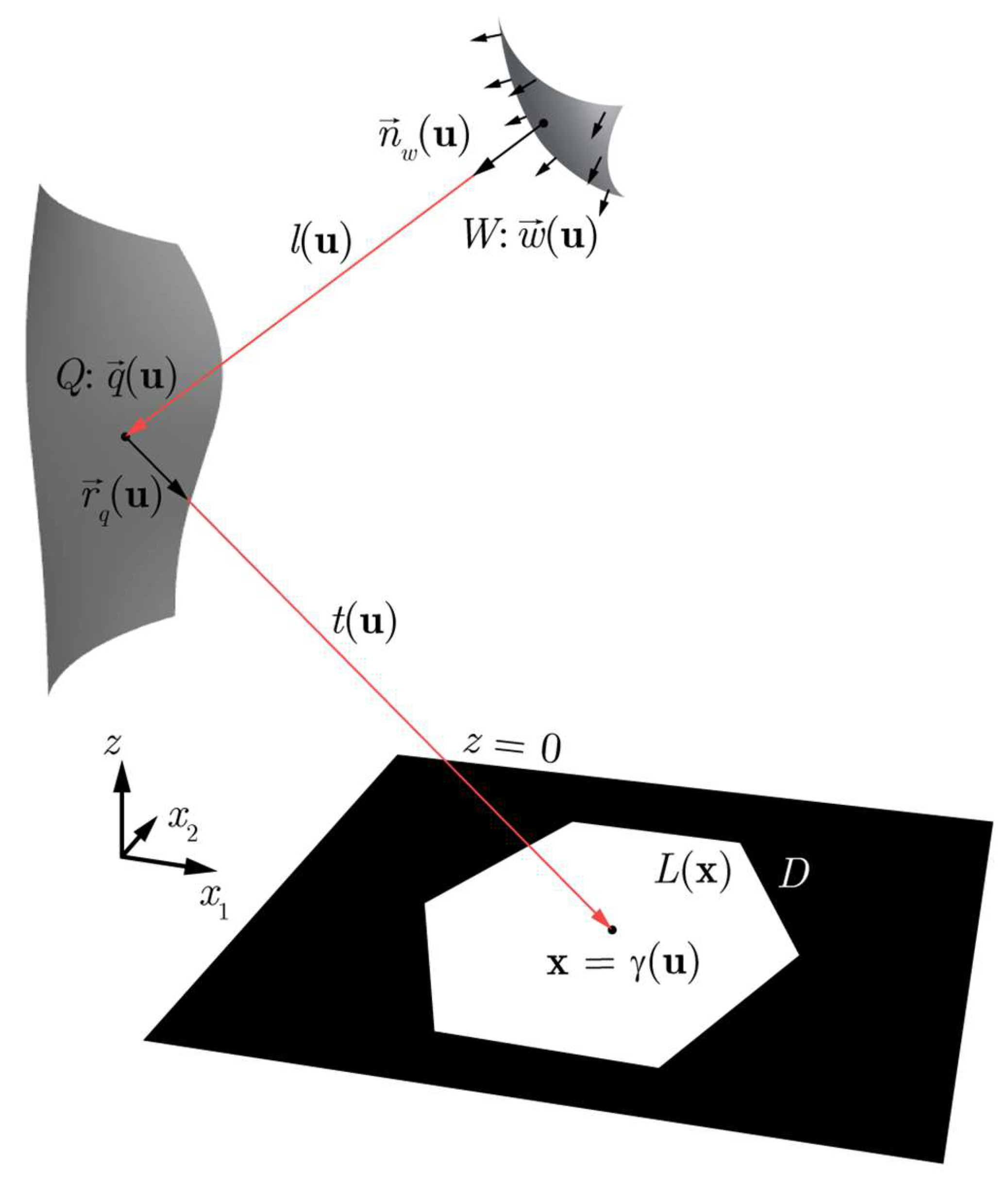
2.2. Envelope Representation of the Mirror Surface

The mirror surface can be represented as an envelope of a family of stigmatic surfaces focusing the incident light beam to the points of the target domain D [12,22,23,24,25,27]. Similar to Equation (1), the equation of a reflecting stigmatic surface focusing the incident beam to the point x = ( x 1 , x 2 ) D of the plane z = 0 can be written as
q s t ( u ; x ) = w ( u ) + l s t ( u ; x ) n w ( u ) ,
where l s t ( u ; x ) is the distance from the wavefront surface to the stigmatic surface along the ray propagation direction. Let us note that the coordinates of the point x = ( x 1 , x 2 ) D in Equation (6) are considered to be parameters. Let us define the function l s t ( u ; x ) in Equation (6) from the condition of a constant path length F ( x ) from the wavefront W of the incident beam to the focus x = ( x 1 , x 2 , 0 ) = ( x , 0 ) :
F ( x ) = l s t ( u ; x ) + q s t ( u ; x ) x = l s t ( u ; x ) + + ( w 1 ( u ) + n w , 1 ( u ) l s t ( u ; x ) x 1 ) 2 + ( w 2 ( u ) + n w , 2 ( u ) l s t ( u ; x ) x 2 ) 2 + ( w 3 ( u ) + n w , 3 ( u ) l s t ( u ; x ) ) 2 .
Since the function l s t ( u ; x ) also depends on the value F ( x ) defining the optical path length for a given point x = ( x 1 , x 2 ) , we will further write it in the form l s t ( u ; x , F ( x ) ) . From Equation (7), the function l s t ( u ; x , F ( x ) ) can be obtained as
l s t ( u ; x , F ( x ) ) = F 2 ( x ) ( w ( u ) x ) 2 F ( x ) + n W ( u ) ( w ( u ) x ) .
The equation of the envelope surface for the family of surfaces q s t ( u ; x ) with respect to the parameter x D is defined by Equation (6) and the following two equations [27,28]:
{ ( q s t , x 1 , q s t , u 1 , q s t , u 2 ) = 0 , ( q s t , x 2 , q s t , u 1 , q s t , u 2 ) = 0 ,
where q s t , x i = q s t ( u ; x ) / x i , i = 1 , 2 , q s t , u i = q s t ( u ; x ) / u i , i = 1 , 2 , and the parentheses denote the mixed product of the vectors. Substituting Equation (6) into Equation (9) and performing simple transformations, we obtain the envelope equation in the form
{ l s t , x 1 ( n W , w u 1 + l s t n W , u 1 , w u 2 + l s t n W , u 2 ) = 0 , l s t , x 2 ( n W , w u 1 + l s t n W , u 1 , w u 2 + l s t n W , u 2 ) = 0 ,
where l s t , x i = l s t ( u ; x , F ( x ) ) / x i , i = 1 , 2 . Note that the fulfillment of the conditions
{ l s t , x 1 ( u ; x , F ( x ) ) = 0 , l s t , x 2 ( u ; x , F ( x ) ) = 0
is sufficient for the fulfillment of the envelope Equation (10).
In order to obtain an explicit expression for the envelope, it is necessary to express from Equation (11) the variables ( x 1 , x 2 ) as functions of the variables ( u 1 , u 2 ) and substitute the obtained expressions to Equation (6). Note that at a fixed value of u = ( u 1 , u 2 ) G , Equation (11) corresponds to a critical point of the function l s t ( u ; x , F ( x ) ) with respect to the variables x 1 , x 2 . As in the works [12,14,22,29,30,31], in what follows, we will consider an envelope of a special kind, for which Equation (11) defines not only a critical point, but a minimum point. In this case, the functions x ( u ) = ( x 1 ( u ) , x 2 ( u ) ) satisfying Equation (11) will have the form
x = argmin x D l s t ( u ; x , F ( x ) ) .
From Equations (12), (11), and (6), it follows that the envelope equation has the form
q ( u ) = w ( u ) + l ( u ) n w ( u ) ,
where
l ( u ) = min x D l s t ( u ; x , F ( x ) ) = min x D F 2 ( x ) ( w ( u ) x ) 2 F ( x ) + n W ( u ) ( w ( u ) x ) .
It is easy to understand [11,12,13,14,22,29,31] that Equation (12) defines the ray mapping x = γ ( u ) implemented by the envelope surface. Note that the ray mapping and the envelope are completely defined by the function F ( x ) , which determines the optical path length from the wavefront W to the points of the domain D. This makes it possible to formulate the problem of designing a mirror that generates a prescribed irradiance distribution L ( x ) , x D in the plane z = 0 as a problem of calculating such a function F ( x ) , so that the corresponding ray mapping of Equation (12) satisfies the light flux conservation law defined by Equation (4) or Equation (5).

2.3. Supporting Quadric Method

In this subsection, we consider a version of the supporting quadric method (SQM) for the solution of the inverse problem of calculating a mirror that generates a prescribed irradiance distribution (Figure 1). Strictly speaking, the rigorous formulation of the SQM requires the introduction of the concept of the so-called weak solution, which makes it possible to correctly define the solution of the problem in this case, in which the ray mapping has discontinuities on a set of measure zero [15,17,29,31]. However, for the sake of simplicity, let us focus on the practical side of the method.
In the SQM, the prescribed continuous irradiance distribution L ( x ) , x D has to be approximated by a discrete distribution. Therefore, let us assume that in the domain D, a rectangular grid containing N cells D i , i = 1 , N ¯ is introduced, with the centers at the points x i , i = 1 , N ¯ . As a discrete approximation of the continuous distribution L ( x ) , x D , let us consider the following discrete distribution:
L d ( x ) = i = 1 N L i δ ( x x i ) ,
where δ ( x ) is the Dirac delta function, and L i = D i L ( x ) d x are the light flux values in the cells D i . For the discrete distribution of Equation (15), the function F ( x ) becomes a set of numbers F = { F 1 , , F N } , which we will refer to as the weights of the points x i , i = 1 , N ¯ . In this case, the envelope surface of Equations (13) and (14) turns into a piecewise smooth surface consisting of N segments of the stigmatic surfaces of Equations (6) and (8), focusing the incident beam to the points x i = ( x i , 0 ) , i = 1 , N ¯ . This surface is defined by Equation (13), where the function l ( u ) reads as
l ( u ) = min i l s t , i ( u ; x i , F i ) = min i F i 2 ( w ( u ) x i ) 2 F i + n w ( u ) ( w ( u ) x i ) .
The ray mapping implemented by this surface is defined by the equation
γ ( u ) = argmin x i l s t , i ( u ; x i , F i ) .
Since for a discrete distribution, the surface of Equations (13) and (16) is completely defined by the set of weights F = { F 1 , , F N } , the problem of generating a given discrete distribution of Equation (15) can be considered to be the problem of finding weights F = { F 1 , , F N } , which provide the generation of the required light flux values L i , i = 1 , N ¯ at the points x i , i = 1 , N ¯ .
Let us explain, how the light flux values at the points x i , i = 1 , N ¯ are related with the weights F = { F 1 , , F N } . For this, let us introduce the concept of the generalized Voronoi cell to define the “apertures” of the stigmatic surfaces in the domain G . Under generalized Voronoi cells with the weights F = { F 1 , , F N } , we will understand the subdomains C F ( x i ) G equal to the inverse images γ 1 ( x i ) , i = 1 , N ¯ . From Equation (17), it follows that the cells C F ( x i ) can be defined by the following condition: a point u G lies inside the cell C F ( x i ) if, and only if,
l s t , i ( u ; x i , F i ) l s t , j ( u ; x i , F j ) , j i .
The light flux Φ i focused on the point x i is calculated as an integral over the corresponding generalized Voronoi cell:
Φ i ( F 1 , , F N ) = C F ( x i ) I ( u ) d u = C F ( x i ) E ( u ) | w u 1 × w u 2 | d u .
According to Equation (19), the problem of finding the weights F = { F 1 , , F N } providing the required light flux values L i , i = 1 , N ¯ at the points x i , i = 1 , N ¯ can be considered to be the problem of solving the following system of nonlinear equations:
{ Φ 1 ( F 1 , , F N ) = L 1 , Φ n ( F 1 , , F N ) = L n .
Let us rewrite this system as
{ F 1 = F 1 + ε ( Φ 1 ( F 1 , , F N ) L 1 ) , F n = F n + ε ( Φ n ( F 1 , , F N ) L n ) .
Using the simple iteration method for solving the system (21), we obtain the following iterative algorithm for the calculation of the weight values:
F i k + 1 = F i k + ε ( Φ i ( F 1 k , , F N k ) L i ) , i = 1 , N ¯ ,
where the superscript k denotes the iteration number, and ε > 0 is the step of the iterative method.
Let us explain that the algorithm of Equation (22) updates the weights F = { F 1 , , F N } in the “right direction”. Assume that all the weights except the value F i are fixed. Let, at the k-th step of the iterative algorithm, the light flux Φ i ( F ) generated at the point x i be greater than the required one L i . In this case, the algorithm of Equation (22) increases the weight F i . Below, we demonstrate that l s t , i / F i 0 and, therefore, for all points u G the value l s t , i ( u ; x i , F i ) increases. As a result, the inequalities in Equation (18) hold for a smaller set of points u G , i.e., the cell C F ( x i ) decreases and, correspondingly, the generated light flux Φ i ( F ) also decreases. Similarly, one can show that if the light flux Φ i ( F ) generated at the point x i is smaller than the required one L i , then the algorithm of Equation (22) will decrease the weight F i . In this case, the size of the cell C F ( x i ) and, correspondingly, the generated light flux Φ i ( F ) will increase.
Let us now prove the following inequality used above:
l s t , i ( u ; x i , F i ) F i = F i ( F i 2 ( w ( u ) x i ) 2 F i + n w ( u ) ( w ( u ) x i ) ) 0 .
By expanding the right-hand side of Equation (23), we obtain
l s t , i ( u ; x i , F i ) F i = ( F i + n w ( u ) ( w ( u ) x i ) ) 2 ( n w ( u ) ( w ( u ) x i ) ) 2 + ( w ( u ) x i ) 2 ( F i + n w ( u ) ( w ( u ) x i ) ) 2 .
Let us consider the last two terms of the numerator:
( w ( u ) x i ) 2 ( n w ( u ) ( w ( u ) x i ) ) 2 = w ( u ) x i 2 w ( u ) x i 2 cos 2 φ 0 ,
where φ is the angle between the vectors n w ( u ) and w ( u ) x i . Taking into account Equation (25), it follows from Equation (24) that the inequality of interest (Equation (23)) holds.
To conclude this section, let us note that in a practical implementation of the iterative algorithm of Equation (22), the ray-tracing method is used for calculating the values Φ i ( F ) . In this case, the incident beam is approximated by a set of N t r rays going out of the nodes of a certain grid u j , j = 1 , N t r ¯ on the surface of the wavefront W. These rays “carry” the light flux values I j , j = 1 , N t r ¯ , which are proportional to the values of the irradiance of the incident beam at the nodes of the grid. According to Equations (16) and (17), for each ray going out of the point u j , the index of the surface i ( j ) = arg min i ( l s t , i ( u ; x i , F ) ) is found, which the ray “meets” first. This ray is directed to the corresponding point x i of the generated distribution. Then, at the points x i , the light flux values are calculated as the sums of the light fluxes of the rays arriving at these points.

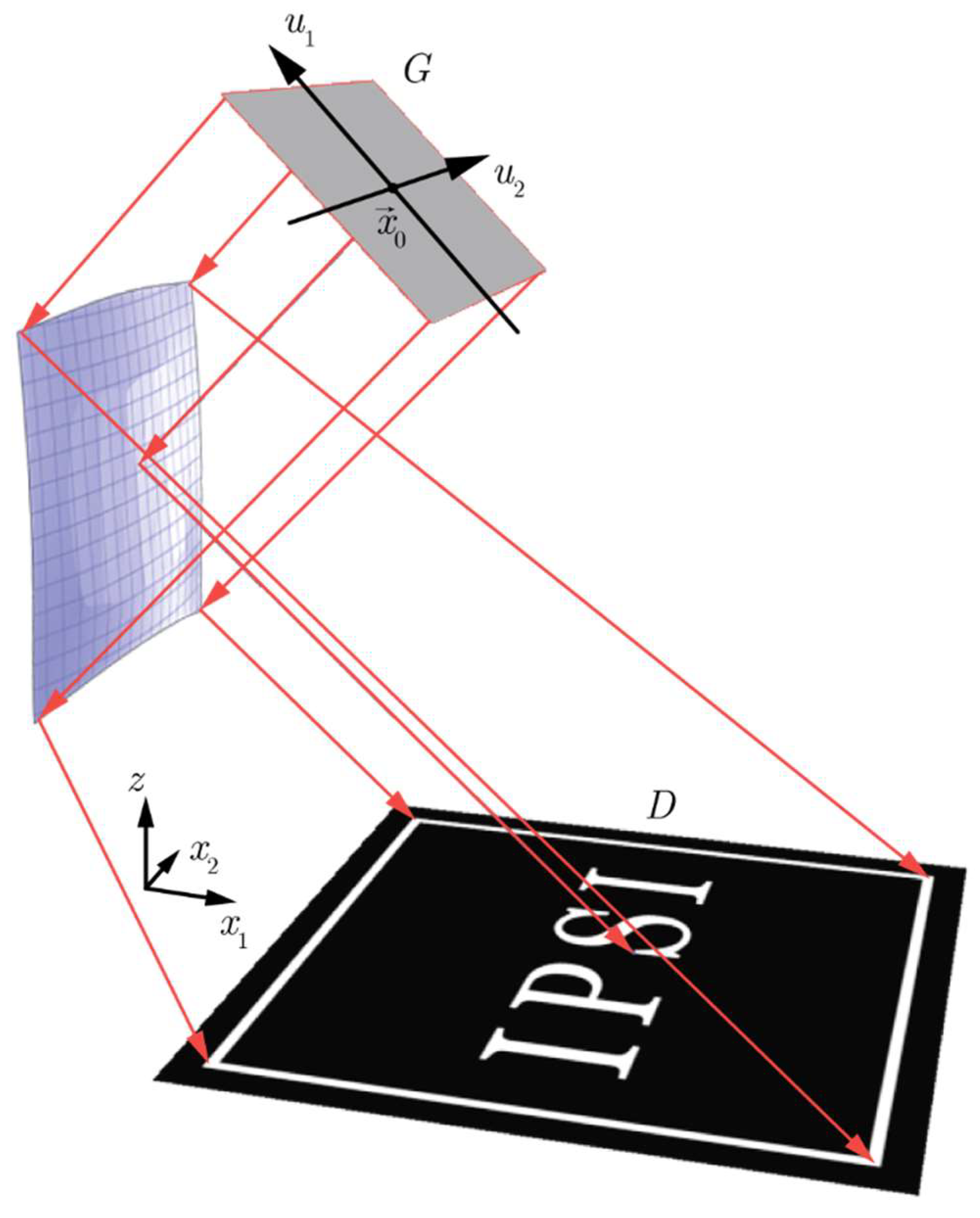
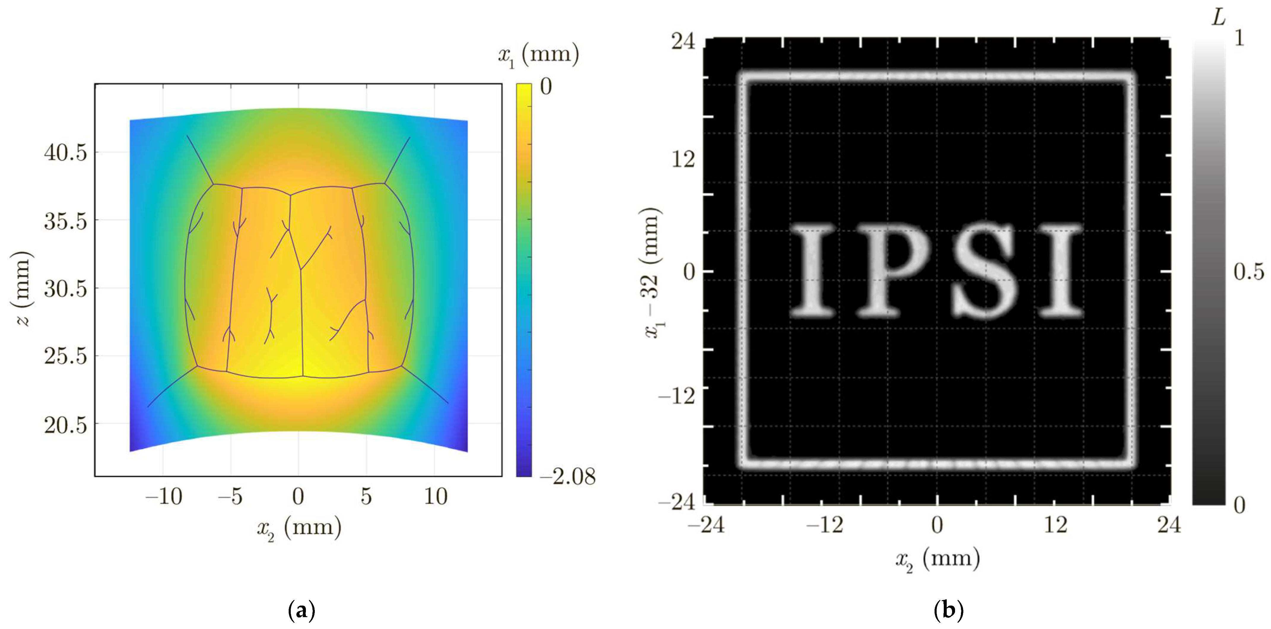
3. Results and Discussion

The SQM for designing mirrors considered in the previous section was implemented in a practically important case of an incident beam with a plane wavefront. In the example considered below, the wavefront surface W is the plane
n w ( x x 0 ) = 0 ,
where n w = ( 1 , 0 , 1 ) / 2 and x 0 = ( 10   mm ,   0 ,   40   mm ) . Equation (26) can be written in the parametric form:
w ( u ) = x 0 + u 1 k 1 + u 2 k 2 ,
where k 1 = ( 1 , 0 , 1 ) 1 / 2 , k 2 = ( 0 , 1 , 0 ) are the unit vectors of the Cartesian coordinate system u = ( u 1 , u 2 ) in the plane W with the origin at the point x 0 (Figure 2). It can be easily understood that in the case of a plane wavefront of the incident beam, the stigmatic surfaces of Equations (6) and (8) that focus the incident light beam to the points of the target domain correspond to paraboloids of revolution. The axes of the paraboloids are parallel to the normal vector n w to the wavefront, whereas their foci lie in the target domain D. Note that in the plane wavefront case, the only simplification in the general “envelope representation” of the mirror surface (Equations (13) and (14)) consists of the fact that the normal vector n w ( u ) does not depend on the point u .
Let the incident beam be defined in a rectangular domain G = { u | | u 1 | < 12.5   mm , | u 2 | < 8.5   mm } and have a constant irradiance distribution E ( u ) = E 0 , u G (Figure 2). For this incident beam, we designed a mirror generating in the plane z = 0 an irradiance distribution L ( x ) , x D in the form of framed letters “IPSI” (the abbreviation of the Image Processing Systems Institute) on a zero background (Figure 2). The outer boundary of the frame coincides with the boundary of the square region D = { x | | x 1 32   mm | < 20   mm , | x 2 | < 20   mm } .
In accordance with the version of the SQM considered in the previous section, the required irradiance distribution L ( x ) , x D (Figure 2) was approximated by a discrete distribution containing N = 29,403 points. The points were located at the nodes of a square grid (grid step Δ = 0.09 mm) covering the domain D. The calculation of the mirror surface was carried out using the iterative algorithm of Equation (22). At each iteration of the method, the light flux values at the points of the discrete distribution were calculated using the ray-tracing technique, and then the weight values F i were corrected using Equation (22). As the initial weight values for starting the iterative process, constant values were chosen: F i = F 0 = 40 2 56.6   mm , i = 1 , N ¯ . The F 0 value corresponds to the optical path length of the “central” ray coming out of the point x 0 reflected from the plane x 1 = 0 . In this case, the initial mirror surface is given by Equations (13), (16), and (27).
In the ray-tracing method used at each iteration for calculating the light flux values Φ i , the incident beam was approximated by 3 N rays defined on a square grid. In the calculation, about 35,000 iterations were performed. The total computation time on a modern desktop PC (Core i9-7940X CPU) was about three hours.
The three-dimensional image of the designed mirror is shown in Figure 2. On the surface of the mirror, “sharp bends” (derivative discontinuities) can be seen. The presence of the sharp bends is caused by the discontinuous character of the ray mapping, corresponding to the generated “discontinuous” irradiance distribution in the form of separate letters and a frame on a zero background. The derivative discontinuities are additionally shown with blue lines in Figure 3a. This figure shows the calculated mirror as the function x 1 = x 1 ( x 2 , z ) describing the “depth” of the mirror surface along the x 1 axis. Figure 3b shows the irradiance distribution generated by the mirror in the plane z = 0 . This distribution was calculated using the commercially available ray-tracing software TracePro [32], and with a good accuracy coincides with the required distribution. The normalized root mean square deviation of the calculated distribution (Figure 3b) from the required one (Figure 2) amounts to 8.1%.
The presented example demonstrates one of the advantages of the proposed method, which consists of the capability to calculate continuous piecewise smooth surfaces for implementing discontinuous ray mappings. In this case, the known methods based on numerical solution of NDEs of an elliptic type [1,2,3,4,5,6,7,8,9,10] are either inapplicable or numerically unstable.
The designed mirror was fabricated using the milling technique with a three-axis machining center, Haas Minimill. As a blank for the mirror, a silver plate was used. The photograph of the two fabricated mirrors is shown in Figure 4. In the right-hand side of the photograph, a mirror after the milling process is shown, whereas the left-hand side shows a mirror after the polishing process, which was applied in order to remove the cutter marks.
Figure 4b shows the irradiance distribution generated by the mirror when illuminated by a handheld flashlight. The dimensions and shape of the generated distribution qualitatively correspond to the calculated distribution shown in Figure 3b and confirm the correctness of the performed calculations. The blurring of the letters and artifacts in the generated distribution are caused by the fabrication imperfections and errors in the positioning of the illuminating beam, as well as its deviation from the beam with a plane wavefront and uniform irradiance distribution used in the mirror design. However, the authors believe that the presented example demonstrates the “robustness” of the mirror designed using the proposed version of the SQM to the fabrication errors and the variations in the incident beam. This makes it possible to use such mirrors in “out-of-laboratory conditions”, for example, when creating jewelry exhibiting interesting optical effects. In particular, the mirrors shown in Figure 4a are prototypes for cufflinks.

4. Conclusions

We proposed a version of the supporting quadric method for calculating a mirror that generates a prescribed irradiance distribution in the near field for an incident beam with an arbitrary wavefront. In the method, the mirror surface is represented as a set of segments of stigmatic surfaces focusing the incident beam to the points of the required distribution. The parameters of the stigmatic surfaces are calculated using an iterative method, which can be considered to be a simple iteration method for solving a system of nonlinear equations.
Using the developed method, a mirror generating an irradiance distribution in the form of framed letters “IPSI” on a zero background was designed for a practically important particular case of an incident beam with a plane wavefront. This example demonstrates the possibility of using the method for designing mirrors with continuous piecewise smooth surfaces for implementing discontinuous ray mappings. The numerical simulation results obtained using the commercial software TracePro demonstrate the good quality of the generated distribution. The designed mirror was fabricated using the milling technique and was qualitatively investigated in a proof-of-concept optical experiment. The experimental results confirm the correctness of the proposed approach and demonstrate the manufacturability of the mirrors designed using the developed method.

Author Contributions

Conceptualization, L.L.D.; methodology, A.A.M., E.V.B. and L.L.D.; software, E.V.B. and D.A.B.; validation, E.V.B., G.J.K. and V.I.S.; investigation, E.V.B., E.A.B. and G.J.K.; resources, G.J.K. and V.I.S.; writing—original draft preparation, L.L.D., A.A.M. and E.A.B.; writing—review and editing, L.L.D., E.A.B. and D.A.B.; visualization, D.A.B., E.V.B. and E.A.B.; supervision, N.L.K.; project administration, N.L.K.; funding acquisition, L.L.D. and N.L.K. All authors have read and agreed to the published version of the manuscript.

Funding

This work was supported by the Russian Science Foundation (project 18-19-00326, development of the supporting quadric method in the general case of an incident beam with an arbitrary wavefront, design and fabrication of the mirror using the milling technique) and by the Ministry of Science and Higher Education of the Russian Federation (state assignment to the FSRC “Crystallography and Photonics” RAS (agreement 007-GZ/Ch3363/26), technical support in the CAD design and additional processing (polishing) of the mirror surface; and state assignment for research to Samara University (laboratory “Photonics for Smart Home and Smart City”, project FSSS-2021-0016), software implementation of the supporting quadric method).

Data Availability Statement

The data that support the presented results are available from the corresponding author upon reasonable request.

Conflicts of Interest

The authors declare no conflict of interest.

References

  1. Wu, R.; Feng, Z.; Zheng, Z.; Liang, R.; Benítez, P.; Miñano, J.C.; Duerr, F. Design of freeform illumination optics. Laser Photon. Rev. 2020, 12, 1700310. [Google Scholar] [CrossRef]
  2. Ries, H.; Muschaweck, J. Tailored freeform optical surfaces. J. Opt. Soc. Am. A 2002, 19, 590–595. [Google Scholar] [CrossRef]
  3. Wu, R.; Xu, L.; Liu, P.; Zhang, Y.; Zheng, Z.; Li, H.; Liu, X. Freeform illumination design: A nonlinear boundary problem for the elliptic Monge–Ampére equation. Opt. Lett. 2013, 38, 229–231. [Google Scholar] [CrossRef]
  4. Wu, R.; Zhang, Y.; Sulman, M.M.; Zheng, Z.; Benítez, P.; Miñano, J.C. Initial design with L2 Monge-Kantorovich theory for the Monge–Ampère equation method in freeform surface illumination design. Opt. Express 2014, 22, 16161–16177. [Google Scholar] [CrossRef]
  5. Wu, R.; Chang, S.; Zheng, Z.; Zhao, L.; Liu, X. Formulating the design of two freeform lens surfaces for point-like light sources. Opt. Lett. 2018, 43, 1619–1622. [Google Scholar] [CrossRef]
  6. Brix, K.; Hafizogullari, Y.; Platen, A. Designing illumination lenses and mirrors by the numerical solution of Monge–Ampère equations. J. Opt. Soc. Am. A 2015, 32, 2227–2236. [Google Scholar] [CrossRef] [Green Version]
  7. Brix, K.; Hafizogullari, Y.; Platen, A. Solving the Monge–Ampère equations for the inverse reflector problem. Math. Model. Methods Appl. Sci. 2015, 25, 803–837. [Google Scholar] [CrossRef] [Green Version]
  8. Prins, C.R.; ten Thije Boonkkamp, J.H.M.; van Roosmalen, J.; IJzerman, W.L.; Tukker, T.W. A Monge–Ampère-solver for free-form reflector design. SIAM J. Sci. Comput. 2014, 36, B640–B660. [Google Scholar] [CrossRef] [Green Version]
  9. Shen, F.; Yang, L.; Hu, G.; Ding, Z.; She, J.; Zhang, Y.; Wu, R. Freeform and precise irradiance tailoring in arbitrarily oriented planes. Opt. Express 2021, 29, 42844–42854. [Google Scholar] [CrossRef]
  10. Bösel, C.; Gross, H. Ray mapping approach for the efficient design of continuous freeform surfaces. Opt. Express 2016, 24, 14271–14282. [Google Scholar] [CrossRef] [PubMed] [Green Version]
  11. Doskolovich, L.L.; Bykov, D.A.; Mingazov, A.A.; Bezus, E.A. Optimal mass transportation and linear assignment problems in the design of freeform refractive optical elements generating far-field irradiance distributions. Opt. Express 2019, 27, 13083–13097. [Google Scholar] [CrossRef]
  12. Doskolovich, L.L.; Bykov, D.A.; Andreev, E.S.; Byzov, E.V.; Moiseev, M.A.; Bezus, E.A.; Kazanskiy, N.L. Design and fabrication of freeform mirrors generating prescribed far-field irradiance distributions. Appl. Opt. 2020, 59, 5006–5012. [Google Scholar] [CrossRef] [PubMed]
  13. Bykov, D.A.; Doskolovich, L.L.; Bezus, E.A. Multiscale approach and linear assignment problem in designing mirrors generating far-field irradiance distributions. Opt. Lett. 2020, 45, 3549–3552. [Google Scholar] [CrossRef]
  14. Doskolovich, L.L.; Bykov, D.A.; Andreev, E.S.; Bezus, E.A.; Oliker, V. Designing double freeform surfaces for collimated beam shaping with optimal mass transportation and linear assignment problems. Opt. Express 2018, 26, 24602–24613. [Google Scholar] [CrossRef] [PubMed]
  15. Caffarelli, L.; Kochengin, S.; Oliker, V. On the numerical solution of the problem of reflector design with given far-field scattering data. Contemp. Math. 1999, 226, 13–32. [Google Scholar]
  16. Kochengin, S.; Oliker, V. Computational algorithms for constructing reflectors. Comput. Vis. Sci. 2003, 6, 15–21. [Google Scholar] [CrossRef]
  17. Oliker, V. Mathematical aspects of design of beam shaping surfaces in geometrical optics. In Trends in Nonlinear Analysis; Kirkilionis, M., Krömker, S., Rannacher, R., Tomi, F., Eds.; Springer: Berlin/Heidelberg, Germany, 2003; pp. 193–224. [Google Scholar]
  18. Fournier, F.R.; Cassarly, W.J.; Rolland, J.P. Fast freeform reflector generation using source-target maps. Opt. Express 2010, 18, 5295–5304. [Google Scholar] [CrossRef] [Green Version]
  19. Michaelis, D.; Schreiber, P.; Brauer, A. Cartesian oval representation of freeform optics in illumination systems. Opt. Lett. 2011, 36, 918–920. [Google Scholar] [CrossRef]
  20. Oliker, V. Controlling light with freeform multifocal lens designed with supporting quadric method (SQM). Opt. Express 2017, 25, A58–A72. [Google Scholar] [CrossRef]
  21. Doskolovich, L.L.; Moiseev, M.A.; Bezus, E.A.; Oliker, V. On the use of the supporting quadric method in the problem of the light field eikonal calculation. Opt. Express 2015, 23, 19605–19617. [Google Scholar] [CrossRef]
  22. Mingazov, A.A.; Bykov, D.A.; Bezus, E.A.; Doskolovich, L.L. On the use of the supporting quadric method in the problem of designing double freeform surfaces for collimated beam shaping. Opt. Express 2020, 28, 22642–22657. [Google Scholar] [CrossRef] [PubMed]
  23. Glimm, T.; Oliker, V. Optical design of single reflector systems and the Monge-Kantorovich mass transfer problem. J. Math. Sci. 2003, 117, 4096–4108. [Google Scholar] [CrossRef]
  24. Wang, X.-J. On design of a reflector antenna II. Calc. Var. Partial. Differ. Equ. 2004, 20, 329–341. [Google Scholar] [CrossRef]
  25. Glimm, T.; Oliker, V. Optical design of two-reflector systems, the Monge-Kantorovich mass transfer problem and Fermat’s principle. Indiana Univ. Math. J. 2004, 53, 1255–1277. [Google Scholar] [CrossRef] [Green Version]
  26. Doskolovich, L.L.; Mingazov, A.A.; Byzov, E.V.; Skidanov, R.V.; Ganchevskaya, S.V.; Bykov, D.A.; Bezus, E.A.; Podlipnov, V.V.; Porfirev, A.P.; Kazanskiy, N.L. Hybrid design of diffractive optical elements for optical beam shaping. Opt. Express 2021, 29, 31875–31890. [Google Scholar] [CrossRef]
  27. Doskolovich, L.L.; Andreev, E.S.; Kharitonov, S.I.; Kazansky, N.L. Reconstruction of an optical surface from a given source-target map. J. Opt. Soc. Am. A 2016, 33, 1504–1508. [Google Scholar] [CrossRef]
  28. Zalgaller, V.A. The Theory of Envelopes; Nauka: Moscow, Russia, 1975. [Google Scholar]
  29. Bykov, D.A.; Doskolovich, L.L.; Mingazov, A.A.; Bezus, E.A. Optimal mass transportation problem in the design of freeform optical elements generating far-field irradiance distributions for plane incident beam. Appl. Opt. 2019, 58, 9131–9140. [Google Scholar] [CrossRef]
  30. Glimm, T. A rigorous analysis using optimal transport theory for a two-reflector design problem with a point source. Inverse Probl. 2010, 26, 045001. [Google Scholar] [CrossRef]
  31. Doskolovich, L.L.; Mingazov, A.A.; Bykov, D.A.; Andreev, E.S.; Bezus, E.A. Variational approach to calculation of light field eikonal function for illuminating a prescribed region. Opt. Express 2017, 25, 26378–26392. [Google Scholar] [CrossRef]
  32. Tracepro, Illumination and Non-Imaging Optical Design & Analysis Tool. Available online: https://lambdares.com/tracepro/ (accessed on 29 December 2021).
Figure 1. Geometry of the mirror design problem.
Photonics 09 00118 g001
Figure 2. Geometry of the problem of designing a mirror for generating an irradiance distribution in the form of framed letters “IPSI” for an incident beam with a plane wavefront. The dimensions of the input beam, freeform mirror, and the generated distribution correspond to the considered example up to a scale factor.
Photonics 09 00118 g002
Figure 3. (a) Surface of the mirror generating an irradiance distribution in the form of framed letters “IPSI” shown as “depth” function along the x 1 axis. Blue lines show the “sharp bends” of the surface (derivative discontinuities). (b) Normalized irradiance distribution generated by the mirror calculated using TracePro.
Photonics 09 00118 g003
Figure 4. (a) Surface of the fabricated mirror before (right) and after (left) polishing. (b) Demonstration of the performance of the fabricated mirror.
Photonics 09 00118 g004
Publisher’s Note: MDPI stays neutral with regard to jurisdictional claims in published maps and institutional affiliations.

