Article

Active Optics—Advances of Cycloid-like Variable Curvature Mirrors for the VLTI Array

by
Gerard Rene Lemaitre
1,2,*,
Pascal Vola
1,3,
Patrick Lanzoni
1,2,
Silvio Mazzanti
1,
Frederic J. Dérie
4 and
Frederic Y. Gonté
4
1
Laboratoire d’Astrophysique de Marseille—LAM, 38 Rue Frédéric Joliot-Curie, 13388 Marseille, France
2
Aix Marseille Université—AMU, Campus Pharo, 58 Boulevard Charles Livon, 13007 Marseille, France
3
Centre National de la Recherche Scientifique—CNRS, Délégation Provence et Corse, Chemin Joseph Aiguier, 13009 Marseille, France
4
European Southern Observatory—ESO, Karl Schwarzschild-Str. 2, 85748 Garching, Germany
*
Author to whom correspondence should be addressed.
Photonics 2022, 9(2), 66; https://doi.org/10.3390/photonics9020066
Submission received: 6 December 2021 / Revised: 17 January 2022 / Accepted: 18 January 2022 / Published: 26 January 2022
(This article belongs to the Special Issue Active Optics)

Abstract

:
Elasticity theory and active optics led us to the discovery of three geometrical configurations of variable curvature mirrors (VCMs) that are either cycloid-like or tulip-like thickness distributions. Cycloid-like VCMs are generated by a uniform load—air pressure—applied over the mirror rear surface, and reacts without any bending moment along its circular contour. This particular VCM configuration is of practical interest because it smoothly generates accurate optical curvatures, varying from plane at rest to spherical curvatures up to f/2.9 over 16-mm aperture under 6.5-bar air pressure. Starting from the thin plate theory of elasticity and modeling with NASTRAN finite element analysis, one shows that 3-D optimizations—using a non-linear static flexural option—provide an accurate cycloid-like thickness distribution. VCM elasticity modeling in quenched stainless steel–chromium substrates allows the obtaining of diffraction-limited optical surfaces: Rayleigh’s criterion is achieved over a zoom range from flat to f/3.6 over 13-mm clear aperture up to 6-bar loading. These VCMs were originally developed and built at the Marseille Observatory in 1975 and implemented as a cat’s-eye mirror of IR Fourier-transform interferometers for laboratory recording of fast events in gas molecular spectroscopy. Later, for high-angular resolution astronomy with the ESO VLTI array—an interferometer made of 8 m Unit Telescopes (UTs) and 1.8 m Auxiliary Telescopes (ATs)—such VCMs were inevitable components to provide in a 3″ co-phased field-of-view since 1998. They were implemented (1) as cat’s eye mirrors of the height delay-lines beam recombination lab and (2) as ATs mirror-pair for output pupil conjugation of the movable x–y baseline. From the ESO-AMU approved convention of making 10 VCM spares up to 2024, the present modeling should provide a diffraction-limited extended field-of-view. It is pure coincidence that present results from modeling with an outer collarette are identical to results from analytic theory without collarette.

1. Introduction

Geometrical deformable configurations able to generate variable curvature mirrors (VCMs) were discovered by Lemaitre in 1976 [1]. Three configurations were derived from elasticity theory of small deformations of thin plates that have variable thickness distributions (VTD). Such VCMs—sometime called zoom mirrors—have either a cycloid-like form or tulip-like form thickness distributions.
The cycloid-like form manifold requires a uniform load—i.e., a gas or fluid pressure—applied over the mirror back surface that reacts without any bending moment along its circular contour. This VCM configuration is of practical interest because it can easily generate accurate optical curvatures varying from the plane at rest up to f/3.5 or f/3 when under stress.
The only other manifolds are two tulip-like forms that require, for static equilibrium, a combination of two sets of forces: a central axial force, a uniform load applied over the back surface, and an axial perimeter ring force. These VCM configurations may also provide a large zoom range up to f/3.5 or f/3 when under stress.
For such a large zoom range, Ferrari & Lemaitre [2] and Ferrari [3] carried out analytic investigations with the elasticity theory of large deflections of the plates. This theory takes into account the stresses at the middle surface of the plate. A review of both small and large deflection theories, and the construction results obtained with VCMs can be found in Astronomical Optics and Elasticity Theory—Active Optics Methods by Lemaitre [4].
These developments, carried out at the Marseille Observatory, which later merged at LAM, were applied to the construction of cycloid-like form VCMs:
  • for the Bellevue-CNRS lab and LPMA-Jussieu-Université lab as a cat’s-eye mirror of two-arm IR Fourier-transform interferometers, originally by Connes [5] and, subsequently, as a fast event recording with the large molecular spectroscopy interferometer by Camy-Peyret, S. Payan et al. [6],
  • for the CERGA-GI2T two-mirror 1.5-m telescope array by Labeyrie [7], including a cat’s-eye mirror mounted on a delay line at the REGAIN interferometer by Mourard, Thureau et al. [8],
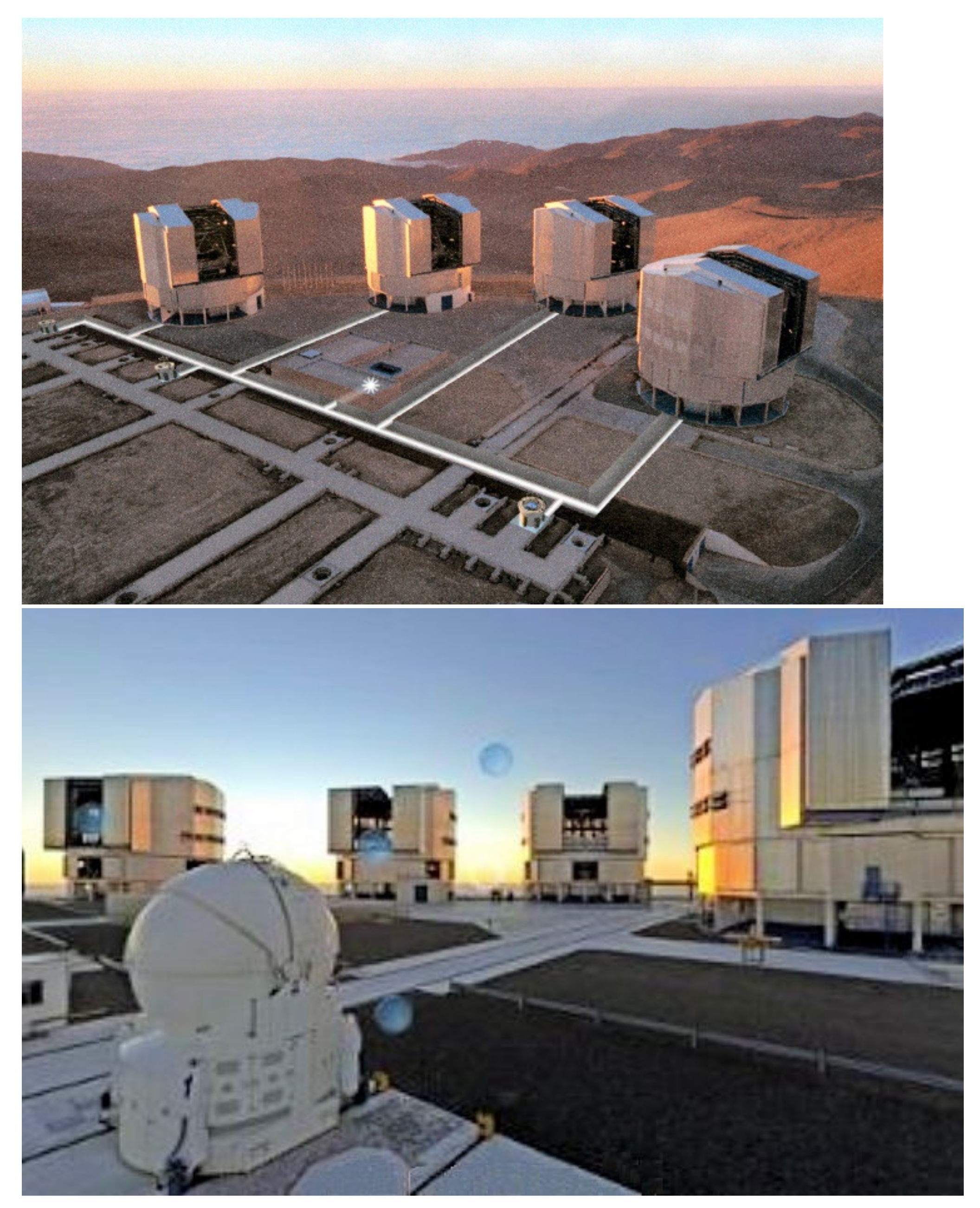
  • for the ESO-VLTI high-angular resolution astronomy, as the cat’s-eye mirrors of delay lines beam the recombination of the four 8-m telescopes (UT) and four 1.8-m telescopes (AT)—8 VCMs—as the extended-field-of-view system, and as the mirror-pair system. The AT x–y positions require output pupil conjugations of an observed object and a reference star—8 VCMs—for the central lab input pupil. The field-of-view considerations of the Paranal VLTI array were initiated by Beckers [9,10], and its development by von der Luehe et al. [11] and Glindemann et al. [12]. In addition to the on-axis cophasing by delay-lines, cat’s eye mirrors, i.e., VCMs realizing the cophasing of the field of view up to 3 arcsec. Dérie et al. [13], Koehler [14], and Gonté et al. [15] developed the delay-line telescope systems with the implementation of 16 VCMs.
In order to improve the mechanical design of cycloid-like VCMs, we presently show, from modeling with MSC-NASTRAN finite element analysis (FEA) code, as performed by one of us (Vola, in this paper), that 3-D optimizations with the non-linear static solution sequence SOL 106 can provide an accurate cycloid-like thickness distribution. The elasticity design of such VCM metal substrates allows the obtaining of diffraction-limited optical surfaces over a zoom range from a flat surface at rest to a convex surface when actively bent.
First-order modes of the triangle optical matrix, characterizing a wavefront shape are the curvature mode (Cv-1) and tilt mode (Tilt-1). These are the two fundamental modes involved in Gaussian optics. As a tilt mode is trivially obtained by a global rotation of a rigid substrate, investigations to achieve elastic deformation modes only reduce to deformable mirrors generating a Cv-1 curvature mode.
Let us denote z(r), the figure achieved by the flexure of a circular plate, which is flat at rest. In thin plate theory of small deformations, the Cv-1 curvature mode is represented by a parabolic flexure
z = A 20 r 2 1 2 R r 2 ,
where A20 is a constant and 1/R is the variable optical surface curvature.
One describes hereafter the two classes of thickness that can provide a curvature mode Cv 1 with the thin plate theory. These are constant thickness distribution (CTD) and variable thickness distribution (VTD) ([4] chapter 2).

2. Thin Circular Plate VCMs and Small Deformation Theory

Let us consider a plane circular plate—holed or plain—with a constant thickness, t, having a rigidity, D, classically expressed by
D = E t 3 / [ 12 ( 1 ν 2 ) ]
where E and ν are the Young modulus and Poisson’s ratio, respectively. If an external pair of concentric circle forces or a bending moment are applied to the perimeter region without a surface load (i.e., q = 0), then bilaplacian Poisson’s equation with respect to the flexure z of the plate is
2 2 z r = 0 ,
whose general solution
z = A 40 r 4 + B 20 + C 20 ln r + D 20 r 2 + E 20 r 2 ln r
contains the curvature term D20. The external forces taken into consideration by the bilaplacian can be a central one, a uniform distribution of forces onto a concentric circle, and uniform radial moments onto the inner and outer edges. Choosing the deformation origin at the plate vertex leads to set B20 = 0.

2.1. VCM of Constant Thickness Distribution—CTD

Considering the case of plain plates, flexural curvature modes Cv-1 for constant thickness plates (CTDs) require radial bending moments distributed at the contour. For instance, in practical applications, alternative configurations can be obtained by use of an outer built-in ring with two concentric and opposite axial ring forces (Figure 1). However, this CTD class is more difficult to generate than the variable thicknesses shown next.

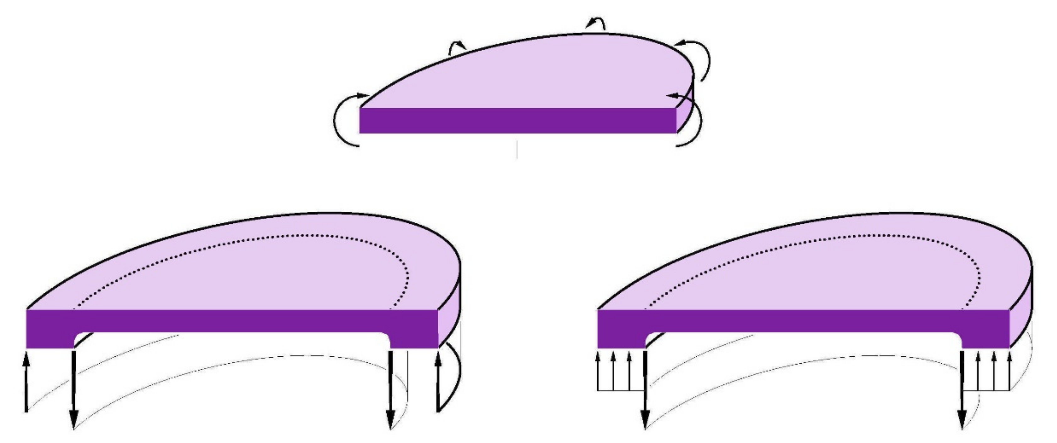
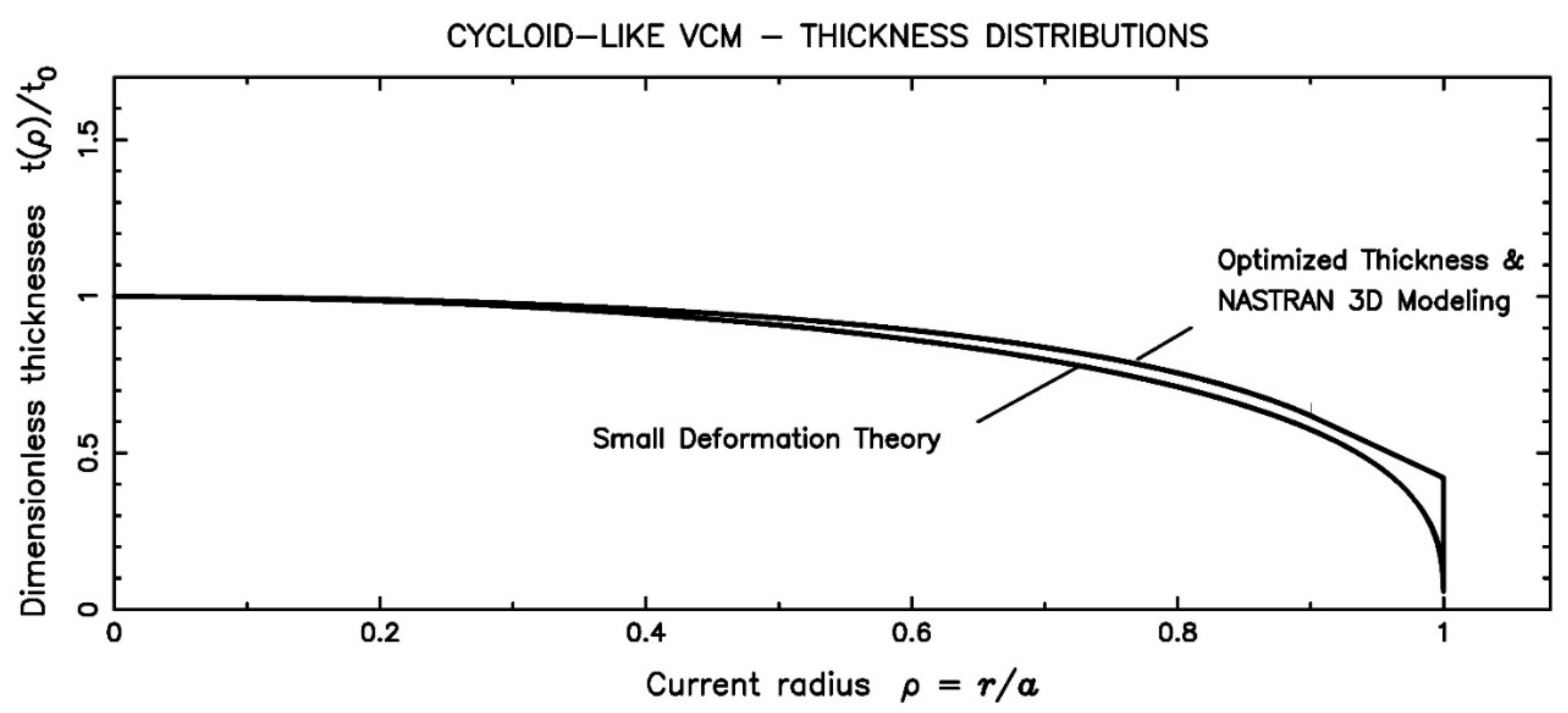
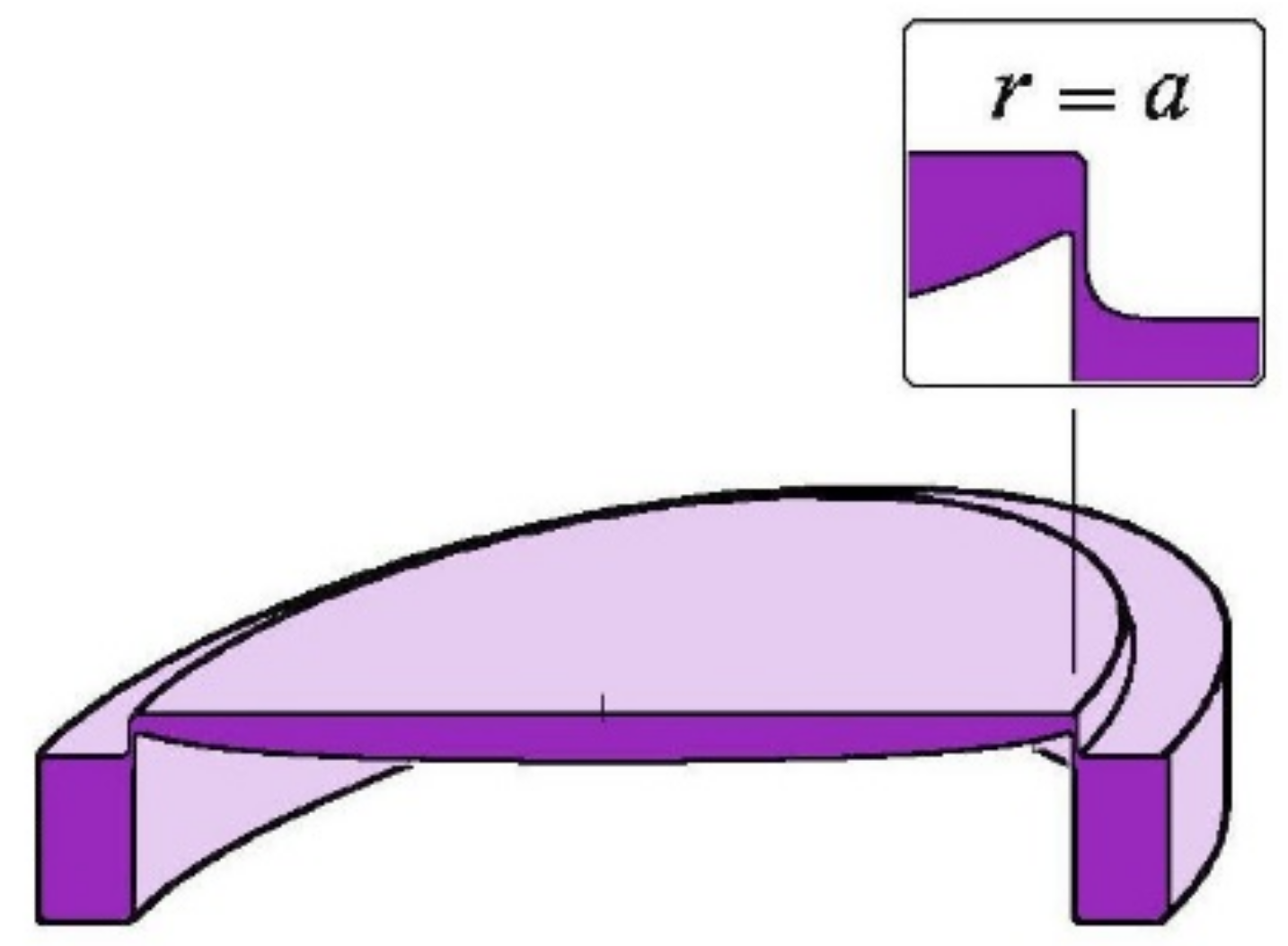
2.2. Plates of Variable Thickness Distribution—VTD—Cycloid-like Form—Tulip-like Forms

One summarizes here results obtained by Lemaitre [1,4] from the thin plate theory, that led to variable thickness distributions (VTDs) for the active optics mirrors, i.e. VCMs.
Starting from the definitions of radial and tangential bending moments, Mr and Mt respectively, and denoting Qr the shearing force, these variables provides the static equilibrium of a plate element. After substitution, the resulting equation is
D d d r 2 z + d 2 z d r 2 + ν r d z d r d D d r = Q r
where the rigidity express D r = E t r 3 / [ 12 ( 1 ν 2 ) ] and laplacian ∇2z = 4 A 20 from Equation (1). The shearing force Q r depends on each cases hereafter. Three VTDs associated to external loads are able to generate, actively, the curvature mode Cv-1. Each of them requires a particular shearing force.
  • VTD Type 1—Uniform loading and reaction at edge:
A uniform load q is applied all over the surface of the substrate in the reaction at the edge r = a. At a current radius r of the substrate, the shearing force Qr is defined by the equilibrium πr2q + 2πrQr = 0 of the inner element to r, that is
Q r = 1 2 q r   ,
and after substitution, we obtain the rigidity
D = q R 4 1 + ν c o n s t a n t r 2 .
The interest of VTDs is to avoid the use of moments at the boundaries. We can select a null bending moment at the edge, Mr(a) = 0. This is satisfied if the rigidity at the edge is D(a) = 0. Therefore, the rigidity is
D = q a 2 R 4 1 + ν 1 r 2 a 2   ,
and then the thickness distribution is
t = 3 1 ν q R E a   1 r 2 a 2 1 / 3 a   .  
Due to the smoothly decreasing profile for low values of r, and of a vertical tangents at the substrate edge r = a, we call this thickness distribution a cycloid-like form.
CONCLUSION—Cycloid-like form class or VTD Type 1:
Variable curvature mirrors are obtained by the uniform loading, q, and the reaction force at the edge that provides a cycloid-like thickness of t = T20t0such as
T 20 = 1 r 2 a 2 1 / 3             w i t h               t 0 a = 3 1 ν q R E a 1 / 3 ,
where 1/R = 2A20 is the curvature of the deformation, and the product qR is negative (Figure 2Up-Left).
  • VTD Type 2—Axial force at center and reaction at edge:
The substrate is deflected by an axial force F applied to its center that gives rise to a uniform reaction F at the edge. If we consider an equivalent uniform load, q, applied to its entire surface, we can define the central force by F = πa2q, then the associated shearing force Qr satisfies πa2q + 2πr Qr = 0. Similarly, as in the previous configuration, we select a null bending moment at the edge by selecting D(a) = 0. From integration, constant = ln a. The rigidity is
D = q a 2 R 4 1 + ν   ln r 2 a 2   .
Due to an infinite thickness at r = 0 and vertical tangents at the substrate edge, we call this thickness distribution a tulip-like form.
CONCLUSION—Tulip-like form class or VTD Type 2:
Variable curvature mirrors are obtained by an axial force, F, at the center and the reaction at the edge provides a tulip-like thickness, t = T20, t0 such as
T 20 = ln r 2 a 2 1 / 3         w i t h           t 0 a = 3 1 ν F R π E a 3 1 / 3 ,
where 1/R = 2A20 is the curvature of the deformation, and the product FR is negative (Figure 2 Up-Right).
  • VTD Type 3—Uniform loading and reaction at center:
The substrate is deflected by a uniform load, q, and in the reaction at its center by a force F = πa2q. The associated shearing force at the current radius, r, is defined by the static equilibrium F + πr2q + 2πrQr = 0. Similar to previous configurations, we selected a null bending moment at the edge by taking Dr(a) = 0. From integration, constant = (ln a2 − 1)/2, and the rigidity is
D = q a 2 R 4 1 + ν   r 2 a 2 ln r 2 a 2 1
Due to an infinite thickness at r = 0 and vertical tangents at the substrate edge, this thickness distribution is also a tulip-like form.
CONCLUSION—Tulip-like form class or VTD Type 3:
Variable curvature mirrors are obtained by uniform loading, and the reaction at the center provided a tulip-like thickness, t = T20, t0such as
T 20 = r 2 a 2 ln r 2 a 2 1 1 / 3         w i t h           t 0 a = 3 1 ν F R π E a 3 1 / 3 ,
where 1/R = 2A20 is the curvature of the deformation, and the product qR is positive (Figure 2 Down).
Whatever one of three VTD configurations, the maximum stresses at mirror surfaces are derived from the substitution of the rigidity and from the definition of Mr and Mt. They are the followings
σ r r = ± 6 M r t 2 = ± 3 2   a 2 t 0 2 q T 20 = ± 3 8 1 ν 2   a 2 R 2   q E 2 1 / 3 T 20   ,               σ t t = ± 6 M t t 2 σ r r   ,
showing that the radial and tangential stresses are identical, whatever r is, as for a CTD class.
For the cycloid-like VCM (i.e., Type 1) the central thickness is T20|max = T20(0) = 1, and the stresses are maximal at center.
For tulip-like VCMs (i.e., Type 2 and 3), because of the central force applied punctually at the center, the dimensionless thickness T20(0) → ∞ is in the form (ln ρ2)1/3 around the center. For practical applications, it is always possible to limit the central thickness to a finite value. A truncation of the stem can be designed in such a way as to respect Rayleigh’s quarter-wave criterion (λ/4) of the stressed optical surface; then the axial force is not applied punctually but onto a small area, say, typically a stem radius of a/50.

3. Optical Focal-Ratio—Buckling Instability—VCM Zoom Range—Metal Choice

  • Optical f-ratio: Whatever one of three VTD classes, we can determine an optical f-ratio generated by the Cv-1 deformation mode of a VCM. Assuming a flat mirror when in an unstressed state, let us define this f-ratio as Ω. Considering an aperture diameter 2a,
Ω = |f/2a| = |R/4a| = |1/(8 a A20)|.
After substitution, all three VTDs can be expressed by
t a = 12 1 ν Ω q E 1 / 3 T 20
For these distributions, the radial and tangential stresses are identical, σrr = σtt. In practical applications, these stresses must be evidently lower than the maximum tensile stress σT-max (here assumed > 0) of the mirror substrate. Therefore, maximal stress values, σrr or σtt, must satisfy
3 128 1 ν 2 Ω 2 q E 2 1 / 3 T 20 max < σ ult  
  • Buckling instability: A self-buckling instability may happen during a curvature change. This is similarly to the meniscus shell “jumping toy”, in polymer material, which is manually brought, temporarily, to the opposite curvature. Avoiding buckling instability requires taking into account the radial tension, Nr, existing at the middle surface and showing that the maximum compression value of Nr remains small compared to a critical value.
The self-buckling instability is avoided by restricting curvatures to always having the same sign during zooming. Furthermore, all three VTDs are decreasing to zero towards the edge, and then prevents this instability.
  • VCM zoom range: In order to avoid self-buckling instability, it is useful to consider a basic alternative where a VCM is polished flat when unstressed, and define a zoom range where all curvatures 1/Ri remain of the same algebraic sign when stressed.
The curvature sign of the 1/Ri variation shall remain the same in all zoom ranges to avoid self-buckling instability.
From various cycloid-like VCM experiments in quenched stainless steel alloy Fe67Cr13, with aspect ratios of 2a/t(0) = 50 and zoom ranges varying from f/∞ to f/3, it has been shown, from early prototype experiments at the Marseille Observatory, that the middle-surface curvature is small and so does not entail any self-buckling effect.
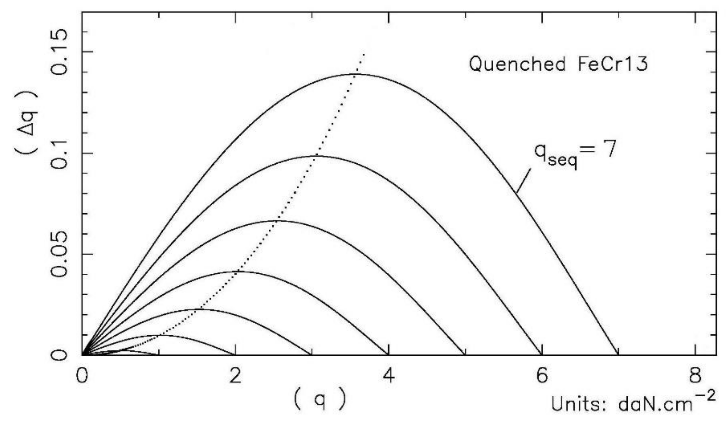
  • Metal choice: We selected VCM substrates in a quenched chromium stainless steel alloy Fe67Cr13, with post-quenched ageing that shows a large elastic deformability, much superior to that of fused silica or glass-ceramics. Deformability is characterized by the ratio of maximum working stress over the Young’s modulus, i.e., the σM.W.S/E ratio.
Other stainless steel chromium alloys exist with a larger elastic deformability than the quenched Fe67Cr13—as selected here. For instance, by including 1–2% molybdenum. Other linear alloys are of interest for VCMs, such as titanium alloy Ti90Al6V4 or beryllium alloy Be95Cu5, but are more brittle. However, for new experiment approaches, minimizing the lathe-machining chip cutting size should be tested for lathe finishing.

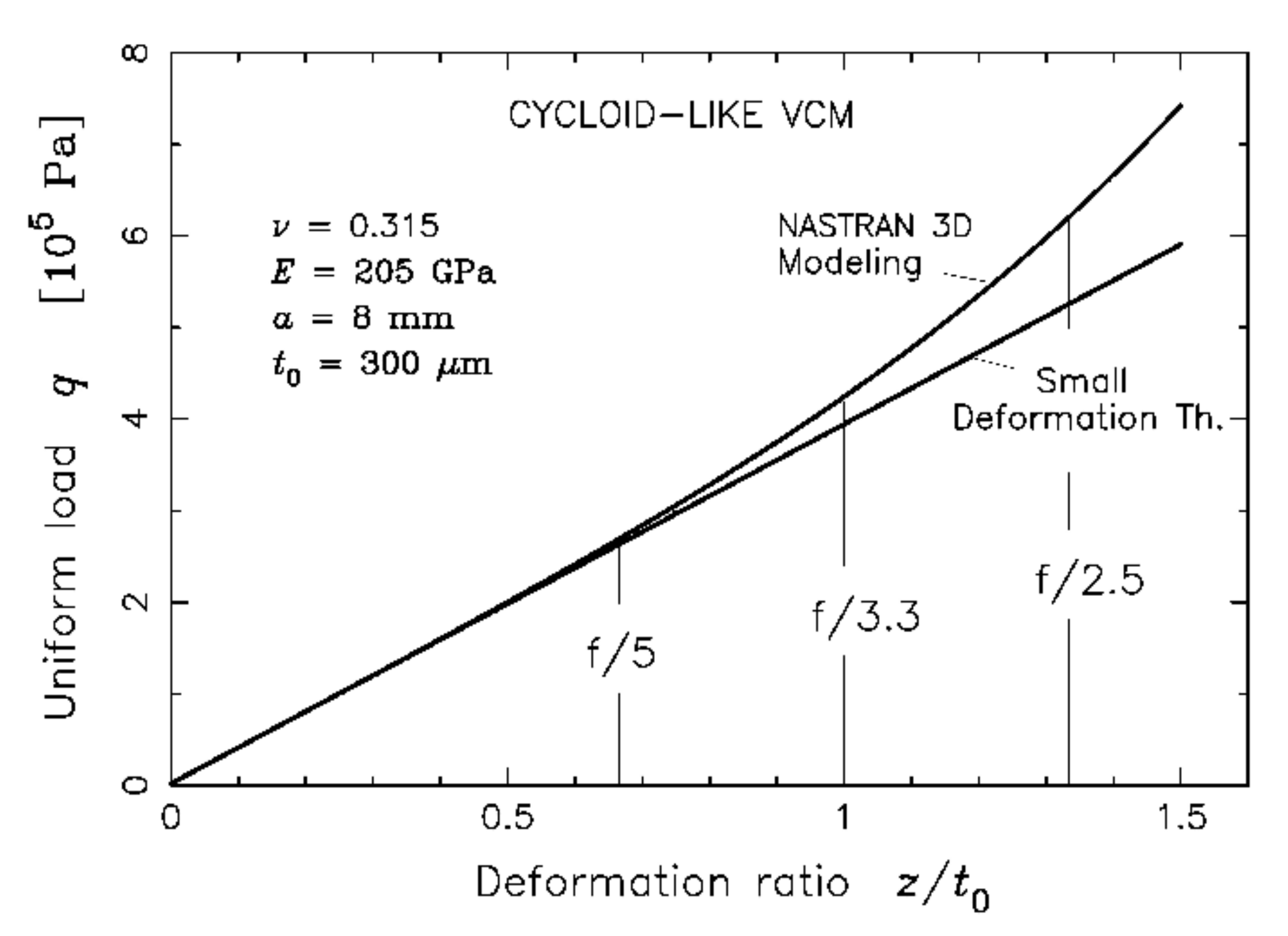
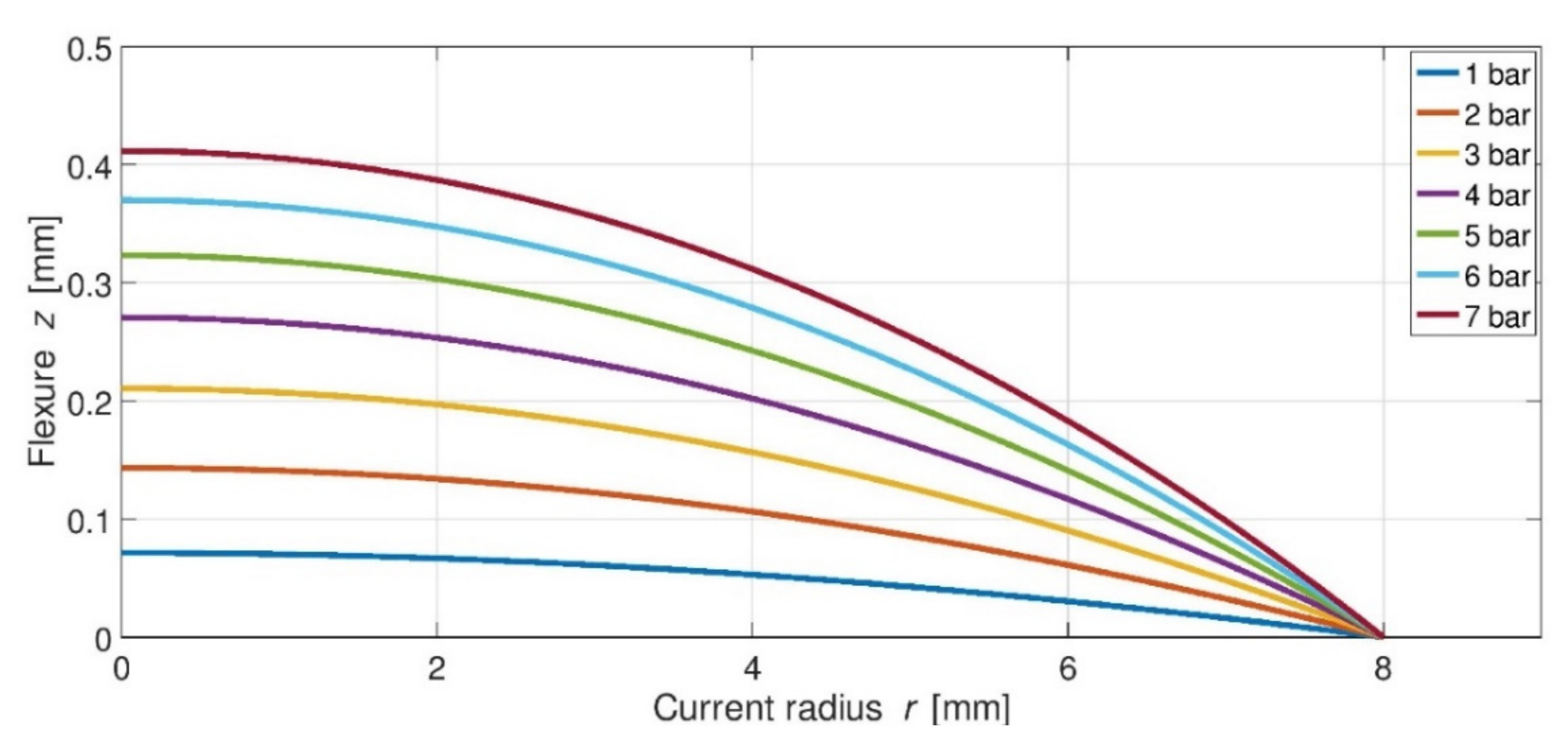
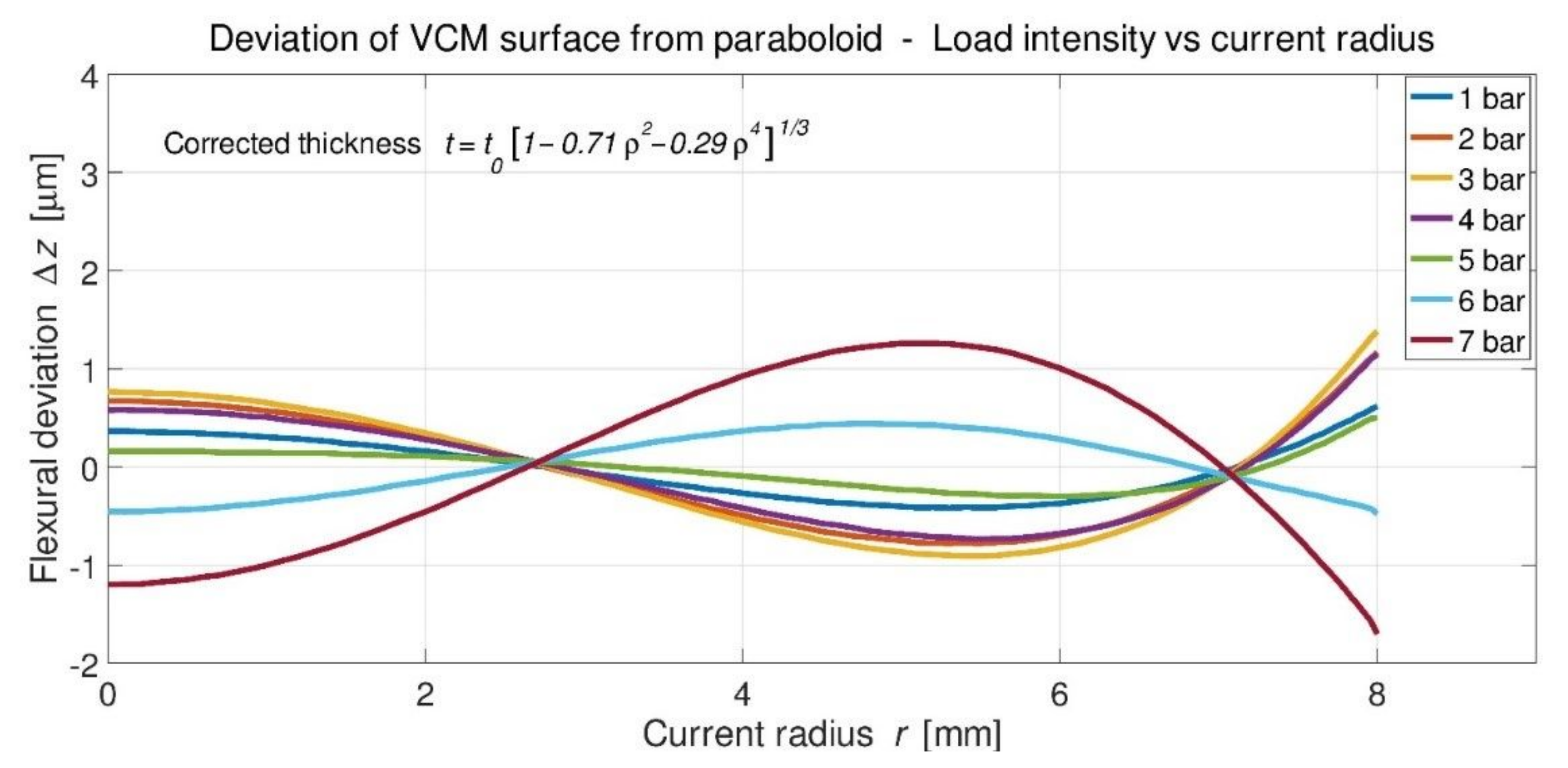
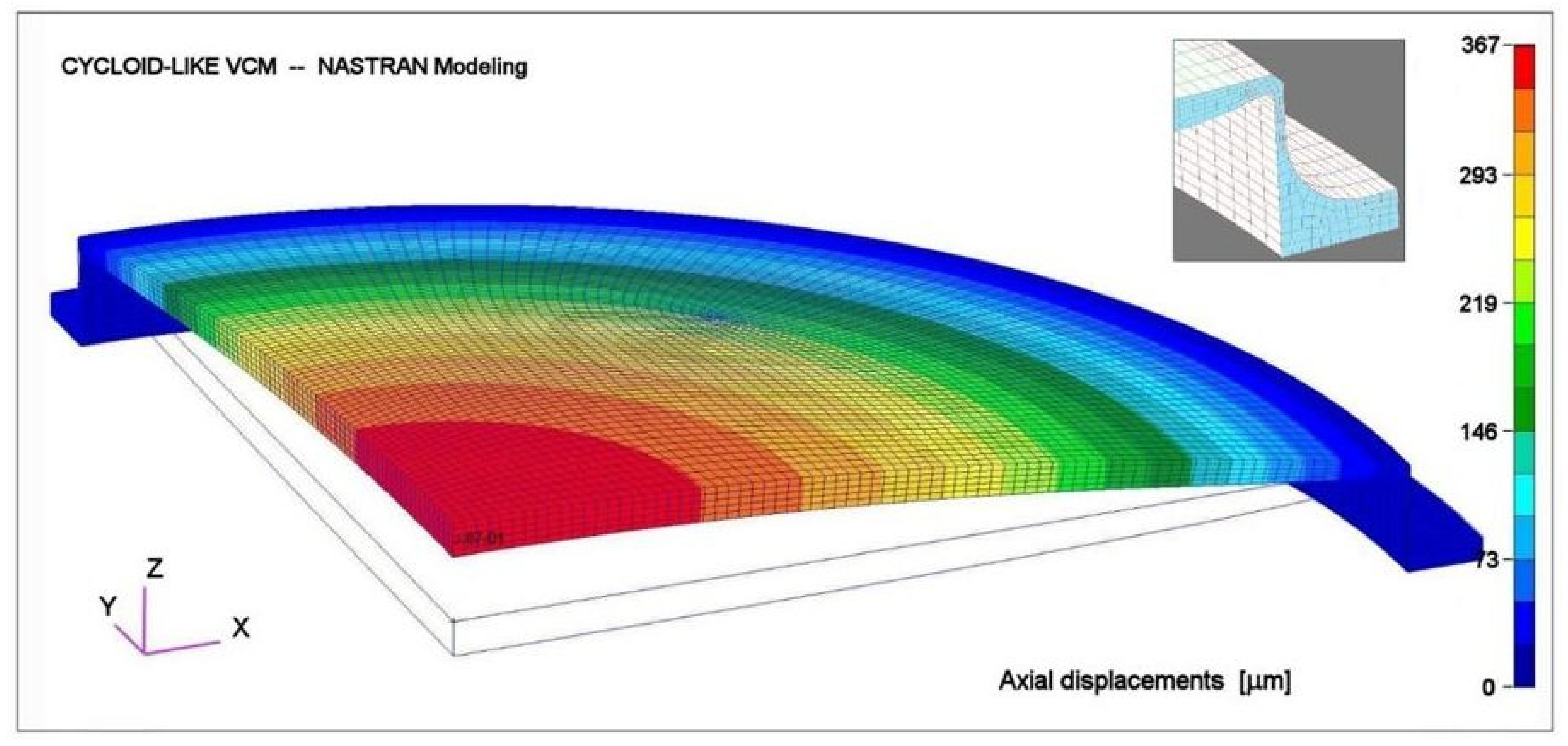
4. Cycloid-like VCM Modeling and Finite Element Analysis

In Section 2, of small deflection theory, flexural results are valid only if flexural sags zmax = a2/2R are small compared to the substrate mean-thickness <t>, i.e., when relationship flexure vs. loading (zmax,q) is linear.
When sags zmax become non-negligible compared to <t>, radial and tangential stresses at the plate middle-surface have to be considered with large deflections of plate’s theory (Timoshenko & Woinosky-Krieger [16]). Investigations with this theory led us to non-linear improved results [2,4]. However, this could not take into account convenient boundaries at the VCM contour.
Vola carries out the present modeling with a finite element analysis (FEA) code. This avoids previous inconveniences encountered with the large deflection theory below, and provides a remarkable calculation accuracy. Modeling of a cycloid-like VCM is investigated for the two following cases: (i) VTD plate alone and, (ii) VTD plate linked in a single piece with an outer rigid ring via a very thin collarette. This uses MSC-Nastran code by MSC-Software with the large displacement option (SOL 106) and takes into account well defined boundaries.

4.1. VCM Modeling of a VTD Plate Alone under Uniform Load

Each finite element’s boundaries provide equilibrium by use of a complete local equation set. FEA analyses was carried out preliminarily with VCM thickness t = t0 (1 − ρ2)1/3, 2a = 16 mm diameter, t0 = 300 µm central thickness, in a quenched stainless steel chromium FeCr13 alloy of high ultimate strength with Young’s modulus E = 205 GPa and Poisson’s ratio ν = 0.315. For uniform loads applied from q = 0 to q = 7 bars, one shows that the deformation is non-linear (Figure 3). Nastran provides the flexure z(r) (Figure 4) and shows the deviation ∆z(r) to a purely parabolic shape (Figure 5).
Boundaries’ conditions for the thickness distribution at edge, ρ = r/a = 1, were defined by setting t(ρ = 1)/t0 = 0.5. Other Nastran conditions at contour are no ending moment and being free to move radially. The origin of displacement is the mirror center. Quarter sections of VCM axial displacements are shown before and after applying an averaged intensity load of q = 5.3 bars (Figure 6).
Instead of thickness t = t0 (1 − ρ2)1/3, and after several attempts, an interesting thickness distribution (with t0 = 300 µm) may take the form t = t0 [1 − βρ2 − (1 β)ρ4]1/3 (Figure 6). Another feature for the VLTI VCMs is that if they are not used all over the full diameter 2a = 16-mm, then Vola proceeds to new optimizations by the least-mean square for apertures of 16 and 14-mm, respectively (Figure 7 and Figure 8).
For a single plate without an outer collarette, the optimal result is t = t0 (1 − 0.69ρ2 − 0.31ρ4)1/3, with a central thickness of t0 = 300 µm, and a mean uniform load of q = 5.3 bars.
Due to a vertical tangent at the VCM’s edge, the outer shape can be modified without altering the accuracy of the Nastran calculations. For all previous meshing models, the outer part of the VCM is set to a conical shape for 0.9 < ρ < 1, with ρ = r/r0 and r0 = 8 mm. The outer conical meshing model entailed a negligible effect compared to the theoretical profile. The obtained distribution shows an over-thickness that is, at maximum, near ρ = 0.85 (Figure 9).
Compared to the small deformation theory, the optimized thickness obtained with the Nastran FEA of a single plate model alone is 18% thicker, near ρ = 0.85.
One considers hereafter the geometrical elements, taking into account link-conditions of a single plate linked through a thin collarette with a rigid outer ring.

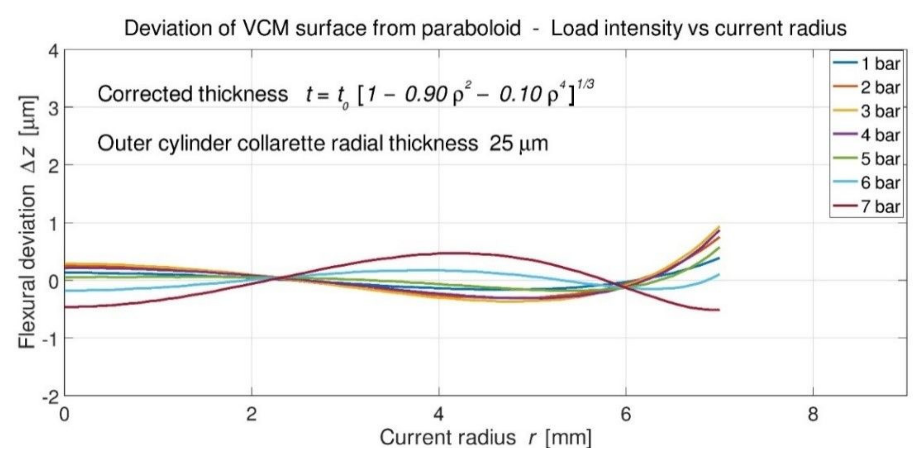
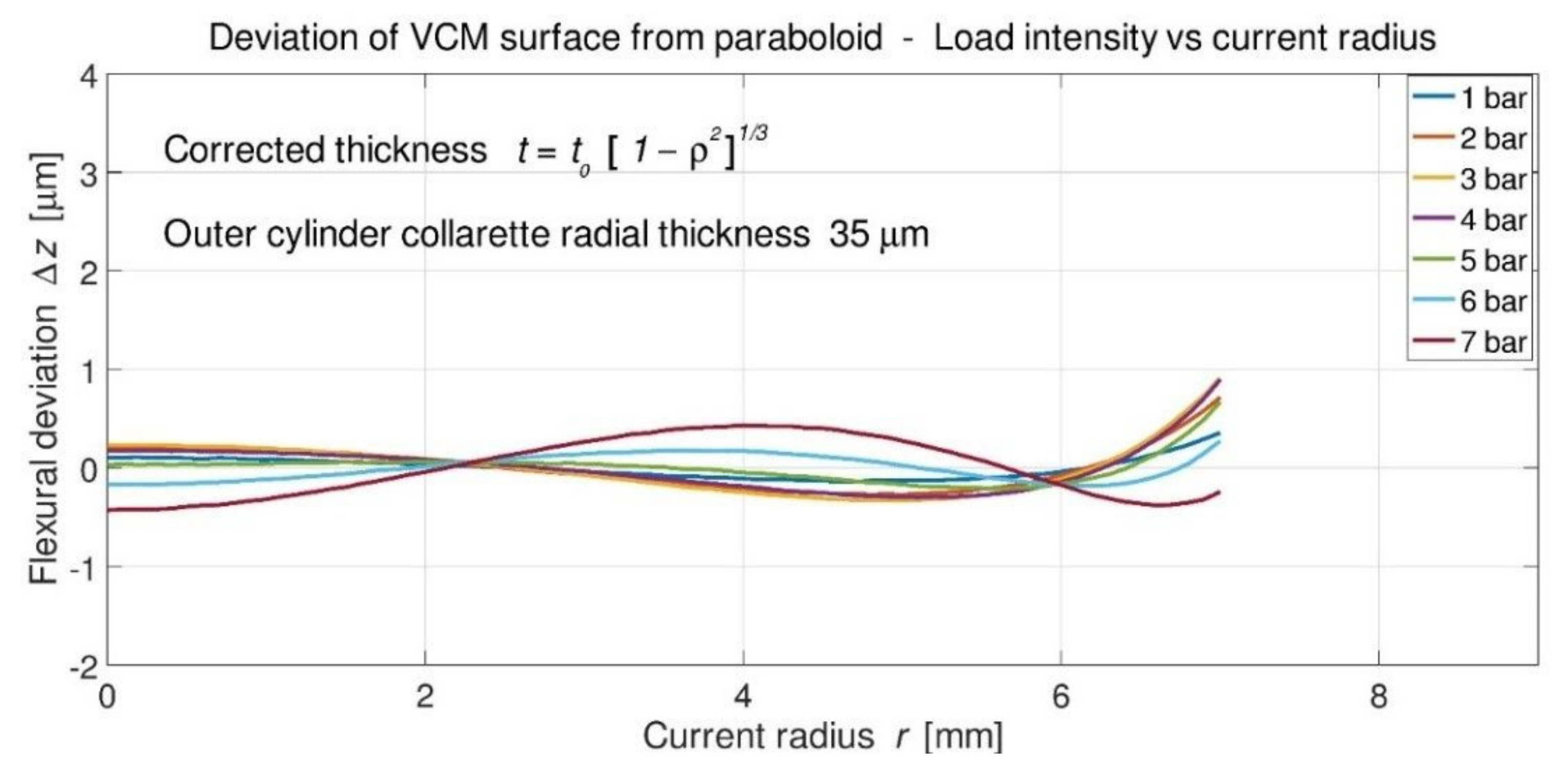
4.2. VCM Modeling Linked to an Outer Cylinder Collarette and Rigid Ring

For practicable reasons of construction of cycloid-like form VCMs, the mechanical design is completed with a radially very thin cylinder collarette linked on one side to the single plate edge and at the other side to a rigid outer ring. This assembly—plate-collarette-ring—is holostérique, i.e., is a one-piece construction.
Nastran modeling is able to accurately perform flexural optimizations of zones which have very different thicknesses. The two boundary conditions at the base of an outer rigid ring are as follows: the base of the ring is free to move radially, and tangential rotation is unmovable. The narrow collarette was set up as at least three-layer meshing (Figure 10).
Compared to the results shown above, with the plate alone, previous results have significantly changed. Surprisingly, optimizations with Nastran show that for radial thicknesses, collarettes of 25 and 35 µm, respectively, one recovers optimal deviations of the theory of a small deformation (Figure 11 and Figure 12).
These results show that, with a 35-µm radial thickness collarette, the best optimization is coincidentally t = t0 (1 − ρ2)1/3, i.e., a thickness which is also found from the elasticity theory of thin plates (cf. Section 2.2) (Figure 13). One may note that, for a 13 mm clear aperture VCM and a load-range in [0, 6-bars], deviations are all included into one He-Ne wavelength (633-nm) PtV maximum deviation.
Results of the final model thickness distribution, TNastran, are identical to that from the thin plate theory except near the edge (Table 1). The VCM is a single-piece (i.e., holostérique) where the mirror edge is linked to a rigid ring via a thin collarette 35-µm radial width. The rigidity-ratio from the mirror edge over the collarette is (119/35)3 ≅ 40, thus providing a high mirror-edge flexibility and convenient geometry (Figure 14).
Uniform loads are limited from 5 to 5.5-bars for VCMs of the ESO-VLTI delay lines (see hereafter); we then have flexural deviations to paraboloids that are smaller than half-wavelength PTV for loads q in a FEA range of [0, 6 bars].

5. Realizations and Results of Cycloid-like VCMs

5.1. Various Developments with VCMs

The first cycloid-like VCM (i.e., Type 1) was invented and developed by Lemaitre in 1974 [1] on the instigation of Connes & Michel [17] at the Laboratoire Aimé-Cotton, CNRS Bellevue-Meudon, for a two-arm Fourier-Transform Infra-Red (FTIR) spectrometer. The VCM thickness variation was made by an electro-erosion technique, over a 20-mm clear aperture in a single piece of stainless steel. This VCM substrate was linked to a very thin cylinder at the edge via a rigid ring. Installed as a field compensator—on a cat’s-eye reflector of one of the two-arms—curvature variation was controlled by air pressure, while the optical path was changed by translation. The VCMs allowed conjugation of the output pupil and thus provided an optimal optical étendue—after P. Jacquinot—i.e., a luminosity gain of about 100.
The next developments of cycloid-like VCMs required the use of a CNC lathe for generating the profile thickness. One of them was built, around 1990, for the Large FTIR spectrometer at LPMA, P. & M. Curie University, Paris-Jussieu. Further developments and constructions of cycloid-like VCMs were performed for the recombination system of the two-telescope-interferometer GI2T-CERGA, and the ESO VLTI array composed of four 8-m unit telescopes (UT) and four 1.8-m auxiliary telescopes (AT) (Figure 15 and Figure 16).
The ESO VLTI is the largest interferometer for angular high resolution in astronomy. With fixed base lines of the four UTs and the variable positioning of the x–y base lines of the four ATs, the recombination tunnel allows the translation of the eight delay lines over 130-m length. Present beam-combiner instruments, dedicated to various near and mid-infrared bands, are PIONIER (H-band), GRAVITY (K-band) and MATISSE (L- and N-band).
Eight cat’s-eye systems are movable parts of the eight delay-line recombination tunnel of UTs and ATs. These cat’s-eyes are retroreflective three-mirror systems by F. Dérie [13], composed of a two-mirror Ritchey–Chrétien and a VCM as third mirror. Each of the height VCMs reimages a focus of the VLTI array primary mirrors.
Eight VCMs are also dedicated to pupil conjugation of the ATs to delay lines because (i) each AT can change location in the ESO concept of a movable x–y positioning baseline and, (ii) each AT imaging observation is made for the object to be studied and another object as a reference star. This requires a VCM-pair installed at each AT output to recombine the pupil at the input of each delay line. The maximum baseline size is 130-m, allowing few milli-arcsec resolutions. A change in the x–y configuration is incremental and then implies a discrete curvature setting of each VCM-pair.
After some prototyping experiments at Marseille Observatory, and later at LAM, in the period 1990–1998. Twenty cycloid-like VCMs were realized in our institute for the VLTI from 1998 to 2018, including four spares. Ten new spare VCMs are under construction in 2019–2024 at LAM, as an ESO-AMU approved contract, for which the present modeling should provide diffraction-limited extended-FOVs.

5.2. VCM Material and Construction Process

The material for VCM lathe machining is a long round bar in martensitic stainless chromium steel Fe87Cr13, quenched at 950 °C and post-quench aged between 350 and 400 °C. This alloy is made by the Ugitech Company, Ugine, France, designed as X30C13 and Ugitech grade UGINA 4028W [18]. This alloy is mainly used for aircraft construction because of its fine grain texture and high mechanical properties. Other equivalent names of this alloy are Z30C13 in the European standard or AISI420 in the American standard, without any specification of the quenching treatment.
After CNC lathe machining and polishing, the VCM substrates are flat or quasi-flat at rest, and become actively convex up to 5.3-bars of air-pressure, typically for the full VLTI zoom range. However, few of them have a VLTI zoom range of up to 6-bars.
Summarizing the theoretical results of the cycloid-like VCM opto-elasticity design from Nastran:
Poisson ratioν = 0.315Young modulusE = 205 GPa
Central thicknesst0 = 300 µmCollarette radial thick.r = 30 μm
Optimized loadq = 5.3 daN·cm−2Collarette stressσmax = 1100 MPa
Optimized flex.-sag z0 = 298 µmRadius of CurvatureR = 107.4 mm
Outer diameter2a = 16 mmZoom f-ratiof/∞–f/3.35
Clear aperturedOpt = 13 mmZoom f-ratiof/∞–f/4.14
Maximum loadq = 6.0 daN·cm−2Max. zoom range for dOptf/∞–f/3.57
Each cat’s-eye VCM mount is a light weighted assembly (Figure 17). The curvature control maintains the cophasing of the field-of-view whilst the delay line translation maintains the cophasing of the optical path. The VCM assembly is supported by three piezoelectric device ensuring angular remote-control correction errors during translation along delay lines. Developed by Mazzanti at the instigation of Dérie, the air pressure actuation system is an air box installed near the translation carriage of the VCM’s cat’s-eye system. Air capacity is remotely filled up each day at the zeroing position. During observations, remote control pressure, with respect to the assigned translation positioning, used electronic valves.
Many stages are necessary to obtain a polished, fully operating VCM. These operations also require equipment, as follows:
(i) An air-pressure generator system, two accurate gauges, a safety valve, and control software. (ii) A He-Ne Fizeau interferometer. (iii) A wheel of various power positive lenses, used as collimator lenses, for optical null-test with caliber radius of curvature R2800, R420, R230, R140 and R105-mm. (iv) Cast-iron tool-pairs of 0, 2, 4, 6, 8, 10, 12-µm sags over a 13-mm aperture diameter for surfacing the VCM shape. (v) A special loading device for the plasticity reshaping of convexity that reverses air pressure applied to VCM substrate—usable up to a 8-bars maximum load if needed.
Summarizing the main stages of the construction process for VCMs of VLTI:
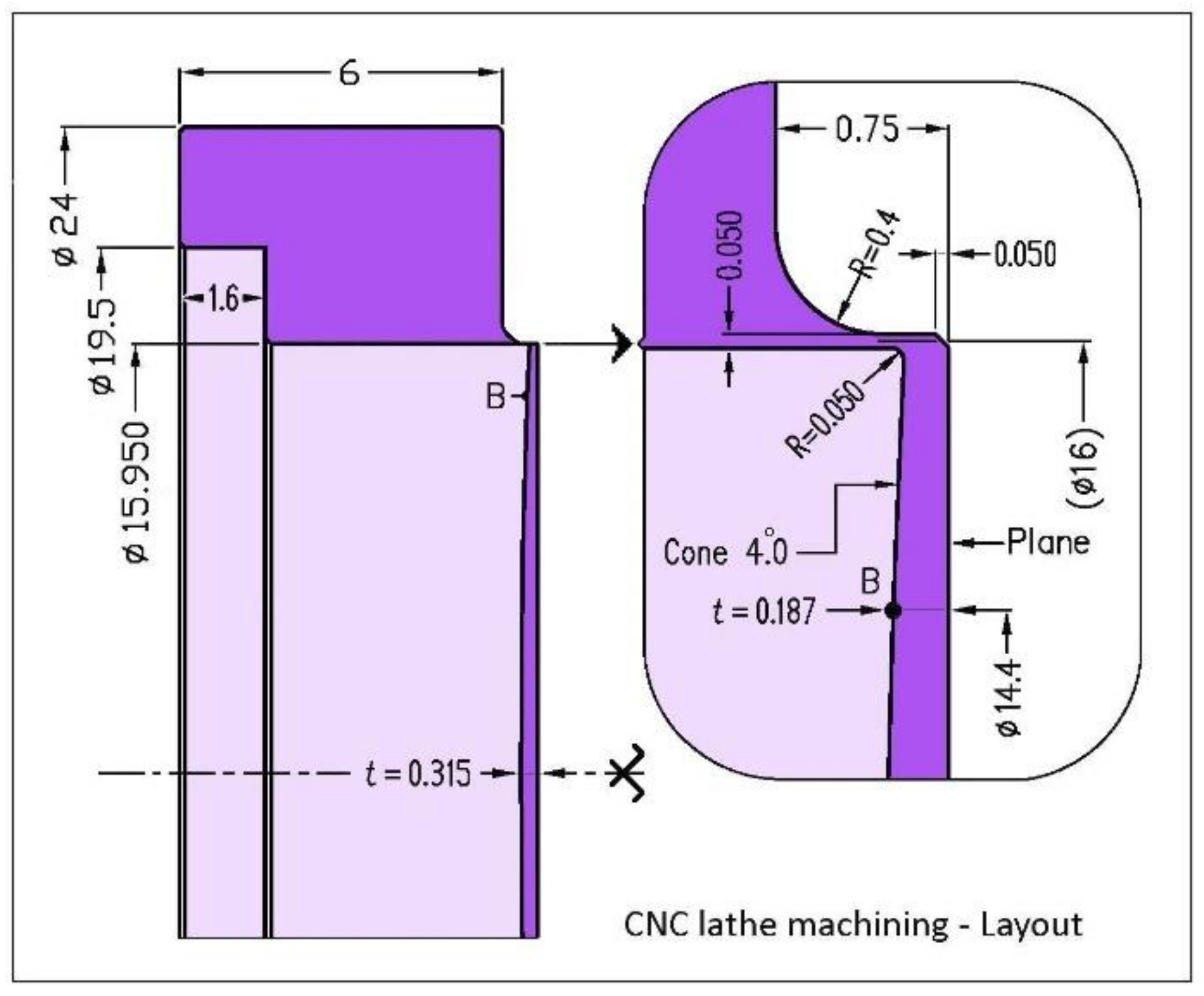
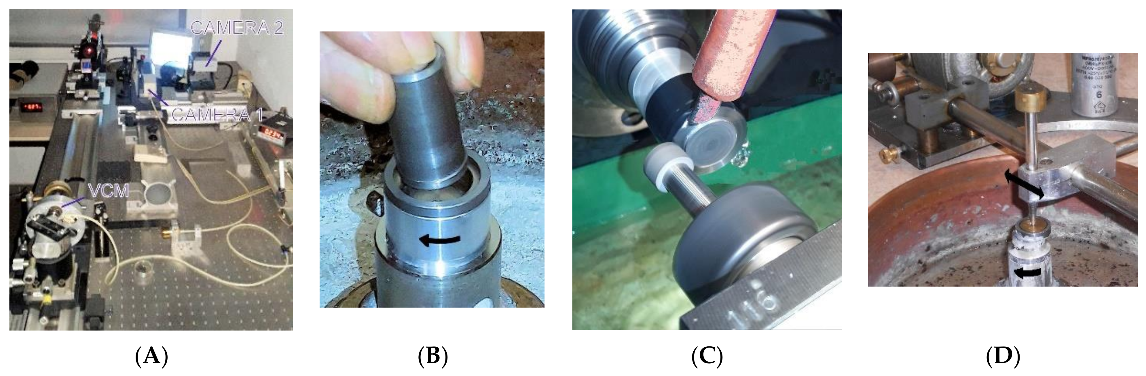
  • Multi-function CNC machining with Hardinge lathe and polycrystalline cubic boron nitride (CBN) cutting tools [19]. A constant axial over-thickness is added for the machining, tCNC = 15 + t0 = 315-µm (Figure 18), giving room for the next grinding and polishing. The outer collarette radial thickness is machined slightly thicker, at ∆r = 50-µm. CNC positioning control accuracy is better than 1-µm (sub-contracted by Gauthier Precision SAS). However, the minimum chip thickness for a quenched chromium steel is close to, say, 10-μm. There exists a minimum chip cut thickness, below which no chip can be formed stably, as shown in Matsumura [20].
  • Front surface grinding, 3-µm diamond grain, with, preferably, a flat cast-iron tool—or a concave tool with up to 10-µm sag—ensuring the minimum curvature matter removal from the previous lathe surface. Fizeau checking at caliber R2800.
  • Rear face edge grinding, 3-µm diamond grain, with an appropriate conical form in cast iron. The VCM, rear side up, rotating slowly, and the conical form rotating from slow to increasing speed.
  • Outer edge collarette rectification of VCM mounted on lab lathe with a flexible clamp rotating slowly—centering better than 0.2-µm accuracy. Machining at a 10° inclination, with a small external grinding wheel in cubic boron nitride (CBN) at 18,000-rpm. The collarette radial thickness becomes ∆r ≅ 30 to 35-µm.
  • Repeat stage 2 of front surface grinding. Use an optimal concave tool among 0, 2, 4, 6, 8, 10, 12-µm sags for minimum removal matter. Fringe Fizeau checking at caliber R2800.
  • Pre-stressing at the maximal load between 5 and 5.5-bars to slightly overpass R105 Fizeau test. This generates a convexity of 9-µm sag, typically, over a 14-mm diameter in the Fizeau test R2800. This convexity is due to the collarette high stress which also generates an axial displacement of ~8-µm, typically, i.e. its axial elongation. Pre-stressing provides elasticity linearization of the stress–strain relation at the collerette level (see Section 5.3).
  • Repeat grinding of stage 5 of the front surface grinding. Use the optimal concave tool for minimum removal matter. Fizeau checking at R2800. N.B.: If the VCM convexity overpasses 17-µm sag, then one operates directly to stage 8 of the operation.
  • Inverse stressing if necessary. The curvature of caliber R2800, with respect to a plane surface, corresponds to a sag of 8.7-µm. If the convexity is in the range sag 17-22-µmand since the collerette plastic effect is due to dominant stresses in the pre-stressing operation between 5 and 5.5-bars—, then one requires a special loading device. This device can generate an air pressure loading at the VCM’s opposite side, by successive trials up to 8-bars as a maximum. After this operation, one makes the pre-stressing again, as in stage 6, for reshaping. Repeat this operation up to obtaining a curvature of 17-µm sag at R2800 Fizeau checking. A cycle inverse stressing and pre-stressing is able to reduce convexity up to a 5-µm sag amount without removing material. If this result is not achieved, the VCM’s substrate is discarded.
  • Polishing with a pitch tool rotating below, by Lanzoni. The VCM translates up the tool. Alumina abrasive Al2O3, grain size 1-µm for 8–12 h, 0.3-µm for 8–12 h, and 0.05-µm for 1 h. Polishing pressure is 30-g.cm−2. The polishing cinematic parameters generate either concavity or maintain a stable curvature. Then, starting from a VCM convexity smaller than 17-µm sag, a slightly convex 6-µm sag shape is achieved at the end of polishing. Fizeau checking at R2800.
  • He-Ne interferogram data acquisitioned by Lanzoni with the Fizeau test with calibers from R2800 to R105.
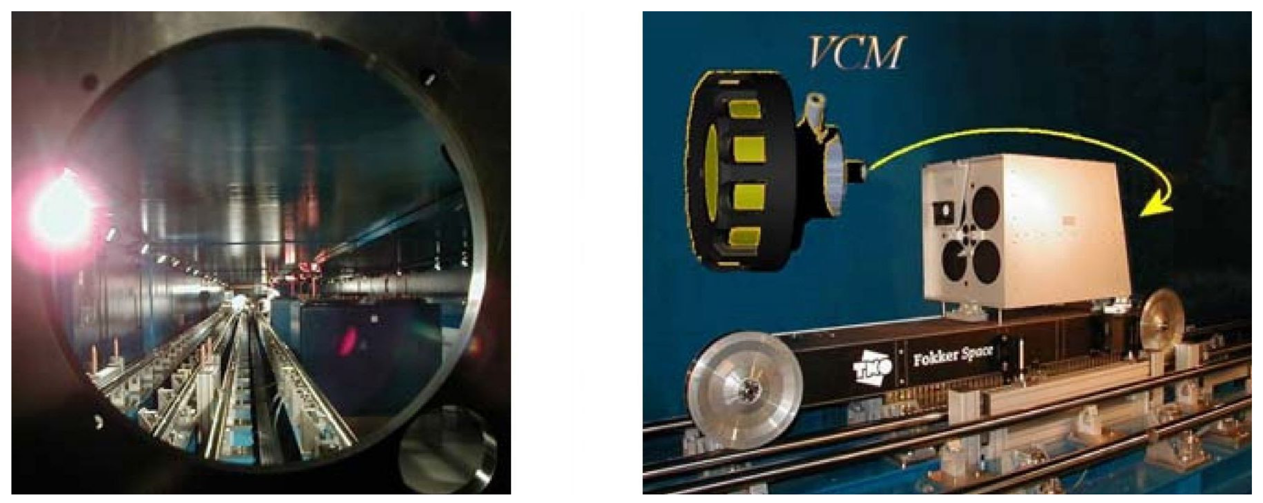
  • Gold coating in the vacuum chamber for near-infrared and infrared by ESO.
Although operation-1 above was conveniently realized, tentative of industrialization for the rest up to operation-10 were found unsuccessful, and then were carried out at LAM. The VCM substrates were executed with CNC lathe at the thicknesses t*(r), that includes a constant over-thickness of r < 8-mm. The substrates were linked to the rigid outer ring via a thin collarette at the edge in a one-piece design (Table 2) (Figure 18).
Photos of main operations for the VCM elaboration, such as the Fizeau optical test interferometer, the inner edge retouch for improving geometry by the finishing grinding conical tool, the collarette outer rectification with a boron nitride grinding wheel, and the polishing system, are displayed by Figure 19.

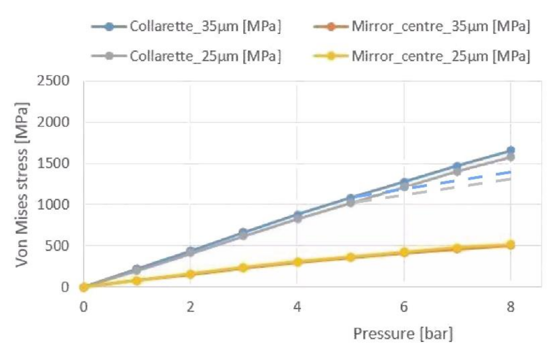
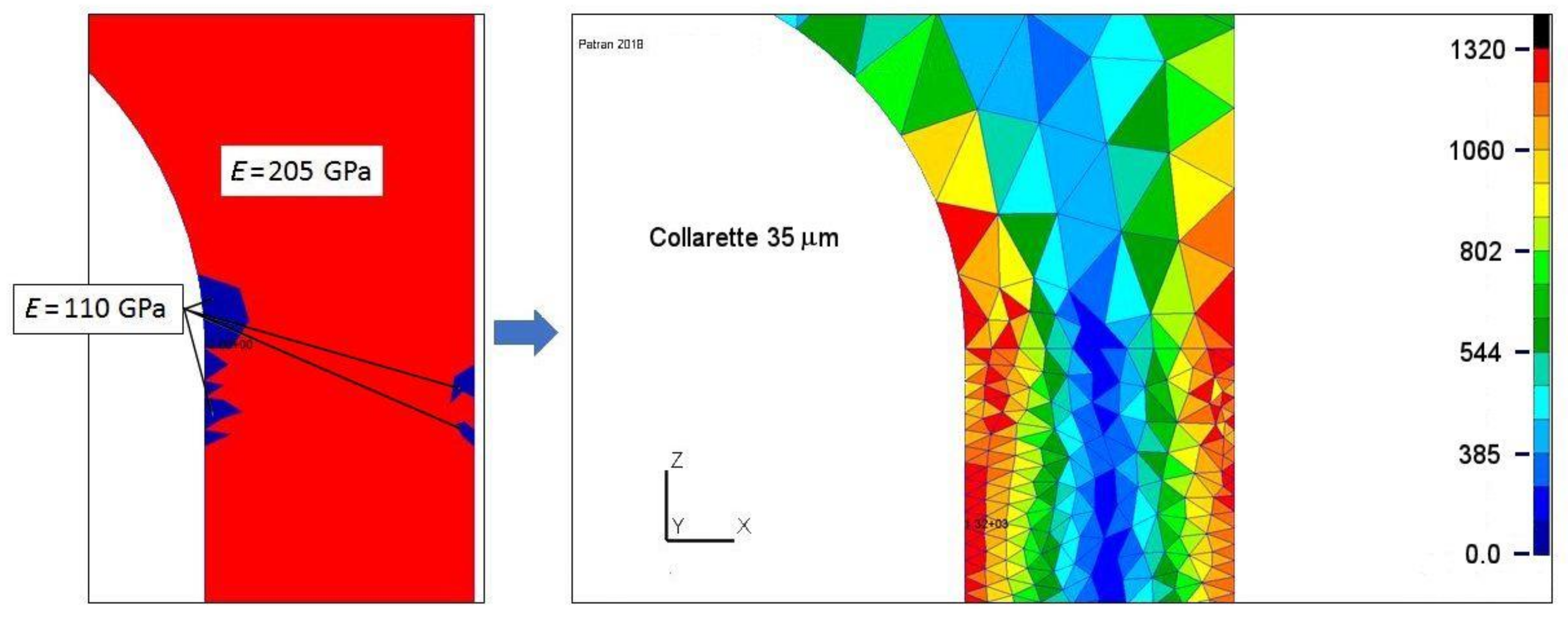
5.3. Pre-Stressing and Maximum Stresses

The stainless steel chromium alloy, Fe87Cr13, i.e., X30C13 or AISI420, shows a high ultimate stress when quenched at 750 °C and followed by tempered heating between 250 and 400 °C (effect known as post-quench ageing of the martensitic transformation). This alloy allows the linearization of the stress–strain relationship (Hooke’s low). Ultimate stress σUlt is near 1700-MPa, typically. Yield stress of 2% elongation σY.S is near 1500-MPa, as given by Aubert & Duval [21], which linearly corresponds to the Rockwell hardness HRC = 45.
All VCMs are machined into substrates from a quenched round bar post-quench ageing. Then substrates are pre-stressed at σP.S below 1400-MPa and, during zoom range, the maximum working stress σM.W.S must remain below 1245-MPa, corresponding to 6-bars of air pressure, R = 92.8-mm and f/2.90 at 2a = 16-mm diameter (Figure 20 Left). Hysteresis appears whatever the zoom range domain (Figure 20 Right). The amplitude of this effect was determined and modeled at the lab as a function of each maximum load in a cycle (cf. Section 5.6 hereafter).
For a cycloid-like VCM of the above final optimized design, and large loads up to 8-bars, ola obtains with Nastran: (i) sag vs. air pressure, and (ii) Von Mises stresses vs. air pressure, thus for each collarette the radial thicknesses are ∆r = 35 and 25-µm, respectively (Figure 21 and Figure 22).
Nastran maximal Von Mises stresses are located at the collarette inner and outer surfaces (Figure 22). Taking into account the pre-stressing operation applied to each VCM—that performs Hooke’s law linearization while generating a creeping effect—a special classical process for Nastran optimization is to model the creeping effect as follows (ola):
For a radial thickness collarette of 35-µm, and the hypothetic case of 8-bar pressure (not often used in practice and that would lead to 1640-MPa Von Mises maximum stress), the creeping effect—i.e., plasticification—is taken into account by introducing some zonal change of Young’s modulus. For those areas one selects, E = 110 GPa, instead of E = 205 GPa, and then obtains a maximum Nastran stress of 1320 MPa (instead of 1640 MPa) (Figure 23).

5.4. Deformability Advantage of Present Alloy over Some Other Materials

From the maximum working strength of quenched chromium stainless steel, Fe87Cr13, σM.W.S = 1245-MPa, and Young’s modulus E = 205 GPa, the metal cycloid-like VCMs show the large elastic deformability. For instance, compared to Heraeus fused silica or glass Schott Zerodur vitro-ceramic, the gain in the elastic deformability ratio—i.e., maximum working stress over Young’s modulus σM.W.S/E—is widely in favor of the Fe87Cr13 alloy by a factor close to 20 ([4] Table p. 272).

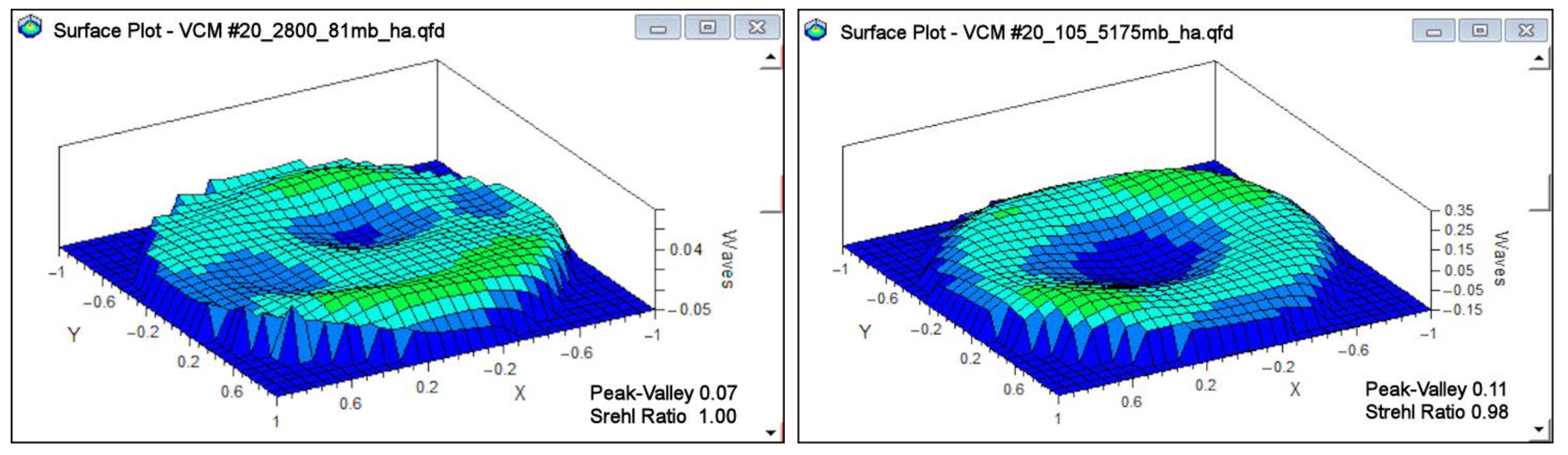
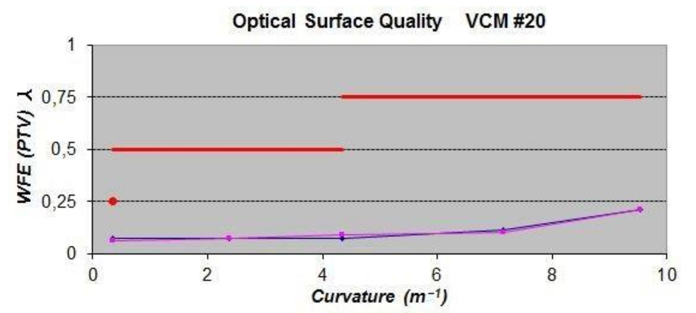
5.5. Interferometric Results

He-Ne interferograms are obtained from our LAM Fizeau interferometer after reduction by Lanzoni with Quick Fringes—a Canadian code [22]—for various curvatures of VCM #20 over a 6-mm clear aperture diameter (Figure 24). ESO-AMU contracts for VCM optical quality is specified in a PTV wavefront-error diagram. The diagram shows the PTV wavefront-error specifications and obtained results for five discrete curvatures, C = 1/R over a 6-mm clear aperture for the VLTI, i.e., a 3″ diffraction-limited FOV.
Two surface-plots show the optical quality of VCM #20 (Figure 25). The maximum PTV error is smaller than the λ/4 He-Ne fringe all over the zoom range (Figure 26). In this latter figure, the red point underlines the ESO specification to achieve a PTV error smaller than the λ/4 He-Ne fringe for an end-polish VCM Fizeau-test with the caliber R2800. The double line –blue and pink– from the experiment test displays an increasing and decreasing pressure cycle.

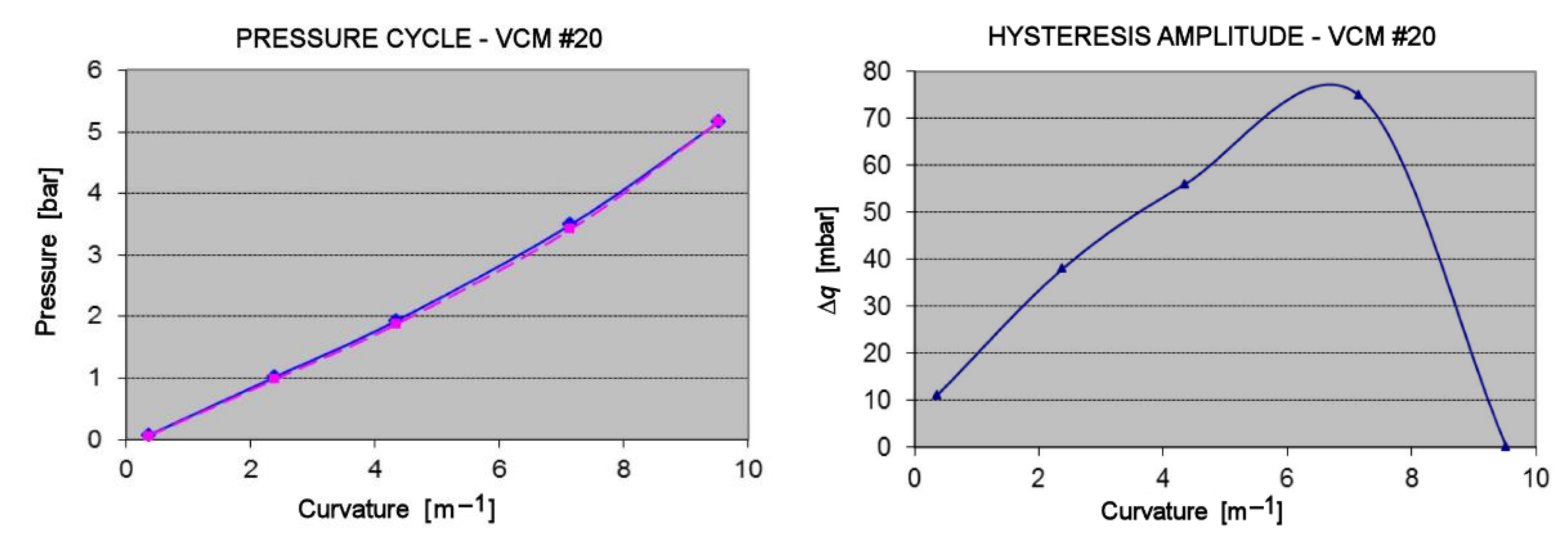
5.6. Hysteresis Cycles and Hysteresis Modeling

Flexural hysteresis of the Fe87Cr13 metal displays a slight decrease of the load-value when the VCM comes back to lower pressures for recovering a given previous curvature. An example of a hysteresis loop is the path AIWJA (Figure 20 Right) where the extremal point W is close to the maximum working stress.
For a loading sequence up to qSeq, and during de-loading back at load q, the same curvature is obtained for a load slightly lower, q–Δq. These data were registered with the Fizeau interferometer—at curvature radii R 2800, 420, 230, 140, 105, 86-mm—during several cycles of load sequence, qSeq. The hysteresis effect may be represented analytically as an odd series [4,23]
q = δ1 q + δ3 q3 + δ5 q5 with q < qSeq,
where δi are coefficients.
The above law on flexural hysteresis states that:
  • During the de-loading, the same curvatures than when loading are obtained by lower applied loads.
  • After the loading and subsequent de-loading sequence of about 12 h, the initial and final curvatures are identical in a new cycle.
From experiment results, one builds a network of theoretical hysteresis curves for various cycle sequences, qSeq, that allow modeling of the typical effects. Each cycle ∆q(q, qSeq)—used for active optics corrections—corresponds to a de-loading time of about five minutes, typically (Figure 27).
Results from stressing cycles of various VCMs up to an air pressure of 7-daN·cm−2—i.e., at 7-bar—allowed us to elaborate the above hysteresis model. For VCMs contractually accepted by ESO, each report includes, especially, data of the pressure vs. the curvature cycle. For instance, VCM #20 was stressed up to q = 5.17-bar at a maximum curvature of (1/105)-mm−1 which provided a null deviation wave at the caliber radius R105 in the Fizeau interferometer. Experiment results of our ESO report, by Lanzoni, include the pressure vs. the curvature and the deduced hysteresis cycle of VCM #20 (Figure 28).
At the Paranal VLTI array site, the curvature control model is completed with the above hysteresis compensation model ( Mazzanti). The final VCM curvature closed-loop system acts at the same level as that of the positioning control of the cat’s-eye translation and tilt.

6. Conclusions

This paper investigates accurate modeling for the elasticity design of cycloid-like VCMs in active optics methods. FEA optimizations allowed us to improve the preliminarily design elaborated from analytic small deflection theory. FEA shows that the diffraction criterion can be achieved for a large zoom range compensation over an angular VLTI field-of-view larger than required. Beam recombination of the VLTI array is efficiently achieved by both the curvature-control and hysteresis modeling-control of the in situ VCMs.
However, it is pure coincidence that Nastran thickness modeling with the collarette leads us to an identical thickness to that of small deflection theory without any collarette, i.e., t = t0 (1 − ρ2)1/3.
Regarding mechanics’ and optics’ fabrication, this includes mainly: NC lathe micro-cutting with a minimum chip thickness, optical surface grinding, inner edge grinding, outer collarette rectification, pre-stressing for elastic linearization, final grinding and polishing. Besides all current interferometric tests, this technology process shows some complexity.
Since the first cycloid-like VCMs built as prototypes at the Marseille Observatory in 1975, ensuing developments at LAM, since 1998 for the ESO Paranal VLT Interferometer Array, provided diffraction-limited mandatory specifications of 3″ FOV for a 6-mm clear aperture. With our ESO-AMU approved convention of making 10 VCM spares up to 2024, the performance can be improved from the results of present modeling by providing diffraction-limited extended-FOVs.

Author Contributions

Conceptualization, G.R.L. and P.V.; methodology, G.R.L. and P.V; software, P.V. and P.L.; validation, all authors; formal analysis, P.V. and P.L.; investigation, G.R.L.; resources, LAM laboratory; data curation, P.V. and P.L.; writing—original draft preparation, G.R.L.; writing—review and editing, G.R.L.; visualization, G.R.L.; supervision, G.R.L.; project administration, G.R.L.; funding acquisition, F.J.D. and F.Y.G. All authors have read and agreed to the published version of the manuscript.

Funding

This research was funded by a contract-convention ESO-AMU at the request of PG of ESO. The AMU reference is PO087610/MRIE.

Conflicts of Interest

The authors declare no conflict of interest.

References

  1. Lemaitre, G.R. Elasticité et Miroirs à Focale Variable. Comptes Rendus De L’Académie Sci. 1976, 282, 87. [Google Scholar]
  2. Ferrari, M.; Lemaitre, G.R. Analysis of large deflection zoom mirrors for the ESO VLTI. Astron. Astrophys. 1993, 274, 12–18. [Google Scholar]
  3. Ferrari, M. Development of variable curvature mirrors for the delay lines of the VLTI. Astron. Astrophys. Suppl. Ser. 1998, 128, 221–227. [Google Scholar] [CrossRef] [Green Version]
  4. Lemaitre, G.R. Elasticity Theory and Astronomical Optics—Active Optics Methods; Springer: Berlin/Heidelberg, Germany, 2009; ISBN 978-3-540-68905-8. [Google Scholar]
  5. Connes, P. Astronomical Fourier spectroscopy. Annu. Rev. Astron. Astrophys. 1970, 8, 209–230. [Google Scholar] [CrossRef]
  6. Camy-Peyret, C.; Payan, S.; Jeseck, P.; Té, Y. Mesures spectroscopiques de constituents. Comptes Rendus De L’académie Sci. Ser. IV-Phys. 2001, 2, 905–922. [Google Scholar]
  7. Labeyrie, A. Stellar interferometry methods. Ann. Rev. Astron. Astrophys. 1978, 16, 77–102. [Google Scholar] [CrossRef]
  8. Mourard, D.; Bonneau, D.; Glentzlin, A.; Merlin, G.; Petrov, R.G.; Pierron, M.; Thureau, N.D.; Abe, L.; Berio, P.; Blazit, A. The GI2T/REGAIN interferometer, in Astronomical Interferometry. In Proceedings of the Astronomical Telescopes and Instrumentation, Munich, Germany, 27 March–1 April 2000. [Google Scholar] [CrossRef]
  9. Beckers, J.M. Field of view considerations for telescope arrays. In Proceedings of the 1986 Astronomy Conferences, Tucson, AZ, USA, 1–2 March 1986. [Google Scholar]
  10. Beckers, J.M. Interferometric imaging with the VLTI. J. Opt. 1991, 22, 73. [Google Scholar] [CrossRef]
  11. von der Luehe, O.; Derie, F.; Koehler, B.; Leveque, S.A.; Paresce, F.; Verola, M. Interferometry with the ESO very large telescope. In Optical Telescopes of Today and Tomorrow; International Society for Optics and Photonics: Landskrona/Hven, Sweden, 1997; Volume 2871, pp. 498–503. [Google Scholar] [CrossRef]
  12. Glindemann, A.; Abuter, R.; Carbognani, F.; Delplancke, F.; Derie, F.; Gennai, A.; Gitton, P.B.; Kervella, P.; Koehler, B.; Leveque, S.A. The VLT Interferometer: A unique instrument for high-resolution astronomy. In Interferometry in Optical Astronomy; International Society for Optics and Photonics: Munich, Germany, 2000; Volume 4006, pp. 2–12. [Google Scholar] [CrossRef]
  13. Dérie, F.J. VLTI delay lines: Design, development and performance requirements. In Interferometry in Optical Astronomy; International Society for Optics and Photonics: Munich, Germany, 2000; pp. 25–30. [Google Scholar] [CrossRef]
  14. Koehler, B.; Leveque, S.A.; Gitton, P.B. A decade of VLTI technical development. In Interferometry for Optical Astronomy II; International Society for Optics and Photonics: Waikoloa, HI, USA, 2003; Volume 4838. [Google Scholar] [CrossRef]
  15. Gonté, F.Y.J.; Alonso, J.; Aller-Carpentier, E.; Andolfato, L.; Berger, J.P.; Cortes, A.; Delplancke-Strobele, F.; Donaldson, R.; Dorn, R.J.; Dupuy, C. NAOMI: A low-order adaptive optics system for the VLT Interferometer. In Optical and Infrared Interferometry and Imaging V; International Society for Optics and Photonics: Edinburgh, UK, 2016; p. 990720. [Google Scholar] [CrossRef]
  16. Timoshenko, S.P.; Woinowsky-Krieger, S. Theory of Plates and Shells; McGraw-Hill Publ. Company: New York, NY, USA, 1964; p. 396. ISBN1 10:0070858209. ISBN2 13:9780070858206. [Google Scholar]
  17. Connes, P.; Michel, G. Astronomical Fourier spectrometer. Appl. Opt 1974, 14, 2067–2084. [Google Scholar] [CrossRef] [PubMed]
  18. Ugitech Corp. UGIMA 4028W. 1990. Available online: https://eservices.ugitech.com/CatalogDocuments/BarProducts.pdf (accessed on 18 January 2022).
  19. Klimenko, S.A.; Mukovoz, Y.A.; Lyashko, V.A.; Vashchenko, A.N.; Ogorodnik, V.V. On the wear mechanism of cubic boron nitride base cutting tools. Wear 1992, 157, 1–7. [Google Scholar] [CrossRef]
  20. Matsumura, T. Chip formation and minimum chip thickness. In Comprehensive Materials Processing; Elsevier Ltd.: Amsterdam, The Netherlands, 2014; Section 11.07.4.1; ISBN 978-0-08-096533-8. [Google Scholar]
  21. Aubert & Duval Corp. Strength of Quenched Chromium Stainless Steel. 2000. Available online: https://www.aubertduval.com/wp-media/uploads/sites/2/pdf/fr_X13.pdf (accessed on 18 January 2022).
  22. Quick Fringes Code by Diffraction Limited Corp. Ottawa, Canada. Available online: https://diffractionlimited.com (accessed on 18 January 2022).
  23. Lemaitre, G.R.; Ferrari, M.; Mazzanti, S.P.; Lanzoni, P.; Joulie, P.; Leduc, D.; Copede, M. VLTI pupil transfer: Variable curvature mirrors II—Plasticity, hysteresis, and curvature control. In Interferometry in Optical Astronomy; International Society for Optics and Photonics: Munich, Germany, 2000; pp. 192–197. [Google Scholar] [CrossRef]
Figure 1. Design of Variable Curvature Mirrors derived from the CTD class. (Up): The basic solution requires a uniform bending moment applied along the perimeter. (Down): Axial ring-forces on a vase form providing equivalent bending moments.
Photonics 09 00066 g001
Figure 2. Variable Curvature Mirrors derived from the VTD class. Dimensionless thicknesses T20 with ρ = r/a, ρ [0, 1] are as follows (Lemaitre [4]). (Up-left) Uniform loading and reaction at the edge, T20 = (1 − ρ2)1/3; (Up-right) Axial force at the center and edge reaction, T20 = (ln ρ2)1/3; (Down) Uniform loading and the central reaction, T20 = (ρ2 − ln ρ2 − 1)1/3.
Photonics 09 00066 g002
Figure 3. Load vs. flexure non-linearity for cycloid-like VCM with t = t0 (1 − ρ2)1/3.
Photonics 09 00066 g003
Figure 4. Flexure vs. current radius for cycloid-like VCM with t = t0 (1 − ρ2)1/3.
Photonics 09 00066 g004
Figure 5. Flexural deviation to paraboloid with respect to load intensity with t = t0 (1 − ρ2)1/3.
Photonics 09 00066 g005
Figure 6. Axial displacements for medium intensity load of q = 5.3 bars with t = t0 (1 − ρ2)1/3.
Photonics 09 00066 g006
Figure 7. Optimized thickness distribution t = t0 [1 − βρ2 − (1 − β)ρ4]1/3 over entire radius.
Photonics 09 00066 g007
Figure 8. Deviations for optimized thickness t = t0 (1 − 0.69ρ2 − 0.31ρ4)1/3 over radius r = 7 mm.
Photonics 09 00066 g008
Figure 9. Comparison between analytic and modeling of single plate cycloid-like distributions.
Photonics 09 00066 g009
Figure 10. Mesh modeling with thin collarette. Axial displacement is 367 μm for optimized load q = 5.3 bars.
Photonics 09 00066 g010
Figure 11. Deviations for optimized thickness t = t0 (1 0.90ρ2  0.10ρ4)1/3 for r < 7 mm and collarette 25 µm.
Photonics 09 00066 g011
Figure 12. Deviations for optimized thickness t = t0 (1 − ρ2)1/3 over radius r = 7 mm and collarette 35 µm.
Photonics 09 00066 g012
Figure 13. Thickness t = t0 (1 − ρ2)1/3 with 35-µm radial thickness collarette of cycloid-like VCM.
Photonics 09 00066 g013
Figure 14. Schematic holostérique design of a cycloid-like VCM.
Photonics 09 00066 g014
Figure 15. Views of the VLT array arrangement of ATs and UTs (courtesy ESO).
Photonics 09 00066 g015
Figure 16. (Left): VLTI delay line tunnel. (Right): Cat’s eye carriage on delay line and its VCM (courtesy ESO).
Photonics 09 00066 g016
Figure 17. (Up): Schematic sectional drawing of a cycloid-like VCM assembly. (Down): View of a VCM assembly mounted in air pipe loading unit for installation at the VLTI translation carriage of recombination tunnel.
Photonics 09 00066 g017
Figure 18. VCM substrate design layout for lathe machining. Dimensions [mm].
Photonics 09 00066 g018
Figure 19. (A) Fizeau interferometer; (B) Inner edge grinding; (C) Outer collar rectification; (D) VCM under polishing.
Photonics 09 00066 g019
Figure 20. Diagrams showing (Right) an elasticity-loading path for stress–strain linearization and (Left) a hysteresis loading-cycle.
Photonics 09 00066 g020
Figure 21. VCM sags vs. load pressure.
Photonics 09 00066 g021
Figure 22. VCM Von Mises stresses vs. load pressure and creeping effect due to pre-stressing (dotted lines).
Photonics 09 00066 g022
Figure 23. Final Von Mises stresses after plastification or creeping at q = 8-bar. Left-bar scale 1320 MPa.
Photonics 09 00066 g023
Figure 24. He-Ne interferograms of VCM #20 for increasing radius of curvatures up to caliber R = 105-mm under air pressure 5175-millibar.
Photonics 09 00066 g024
Figure 25. Surface plot of VCM #20 at load 81-mbar for calibers R = 2800-mm (Left) and at load 5174-mbar for R = 105-mm (Right).
Photonics 09 00066 g025
Figure 26. PTV wave-front-error (WFE) specifications (red) and obtained results of VCM#20 for a cycle loading; (blue) increasing pressure, (pink) decreasing pressure. Wavelength λ is He-Ne 632.8-nm.
Photonics 09 00066 g026
Figure 27. Hysteresis of a cycloid-like VCM for a de-loading time of about five minutes, typically. Deviations ∆q(q, qSeq) vs. loadings q are odd functions. For a sequence qSeq = 5, the maximum hysteresis amplitude ∆q/qSeq reaches 1.4%.
Photonics 09 00066 g027
Figure 28. Experiment results pressure–curvature and deduced hysteresis cycle of VCM #20. (Left): Maximum load pressure cycle up to q = 5.17-bar which corresponds to caliber R105. Uploading in blue and downloading in pink (Right): Hysteresis after some minutes de-loading is ∆q/q = 1.47% for the sequence qSeq = 5.17-bar.
Photonics 09 00066 g028
Table 1. Cycloid-like VCM thickness. TNastran = t/t0 = (1 − ρ2)1/3 for 0 < ρ < 0.9; TNastran is a tangent cone shape for ρ > 0.9; ρ = r/a, a = 8 mm, t0 = 300 μm.
Radius ρ(1 − ρ2)1/3TNastranComment
0.001.00001.0000
0.200.98640.9864
0.400.94350.9435
0.500.90850.9085
0.600.86180.8618
0.700.79890.7989
0.800.71140.7114
0.900.57490.5749conical
0.950.46020.4861conical
0.990.27100.4150conical
1.000.00000.3973conical
Table 2. Thickness t*(r) of a cycloid-like VCM before optical surfacing. For r < 8-mm, t* is lathe machined with constant 15-µm extra-thickness. t/t0 = (1 − r2/a2)1/3 for r < 7.2. Conical for 7.2 < r < 8. Central thickness t0 = 300.
r (mm)0245677.28-88+12
t (µm)300293272254228185172120675060006000
t* (µm)315308287269243200187135675060006000
Publisher’s Note: MDPI stays neutral with regard to jurisdictional claims in published maps and institutional affiliations.

