Article

Topological Charge of Multi-Color Optical Vortices

by
Victor Victorovich Kotlyar
1,2,
Alexey Andreevich Kovalev
1,2,*,
Anton Gennadyevich Nalimov
1,2 and
Sergey Sergeevich Stafeev
1,2
1
Laser Measurements Laboratory, IPSI RAS—Branch of the FSRC “Crystallography and Photonics” RAS, Molodogvardeyskaya 151, 443001 Samara, Russia
2
Technical Cybernetics Department, Samara National Research University, Moskovskoye Shosse 34, 443086 Samara, Russia
*
Author to whom correspondence should be addressed.
Photonics 2022, 9(3), 145; https://doi.org/10.3390/photonics9030145
Submission received: 1 February 2022 / Revised: 22 February 2022 / Accepted: 26 February 2022 / Published: 28 February 2022
(This article belongs to the Special Issue Vortex Beams: Fundamentals and Applications)

Abstract

:
The topological charge of an optical vortex is a quantity rather stable against phase distortions, for example, turbulence. This makes the topological charge attractive for optical communications, but for many structured beams it is unknown. Here, we derive the topological charge (TC) of a coaxial superposition of spatially coherent Laguerre–Gaussian beams with different colors, each beam with its own wavelength and its own TC. It turns out that the TC of such a superposition equals the TC of the LG beam with a longer wavelength, regardless of the weight coefficient of this beam in the superposition and regardless of its TC. It is interesting that the instantaneous TC of such a superposition is conserved on propagation, whereas the time-averaged intensity distribution of the colored optical vortex changes its gamut; if, in the near field, the colors of the light rings arrange along the radius according to their TCs in the superposition from lower to greater, then, on space propagation, the colors of the light rings in the cross-section are arranged in reverse order from the greater TC to the lower TC. We also demonstrate that, by choosing appropriate wavelengths (blue, green, and red) in a three-color superposition of single-ringed LG beams, it is possible to generate, at some propagation distance, a time-averaged light ring of the white color. If all the beams in a three-color superposition of single-ringed LG beams have the same TC, then there is a single ring of nearly white light in the initial plane. Then, on propagation in space, light rings of different colors acquire different radii: a smaller ring radius for a shorter wavelength.

1. Introduction

Vortex beams, or optical vortices, have been known in optics since the 1980s, but many fundamental, theoretical issues about these beams still have not been addressed. Some of these unsolved problems are related to the important quantity of the optical vortices, their topological charge (TC) [1], although, due to its discreteness, it demonstrates a significant stability when coherent vortex beams propagate in turbulence [2,3,4] and can be used for identifying incoming optical signals. For instance, it was only recently discovered [5] that the TC of a superposition of two parallel, monochromatic Laguerre–Gaussian (LG) beams with their azimuthal indices of different parity can be different depending on which of these two beams is on the left and which is on the right. If these beams are swapped in the superposition, their common TC changes by 1. At the same time, there is an interest in multi-color light fields, including those with optical vortices [6]. However, while the TC of monochromatic optical vortices was discussed in some works, there are relatively few works about the TC of “colored”, or polychromatic, optical vortices. Below, we analyze briefly what is known about the TC of multi-color vortices. It is known that, near the intensity null, the multi-color beam behaves anomalously [7]. In the work by M.V. Berry [8], the peculiarities of a multi-color beam were studied near the singularity point (intensity null). Interesting chromatic effects were observed near a white-light vortex in [9]. In [9], a white-light vortex was generated when a forked grating was illuminated by white light from a point source. The fork grating was recorded on a SLM. Generation of optical vortices in incoherent light is also possible by using uniaxial birefringent crystals [10]. In [11], multi-color vortices were investigated by interference with a plane wave. Both interfering beams were spatially coherent. In work [12], a spiral phase plate (SPP) was illuminated by a white-light beam, and it was demonstrated that a rainbow is generated since the different wavelengths in the white-light beam generate, after passing through the SPP, light rings of different radii. In [13], by illuminating uniaxial crystals by polychromatic light, first- and second-order optical vortices were generated. Their TC was measured experimentally by using a cylindrical lens. Using filters to select different spectral components out of the white vortex, it was shown that the TC of each color component in the beam was the same and equaled either 1 or 2 [10,13]. In [14], white light illuminated a multisector spiral-reflecting metasurface, fabricated on a surface of a golden film and composed of binary subwavelength gratings that rotate the polarization vector of the incident beam. As was demonstrated experimentally, when the beam is reflected from such a metasurface, first-order optical vortices are generated in the whole visible range with almost equal effectiveness (nearly 60%). In [15], colored optical vortices were generated by a forked Bragg grating in a cholesteric liquid crystal. Such a Bragg grating acted as a “thick” hologram, which has a significant angular selectivity. Changing the incidence angle of the white light onto a surface of the liquid crystal, colored (red and blue) first- and second-order optical vortices were obtained at the output. In [16], white light from the LED was directed onto a reflecting light modulator that implemented a spiral phase pattern embedded into a blazed grating. The grating reflected light of different wavelengths by different angles. Thus, colored (red, green, and blue) optical vortices with the topological charge of 3 were generated experimentally. The white vortex was obtained in [16] (as in [9]) by adding a prism into the optical setup, which compensated the dispersion of the grating in the modulator. In works [17,18], supercontinuum optical vortex pulses were studied experimentally (bandwidth from 500 nm to 800 nm). As in [9], the optical vortex in [17,18] was generated by forked diffraction grating, synthesized on a reflective SLM.
There are few works on the multi-color optical vortices (COV) and even fewer (or almost no) works which derive the TC of a superposition of COVs. In this work, we study, as an example, a spatial coherent coaxial superposition of single-ringed (i.e., with zero radial index) LG beams with the same waist radius but with different weight coefficients, TCs, and wavelengths. We show, both theoretically and numerically, that the topological competition is won by a more “red” LG beam, i.e., the common TC of the whole superposition is equal to the TC of the constituent LG beam with a longer wavelength.

2. Topological Charge of a Two-Color Superposition of Optical Vortices

Under the multi-color optical vortex, we mean a coaxial superposition of spatial coherent single-ringed LG beams [19] with the same waist radius but with different topological charges (TC) and with different wavelengths. The complex amplitude of such colored optical vortices is given by:
E ( r , φ , z , t ) = s = 1 N c s q s n s 1 ( z ) ( 2 r w ) n s exp ( r 2 w 2 q s ( z ) + i n s φ + i k s z i ω s t ) ,
where (r, φ, z) are the cylindrical coordinates, t is time, w is the waist radius of the Gaussian beam, cs is the weight coefficients, and ns is the topological charges of each beam in the superposition,
q s ( z ) = 1 + i z / z s , z s = k s w 2 / 2 , k s = 2 π / λ s ,
where zs is the Rayleigh distance, ks is the wavenumber, λs is the wavelength of a monochromatic light, and ωs is its frequency (ks = ωs/c, with c being the speed of light in vacuum). Below, we suppose that the weight coefficients are nonzero, since the zero-amplitude beam, of course, cannot affect the TC of the whole superposition. In practice, superposition (1) is generated if, in the waist plane of a coaxial superposition of spatial coherent Gaussian beams with specific wavelengths, a SPP is placed with the order n and with a relief depth intended for the wavelength λ0. At this, the wavelengths λs of the Gaussian beams should be such that the SPP order remains an integer number ns: λ s n s = λ 0 n , s = 1 , 2 , 3 , , N . Strictly speaking, after passing through the SPP, a Gaussian optical vortex [20] is generated, rather than the LG beam. It was proved, though, that the Gaussian vortex in the far field is almost coinciding with the LG beam [21,22].
Below, we suppose, for simplicity, that there are only two terms in Equation (1). The topological charge is defined by M.V. Berry’s formula [23]:
T C = 1 2 π lim r Im 0 2 π d φ E ( r , φ , z ) / φ E ( r , φ , z ) .
It can seem from Equation (3) that the right part depends on the propagation distance z. However, it is shown below that the topological charge is z-independent.
Substitution of Equation (1) with N = 2 into Equation (3) yields:
T C = 1 2 π lim r Im 0 2 π { i n c 1 q 1 n + 1 ( z ) ( 2 r w ) n exp [ r 2 w 2 q 1 ( z ) + i n φ + i k 1 z i ω 1 t ] + i m c 2 q 2 m + 1 ( z ) ( 2 r w ) m exp [ r 2 w 2 q 2 ( z ) + i m φ + i k 2 z i ω 2 t ] } × { c 1 q 1 n + 1 ( z ) ( 2 r w ) n exp [ r 2 w 2 q 1 ( z ) + i n φ + i k 1 z i ω 1 t ] + c 2 q 2 m + 1 ( z ) ( 2 r w ) m exp [ r 2 w 2 q 2 ( z ) + i m φ + i k 2 z i ω 2 t ] } 1 d φ .
Supposing that both beams have nonzero amplitude, c1 ≠ 0, c2 ≠ 0, and replacing the variable r = /21/2, this expression can be rewritten in a more compact form:
T C = 1 2 π lim ρ Re 0 2 π n P ( z ) ρ n m e Q ( z ) ρ 2 e i ( k 1 k 2 ) z e i ( ω 1 ω 2 ) t e i n φ + m e i m φ P ( z ) ρ n m e Q ( z ) ρ 2 e i ( k 1 k 2 ) z e i ( ω 1 ω 2 ) t e i n φ + e i m φ d φ ,
with P ( z ) = ( c 1 / c 2 ) [ q 2 m + 1 ( z ) / q 1 n + 1 ( z ) ] and Q ( z ) = [ q 1 1 ( z ) q 2 1 ( z ) ] / 2 .
Equation (5) indicates that, if | q 1 ( z ) | < | q 2 ( z ) | , then the exponentials with ρ2 have a coefficient with negative real part (i.e., –Re Q(z) > 0) and, when ρ tends to infinity, the first terms in the integral, both in the numerator and in the denominator, tend to zero, regardless of the numbers n and m and regardless of the weight coefficients c1 and c2. The remaining second terms, after simplifications, yield TC = m. On the contrary, if | q 1 ( z ) | > | q 2 ( z ) | , then the exponentials with ρ2 have a coefficient with a positive real part and, when r tends to infinity, the first terms also tend to infinity, and the second terms can be neglected. Then, simplifications yield TC = n. From Equation (2), it follows that | q 1 ( z ) | < | q 2 ( z ) | if λ 1 < λ 2 (and TC = m) and that | q 1 ( z ) | > | q 2 ( z ) | if λ 1 > λ 2 (and TC = n). Thus, we conclude that the TC of a superposition of two colored optical vortices is equal to the TC of the beam with a longer wavelength (“reds” win against the “blues”). If we take into account a relation λ s n s = λ 0 n , s = 1 , 2 , , N , then the beam with a longer wavelength has a smaller topological charge.
A special case occurs in the initial plane z = 0, since |q1(0)| = |q2(0)| = 1. In this plane, the TC in Equation (5) is defined by the factor ρnm, rather than by the exponent, i.e., by the highest TC of the constituent beams [24]: TC = max{n, m}.
We note that, if there are more than two beams (N > 2), then the proof is more bulky but quite similar and is based on overwhelming one exponent over the others and, therefore, the TC of the whole superposition equals the TC of the beam with a longer wavelength.
We also note that, if, instead of the single-ringed LG beams in the superposition (1), we choose the LG beams with nonzero radial indices ps:
E ( r , φ , z , t ) = s = 1 N c s q s n s 1 ( 2 r w ) n s L p s n s [ 2 r 2 w 2 | q s ( z ) | 2 ] × exp [ r 2 w 2 q s ( z ) + i n s φ 2 i p s arg q s ( z ) + i k s z i ω s t ] ,
where L p n ( . ) is the associated Laguerre polynomials, then a similar derivation process will lead to just the same TC, since it is defined by an overwhelming exponent (Gaussian envelope of the beam) rather than by the power growth of the radial polar coordinate.
If we suppose that all the beams in the superposition (1) have the same TC equal to n, then, instead of Equation (1), we get:
E ( r , φ , z ) = ( 2 r w ) n e i n φ s = 1 N c s q s n 1 ( z ) exp ( r 2 w 2 q s ( z ) + i k s z ) .
Since the angular derivative of Equation (7) is E ( r , φ , z ) / φ = i n E ( r , φ , z ) , then, according to Equation (3), the TC of the superposition (7) with arbitrary colors is equal to the TC of each beam: TC = n. This result is simple, but practical generation of the superposition (7) is challenging, since it requires that, in the waist planes of each colored Gaussian beam, different SPPs be placed, the maximal relief depth hs of which is matched with the wavelength λs of the incident light: 2 π h s ( n 0 1 ) = n λ s , with n0 being the refractive index of the SPP material (we suppose that there is no dispersion of the refractive index). However, if an amplitude fork grating is used, as in [9,18], then all spectral components of the beam have the same TC. However, due to diffraction by the grating, monochromatic beam components diffract by different angles. Therefore, in [18], light rings of different colors are shifted relative to each other. This shift can be compensated by a prism.

3. Numerical Simulation

3.1. Visualization of Polychromatic Beams

Here, we consider a superposition of two different-color beams. According to Equation (1), such a light field is not stationary and is time-dependent. If, in some point of space, the complex amplitude of the first and second beam is, respectively, A and B, then the field in this point depends on time as follows:
E ( t ) = A exp ( i ω 1 t ) + B exp ( i ω 2 t ) ,
where ω1 and ω2 are the frequencies of the beams.
The time-averaged intensity of this field is given by:
I ( t ) = 1 T 0 T | E ( t τ ) | 2 d τ = | A | 2 + | B | 2 + 2 T Re 0 T A * B exp [ i ( ω 1 ω 2 ) ( t τ ) ] d τ ,
with T being the time-averaging period. If it is large enough compared to the periods of waves with frequencies ω1 and ω2 (i.e., cT >> λ1, λ2), the summary intensity is perceived like the sum of intensities of both waves.
As to the perceived color, we can consider a simple case when A = B. The complex amplitude can be written as E = 2A cos[(ω1ω2)t/2] exp[–i(ω1 + ω2)t/2]. This simple example shows that, if the frequencies ω1 and ω2 are not close to each other, then this point is perceived as a point with constant (time-independent) intensity |A|2 and with the average frequency (color) (ω1 + ω2)/2. Consequently, if the beams are, for instance, of blue and red color, then some points with equal amplitudes of both beams look purple and can be visualized as 255, 0, 255 in the RGB format. As to the phase in contrast to the monochromatic waves, it cannot be determined, since, in every point in space, the time-dependence of the amplitude is not harmonic. Thus, only an instantaneous phase value can be visualized, i.e., the phase in a specific moment of time. The TC of a multi-color beam can be determined not only by the instantaneous phase distribution, but also by counting the number of fork teeth in the interference pattern obtained by coherent addition with a tilted plane wave [11] or by addition of the beam with itself but with a conjugate phase [18].

3.2. Numerical Simulation of Two-Color Laguerre–Gaussian Vortices with Different Topological Charges

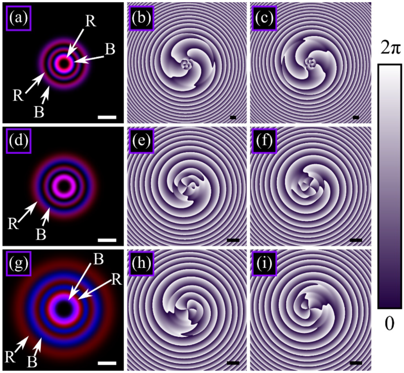
Figure 1 illustrates a superposition of two different-color LG beams. Intensity distributions (Figure 1a,d,g) are shown time-averaged, whereas the phase distributions (Figure 1b,c,e,f,h,i) are instantaneous (in two different time moments).
Since the TC of the blue beam exceeds that of the red beam, at small propagation distance, the blue ring has a larger radius than the red ring (Figure 1a). However, the red beam diverges more strongly than the blue beam. Therefore, at a distance of nearly 1 m, the rings’ radii are equal (one purple ring in Figure 1d), and, on further propagation, at a distance nearly 2 m, the red ring becomes outer, while the blue ring becomes inner (Figure 1g).
According to the theory, the common topological charge of the whole superposition does not depend on the color of the outer ring and is determined solely by the topological charge of the beam with a longer wavelength. Therefore, for the beam from Figure 1, it should be equal to three (TC = 3). Computation of the topological charge using the instantaneous phase distributions from Figure 1 confirms this; computing by M.V. Berry’s Equation (3) along a circle with the radius R1 = 7.5 mm yields the values 2.986 (Figure 1b), 2.982 (Figure 1c), 2.874 (Figure 1e,f), and 2.907 (Figure 1h,i).
In the initial plane and in the initial time moment, optical vortices in the beam cross-section are distributed in the following way: In the beam center on the optical axis, there is an optical vortex with the smallest TC of 3, whereas, at some radii from the axis, there is a vortex with a TC of +1 and, at greater radius, there is a vortex with TC of –1. After the evolution of such a superposition in time and in space, on the optical axis there is still a vortex with a TC of +3, while the optical dipole with TCs +1 and –1 on its ends approaches the optical axis. Thus, the TC of the superposition is equal to 3. This evolution can be seen in the instantaneous phase distributions in Figure 1. The vortices would behave differently, if, vice versa, the beam with a longer wavelength had the TC of 4 and the beam with a smaller wavelength had the TC of 3. Then, during the evolution of such a superposition, the vortex with the TC of –1 would move away to infinity “almost immediately”, and, near the axis, a vortex with the TC of 4 would be generated, and the whole superposition would have a TC equal to 4.
The same holds for multiple-ringed LG beams. In Figure 2, we show a superposition of two LG beams of different colors with the same parameters as in Figure 1, but the radial indices are p1 = p2 = 2 (each beam has three rings). To equate the beam powers, the weight coefficients of the superposition are chosen equal to c1 = [p1!/(n1 + p1)!]1/2 ≈ 0.053 and c2 = [p2!/(n2 + p2)!]1/2 ≈ 0.129.
Since the TC of the blue beam is greater than that of the red beam, at a small propagation distance, the radii of all three rings of the blue beam exceed the radii of the corresponding three rings of the red beam (Figure 2a). Since the red beam diverges more strongly than the blue beam, at a distance of nearly 1 m, the radii of the inner (most bright) rings become equal, and a single purple ring appears (Figure 2d), whereas the radii of the two outer red rings already exceed those of the blue outer rings. On further propagation, at a distance of nearly 2 m, all three red rings become outer with respect the to three blue rings (Figure 2g).
According to the theory, the presence of several rings and their radii do not affect the common topological charge of the whole superposition and, as in Figure 1, it should be equal to 3 (TC = 3). Computation of the topological charge by M.V. Berry’s formula using the instantaneous phase distributions from Figure 2 confirms this. Numerically obtained values are 2.987 (Figure 2b), 2.982 (Figure 2c), 2.874 (Figure 2e,f), and 2.907 (Figure 2h,i).

3.3. Numerical Simulation of a Three-Color Laguerre–Gaussian Vortex with Different Topological Charges

Here, we try, in a similar way, to construct a superposition of three Laguerre–Gaussian beams of three different colors that are spatially separated in the initial plane then add up in a single ring and form an optical vortex that looks white or gray (superposition of red, green, and blue beams) and then separate again. At a distance z from the initial plane, the radius of the maximal-intensity ring of each of these three vortices is equal to:
r max , s = w n s 2 1 + ( z z s ) 2 .
If these radii are almost equal for all three vortices, the following condition should be fulfilled:
n 1 [ 1 + ( z z 1 ) 2 ] n 2 [ 1 + ( z z 2 ) 2 ] n 3 [ 1 + ( z z 3 ) 2 ] .
It can be seen that three vortices cannot add up at small propagation distances (z << z1, z2, z3), since, in this case, their topological charges are nearly equal and, therefore, in the initial plane, these three rings cannot be spatially separated. Now, we suppose that the beams add up in the Fresnel diffraction zone, and the propagation distance is equal, for instance, to the average Rayleigh distance of the three beams. Let λ1 < λ2 < λ3. Then, since the waist radius is the same for all three beams, putting z = z2 in Equation (11), we get the following condition for the topological charges:
n 2 n 1 1 2 [ 1 + ( λ 1 λ 2 ) 2 ] , n 2 n 3 1 2 [ 1 + ( λ 3 λ 2 ) 2 ] .
For example, if the wavelengths of the interfering beams are equal to λ1 = 400 nm, λ2 = 550 nm, and λ3 = 700 nm, then n2/n1 ≈ 0.76 ≈ 3/4 and n2/n3 ≈ 1.31 ≈ 4/3. For example, we can choose n1 = 16, n2 = 12, and n3 = 9. However, these topological charges are small and, according to Equation (10), the radii of the maximal-intensity rings in the initial plane are close to each other: rmax,1 ≈ 2.83 w, rmax,2 ≈ 2.45 w, and rmax,3 ≈ 2.12 w. Since each ring has a thickness comparable to the waist radius w, these three rings are not spatially separated in the initial plane. Therefore, for computations, we increase the order of each beam four times: n1 = 64, n2 = 48, and n3 = 36.
Shown in Figure 3 are the time-averaged intensity distributions and instantaneous phase distributions of a superposition of three single-ringed LG beams of different colors.
Since, for the chosen parameters, the topological charge of the beams decreases with the wavelength, then, in the initial plane and at a small distance from it, the red ring is within the green ring, and the green ring is within the blue ring (Figure 3a,c). It is also seen that, due to the divergence on propagation, the borders between the beams (low-intensity rings) in Figure 3c become less distinct than in Figure 3a. Since the divergence of the beams increases with the wavelength, the red beam diverges most strongly and the blue beam most weakly. Choosing the topological charges according to Equation (12), at the Rayleigh distance of the green beam (z = z2 ≈ 1.43 m), all three beams have a light ring of the same radius, and, therefore, the diffraction pattern looks like a single white (light gray) ring (Figure 3e). On further propagation, due to the different divergence, the rings separate again, but, now, the blue ring becomes inner and the red ring becomes outer (Figure 3g).
According to the theory, the common topological charge of the whole superposition is equal to the topological charge of the beam with a longer wavelength. For the chosen parameters, it should be equal to TC = 36. An exception is the initial plane z = 0, where the TC = max{36, 48, 64} = 64. Numerical computation using the instantaneous phase distributions from Figure 3 in M.V. Berry’s Equation (3) over a circle with the radius R1 ≈ 9.3 mm yields the values 63.944 (Figure 3b), 35.847 (Figure 3d), 35.775 (Figure 3f), and 35.934 (Figure 3h), i.e., computation confirms the theoretical value TC = 36 in all transverse planes excepting the initial one. In the initial plane, the value TC = 64 was obtained, but even at z = z3/2 (half of the minimum of the three Rayleigh distances for the red beam), there are 28 vortices of the order –1 on the phase distribution (Figure 3d), and, therefore, the net topological charge is 36 (64 − 28).

3.4. Numerical Simulation of Three-Color Laguerre–Gaussian Vortex with Different Permutations of Light Rings Colors

In all the considered examples (Figure 1, Figure 2 and Figure 3), the topological charge of the beams decreases with the wavelength. Thus, it seems that the topological charge of the whole superposition is equal to the minimal topological charge rather than to the topological charge of the beam with the longest wavelength. In order to confirm the theoretical outcome that the topological charge is defined solely by the wavelength, below, we consider all possible permutations of the three colors and three topological charges. There are six such permutations.
Figure 4 depicts the time-averaged intensity distributions and instantaneous phase distributions of these six different superpositions of three single-ringed LG beams of different colors with different permutations of the topological charges.
According to the theory, the topological charge should be equal to 4, 2, and 1 on those figures where the red ring is respectively outer (Figure 4a,b,e,f), middle (Figure 4c,d,i,j), and inner (Figure 4g,h,k,l). Numerical computation using the instantaneous phase distributions from Figure 4 in M.V. Berry’s Equation (3) over a circle with the radius R1 ≈ 5 mm yields the values 3.996 (Figure 4a,b,e,f), 1.998 (Figure 4c,d,i,j), and 0.999 (Figure 4g,h,k,l), i.e., the computations confirm the corresponding theoretical values. In addition, the topological charge can be determined on the phase distributions visually. Each of the images in Figure 4b,f contain four optical vortices of the order +1, and, thus, the net total topological charge is TC = 4. In Figure 4d,j, in addition to the four vortices of the order +1, there are two vortices of the order–1, i.e., the net topological charge equals TC = 2. In Figure 4h,l, there are already three such vortices of the order–1, and, therefore, the net topological charge is TC = 1.
To demonstrate that the TC of the whole beam depends solely on the TC of the beam with the longer wavelength, we computed superpositions where the beams with shorter wavelengths have higher powers. Figure 5 illustrates the beams from Figure 4i–l, but the powers of the beams with λ1 = 400 nm and with λ1 = 550 nm are, respectively, three and two times larger than the power of the beam with λ1 = 700 nm (i.e., cs = as/(ns!)1/2 with a1 = 31/2, a2 = 21/2, a3 = 1).
It can be seen that the red component of both beams is weak, and the intensity distributions contain mostly blue and green areas. However, counting the vortices of orders +1 and –1 yields the topological charge TC = 2 for the beam in Figure 5a,b and TC = 1 for the beam in Figure 5c,d, i.e., the total TC is equal to the TC of the red beam. Numerical computation using the instantaneous phase distributions from Figure 5 in M.V. Berry’s Equation (3) over a circle with the radius R1 ≈ 5 mm confirms these values: 1.9987 (Figure 5a,b) and 0.9995 (Figure 5c,d).

3.5. Numerical Simulation of a Three-Color Superposition of the Laguerre–Gaussian Vortex with the Same Topological Charge

In the superpositions shown in Figure 1, Figure 2, Figure 3, Figure 4 and Figure 5, the constituent LG beams have different TCs. Therefore, in the initial plane, different-color rings have different radii. If the TC of all the constituent beams is the same, then such a multi-color beam consists of a single ring in the initial plane, and then, on propagation, spectral components split. Figure 6 demonstrates such a behavior for a superposition at three different transverse planes (in the initial plane, in the Fresnel diffraction area, and in the far field).
Figure 6 shows the topological charge of the beam computed along the red circles. It can be seen that it is slightly different in Figure 6a,b,c but close to its theoretical value of 25. Figure 6 also demonstrates that the light ring has the white color in the initial plane, but then, on propagation, acquires the form of a rainbow in the far field (red, green, and blue colors are clearly seen). Moreover, as the theory predicts, the longer wavelength leads to the larger ring radius.

3.6. Numerical Simulation of Paraxial Free-Space Space Propagation of a Three-Color Gaussian Beam Passed through a Spiral Phase Plate

We note that the generation of a multi-color superposition of several LG beams with the same TC is challenging. In practice, an optical vortex can be created by a spiral phase plate. This SPP is fabricated for a particular wavelength. If such a SPP is illuminated by a multi-color light, then each spectral component acquires its own TC, typically fractional. If an nth-order SPP is designed for the wavelength λ0 and illuminated by a light beam with the wavelength λ, then the transmittance function of the SPP for such a beam reads as exp(in λ0φ/λ) (φ is the polar angle). Thus, the beam with a longer wavelength acquires a smaller effective TC, neff = nλ0/λ. Therefore, it diverges more weakly than a beam with a shorter wavelength. However, despite the SPP, the divergence of a light beam generally increases with the wavelength. For instance, the width of a Gaussian beam with waist radius w0 at a distance z is w0{1 + [λz/(πw02)]2}1/2. These two opposite effects of decreasing and increasing divergence can compensate each other, and the beam can propagate without splitting into the spectral components.
Figure 7 and Figure 8 demonstrate this effect. Shown in these figures is a three-color Gaussian beam that passes through a third-order SPP and propagates in space to an area of the Fresnel diffraction (Figure 7) and to the far field (Figure 8). Figure 7 and Figure 8 are obtained by the Fresnel transform of a Gaussian beam with an optical vortex, i.e., each beam has the initial complex amplitude E(r, φ) = exp(–r2/w2 + ineffφ). The beam consists of blue, green, and red light, but the SPP is designed for the green light. Therefore, for blue and red components, the effective TC of the SPP neff is different (shown in Figure 7b,d,f and Figure 8b,d,f). Figure 7 and Figure 8 also contain the TC computed individually for each spectral component and for the entire multi-color beam. It is seen that it is equal to TC ≈ 3 in all cases except the blue beam in far field (Figure 8a). This is because some of the peripheral vortices of the first order are outside the area of the TC computation.
According to Figure 7a,e, since the initial topological charge of the blue and red vortices is fractional, then, instead of a ring, a distorted ring is generated (a dent at nearly +45 degrees and a gap at nearly –45 degrees). Therefore, the color of the multi-colored ring in Figure 7g changes along the ring. At angles of approximately +45 and –45 degrees, the color of the ring is pure green, whereas at angles of nearly –10 and –90 degrees, the ring is an orange color (since the red component overwhelms).
As seen in Figure 7 and Figure 8, indeed, the Gaussian beam is not split on propagation in space. However, due to the fractional order of the SPP for the blue and red light, these components do not contain the perfect light ring in contrast to the green light (Figure 7e and Figure 8e). Therefore, the resulting beam looks like a ring but with inhomogeneous color. For instance, the orange color in the bottom of the ring in Figure 8g is due to the bright spot in the red beam (Figure 8e) and due to the gap in the blue beam (Figure 8a).

3.7. FDTD Simulation of the Propagation a Three-Color Gaussian Beam through a Refractive Spiral Phase Plate and in the Near Field

Shown in Figure 9 is the SPP phase with order n = 3 and its 3D view.
The simulation of the light propagation through the SPP is carried out using the FDTD method. This method takes the SPP microrelief into account. The SPP is placed in the waist of three linearly polarized, coherent Gaussian beams with different wavelengths −488 nm, 532 nm, and 633 nm. The radius of the Gaussian beams is the same and equals 2.5 μm. The following are the simulation parameters: grid size in all three coordinates 17.7 nm, simulation area 8 × 8 × 2.5 μm, and the SPP material refractive index n = 1.5; the relief height h is calculated for the middle wavelength of λ0 = 532 nm and is equal to h = λ 0 / ( N 1 ) = 2 λ 0 .
Shown in Figure 10a–c are the period-averaged intensity distributions of a three-color Gaussian beam passed through a SPP (Figure 9) at different distances z: 0.532 µm, 2 µm, and 20 µm. For the chosen waist radius, the Rayleigh distance even for the red beam is nearly 31 μm, i.e., all the propagation distances are in the near field. At the same time, for the wavelength of 488 nm, blue shades are used: green shades for the wavelength of 532 nm, red for 633 nm. Each color corresponds to the color of the laser with a given wavelength. Figure 10d–f also shows the phase distributions of the beams with a wavelength of 488 nm, 532 nm, and 633 nm.
Three local maxima are seen in Figure 10 to have a green tint (Figure 10a) and a green-yellow tint (Figure 10b) at close distances. As the distance from the SPP increases, these local maxima “smooth out”, and the intensity distribution becomes like a triangle with three intensity zeros near the axis (triangular button). These three intensity nulls indicate the presence of three optical vortices. The topological charge of the three-color beam is 3. This is also seen from the phase distributions in Figure 10d–f.

4. Topological Charge of a White Optical Vortex

Here, we consider a practically important case where, in the waist plane of a white Gaussian beam, a single SPP is placed, the relief of which is matched with the wavelength λ0. Then, the complex amplitude of the superposition in the Fresnel diffraction zone is given by:
E ( ρ , θ , z , t ) = i z λ 0 0 λ 1 f ( λ ) d λ 0 r d r 0 2 π d φ × × exp { i 2 π z λ i 2 π c t λ r 2 w 2 + i n λ 0 λ φ } exp { i π λ z [ r 2 + ρ 2 2 r ρ cos ( φ θ ) ] } ,
with f(λ) being the envelope function of the spectrum of white-light source (e.g., LED). Actually, Equation (13) is a superposition of the Fresnel transforms [25] for different wavelengths. Since the TC of each monochromatic (single-color) vortex μ = n λ 0 / λ is, in general, fractional, then the integral over φ in Equation (13) cannot be evaluated. Therefore, we expand the exponent exp(iμφ) into a series of optical vortices with integers TCs:
exp ( i n λ 0 λ φ ) = e i π n λ 0 / λ λ sin ( π n λ 0 / λ ) π m = e i m φ n λ 0 m λ .
Substituting Equation (14) into Equation (13), we get:
E ( ρ , θ , z , t ) = 2 i z λ 0 m = ( i ) m e i m θ 0 e i ( π / λ ) ( n λ 0 + ρ 2 / z + 2 z 2 c t ) sin ( π n λ 0 / λ ) f ( λ ) n λ 0 m λ d λ × 0 exp ( r 2 w 2 + i π r 2 λ z ) J m ( 2 π r ρ λ z ) r d r ,
with Jm(x) being the mth-order Bessel function of the first kind. The integral over the variable r in Equation (15) can be evaluated by using a reference integral from [26]:
0 r d r exp ( r 2 w 2 + i π r 2 λ z ) J m ( 2 π r ρ λ z ) = π 3 / 2 ρ w 3 ( λ z ) 1 / 2 ( sgn m ) | m | 4 ( λ z i π w 2 ) 3 / 2 e ξ [ I ( | m | 1 ) / 2 ( ξ ) I ( | m | + 1 ) / 2 ( ξ ) ] ,
where ξ = ( π ρ w ) 2 / [ 2 λ z ( λ z i π w 2 ) ] .
Substituting Equation (16) into Equation (15), we finally obtain:
E n ( ρ , θ , z , t ) = i π 3 / 2 ρ w 3 2 z 1 / 2 λ 0 m = ( i ) m ( sgn m ) | m | e i m θ D m , n ( ρ , z , t ) ,
where
D m , n ( ρ , z , t ) = 0 e ξ [ I ( | m | 1 ) / 2 ( ξ ) I ( | m | + 1 ) / 2 ( ξ ) ] ( λ z i π w 2 ) 3 / 2 × e i ( π / λ ) ( n λ 0 + ρ 2 / z + 2 z 2 c t ) λ 1 / 2 sin ( π n λ 0 / λ ) f ( λ ) n λ 0 m λ d λ .
The integral (18) can hardly be reduced to a reference integral, and, therefore, it cannot be evaluated in an explicit form, excepting a trivial case of a monochromatic light when f ( λ ) = δ ( λ λ 0 ) . In this case, expression (17) coincides with Equation (45) from [24]. However, even without evaluating Equation (18), some conclusions can be drawn from the obtained expressions (17) and (18). Namely, if there is zero denominator of the integrand, then only some terms remain in the series (17), i.e., those terms, the numbers of which, m, yield this zero denominator:
m = n λ 0 λ , λ [ λ 0 Δ λ , λ 0 + Δ λ ] ,
with 2Δλ being the width of the spectrum of the colored Gaussian beam. For instance, if n = 10, λ0 = 532 nm, and Δλ = 100 nm, then only four terms remain in Equation (17), and their numbers are m = 9, 10, 11, and 12. Further, Equation (1) can be used. This expression indicates that the superposition contains, effectively, only four beams, and the TC of the whole superposition is equal to the maximal TC, i.e., TC = 12. If the SPP order is increased two times, i.e., n = 20, then, in the same example, Equation (17) contains eight colored optical vortices with numbers m from 17 to 24. This means that Equation (17) contains, effectively, eight optical vortices (1), and the TC of such a superposition is equal to TC = 24. On the contrary, if the SPP order is decreased, e.g., n = 3, then, as in [16], for a beam with an arbitrary wavelength from the range (432 nm, 632 nm), only one term in Equation (17) becomes zero at m = 3. This explains the experimental results from [16] where, after passing through a single SPP of the order n = 3, all colored vortices (white, blue, red, and green) have a TC equal to m = 3.

5. Experiment

In this section, we describe an experiment generating a superposition of two optical vortices with the same TC. Figure 11 shows an optical setup for the experiment. Gaussian beams with almost equal waist radii are emitted by two lasers with wavelengths of 532 nm and 633 nm. We note that, despite the theoretical part of the work, the vortex beams are superimposed coherently; due to the difference in the wavelengths, the intensity of the superposition is equal to the sum of the intensities of each beam, as in Equation (9). Similarly, the intensity of the superposition of two beams from different lasers in the experiment is also equal to the sum of the intensities of each beam. Both beams, after the beam-splitting cube BS, propagate along the same path to SLM. The amplitude transmission function of the SLM is shown in Figure 12a. It can be seen that the hologram on the SLM is a fork grating. After passing through the SLM, laser beams acquire an orbital, angular momentum and a topological charge (TC = 25). Figure 12b,c depicts separate intensities of both beams immediately after the aperture D. It can be seen that both rings have approximately the same radius. Figure 12d illustrates the intensity of both beams that passed through the SLM simultaneously and are registered without a wedge. Due to dispersion on the grating (Figure 12a), the red ring propagates at a larger angle to the optical axis than the green one. It can also be seen (Figure 12d) that the red ring has a larger radius than the green one. This is because the divergence of a Gaussian beam is proportional to the wavelength. In Figure 12e, we try to use a wedge to compensate for the grating dispersion and combine both rings. However, since the wedge angle is not consistent with the grating period (Figure 12a), the alignment of the rings is incomplete. From Figure 12d,e, it can be seen that, in the areas where both beams intersect, the intensity color is yellow. This means that the beams add by intensity (without interference). This experiment is consistent with the simulation result in Figure 6.

6. Conclusions

Thus, in this study we investigated different variants of a coaxial superposition of the Laguerre–Gaussian beams with different wavelengths. Using the well-known M.V. Berry formula, we derived the topological charge of a coaxial superposition of two Laguerre–Gaussian beams of different colors, each with its own wavelength and its own TC. It turned out that the TC of such a superposition equals the TC of the LG beam with a longer wavelength (more red), regardless of the weight coefficient of this beam in the superposition and regardless of the TC of this beam. This TC derivation can be generalized to a superposition of an arbitrary finite number of the LG beams with different wavelengths, both single-ringed and multiple-ringed. At this, the TC of the whole superposition is equal to the TC of the constituent LG beam with the longer wavelength. This result was confirmed numerically for a superposition of three single-ringed beams and for a superposition of two three-ringed beams. Since the phase velocities of the beams were different, the transverse intensity section of the beam changed on propagation with a velocity proportional to the difference between the maximal and minimal wavelengths. At the same time, the instantaneous TC of such a superposition was conserved, while the intensity distribution (time-averaged) of the “colored” optical vortex changed its light “gamut”. For example, for a two-color superposition, if, in the near field, the colors of the light rings (rainbow) arrange along a radius according to their TCs in the superposition from lower to greater, then, on space propagation (in the far field), the colors of the light rings in the rainbow are arranged in reverse order from the greater TC to the lower TC. It was also demonstrated that, by appropriately choosing the wavelengths (blue, green, and red) in a three-color superposition of single-ringed LG beams, it is possible to generate, at some distance, a time-averaged light ring of the white color.
Thus, we hope the obtained results are significant for stably identifying incoming optical signals when they a carried by multi-color light beams.

Author Contributions

Conceptualization, V.V.K.; methodology, A.A.K.; formal analysis, V.V.K.; software, A.A.K. and A.G.N.; experiment, S.S.S.; writing—original draft preparation, A.A.K.; writing—review and editing, V.V.K. All authors have read and agreed to the published version of the manuscript.

Funding

The work was funded by the Russian Science Foundation (grant 22-22-00265).

Institutional Review Board Statement

Not applicable.

Informed Consent Statement

Not applicable.

Data Availability Statement

Not applicable.

Conflicts of Interest

The authors declare no conflict of interest.

References

  1. Kotlyar, V.V.; Kovalev, A.A. Topological Charge of Optical Vortices; Novaya Tekhnika: Samara, Russia, 2021. [Google Scholar]
  2. Gbur, G.; Tyson, R.K. Vortex beam propagation through atmospheric turbulence and topological charge conservation. J. Opt. Soc. Am. A 2008, 25, 225–230. [Google Scholar] [CrossRef] [PubMed]
  3. Li, J.; Zeng, J.; Duan, M. Classification of coherent vortices creation and distance of topological charge conservation in non-Kolmogorov atmospheric turbulence. Opt. Express 2015, 23, 11556–11565. [Google Scholar] [CrossRef] [PubMed]
  4. Yang, W.; Situ, G. Recovery of the topological charge of a vortex beam propagated through a scattering layer. Appl. Opt. 2021, 60, B95–B99. [Google Scholar] [CrossRef] [PubMed]
  5. Kotlyar, V.V.; Kovalev, A.A.; Amiri, P.; Soltani, P.; Rasouli, S. Topological charge of two parallel Laguerre-Gaussian beams. Opt. Express 2021, 29, 42962–42977. [Google Scholar] [CrossRef]
  6. Pu, M.; Li, X.; Ma, X.; Wang, Y.; Zhao, Z.; Wang, C.; Hu, C.; Gao, P.; Huang, C.; Ren, H.; et al. Topological charge of two parallel Laguerre-Gaussian beams. Sci. Adv. 2015, 1, 1500396. [Google Scholar] [CrossRef] [Green Version]
  7. Ponomarenko, S.A.; Wolf, E. Spectral anomalies in a Fraunhofer diffraction pattern. Opt. Lett. 2002, 27, 1211–1213. [Google Scholar] [CrossRef]
  8. Berry, M.V. Coloured phase singularities. New J. Phys. 2002, 4, 66. [Google Scholar] [CrossRef]
  9. Leach, J.; Padgett, M. Observation of chromatic effects near a white-light vortex. New J. Phys. 2003, 5, 154. [Google Scholar] [CrossRef]
  10. Volyar, A.V.; Fadeeva, T.A. Generation of singular beams in uniaxial crystals. Opt. Spectrosc. 2003, 94, 235–244. [Google Scholar] [CrossRef]
  11. Angelsky, O.V.; Maksimyak, A.P.; Maksimyak, P.P.; Hanson, S.G. Interference diagnostics of white-light vortices. Opt. Express 2005, 13, 8179–8183. [Google Scholar] [CrossRef]
  12. Arkhelyuk, O.O.; Polyanskii, P.V.; Ivanovskii, A.A.; Soskin, M.S. Creation and diagnostics of stable rainbow optical vortices. Opt. Appl. 2004, 34, 419–426. [Google Scholar]
  13. Denisenko, V.; Shvedov, V.; Desyatnikov, A.S.; Neshev, D.N.; Krolikovski, W.; Volyar, A.; Soskin, M.; Kivshar, Y.S. Deter-mination of topological charges of polychromatic optical vortices. Opt. Express 2009, 17, 23374–23379. [Google Scholar] [CrossRef] [PubMed]
  14. Hakobyan, D.; Magallanes, H.; Seniutinas, G.; Juodkazis, S.; Brasselet, E. Tailoring Orbital Angular Momentum of Light in the Visible Domain with Metallic Metasurfaces. Adv. Opt. Mater. 2015, 4, 306–312. [Google Scholar] [CrossRef]
  15. Kobashi, J.; Yoshida, H.; Ozaki, M. Polychromatic Optical Vortex Generation from Patterned Cholesteric Liquid Crystals. Phys. Rev. Lett. 2016, 116. [Google Scholar] [CrossRef]
  16. Zhang, Y.; Guo, H.; Qiu, X.; Lu, X.; Ren, X.; Chen, L. LED-based chromatic and white-light vortices of fractional topological charges. Opt. Commun. 2020, 485, 126732. [Google Scholar] [CrossRef]
  17. Tokizane, Y.; Oka, K.; Morita, R. Supercontinuum optical vortex pulse generation without spatial or topological-charge dis-persion. Opt. Express 2009, 17, 14517–14525. [Google Scholar] [CrossRef]
  18. Anderson, M.E.; Serrano, A.; Stinson, C.; Talamantes, A.; Miller, N.; Chaloupka, J.L. Spatial Manipulation of a Supercontinuum Beam for the Study of Vortex Interference Effects. Appl. Sci. 2020, 10, 1966. [Google Scholar] [CrossRef] [Green Version]
  19. Siegman, A.E. Lasers; University Science Books: Mill Valley, CA, USA, 1986. [Google Scholar]
  20. Kotlyar, V.V.; Elfstrom, H.; Turunen, J.; Almazov, A.A.; Khonina, S.; Soifer, V. Generation of phase singularity through diffracting a plane or Gaussian beam by a spiral phase plate. J. Opt. Soc. Am. A 2005, 22, 849–861. [Google Scholar] [CrossRef]
  21. Vallone, G. On the properties of circular beams: Normalization, Laguerre-Gauss expansion, and free-space divergence. Opt. Lett. 2015, 40, 1717–1720. [Google Scholar] [CrossRef] [Green Version]
  22. Vallone, G. Role of beam waist in Laguerre-Gauss expansion of vortex beams. Opt. Lett. 2017, 42, 1097–1100. [Google Scholar] [CrossRef]
  23. Berry, M.V. Optical vortices evolving from helicoidal integer and fractional phase steps. J. Opt. A Pure Appl. Opt. 2004, 6, 259–268. [Google Scholar] [CrossRef]
  24. Kotlyar, V.V.; Kovalev, A.A.; Volyar, A.V. Topological charge of a linear combination of optical vortices: Topological compe-tition. Opt. Express 2020, 28, 8266–8281. [Google Scholar] [CrossRef] [PubMed]
  25. Goodman, J.W. Introduction to Fourier Optics, 2nd ed.; McGraw-Hill: New York, NY, USA, 1996. [Google Scholar]
  26. Kölbig, K.S.; Prudnikov, A.P.; Bryckov, Y.A.; Maricev, O.I. Integrals and Series of Special Functions; CRC Press: Boca Raton, FL, USA, 1986. [Google Scholar] [CrossRef]
Figure 1. Distributions of time-averaged intensity (a,d,g) and of instantaneous phase (b,c,e,f,h,i) of a superposition of two single-ringed LG beams of different colors (λ1 = 400 nm, λ2 = 700 nm) at a distance z = 0.2 m (ac), z = 1 m (df), z = 2 m (gi) and at time moments t1 = 60 s (b,e,h) and t2 = 61 s (c,f,i). Other computation parameters are the following: Gaussian beam waist radius w = 500 μm, TCs n1 = 4 and n2 = 3, radial indices p1 = p2 = 0 (single-ringed beams), superposition weight coefficients c1 = [p1!/(n1 + p1)!]1/2 ≈ 0.2 and c2 = [p2!/(n2 + p2)!]1/2 ≈ 0.4 (so that both beams are of the same power). Scaling mark in each figure shows 1 mm. Symbols ‘R’ and ‘B’ (a,g) show areas where, respectively, red and blue beams dominate.
Photonics 09 00145 g001
Figure 2. Distributions of time-averaged intensity (a,d,g) and of instantaneous phase (b,c,e,f,h,i) of a superposition of two three-ringed LG beams of different colors. All parameters are the same as in Figure 1, but the radial indices are p1 = p2 = 2, and the superposition weight coefficients are c1 ≈ 0.053 and c2 ≈ 0.129. Scaling mark in each figure shows 1 mm. Symbols ‘R’ and ‘B’ (a,g) show areas where, respectively, red and blue beams dominate.
Photonics 09 00145 g002
Figure 3. Distributions of time-averaged intensity (a,c,e,g) and of instantaneous phase (b,d,f,h) of a superposition of three single-ringed LG beams of different colors (λ1 = 400 nm, λ2 = 550 nm, λ3 = 700 nm) at a distance z = 0 m (a,b), z = z3/2 ≈ 0.56 m (c,d), z = z2 ≈ 1.43 m (e,f), and z = 2z1 ≈ 3.93 m (g,h) and at a time moment t = 60 s. Other computation parameters are the following: Gaussian beam waist radius w = 500 μm, topological charges n1 = 64, n2 = 48, and n3 = 36, radial indices p1 = p2 = p3 = 0, superposition weight coefficients cs = 1/(ns!)1/2, s = 1,2,3 (so that all the beams are of the same power). Scaling mark in each figure shows 1 mm. Symbols ‘R’, ‘G’, and ‘B’ (a,c,g) show areas where, respectively, red, green, and blue beams dominate. Symbol ‘W’ (e) shows a white (light gray) ring, generated by addition of all three beams.
Photonics 09 00145 g003
Figure 4. Distributions of time-averaged intensity (a,c,e,g,i,k) and of instantaneous phase (b,d,f,h,j,l) of six different superpositions of three single-ringed LG beams of different colors (λ1 = 400 nm, λ2 = 550 nm, λ3 = 700 nm) at a distance z = z2/2 ≈ 0.71 m (half of the Rayleigh distance of the beam with the average wavelength) and at a time moment t = 60 s. Other computation parameters are the following: Gaussian beam waist radius w = 500 μm, topological charges n1 = 1, n2 = 2, and n3 = 4 (a,b), n1 = 1, n2 = 4, and n3 = 2 (c,d), n1 = 2, n2 = 1, and n3 = 4 (e,f), n1 = 2, n2 = 4, and n3 = 1 (g,h), n1 = 4, n2 = 1, and n3 = 2 (i,j), n1 = 4, n2 = 2, and n3 = 1 (k,l), radial indices p1 = p2 = p3 = 0, superposition weight coefficients cs = 1/(ns!)1/2, s = 1,2,3 (so that all the beams are of the same power). Scaling mark in each figure shows 1 mm. Symbols ‘R’, ‘G’, and ‘B’ (a,c,g) show areas where, respectively, red, green, and blue beams dominate. Red symbols ‘+’ and ‘–’ in the phase distributions show the optical vortices of the orders +1 and –1.
Photonics 09 00145 g004
Figure 5. Distributions of time-averaged intensity (a,c) and of instantaneous phase (b,d) of two different superpositions of three single-ringed LG beams of different colors. All parameters are the same as in Figure 4i,j (a,b) and as in Figure 4k,l (c,d), but the superposition weight coefficients are equal to cs = as/(ns!)1/2 with a1 = 31/2, a2 = 21/2, a3 = 1, s = 1,2,3 (so that the blue and green beams are, respectively, three and two times more powerful than the red beam).
Photonics 09 00145 g005
Figure 6. Distributions of time-averaged intensity (ac) and of instantaneous phase (df) of a superposition of three single-ringed LG beams of different colors (λ1 = 488 nm, λ2 = 532 nm, λ3 = 633 nm) with the same TC at different distances and at a time moment t = 60 s. Other computation parameters are the following: Gaussian beam waist radius w = 500 μm, topological charge n1 = n2 = n3 = 25, propagation distances z = 0 (a,d), z = z0/2 ≈ 0.74 m (b,e) (z0 is the Rayleigh distance of the beam with the average wavelength 532 nm), and z = 5z0 ≈ 7.38 m (c,f), radial indices p1 = p2 = p3 = 0, superposition weight coefficients cs = 1, s = 1,2,3 (all the beams are of the same power). Scaling mark shows 1 mm (a,b,d,e) and 10 mm (c,f). Symbols ‘R’, ‘G’, and ‘B’ (e) show areas where, respectively, red, green, and blue beams dominate.
Photonics 09 00145 g006
Figure 7. Distributions of time-averaged intensity (a,c,e,g) and of instantaneous phase (b,d,f,h) of a separate spectral components (af) and of entire three-color Gaussian beam (g,h) diffracted by a SPP at a distance z = z0/2 ≈ 0.74 m (z0 is the Rayleigh distance of the beam with the average wavelength 532 nm). Other computation parameters are the following: wavelengths λ1 = 488 nm (a,b), λ2 = 532 nm (c,d), λ3 = 633 nm (e,f), Gaussian beam waist radius w = 500 μm, topological charge of the SPP n = 3, wavelength for which the SPP was designed λ0 = 532 nm, time moment t = 60 s. Scaling mark in all figures shows 1 mm. The TC was numerically computed along the red, dashed circles (b,d,f,h).
Photonics 09 00145 g007
Figure 8. Distributions of time-averaged intensity (a,c,e,g) and of instantaneous phase (b,d,f,h) of a separate spectral components (af) and of entire three-color Gaussian beam (g,h) diffracted by a SPP at a distance z = 5z0 ≈ 7.38 m. Other computation parameters are the same as in Figure 7. Scaling mark in all figures shows 10 mm.
Photonics 09 00145 g008
Figure 9. The SPP phase and its 3D view.
Photonics 09 00145 g009
Figure 10. The beam intensity after passing through the phase plate at different distances (ac) and the phase of the Gaussian beam with wavelength 488 nm (d), 532 nm (e), 633 nm (f) at a distance of 532 nm.
Photonics 09 00145 g010
Figure 11. Experimental setup: Laser 532—MGL-F-532–700 mW (λ = 532 nm, 700 mW); Laser 633—Cobolt 06-MLD laser (λ = 633 nm, 200 mW); M2—mirror; BS—beam-splitter cube; PH—pinhole; O1—100× objective lens; P1, P2—linear polarizers; amplitude-only SLM—spatial light modulator (Holoeye LC 2012); L1, L2—lenses (f1 = 100 mm, f2 = 50 mm); D—diaphragm to block the zero diffraction order; CCD—CCD camera (UCMOS 10,000 KPA).
Photonics 09 00145 g011
Figure 12. Transmission function of the amplitude SLM (a); optical vortices with TC = 25 near the SLM: red (b) and green (c); intensity of the both beams passed along the same path through the SLM before the wedge (d) and after the wedge (e).
Photonics 09 00145 g012
Publisher’s Note: MDPI stays neutral with regard to jurisdictional claims in published maps and institutional affiliations.