Article

The Optimization of a Convex Aspheric Lightweight SiC Mirror and Its Optical Metrology

Changchun Institute of Optics, Fine Mechanics and Physics, Chinese Academy of Sciences, Dong-Nanhu Road 3888, Changchun 130033, China
*
Author to whom correspondence should be addressed.
Photonics 2022, 9(4), 210; https://doi.org/10.3390/photonics9040210 (registering DOI)
Submission received: 10 February 2022 / Revised: 18 March 2022 / Accepted: 18 March 2022 / Published: 23 March 2022

Abstract

:
Space telescopes with large diameters or with wide fields require convex secondary mirrors which are mounted at the front of telescope. In this paper, a convex aspheric lightweight SiC mirror and Hindle detection method are presented. A parameter optimization method is utilized in the mirror design process in which the mirror surface accuracy is taken as the objective. As the mirror has a relative high diameter-to-thickness ratio, an S-type flexure support is proposed to maintain the surface figure under gravity, thermal change and assembly error. To minimize the surface figure under these loads, the design principle is studied separately. The optical metrology is performed by the Hindle ball supported by a gravity offloading system. The tested surface had an accuracy of λ/100 root mean square (λ = 632.8 nm). In addition, the mechanical design was validated by dynamic testing.

1. Introduction

With the development of astronomy, military and space technology, requirements for the performance of optical systems are increasing. Aspherical surfaces used in optical instruments can improve the image quality and optical characteristics, simplify the instrument structure, and reduce the weight and overall size [1]. Because aspherical surfaces have only one axis of symmetry and the curvature of each zone is different, surface metrology is difficult. When designing a space mirror assembly, the mirror is weight-limited and flexure is used to resist external environmental disturbances, such as gravity, assembly error, and thermal change, and disturbance during launch [2,3]. However, compared with a concave mirror, the design and surface metrology are more complicated [4].
As the secondary mirror assembly is mounted at the front of the telescope, its mass is limited. However, weight reduction also reduces the rigidity of the mirror, and the surface distortion under gravity increases. Manufacturing tolerances on parallelism between the mounting interfaces imposes the requirement that each support accommodate a fixed angular displacement in any orientation during assembly. The resulting moment on the mirror must not cause excessive mirror surface distortion. Due to the differences in coefficients of thermal expansion, the thermal changes during ground testing and the in-orbit environment will cause differential thermal expansion or contraction between the mirror and the baseplate. For the optical performance to remain unaffected by environmental influences, a flexure must be compliant enough to absorb these external loads passively [5]. The launch environment, on the other hand, imposes the requirement on the flexure that the maximum stress during launch must not exceed the micro-yield of the material [6]. A flexure satisfying that requirement is necessarily stiff, which can be estimated by the fundamental frequency. The flexible support is the key component to reduce optical distortion and ensure the quality of remote sensing images.
Mirror flexure supports can be divided into three main forms [7,8,9]: passive supporting forms, gravity unloading forms and active optical forms. The passive support is a traditional support method. The commonly used back three-point support belongs to the passive support form. This method has been implemented on many different apertures of mirrors in different projects, where the invar sleeve is attached to the mount with flexure to match the coefficient of thermal expansion of the mirror material. The back support structure has the advantages of lightweight and small size. Moreover, a mirror supported on the mid-plane can minimize gravitational optical distortion [10,11,12].
At present, the detection of a large-aperture aspherical surface adopts three main methods: null lens detection, Hindle ball detection and computational hologram (CGH) detection. Hindle ball detection is the earliest, most common, and most reliable detection method. It is mainly used to detect convex aspherical surfaces, and has the advantages of high detection accuracy and simple assembly and adjustment [13].
In the present study, a lightweight SiC rectangular mirror is designed for a space telescope based on the back three-point support scheme. An S-type flexure hinge is presented to balance the lateral gravity of the mirror, and its size parameters are optimized. The design principle of the flexible support is studied. Then material of the mirror blank is reaction-bonded SiC. The optical performance of the mirror assembly is evaluated by finite element analysis. The design is optimized to realize zero-gravity surface figure stability under lateral gravity. Then the secondary mirror assembly is fabricated, assembled, and polished. A Hindle ball is designed to test the surface shape of the mirror. Optical testing and vibration tests are performed on the mirror assembly to validate the flexure design. And the test shows that the engineering requirements have been met.

2. Performance Metrics

The design specifications of the secondary mirror assembly include the mirror surface shape error, decenter, tilt, mass and frequency, as shown in Table 1. The comprehensive surface accuracy index is decomposed into independent specifications according to the disturbance type. In this way, the comprehensive surface accuracy specification can be satisfied when each sub-index meets the requirements separately. The disturbances include gravity, thermal change, the flatness error of the mounting surface, and axial mount accuracy, and they are all considered in the design process of the space mirror assembly [14].
In actual engineering, the causes of these four disturbances are different and approximately unrelated. The following error synthesis formula of random error and systematic error can be used to calculate the total error.
σ = i = 1 q σ i 2 + j = 1 s s j 2
where σ i is the random error and s j is the single undetermined system error.
Given the current fabrication ability of optical mirror surfaces, processing precision of machining parts and the installation accuracy of the mirror assembly, the total error budget of λ/100 (6.3 nm) was decomposed into four components (including some margin) [15], as shown in the Figure 1. The total RMS of 6.3 nm is decomposed into 2.5 nm for gravity. The surface distortion caused by the forced displacement of 0.05 mm on the mounting surface is not more than 4 nm. When the temperature change is 4 °C, the allowed degradation of surface accuracy is 2 nm, as shown in Figure 1. The allowed degradation of the surface shape caused by machining and assembly errors is 3.6 nm.

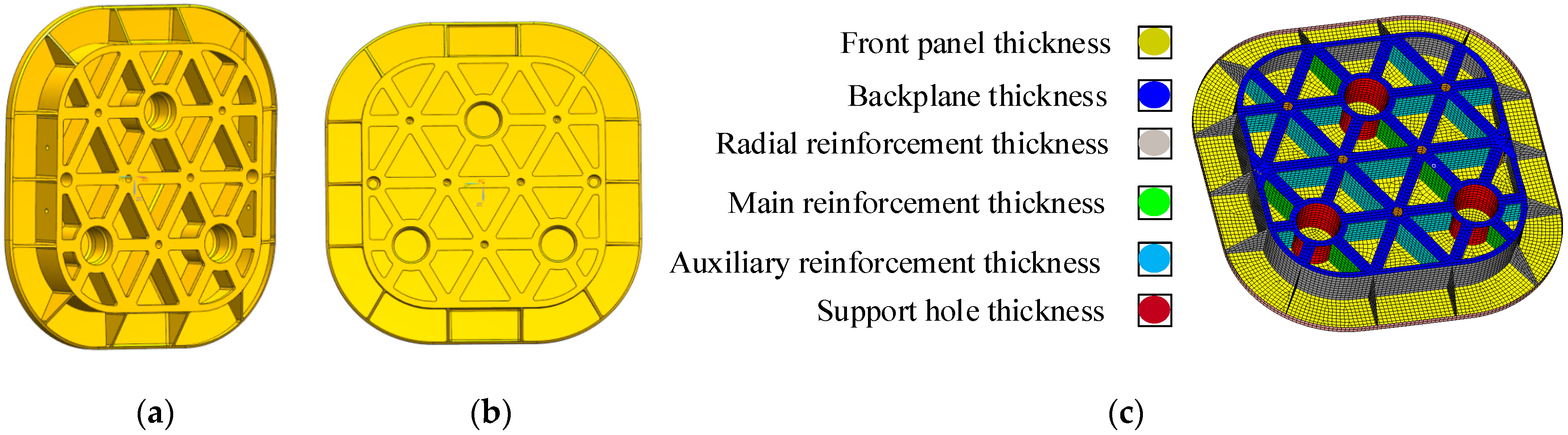
3. Lightweight Design of the Rectangular Mirror

A partially closed-back monolithic, 434 × 416 mm rectangular SiC mirror configuration was examined. The central thickness of the mirror is 50 mm. The mirror is supported by three supporting holes located on its back. The graduation circle diameter of the three support holes is 224 mm, the thickness of the front panel is 4 mm. These structural sizes were determined by empirical equations [16,17]. For fabrication simplicity and better thermal performance, the mirror is designed as a symmetric structure. The initial thicknesses of the ribs were set to 3 mm. The mirror after initial design is shown in Figure 2a,b.
The parametric design method was applied to the lightweight design of the mirror based on the traditional lightweight design. The shell element mesh model of the secondary mirror was established by HyperMesh software. The established grid was grouped according to the initial design results and the symmetry of the mirror structure, as shown in Figure 2c. Each group corresponds to an optimization variable. Among them, it mainly includes the thickness of front panel, Back plane, main reinforcement, auxiliary reinforcement, surrounding radiation reinforcement and support holes.
Isight software was used to combine multiple interdisciplinary models and applications into a simulation process. Through automatic execution across distributed computing resources, the resulting design space was explored, and the optimal design parameters that meet the required constraints were determined [18,19]. The secondary mirror parameter optimization link built by Isight is shown in Figure 3a. Using Multi-Island GA algorithm [20], the parametric design was completed by integrating Optistruct and MATLAB software. The RMS value of the surface accuracy under 1 g gravity with the mirror’s optical axis horizontally was taken as the objective function and the mass as the constraint. The variation range of each variable is shown in Table 2. The optimization curve of RMS value of objective function is shown in Figure 3b. After parameter optimization, the mirror surface shape error RMS is 0.597 nm and the mass is 4.6 kg. The three-dimensional model after parameter optimization is shown in Figure 4a, and the surface cloud diagram is shown in Figure 4b. Figure 5 shows that the relationship between the mirror mass and the mirror surface shape error RMS is a quadratic curve. For low mass mirrors the shape error decreases with the increase in mirror stiffness; When the mirror mass increases to the lowest point of surface accuracy (mass: 4.8 kg), the change in surface error remains almost stable.

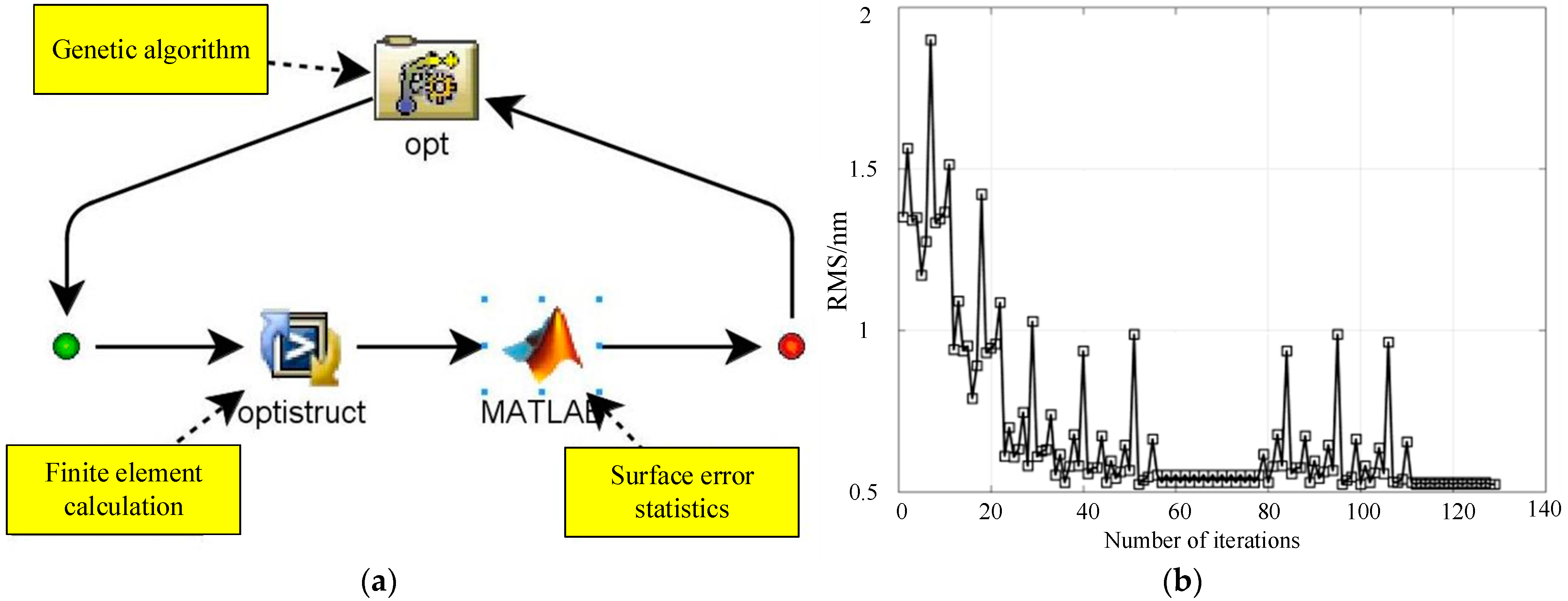
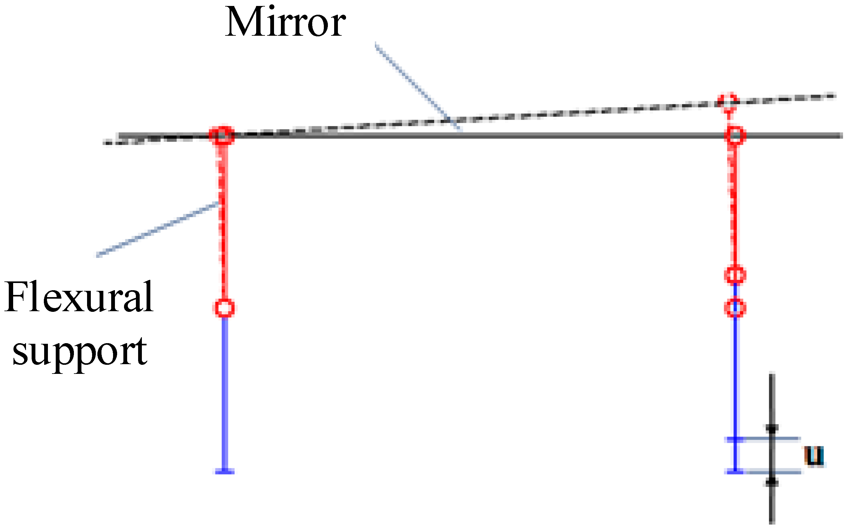
4. Optimal Design of the S-Type Flexure

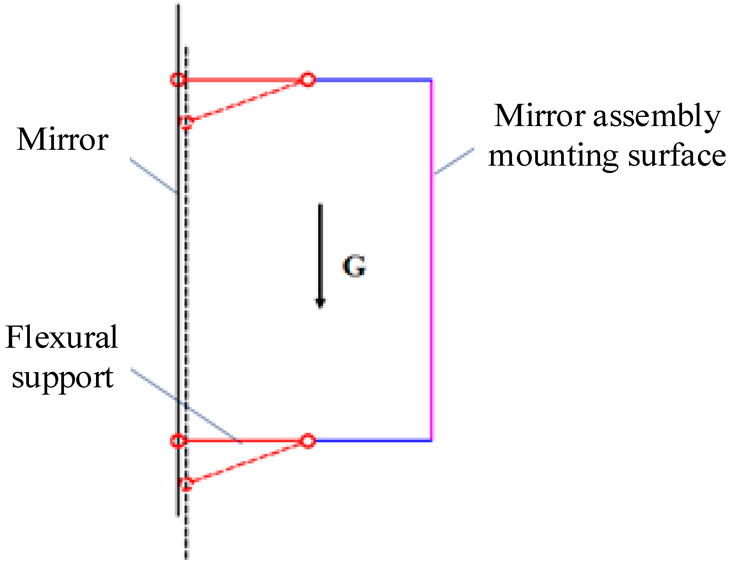
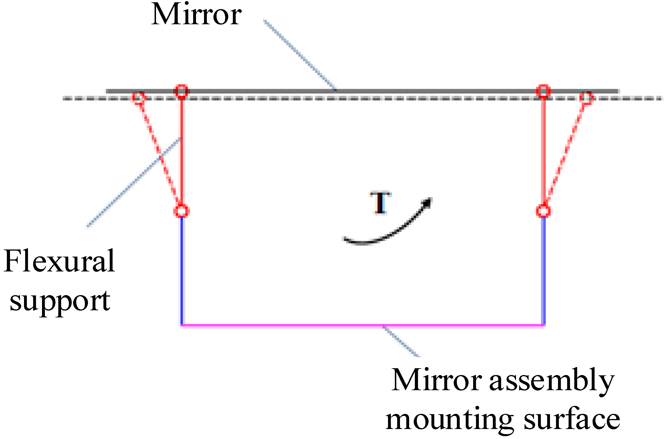
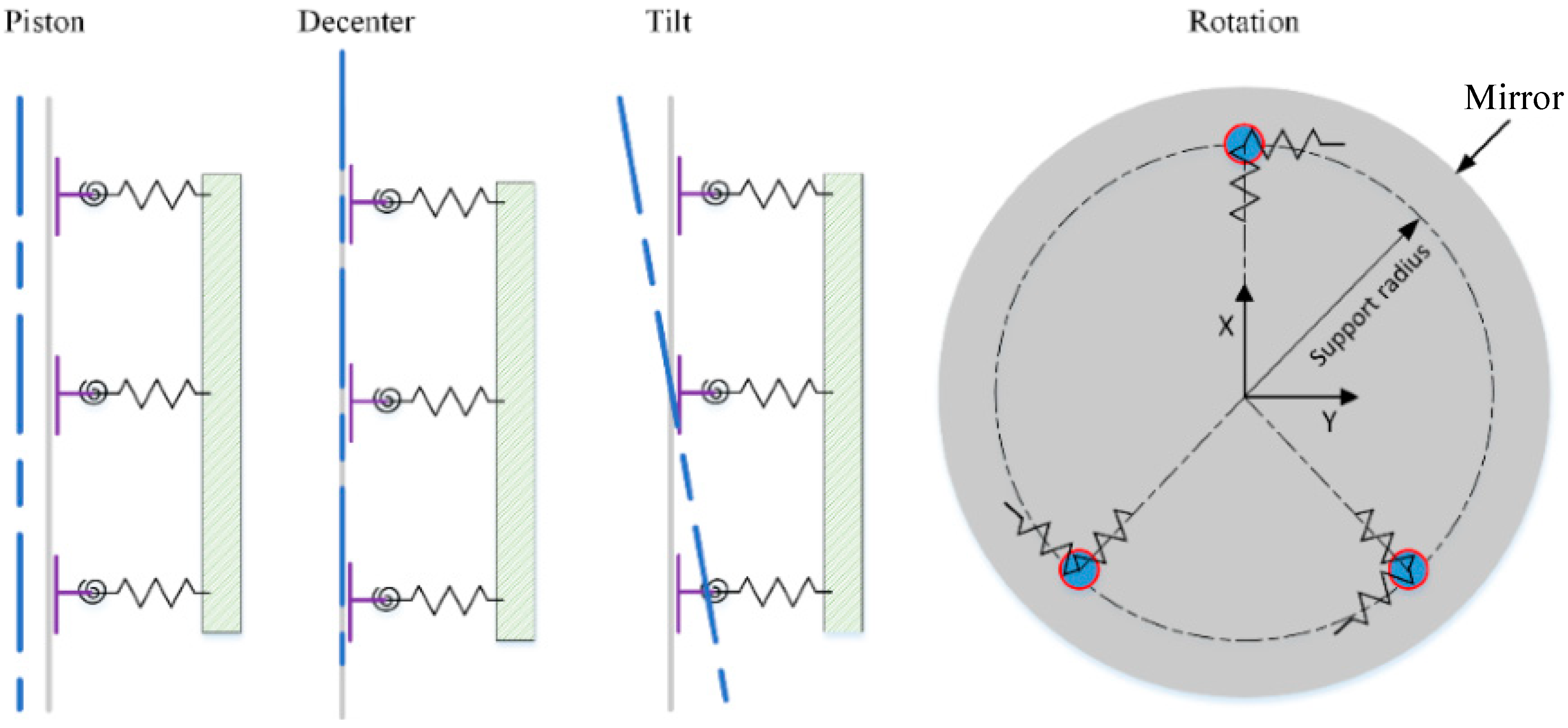
4.1. Design Principle of the Three-Point Support Flexure

The flexible support for the mirror can unload its self-weight while positioning the mirror and alleviate the influence of thermal stress on the mirror, so as to reduce mirror deformation. The flexure should also be able to alleviate the sensitivity of the mirror assembly surface shape to assembly error, avoid the generation of large, concentrated force in the process of force transmission, and finally, minimize the deformation of the mirror. Due to the actual working conditions of the mirror, the flexible support must have the following capabilities [14].

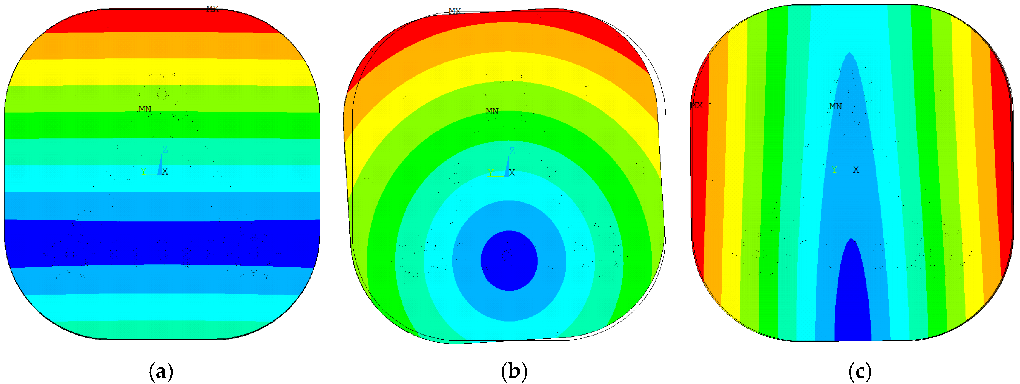
4.1.1. Unloading Gravity Load

A deformation diagram of the mirror assembly under gravity load is shown in Figure 6. We need flexible supports with high stiffness to ensure that the mirror has minimal translation and rotation under the action of gravity to ensure the positioning accuracy of the mirror. The three group flexible supports have the same stiffness in the gravity direction, which can evenly offset the gravity of the mirror and ensure that the mirror body will not produce large local deformation. The surface shape error of the mirror assembly under 1 g gravity load is related to the support position of the flexible support in the optical axis direction of the mirror. In the design of a support to reduce the influence of gravity on surface shape error, we should start with the support position of the flexible support in the optical axis direction.

4.1.2. Relieve Temperature Load

Our aim is to reduce the sensitivity of mirror surface shape resulting from temperature change. The mirror assembly with three-point support on the back is usually composed of the mirror, the flexure and a cone sleeve. The functional requirements of the various parts are different, so their materials are also different. When the temperature load changes, the deformation of each part is different due to the different linear expansion coefficients of the materials, and consequently, the mirror surface shape is changed, as shown in Figure 7. In order to reduce the influence of temperature load on the mirror surface shape error, the support needs to be flexible in its radial direction.

4.1.3. Improve the Adaptability to Assembly Errors

The mirror assembly must adapt to machining and assembly errors. The non-flatness error of the component mounting plane and the deformation of the mounting plane will affect the surface shape error of the mirror. A schematic diagram of the components affected by the above errors is shown in Figure 8. This requires that the front face of the flexible support has a certain rotation capacity, and the non-coplanarity error is transformed into the rigid motion of the mirror, so as to reduce the influence of the surface error.

4.1.4. Improve Structural Stability and Frequency

The stiffness of the mirror is greater than that of the flexible support. The first three modes of the mirror assembly are the rigid motion of the mirror, which is determined by the flexibility characteristics of the flexible support. Generally, the shear stiffness of the mirror is greater than the bending stiffness, that is, the surface error of the mirror under the action of a shear force is less than that under the action of a bending moment. In order to reduce the transmission of bending moments to the mirror, the rotational flexibility of the flexible support is generally greater than the translational flexibility. The vibration modes of the first three modes of the three-point support mirror assembly are generally translation, eccentricity, inclination, and rotation around the optical axis. Among them, the rotation mode around the optical axis has little contribution to the dynamic response of the mirror assembly. The frequencies of translation, eccentricity, and tilt modes should be increased to reduce the dynamic stress and improve the structural stability. The relationship between the flexibility of the flexible support and the vibration modes of the mirror assembly is shown in Figure 9. The translation and tilt modes are related to the axial flexibility of the flexible support. The greater the axial flexibility stiffness, the higher the frequency of the translation and tilt modes. According to the previous analysis, the axial stiffness has nothing to do with the shape error under the action of gravity, assembly error, or temperature. The axial stiffness should be maximized in the design of a flexible support. The eccentric mode is related to the translational flexibility of the flexible support. The smaller the translational flexibility, the higher the frequency of the eccentric mode will be. According to the previous analysis, the translational flexibility is related to the rigid body displacement due to gravity and the surface shape error due to temperature. A compromise must be found in the design of the translational flexibility of the flexible support.
Based on the above requirements for the flexible support, it can be seen that, in order to reduce the surface degradation of the mirror assembly in the working environment, targeted design of the direction and size of the flexibility of the flexible support structure is necessary. The front end of the flexible joint must have the ability of translation along the radial direction and rotation in a certain range. At the same time, the flexible support needs to have a certain stiffness to ensure that the dynamic characteristics and rigid body displacement of the component meet the technical index requirements.

4.2. Structural Design of Flexure

According to the design principle and requirements of the flexible support, the flexure structure shown in the Figure 10 was obtained. The flexure is divided into flexible part (green part) and rigid part (blue part). The flexible part is composed of a necked, S-type flexible groove, which provides rotation and radial translation. At the same time, it is used to balance the contradiction between the stiffness and flexibility required by the mirror assembly. The rigid part is mainly used to adjust the overall length of the flexure to ensure the connection with the mounting plane. Each flexure is designed to take one third of the mirror’s weight.
To improve the thermal stability, three invar sleeves, which have the same expansion coefficient as the SiC material, were bonded to the internal surface of the supporting holes using epoxy adhesive (GHJ-01(Z)) in a 120-degree interval. The thickness of the applied epoxy was 10 μm which is controlled by hollow microspheres. The 10 μm microspheres were firstly mixed evenly with adhesive at a mass fraction of 3%. Then the mixture was applied at the bonding area. The mirror is supported by three titanium alloy flexures through the supporting holes located on its back, as shown in Figure 10. The flexure mounting may be regarded as a semi-kinematic design because it has a finite contact area, and it provides controlled motion through elastic deformation. The flexure is attached to sleeves and the adjustment mechanism by screws.
In general, to minimize the surface distortion when the mirror is measured horizontally, the pivot center of the mounting flexures is located on the neutral surface, as shown in Figure 11. At this time, no moments will be transferred to the mirror, and the mirror has the best surface accuracy. The neutral surface is the collection of points where the elastic bending properties of the mirror substrate and the moments due to reaction forces balance to minimize optical distortions. The surface of each working condition is shown in Table 3, and the surface cloud diagram is shown in Figure 12. The vibration mode of the first three frequencies of the mirror assembly is shown in Figure 13. The comprehensive surface shape of the mirror assembly is 4.06 nm and the fundamental frequency is 271.6 Hz. Each performance meets the index requirements.

5. Optical and Vibration Testing

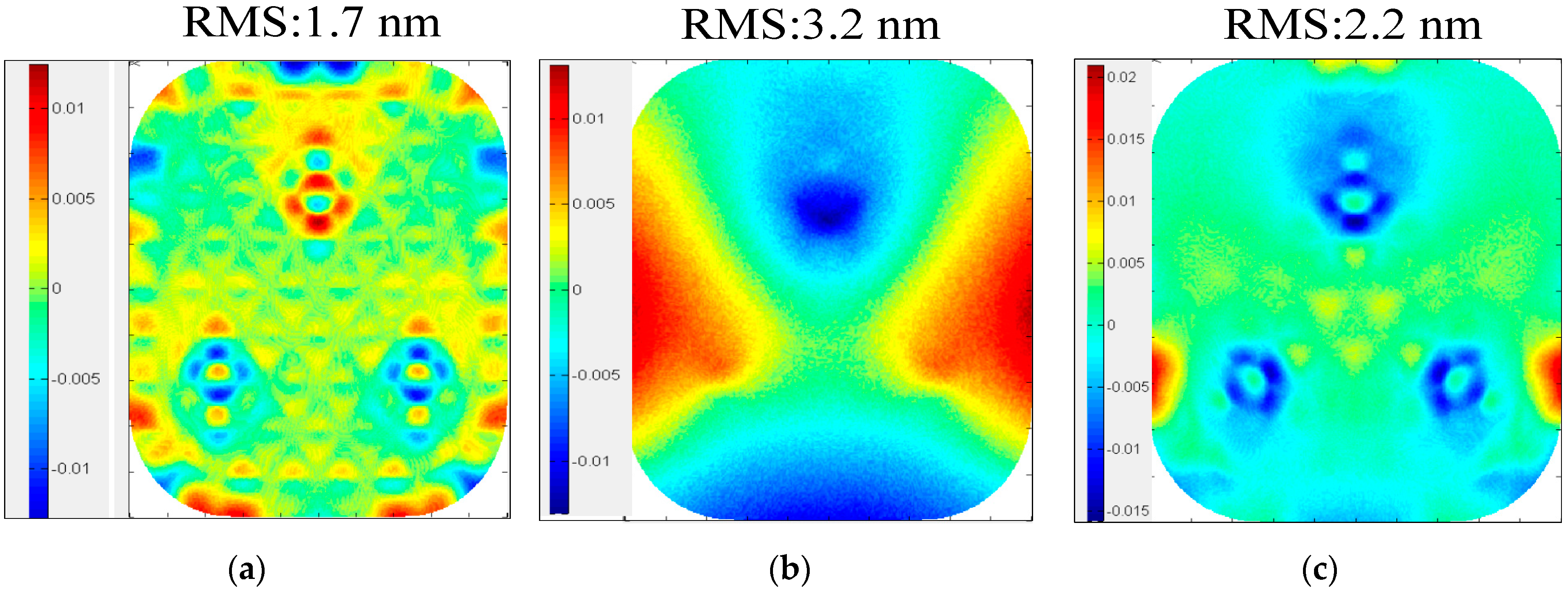
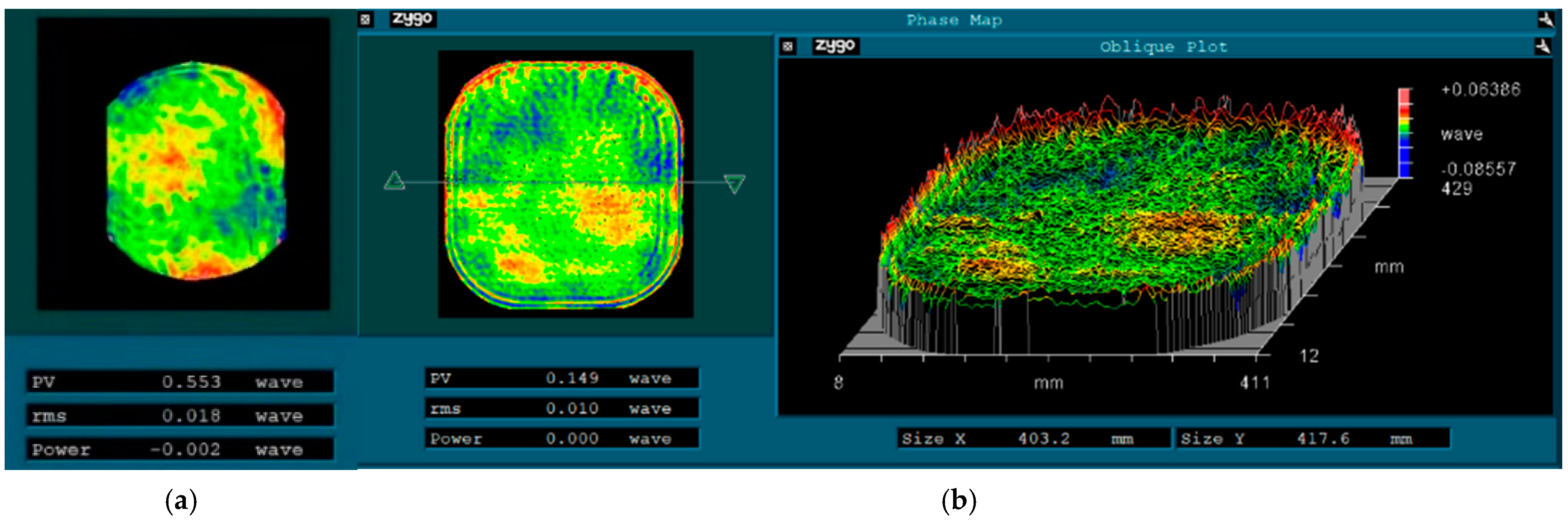
5.1. Optical Testing

The Hindle compensation test system for off-axis convex aspherical surfaces was built to perform optical testing of the secondary mirror assembly. The null compensation principle of the Hindle test method directly takes the focus property of the hyperboloids as the conjugated aberration-free point. The testing optical path of the convex mirror with the Hindle ball is shown in Figure 14.
An optical test platform was built as shown in Figure 15. A Zygo interferometer was used to test the mirror accuracy with its optical axis horizonal. When testing, the loads acting on the mirror assembly include gravity, a temperature load of 24℃ based on a room temperature 20℃, and a non-flatness error of 0.05 mm. The mirror achieved an accuracy of 0.010λ at 0°, and 0.011λ after rotating 180°around its optical axis. The shape error test of the mirror and Hindle ball is shown in Figure 16.

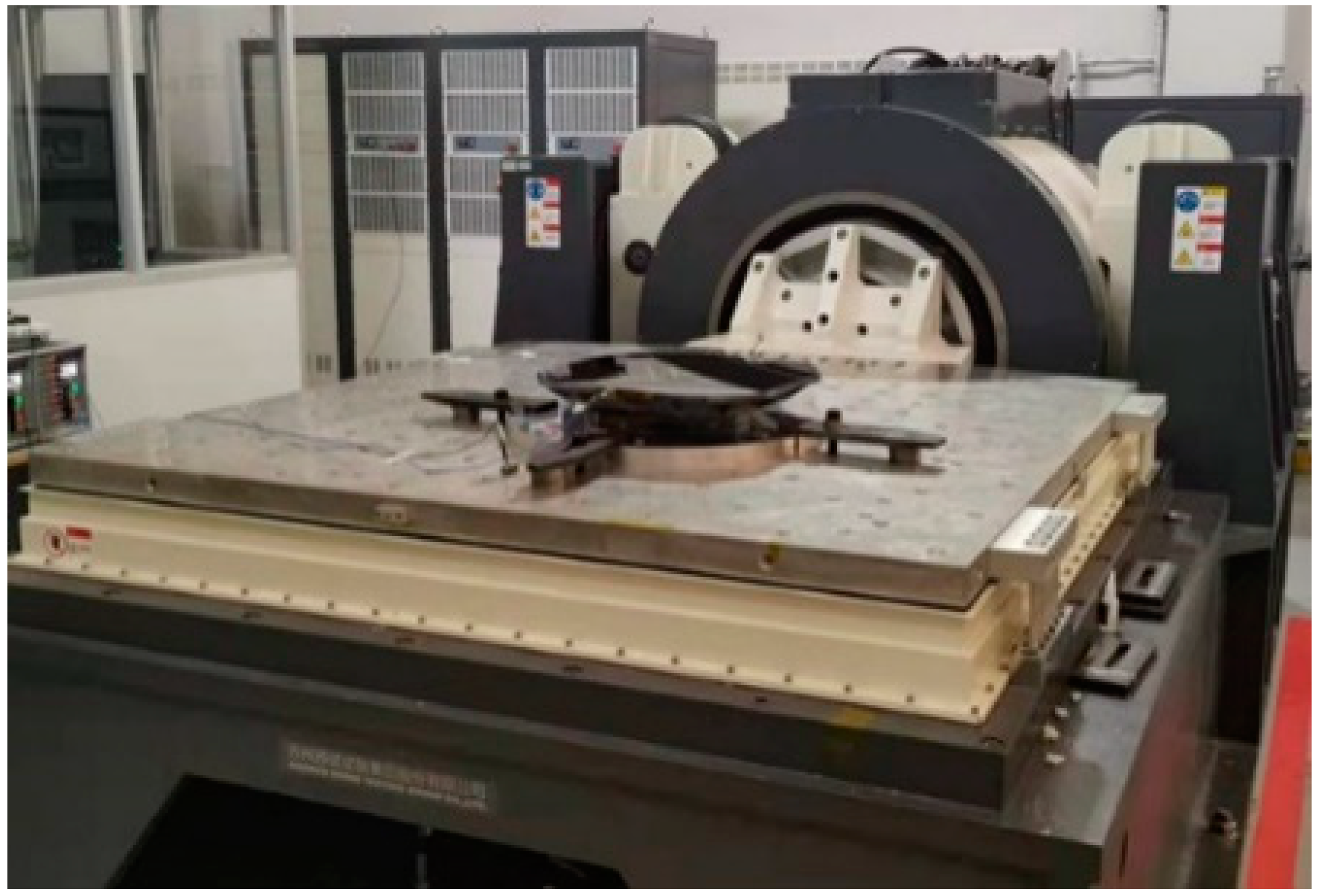
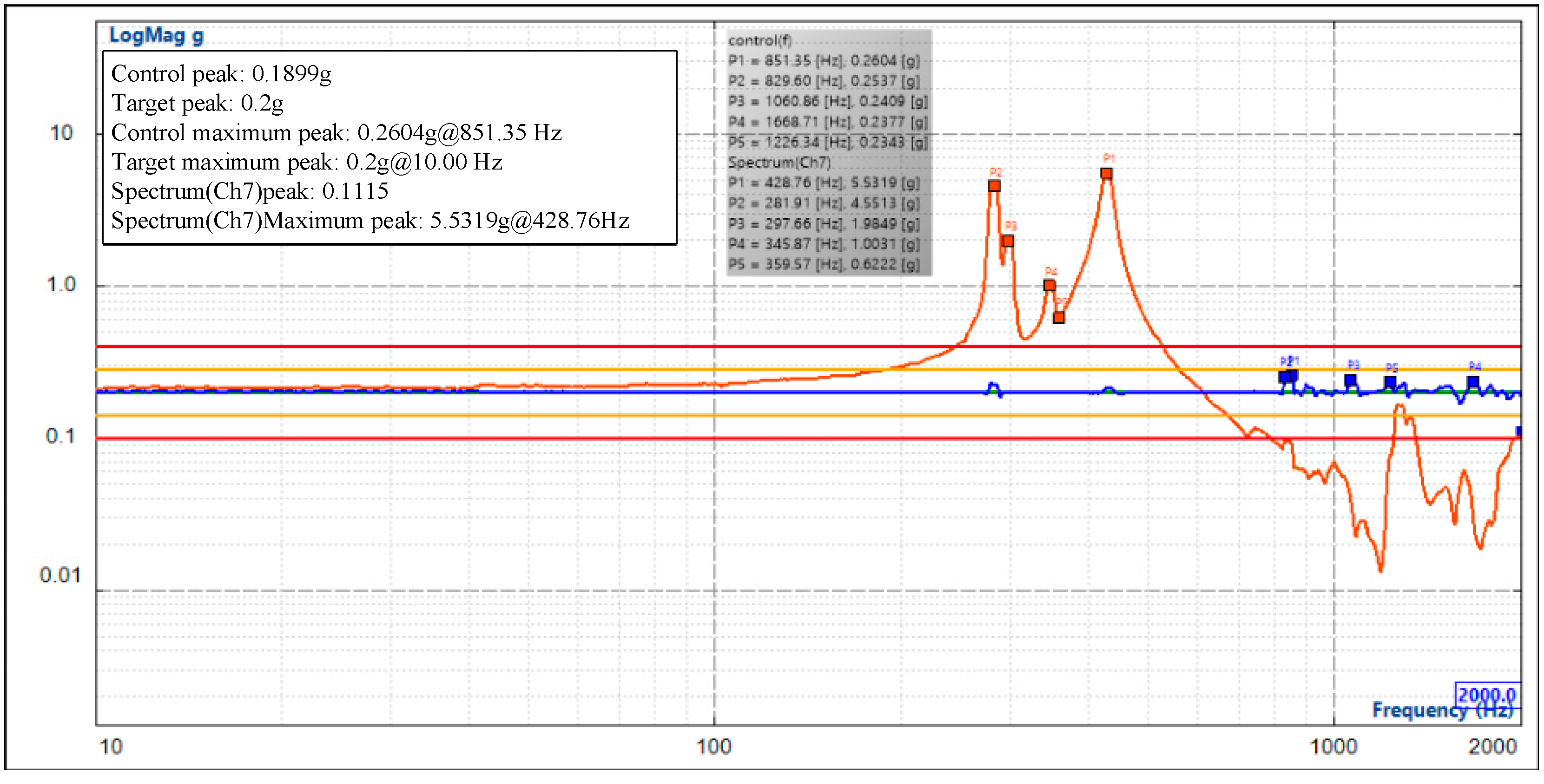
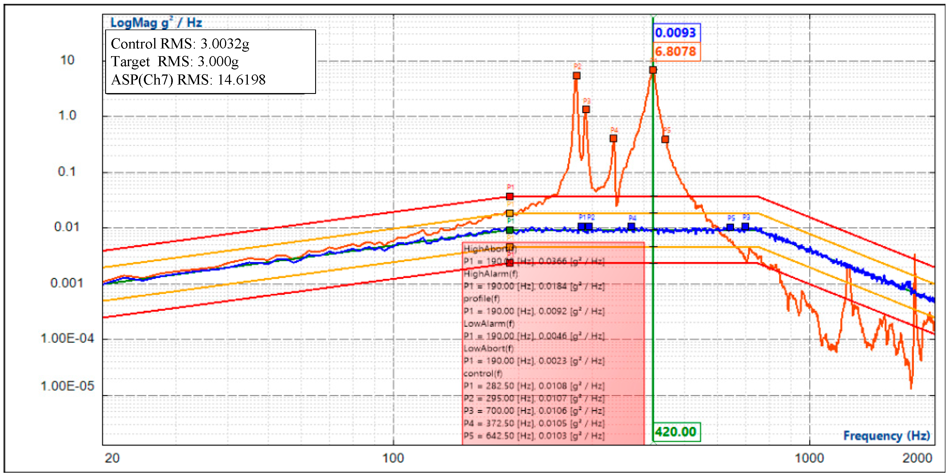
5.2. Vibration Testing

Before and after acceptance of the optical test, a vibration test on the secondary mirror assembly was performed, including a 0.2 g sweep sine test, sine vibration (quasi-static load), and 3 g rms random vibration. The mirror assembly was tested under the above vibration loads in the X, Y and Z directions. (Y/Z are lateral and X is along the optical axis). The mirror assembly passed the acceptance tests, as shown in Figure 17. The vibration results of the sweep sine and random test are shown in Figure 18 and Figure 19, respectively. The fundamental frequency was 281.9 Hz. By comparing the finite-element analysis results shown in Figure 13 (271.6 Hz) and the sweep sine test results shown in Figure 18, the structural design of the mirror assembly was verified. The analysis result has a deviation of 3.7% from the test result. To ensure that no change had occurred in the mirror accuracy, the optical test was performed before and after the dynamic tests. The optical test showed that the mirror accuracy had no visible change. Therefore, the structural stiffness and stability of the mirror assembly were verified.

6. Conclusions

We presented a delicately designed 434 × 416 mm rectangular convex SiC mirror assembly for a sky-survey space telescope. An S-type flexible support was proposed based on the back three-point support principle. Through parameter optimization, optical performance analysis, mechanical performance analysis, optical testing, and vibration validation, the design method and optical metrology were verified. All the challenges for the optical design and mechanical loads have been met. The support shows extraordinary performance in that the surface figure can maintain λ/100 RMS (λ = 632.8 nm) under 1 g lateral gravity. The test results prove that the mirror’s surface accuracy can remain better than λ/100 RMS in orbit under zero-gravity so that the image quality of the optical system can be guaranteed.

Author Contributions

Conceptualization, P.Z.; methodology, P.Z.; software, P.Z.; validation, P.J.; formal analysis, P.Z.; investigation, P.J.; resources, P.Z.; data curation, P.J.; writing—original draft preparation, P.J.; writing—review and editing, P.J.; visualization, P.J. All authors have read and agreed to the published version of the manuscript.

Funding

This research was funded by the program of the key technology that multipoint passive support of the space-based large-aperture mirror is compatible with active support, grant number 11703027), which comes from National Natural Science Foundation of China.

Institutional Review Board Statement

Not applicable.

Informed Consent Statement

Not applicable.

Data Availability Statement

Not applicable.

Acknowledgments

The authors would like to thank National Natural Science Foundation of china.

Conflicts of Interest

The authors declare no conflict of interest.

References

  1. Betensky, E. The role of asphere in zoom lens design. SPIE 1990, 1354, 656–662. [Google Scholar]
  2. Qu, Y.; Jian, Y.; Feng, L.; Li, X.; Liu, B. Lightweight design of multiobjective topology for a large-aperture space mirror. Appl. Sci. 2018, 8, 2259. [Google Scholar] [CrossRef] [Green Version]
  3. Bely, P. The Design and Construction of Large Optical Telescopes; Springer: New York, NY, USA, 2003; pp. 1–28. [Google Scholar]
  4. Pan, J.H. The Design Manufacture and Test of the Aspherical Optical Surfaces; Suzhou Soochow University Press: Suzhou, China, 2004; pp. 51–61. [Google Scholar]
  5. Hagyong, K.; Ho-Soon, Y.; Il Kweon, M.; Jeong-Heum, Y.; Seung-Hoon, L.; Yun-Woo, L. Adjustable bipod flexures for mounting mirrors in a space telescope. Appl. Opt. 2012, 51, 7776–7783. [Google Scholar]
  6. Xiong, G.H.; Liao, K.; Chang, X.Y.; Liu, J.A. Deformation Control by VSR Technique on Al alloy Thin-Walled Components. IOP Conf. Ser. Mater. Sci. Eng. 2017, 11, 269. [Google Scholar] [CrossRef] [Green Version]
  7. Wang, K.J.; Dong, J.H.; Xuan, M. Compound support structure for large aperture mirror of space remote sensor. Opt. Precis. Eng. 2016, 27, 1719–1730. [Google Scholar] [CrossRef]
  8. Yoder, P.R. Opto-Mechanical System Design; Cooperate Marcel Dekker Inc.: New York, NY, USA, 1993. [Google Scholar]
  9. Xue, J.; Hu, H.B.; Song, H.Z. Research on the flexible supporting structure of the optical reflector. J. Chang Chun Univ. Technol. 2009, 30, 457–461. [Google Scholar]
  10. Liu, X.; Tian, X.; Zhang, W.; Cheng, L.F.; Zhang, B.; Wang, Z. Lightweight design of high volume SiC/Al composite mirror for remote camera. Optik 2019, 188, 64–70. [Google Scholar] [CrossRef]
  11. Yu, F.; Xu, S. Flexible support structure based on spring principle for a high precision reflecting mirror. Optik 2020, 207, 164341. [Google Scholar] [CrossRef]
  12. Li, Z.X.; Chen, S.; Jin, G. Optimal design of a Φ760 mm lightweight SiC mirror and the flexural mount for a space telescope. Rev. Sci. Instrum. 2017, 88, 125107. [Google Scholar] [CrossRef] [PubMed]
  13. Wang, P.; Zhao, W.C.; Hu, M.Y.; Zhang, H.H.; Hao, P.M. Hindle testing of the off- axis convex ashpere surface. Opt. Precis. Eng. 2002, 10, 2. [Google Scholar]
  14. Wang, K.J.; Dong, J.H.; Zhao, Y.G.; Chi, C.Y.; Jiang, P.; Wang, X.Y. Research on high performance support technology of space-based large aperture mirror. Optik 2021, 226, 165929. [Google Scholar] [CrossRef]
  15. Zhou, P.W.; Xu, S.Y.; Yan, C.X.; Zhang, X.H. Research on neutral surface of lightweight, horizontally supported mirror. Opt. Eng. 2018, 57, 025107. [Google Scholar] [CrossRef]
  16. Valente, T.M.; Vukobratovich, D. A comparison of the merits of open-back, symmetric sandwich, and contoured back mirrors as light-weighted optics. Proc. SPIE 1989, 1167, 20–36. [Google Scholar]
  17. Abdulkadyrov, M.A.; Vladimirov, N.M.; Dobrikov, N.S.; Patrikeev, V.E.; Semenov, A.P. Optimizing design and manufacturability of reduced-weight mirrors for astronomy and space applications. J. Opt. Technol. 2016, 83, 168–172. [Google Scholar] [CrossRef]
  18. Li, Y.; Jiao, M.; Luo, C. Optimized design of lightweight flat mirror based on Isight. J. Appl. Opt. 2010, 31, 194–197. [Google Scholar]
  19. Hu, R.; Liu, S.; Li, Q. Topology-optimization-based design method of flexures for mounting the primary mirror of a large-aperture space telescope. Appl. Opt. 2017, 56, 4551–4560. [Google Scholar] [CrossRef] [PubMed]
  20. Zhang, J.J.; Xu, L.W.; Gao, R.Z. Multi-island genetic algorithm optimization of suspension system. Telkomnika 2012, 10, 1685–1691. [Google Scholar] [CrossRef]
Figure 1. Schematic illustration of the performance metrics.
Photonics 09 00210 g001
Figure 2. (a) The 3D model of the mirror, (b) top view of the mirror, and (c) parametric analysis model and parameter grouping of secondary mirror.
Photonics 09 00210 g002
Figure 3. (a)The Isight linkage of secondary mirror parameter optimization, (b) the optimal curve of objective function.
Photonics 09 00210 g003
Figure 4. (a) The secondary mirror obtained by lightweight design. (b) The surface distortion (RMS = 0.597 nm) due to lateral gravity.
Photonics 09 00210 g004
Figure 5. The relationship between RMS value and mass of the mirror.
Photonics 09 00210 g005
Figure 6. Schematic diagram of deformation of the mirror under the action of the flexible support in 1 g gravity.
Photonics 09 00210 g006
Figure 7. Schematic diagram of mirror deformation with a flexible support under temperature load.
Photonics 09 00210 g007
Figure 8. Schematic diagram of the influence on mirror deformation when the mounting surface of flexible support is not coplanar.
Photonics 09 00210 g008
Figure 9. The relationship between modal vibration shape of mirror assembly and compliance of flexible support.
Photonics 09 00210 g009
Figure 10. Exploded view of predesigned square SiC mirror assembly showing the symmetries, invar sleeve, gravity orientation, and illustration of the adopted flexure configuration.
Photonics 09 00210 g010
Figure 11. Schematic diagram of the position relationship between the pivot center of the flexure and the neutral surface of the mirror when the gravity surface shape of the mirror is optimal.
Photonics 09 00210 g011
Figure 12. The results show that the surface of the mirror assembly under different working conditions. (a) 1 g gravity (b) 0.08 mm forced displacement (c) 4 ℃ temperature.
Photonics 09 00210 g012
Figure 13. The modal shapes of the first 3 modes, (a) F1 = 271.6 Hz, (b) F2 = 279.4 Hz, and (c) F3 = 290.1 Hz.
Photonics 09 00210 g013
Figure 14. Hindle null compensation test method.
Photonics 09 00210 g014
Figure 15. Test of mirror accuracy (a) Mirror surface shape test (b) Hindle ball test.
Photonics 09 00210 g015
Figure 16. (a) Optical testing result of Hindle ball (b) Optical testing result of mirror assembly.
Photonics 09 00210 g016
Figure 17. Vibration test of the secondary mirror assembly in the Y direction (lateral). The mirror surface is covered by a protective layer. The accelerometer was attached on the back surface of the mirror.
Photonics 09 00210 g017
Figure 18. The sweep sine test result of the mirror assembly.
Photonics 09 00210 g018
Figure 19. V The random vibration response of the mirror assembly.
Photonics 09 00210 g019
Table 1. The design indices of secondary mirror assembly.
Design IndexesIndex Requirements
Mirror surface accuracyλ/100
Decenter0.017 mm
Tilt0.2″
Mass (mirror assembly)≤10 kg
Frequency≥150 Hz
Dynamic stress≤800 Mpa (the microyield stress)
Table 2. Geometric parameters of the lightweight mirror.
ParameterParameter Variation RangeOptimized Value
Diameter 434 × 416 mm
Main reinforcement thickness3–44 mm
Auxiliary reinforcement thickness3–43 mm
Radial reinforcement thickness3–43 mm
The front panel thickness4~54 mm
Mirror thickness45~6050 mm
Backplane thickness4~65 mm
Support hole thickness4–76.5 mm
Total mass 4.6 kg
Lightweight ratio 81.6%
Table 3. The design results of different design indices.
Design IndexResultAllowed Value
1 g gravity1.61 nm2.0 nm
rigid body displacement0.00198 mm0.017 mm
inclination angle0.125″0.2″
4 °C thermal change1.75 nm2.5 nm
forced displacement of 0.05 mm3.30 nm4.0 nm
comprehensive surface4.06 nm (λ/155)6.3 nm (λ/100)
fundamental frequency271.6 Hz150 Hz
Publisher’s Note: MDPI stays neutral with regard to jurisdictional claims in published maps and institutional affiliations.

