Article

Large Mode Area Single Mode Fiber with a Twisted Polygon-Shaped Core

1
School of Mechanical Science and Engineering, Huazhong University of Science and Technology, Wuhan 430074, China
2
Wuhan National Laboratory for Optoelectronics, Huazhong University of Science and Technology, Wuhan 430074, China
3
School of Materials Science and Engineering, Huazhong University of Science and Technology, Wuhan 430074, China
4
Guangdong Intelligent Robotics Institute, Dongguan 523830, China
*
Author to whom correspondence should be addressed.
Photonics 2022, 9(4), 221; https://doi.org/10.3390/photonics9040221
Submission received: 12 March 2022 / Revised: 25 March 2022 / Accepted: 26 March 2022 / Published: 28 March 2022
(This article belongs to the Section Lasers, Light Sources and Sensors)

Abstract

:
We present numerical studies on twisted polygon-shaped core fibers for achieving single mode operation with a large mode area propagation in this paper. These large mode area fibers can achieve single mode operation due to twisting-induced high losses to higher order modes and coupling higher order modes with leaky modes. A tail-like profile will appear in higher order modes when they couple with leaky modes, and the tail-like profile also indicates that these modes carry angular momentum. Numerical simulations show that twisted octagon-shaped core fiber with a core diameter of 80 μm can obtain first higher order mode losses larger than 19 dB/m while maintaining fundamental mode losses at about 0.15 dB/m. In the case of twisted heptagon-shaped core, an 80 μm diameter fiber design exists with more than 17 dB/m first higher order modes propagation losses and less than 0.14 dB/m fundamental mode losses.

1. Introduction

With intense theoretical and experimental investigations and the development of semiconductor lasers and high power fiber components, fiber lasers have experienced rapid power scaling with the advantages of excellent beam quality, high conversion efficiency, and maintenance-free operation over the last decade. Fiber lasers and fiber amplifiers with near-diffraction-limited beam quality are widely used in many application areas such as material processing, military systems, and scientific applications (nonlinear frequency conversion, coherent beam combination, gravitational-wave interferometric detectors) [1,2,3,4,5]. However, the increasing laser power leads to high optical power density within the conventional small core fibers, which results in nonlinear effects and then limits further power improvement.
To address this issue, conventional large mode area (LMA) fibers have been proposed to mitigate nonlinear effects. However, this is at the expense of beam quality degradation. The core numerical aperture (NA) must then be lowered for single mode (SM) operation [6]. With this approach, a 35 μm core diameter ytterbium-doped step index fiber, ensuring effective single mode operation with a flat refractive index profile and an ultra-low NA of 0.038, has been demonstrated experimentally [7]. Based on the mosaic technique, nanostructured core fiber can be used to achieve arbitrary shaping of refractive index profiles, which allows a dramatic increase of effective mode area and reduction of bend loses [8]. A 16 μm core diameter Yb-doped nanostructured core fiber with an extremely low numerical aperture of 0.027 has been developed [9]. Another approach to low NA is photonic crystal fibers (PCF) [10], which rely on introducing air holes around a silica core to precisely control the refractive index difference between core and cladding. However, the existence of air hole structure in PCF causes difficulty in splicing, which is critical for monolithic integration of fiber lasers.
In contrast to strictly SM fibers, multimode fibers usually have larger core size and higher NA. In this kind of fiber, SM operation can be achieved by introducing high loss to higher order modes (HOMs) and negligible loss to fundamental mode (FM) [11]. When the losses of HOMs become sufficiently high, these fibers behave as SM fibers. A simple way to achieve this is by coiling the fiber, for example, with a core diameter of 25 μm, to an appropriate radius which can provide low loss to FM and high losses to HOMs [12]. With the help of a resonant ring surrounding the core, single- or multi-trench fibers can ensure effective SM operation [13,14]. A 30 μm diameter core single-trench Yb-doped fiber has been applied in a picosecond master oscillator power amplifier (MOPA) system [15]. In this kind of fiber, core-cladding index matching should be optimized as much as possible during its fabrication process. Another fiber design is all-solid photonic bandgap fiber (AS-PBGF), which relies on a photonic bandgap effect to confine light in the fiber core. Effectively, single mode operation with good bending performance can be achieved simultaneously in a large mode area AS-PBGF [16]. However, cladding-pumping efficiency in these fibers is reduced due to the presence of high index rods in the cladding. Exciting a single specific mode in a multimode fiber is a further approach demonstrated in [17] to obtain SM operation, but it requires an optical source with a short temporal coherence length property.
In an LMA fiber amplifier, signal can be amplified in a HOM, taking the advantages that a HOM is less susceptible to bend induced area reduction and more resistant to nearest neighbor mode coupling compared to the fundamental mode. However, to reconvert the HOM to a diffraction limited output, this requires additional elements, for example, long-period grating or bulk-optic axicon [18]. In a gain-guided index antiguided (GG-IAG) optical fiber, the refractive index of the core is lower than the cladding, and then all modes in the core suffer loss. When low-order modes obtain sufficient gain but higher-order modes continue to experience loss, a GG-IAG fiber can achieve single mode operation, but the slope efficiency of lasers with GG-IAG fibers is still too low for practical use [19].
In addition to these approaches, fibers with a twisted structure can also obtain SM operation with large mode area. Twisted single-ring hollow core photonic crystal fiber which consists of a single ring of capillaries arranged around a central hollow core achieves HOM suppression by twisting assisted phase-matching between the LP11-like core mode and LP01-like modes of the surrounding capillaries [20]. Coupling between HOMs of a central core and modes of a side core in chirally-coupled-core (CCC) fiber makes it possible to achieve robust SM operation with a core diameter of 35 μm [21]. A further advance of this CCC structure, octagon-shaped central core and eight-side cores CCC fiber (labeled as polygonal-CCC (P-CCC) fiber), with central core size larger than 50 μm, operating effectively in a single mode has been demonstrated [22]. Apart from coupling central core HOMs to side cores, it also couples central core HOMs into central core leaky modes. When the size of central core is increased, weaker coupling between HOMs of central and side cores will occur in CCC and P-CCC fibers because the modal overlap between central and side cores is decreased, i.e., the contribution of this effect to HOM suppression is decreased.
In this paper, we propose all solid twisted polygon-shaped core fibers offering LMA SM operation. With the reduced design and fabrication complexity compared to P-CCC fiber, the twisted polygon-shaped core fibers can also achieve HOM suppression by coupling HOMs with leaky modes and propagation losses of HOMs caused by fast-twisting. It is not the case that the polygon-shaped core and eight-side cores are indispensable to achieve single mode operation. The propagation characteristics of twisted polygon-shaped core fibers with core diameters of 50 μm and 80 μm (larger than the existed 64 μm core P-CCC fiber) are numerically investigated with a finite element method. The impact of fiber design parameters on single mode performance is also discussed.

2. Modeling Method

Transformation optics formalism has been used to calculate the modal loss, effective refractive index (RI), and intensity profile of helical-structure fibers [23,24,25,26]. The form of Maxwell’s equations can be kept invariant when transforming from Cartesian coordinates (x, y, z) to helicoidal coordinates (ξ1, ξ2, ξ3) while equivalent material properties should be used [27,28]. The transformation between Cartesian coordinates and helicoidal coordinates can be expressed as:
x = ξ 1 cos A ξ 3   +   ξ 2 sin A ξ 3 y = - ξ 1 sin A ξ 3   +   ξ 2 cos A ξ 3 z = ξ 3
The equivalent material properties (permittivity ε′ and permeability μ′ tensors) can be obtained by multiplying the permittivity ε and permeability μ tensors in Cartesian coordinates by transformation matrix:
ε   =   1 + A 2 ξ 2 2 A 2 ξ 1 ξ 2 A ξ 2 A 2 ξ 1 ξ 2 1 + A 2 ξ 1 2 A ξ 1 A ξ 2 A ξ 1 1 ε
μ   =   1 + A 2 ξ 2 2 A 2 ξ 1 ξ 2 A ξ 2 A 2 ξ 1 ξ 2 1 + A 2 ξ 1 2 A ξ 1 A ξ 2 A ξ 1 1 μ
A = 2 π / Λ
where A is the twist rate and Λ is the pitch. Then, the three-dimensional model can be simplified to a two-dimensional model as material properties in helicoidal coordinates only depend on ξ1 and ξ2. Simultaneously, the full information of electromagnetic phenomena is conserved in the simplified approach.
The perfectly matched layers (PML), surrounding the region of interest in helicoidal coordinates are used to rigorously calculate the propagation loss, shown in Figure 1. Numerical simulations of the twisted polygon-shaped core fibers are performed with a finite element method (FEM) implemented by Comsol software. The modal loss L in dB/m can be expressed as [29]:
L   = 40 π ln 10 λ Im n eff
where Im n eff is the imaginary part of the effective refractive index of the mode.

3. Twisted Polygon-Shaped Core Fibers

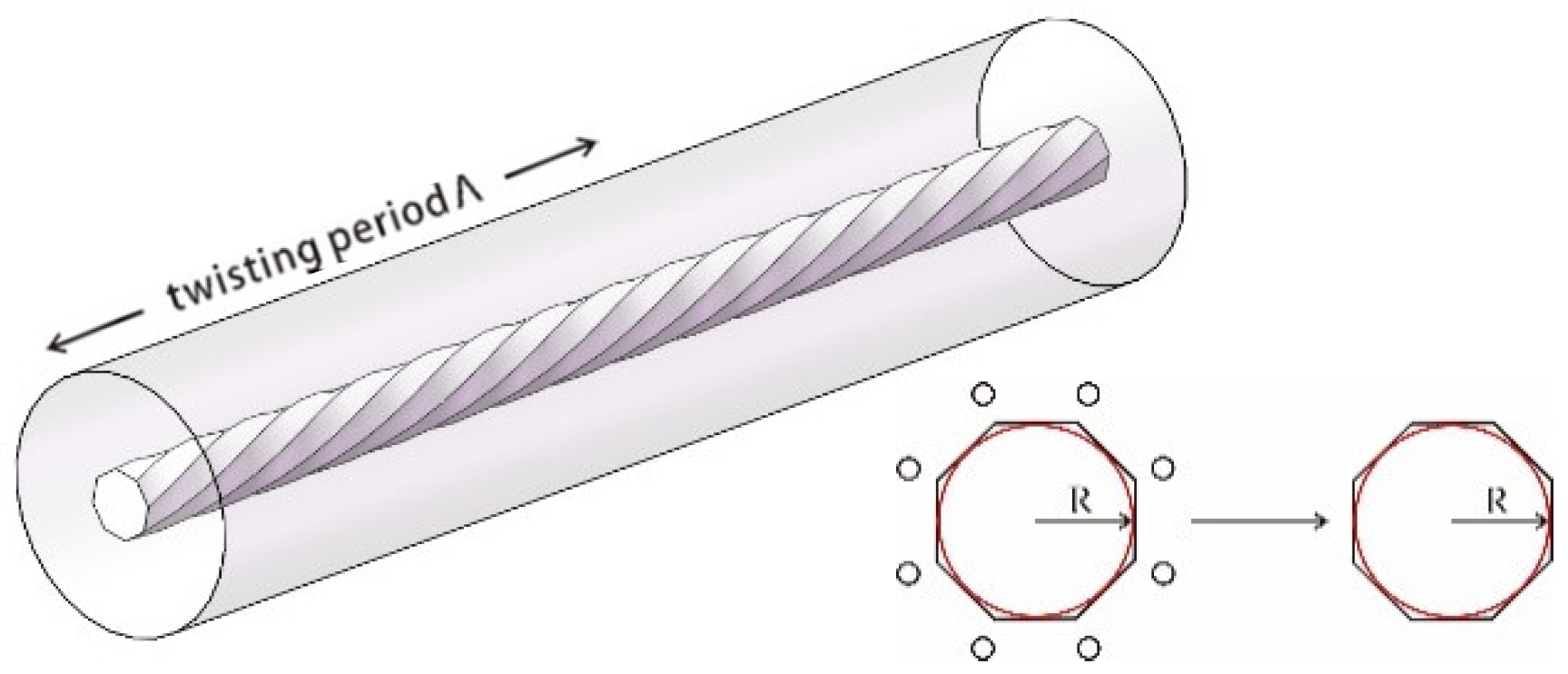
Twisted polygon-shaped core fiber is one fiber modified from P-CCC fiber with the side cores removed, as shown in Figure 2 (inset). With this removing approach, the design and fabrication complexity of the fiber will be decreased (six design parameters in P-CCC fibers to three design parameters in twisted polygon-shaped core fibers), but good single mode performance can also be maintained. Twisted polygon-shaped core fibers are based on two channels to achieve LMA SM operation. One of the two is coupling central core HOMs into central core leaky modes through quasi-phase matching between them, which has been explained in P-CCC fibers [22]. The other is fast-twisting caused propagation loss, and it can be explained as such: a polygon-shaped core causes a part of power in modes distributing around corners [30], and this power will experience fast helical propagation due to the twisted structure of the fiber core, which will cause loss of power similarly to a tight bend caused loss. In fact, all the modes in a twisted polygon-shaped core fiber suffer loss. With the coupling and fast twisting approach, twisted octagon-shaped and heptagon-shaped core fibers are designed to achieve LMA SM operation.

3.1. Twisted Octagon-Shaped Core Fiber

Figure 2 shows the twisted octagon-shaped core fiber structure and notations, where R is the inscribed circle radius and Λ is the twisting period. This fiber consists of a high refractive index octagon-shaped core twisting on the fiber axis, and a low refractive index cladding. This kind of fiber can be fabricated by spinning a fiber preform containing a polygon-shaped core during the fiber drawing process. Here, the refractive index of cladding is set to be the refractive index of silica at 1064 nm, n cl = 1.4496 , and the diameter of cladding is set to be 320 μm in all fiber designs. Numerical aperture is defined as NA   = n co 2 n cl 2 , where n co is the refractive index of the core.
As the polygon-shaped core is twisted, the modes will carry angular momentum, which will cause different increments in each modes’ propagation constant. Then, the degeneracy of the linearly polarized ( LP mn -) mode group, which constitutes linear combinations of eigenmodes ( TE 0 n modes, TM 0 n modes, HE ln and EH ln hybrid modes, where l = m ± 1 ), is broken in the twisted polygon-shaped core fibers. The effective refractive index of the mode in a twisted polygon-shaped core fiber in a helicoidal coordinate system is given by [19]:
n eff =   n eff   ±   m λ Λ
where n eff is the effective refractive index of the untwisted polygon-shaped core fiber (the same fiber design parameters, R and NA, to the twisted one) in a Cartesian coordinate system and m is the azimuthal mode number of the mode.
As there is power of modes distributing around corners of the polygon-shaped core, all modes of the core sustain loss due to the twisted structure. However, parameters (R, Λ and NA) can be chosen such that HOMs experience sufficient loss compared to FM. Losses of modes of a twisted octagon-shaped core fiber with R = 25 μm, NA = 0.065, Λ = 4.2 mm, and λ = 1064 nm are listed in Table 1. The imaginary part of effective RI ( n eff ), listed in the fourth column (untwisted) of Table 1, in the untwisted octagon-shaped core fiber design (the same fiber design parameters, R and NA, to the twisted one) are lower than 1e−19i, which are not presented. The effective RI ( n eff ), listed in the fourth column (twisted) of Table 1, in this twisted octagon-shaped core fiber calculated by FEM modal solver are consistent with the Equation (6). The FM losses lower than 0.3 dB/m and the first HOMs losses higher than 15 dB/m are achieved in this fiber design.
For fixed R = 25 μm and NA = 0.065, when Λ is in the range of 3.9–4.5 mm, sufficient first HOM suppression is ensured (>10 dB/m) and FM losses vary in the range of 0.1–0.5 dB/m. When Λ = 4.1 mm, the loss ratio between the first HOMs and FM reaches 80, as presented in Figure 3. It can be seen that the first HOM losses are significantly affected by the twisting period, and it will be demonstrated that the quasi-phase matching is the dominant mechanism for high first HOM suppression.
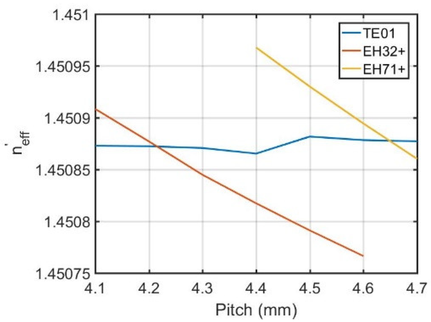
To show the modal losses caused by twisted structure in polygon-shaped core fibers, here we take HE11 and TE01 modes as an example. Intensity profiles of HE11 and TE01 modes of an untwisted octagon-shaped core fiber designs with R = 25 μm, NA = 0.065, and λ = 1064 nm are shown in Figure 4. The values (99.27%, 98.08%) are power fractions of modes (HE11 and TE01) in the inscribed circle of the octagonal shape. There is power of these modes distributing around corners of the octagonal shape, which will cause propagation loss when twisting is introduced into this octagon-shaped core fiber design. The low loss of HE11 mode is induced by this effect, and it also contributes to the high losses of HOMs. However, the high losses of HOMs come from the angular-momentum assisted quasi-phase-matching shown in Figure 5. The calculated effective index lines in the helicoidal coordinate system of TE01 and EH32+ modes intersect around Λ = 4.2 mm, and EH71+ modes intersect around Λ = 4.65 mm. The EH32+ and EH71+ modes are leaky modes at 1064 nm, which means that they exhibit high loss when propagating along the fiber. When the leaky modes couple with the first HOMs, it will cause high losses and deformation in these HOMs.
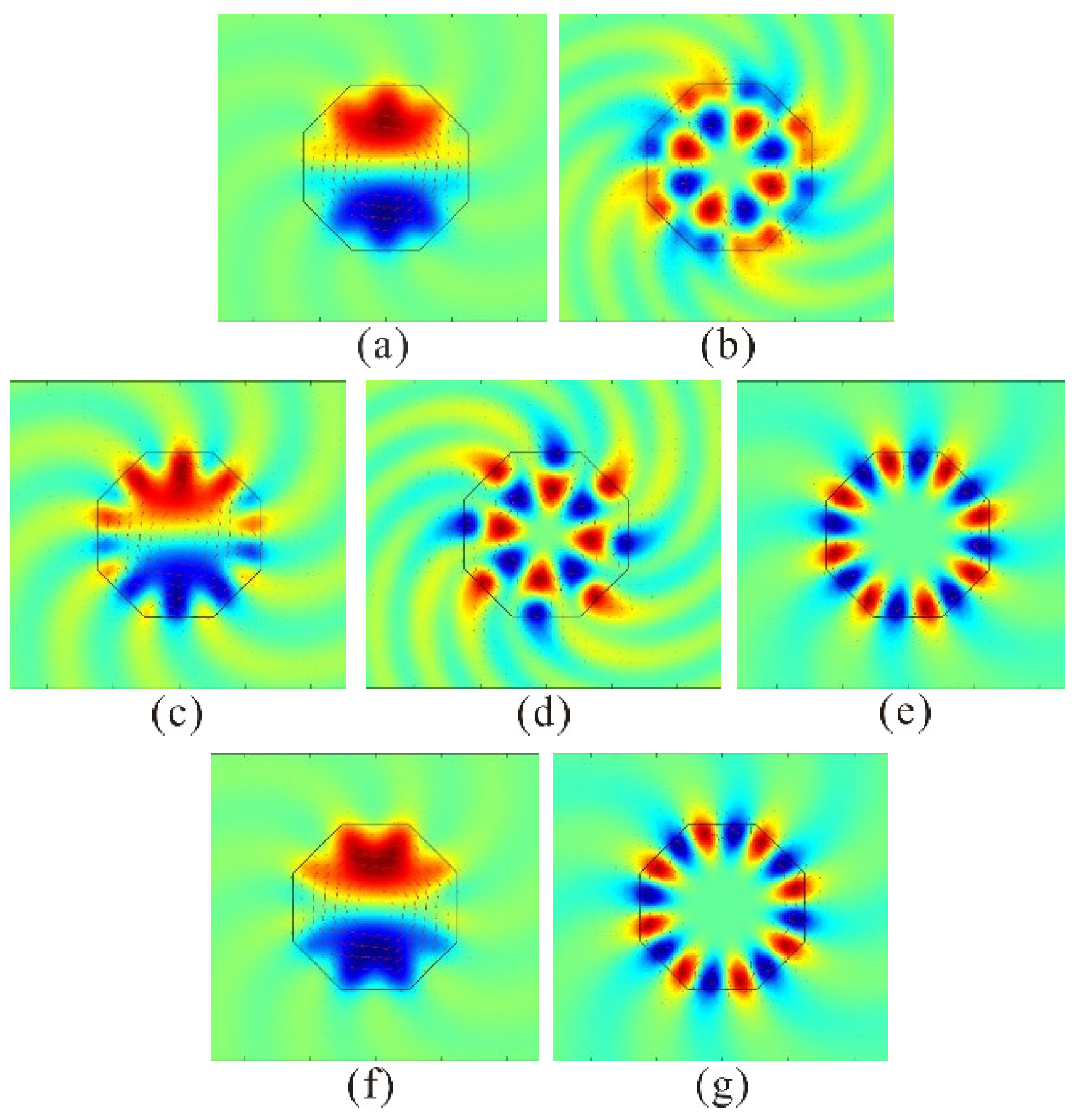
To show the modal coupling caused mode deformation of these modes, x-components (Ex) of electric field distributions of TE01, EH32+, and EH71+ modes of a twisted octagon-shaped core fiber design with R = 25 μm, NA = 0.065, λ = 1064 nm, and Λ = 4.2 mm ((a) TE01, (b) EH32+), 4.4 mm((c) TE01, (d) EH32+, (e) EH71+), 4.6 mm ((f) TE01, (g) EH71+) are shown in Figure 6. It can be seen that there is power of guided mode leaking into cladding, shown in Figure 6a,c,f. The Ex of electric field distribution of TE01 mode around the core and cladding interface changes to EH32+ and EH71+ modes, particularly when Λ = 4.4 mm. This also indicates that the guided mode TE01 couples with leaky modes EH32+ and EH71+. The tail-like profiles, which appear in TE01, EH32+, and EH71+ modes, show that these modes carry angular momentum, and electric fields distributing outside the octagon-shaped core are induced by the losses of these modes.
The relationship between the modal losses and wavelength in a twisted octagon-shaped core fiber design with R = 25 μm and NA = 0.065 is shown in Figure 7a. The losses of first HOMs remain larger than 10 dB/m when wavelength changes from 1040 nm to 1080 nm, and the losses of FM increase with the wavelength, but lower than 0.5 dB/m. Figure 7b shows the impact of NA on the performance of a twisted octagon-shaped core fiber while keeping R = 25 μm and λ = 1064 nm. For NA in the range of 0.061–0.069, first HOMs losses higher than 10 dB/m are obtained with constant Λ = 4.2 mm and FM losses keep lower than 0.5 dB/m. The largest loss ratio (>100) between the first HOMs (losses larger than 10 dB/m) and FM (lower than 0.1 dB/m) is achieved when NA = 0.069, which is a recommended criterion in fiber laser applications for SM operation [6], shown in Figure 7b.

3.2. Twisted Heptagon-Shaped Core Fiber

The mechanism to achieve single mode operation is also applicable for a modified structure, twisted heptagon-shaped core fiber, which is modified from twisted octagon-shaped core fiber with the passing from octagonal shape to heptagonal shape. Similarly, twisted structure caused modal loss will appear in twisted heptagon-shaped core fibers. FM losses lower than 0.2 dB/m and first HOM losses higher than 11 dB/m are achieved in a twisted heptagon-shaped core fiber with R = 25 μm, NA = 0.063, Λ = 4.5 mm, and λ = 1064 nm, listed in Table 2.
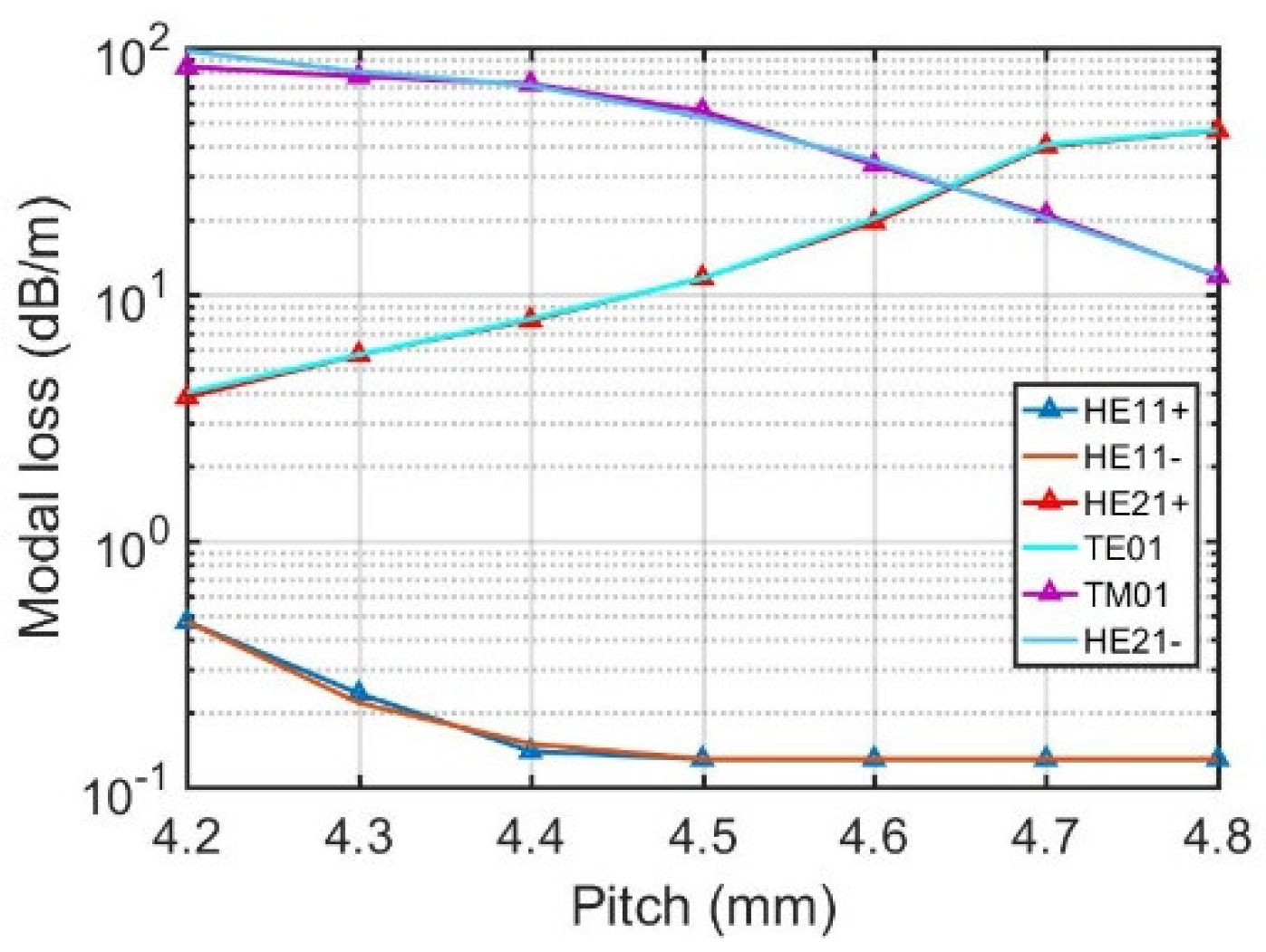
Modal losses of this fiber design in the range of 1.03–1.08 um are shown in Figure 8a. It demonstrates that over about 20 nm range from 1060 nm to 1080 nm, FM presents low losses (<0.2 dB/m) and first HOMs exhibit high losses (>10 dB/m). Figure 8b shows the modal losses of this fiber design as a function of NA. The losses of HE11+ and HE11 modes decrease to 0.01 dB/m when NA = 0.069, but the losses of HE21+ and TE01 modes also drop dramatically once NA is larger than 0.063. When R = 25 μm, λ = 1064 nm and NA is fixed at 0.063, FM losses remain lower than 0.2 dB/m while first HOM losses are higher than 10 dB/m with Λ in the range of 4.5–4.8 mm, as presented in Figure 9. The high loss ratio (>150) between first HOMs and FM is achieved with Λ in the range of 4.6–4.7 mm.

3.3. Mode Area Scaling

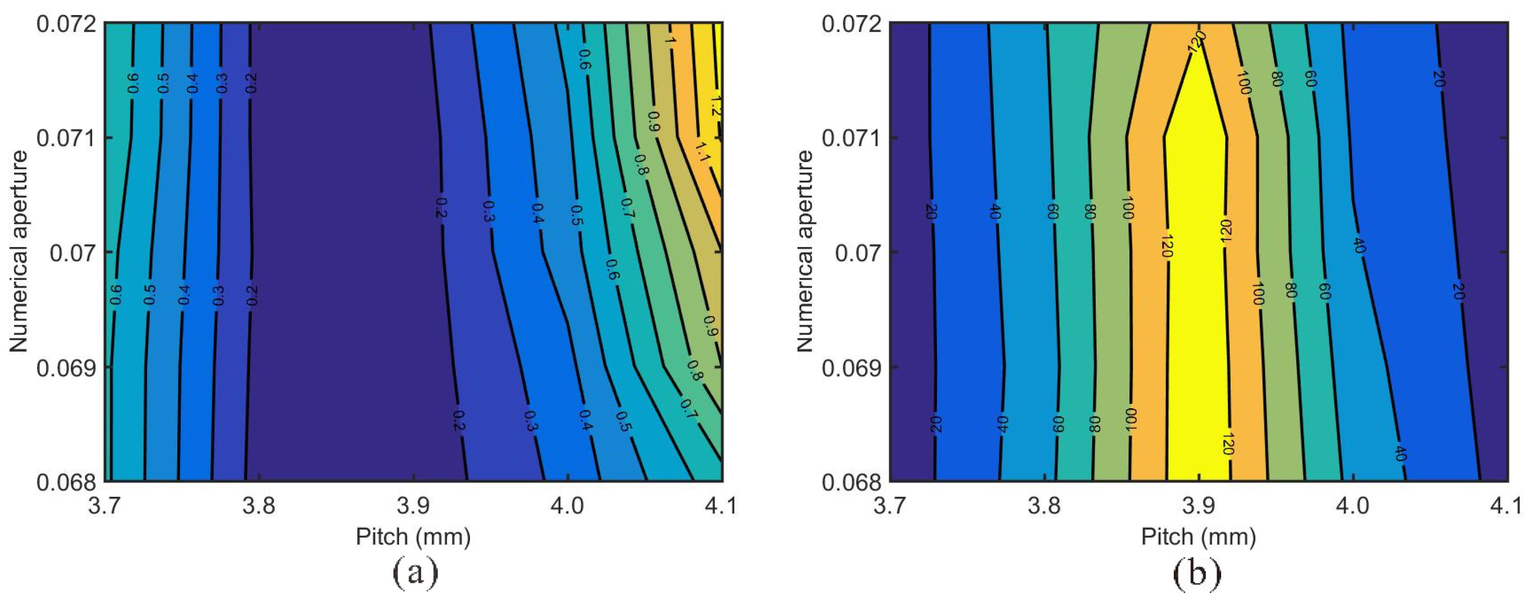
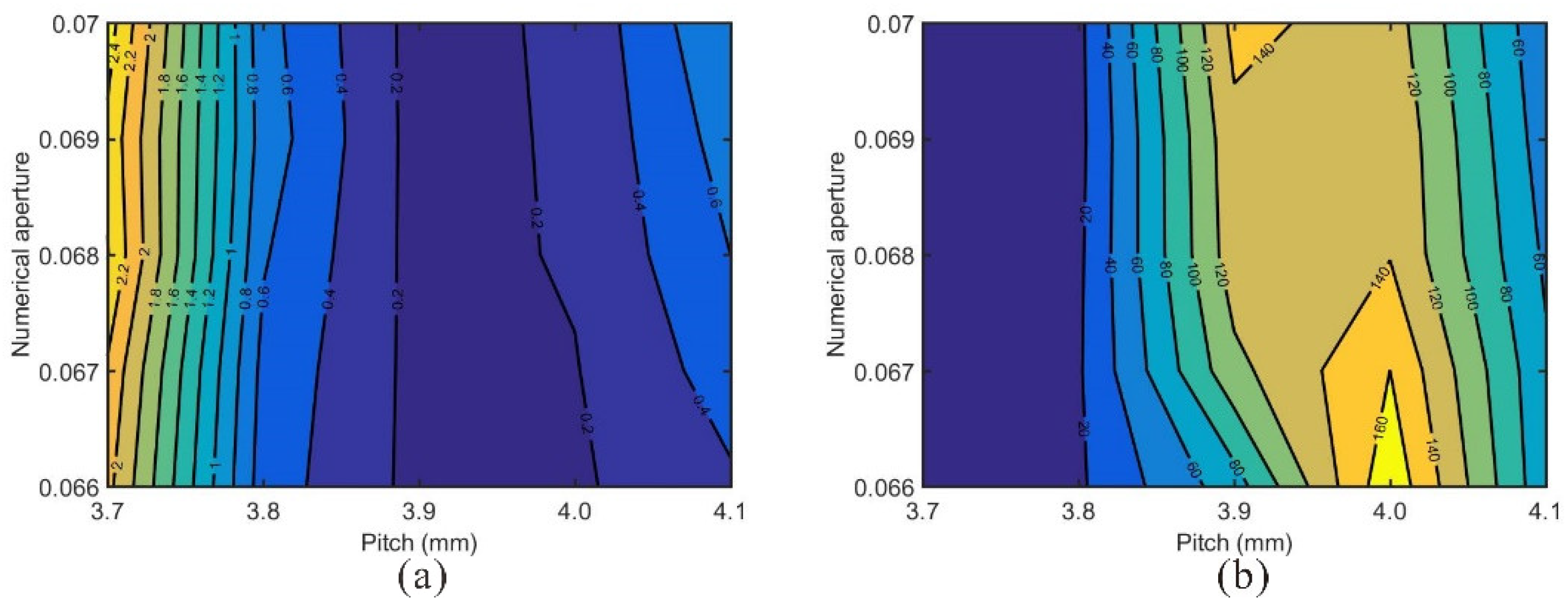
In this section, the core diameters of fibers are scaled up to 80 μm for SM operation. SM operation is achieved in a twisted octagon-shaped core fiber with R = 40 μm, NA = 0.07, and Λ = 3.9 mm, and losses of HE11+, HE11, HE21+, TE01, TM01, and HE21 modes at 1064 nm are 0.14 dB/m, 0.15 dB/m, 19.08 dB/m, 19.34 dB/m, 35.24 dB/m, and 33.65 dB/m, respectively. The FM losses of this fiber with different combinations of NA (in the range of 0.068–0.072) and Λ (in the range of 3.7–4.1 mm) and ratios of the lower one of first HOM losses to fundamental mode losses are shown in Figure 10a and Figure 10b, respectively. In these combinations, the FM losses vary from lower than 0.2 dB/m to 1.2 dB/m, while the loss ratio varies from lower than 20 to higher than 120. In a twisted heptagon-shaped core fiber with R = 40 μm, NA = 0.068, Λ = 3.9 mm, losses of HE11+, HE11, HE21+, TE01, TM01, and HE21 modes at 1064 nm are 0.14 dB/m, 0.13 dB/m, 17.08 dB/m, 17.49 dB/m, 93.35 dB/m, and 92.33 dB/m, respectively. For the combinations of NA (in the range of 0.066–0.07) and Λ (in the range of 3.7–4.1 mm), FM losses vary from lower than 0.2 dB/m to 2.4 dB/m, and the ratio of the lower one of first HOM losses to FM losses exceeds 160 when NA = 0.066 and Λ = 4 mm, shown in Figure 11a,b, respectively.
As modal overlap between guided and leaky modes also appears in a larger core size, with appropriate design parameters, the core diameter may be further increased due to the origin of the modal loss coming from the twisting-caused loss and quasi-phase matching between HOMs and leaky modes.

3.4. Discussion

Numerical results show that it is possible to achieve single mode operation in a large mode area twisted polygon-shaped core fiber. Twisting-induced high losses to higher order modes and coupling higher order modes with leaky modes play a significant role in efficient higher order mode discrimination. Twisted polygon-shaped core fibers not only noticeably decrease the design and fabrication complexity in P-CCC fiber but also demonstrate the feasibility of extending the octagon-shaped core, a central core of P-CCC fiber, to heptagon-shaped or other polygon-shaped core for a single mode LMA fiber. The modal overlap between HOMs and leaky modes does not decline with the core size, which allows significantly increasing core size of twisted polygon-shaped core fibers [22].

4. Conclusions

In this paper, we propose all solid twisted polygon-shaped core fibers for SM operation with large mode areas. SM operation is ensured by coupling HOMs with leaky modes and twisting-caused loss. It demonstrates that a fiber can achieve SM operation with only a twisted polygon-shaped core, which is not the case in P-CCC fiber that both the eight-side cores and polygon-shaped cores are indispensable. The design and fabrication complexity is reduced in this fiber design compared to P-CCC fiber. A twisted octagon-shaped core fiber with core size of 50 μm (NA = 0.065, Λ = 4.2 mm, and λ = 1064 nm) can achieve low FM losses, 0.3 dB/m, and high first HOM suppression, >15 dB/m. The core diameter can be further scaled up to 80 μm (NA = 0.07, Λ = 3.9 mm, and λ = 1064 nm) with FM losses lower than 0.15 dB/m and first HOM losses higher than 19 dB/m. Twisted heptagon-shaped core fiber can obtain FM losses lower than 0.2 dB/m and first HOM losses higher than 11 dB/m with a core diameter of 50 μm (NA = 0.063, Λ = 4.5 mm, and λ = 1064 nm), and the core diameter can be further increased to 80 μm (NA = 0.068, Λ = 3.9 mm, and λ = 1064 nm) with FM losses lower than 0.14 dB/m and first HOM losses higher than 17 dB/m. It is worth noting that the mechanism by which to achieve single mode operation in twisted octagonal- and heptagonal-shaped core fibers is also applicable to twisted structures with other polygon-shaped cores.

Author Contributions

Conceptualization, K.S. and S.Z.; investigation, K.S., S.Z. and L.L.; data curation, L.L.; writing—original draft preparation, K.S.; writing—review and editing, C.H. and X.M.; supervision, X.M.; funding acquisition, X.M. All authors have read and agreed to the published version of the manuscript.

Funding

This research was funded by National Natural Science Foundation of China (NSFC), grant number 81927805, Guangdong Major Project of Basic and Applied Basic Research, grant number 2019B030302003, and Science and Technology Planning Project of Guangdong Province, grant number 2018B090944001.

Data Availability Statement

All relevant data are available from the authors upon reasonable request.

Conflicts of Interest

The authors declare no conflict of interest.

References

  1. Dawson, J.W.; Messerly, M.J.; Beach, R.J.; Shverdin, M.Y.; Stappaerts, A.; Sridharan, A.K.; Pax, P.H.; Heebner, J.E.; Siders, C.W.; Barty, C.P.J. Analysis of the Scalability of Diffraction-Limited Fiber Lasers and Amplifiers to High Average Power. Opt. Express 2008, 16, 13240–13266. [Google Scholar] [CrossRef] [PubMed]
  2. Shi, W.; Fang, Q.; Zhu, X.; Norwood, R.A.; Peyghambarian, N. Fiber Lasers and Their Applications [Invited]. Appl. Opt. 2014, 53, 6554–6568. [Google Scholar] [CrossRef] [PubMed]
  3. Gapontsev, V.; Avdokhin, A.; Kadwani, P.; Samartsev, I.; Platonov, N.; Yagodkin, R. SM Green Fiber Laser Operating in CW and QCW Regimes and Producing over 550W of Average Output Power. In Nonlinear Frequency Generation and Conversion: Materials, Devices, and Applications XIII; SPIE: Bellingham, WA, USA, 2014; Volume 8964, pp. 36–44. [Google Scholar]
  4. Liu, Z.; Ma, P.; Su, R.; Tao, R.; Ma, Y.; Wang, X.; Zhou, P. High-Power Coherent Beam Polarization Combination of Fiber Lasers: Progress and Prospect [Invited]. J. Opt. Soc. Am. B 2017, 34, A7–A14. [Google Scholar] [CrossRef]
  5. Buikema, A.; Jose, F.; Augst, S.J.; Fritschel, P.; Mavalvala, N. Narrow-Linewidth Fiber Amplifier for Gravitational-Wave Detectors. Opt. Lett. 2019, 44, 3833–3836. [Google Scholar] [CrossRef] [PubMed]
  6. Li, M.J.; Chen, X.; Liu, A.; Gray, S.; Wang, J.; Walton, D.T.; Zenteno, L.A. Limit of Effective Area for Single-Mode Operation in Step-Index Large Mode Area Laser Fibers. J. Lightwave Technol. 2009, 27, 3010–3016. [Google Scholar]
  7. Jain, D.; Jung, Y.; Barua, P.; Alam, S.; Sahu, J.K. Demonstration of Ultra-Low NA Rare-Earth Doped Step Index Fiber for Applications in High Power Fiber Lasers. Opt. Express 2015, 23, 7407–7415. [Google Scholar] [CrossRef] [PubMed] [Green Version]
  8. Franczyk, M.; Stawicki, K.; Lisowska, J.; Michalik, D.; Filipkowski, A.; Buczynski, R. Numerical Studies on Large-Mode Area Fibers with Nanostructured Core for Fiber Lasers. J. Lightwave Technol. 2018, 36, 5334–5343. [Google Scholar] [CrossRef]
  9. Franczyk, M.; Pysz, D.; Pucko, P.; Michalik, D.; Biduś, M.; Dłubek, M.; Buczyński, R. Yb3+ Doped Silica Nanostructured Core Fiber Laser. Opt. Express 2019, 27, 35108–35119. [Google Scholar] [CrossRef]
  10. Limpert, J.; Liem, A.; Reich, M.; Schreiber, T.; Nolte, S.; Zellmer, H.; Tünnermann, A.; Broeng, J.; Petersson, A.; Jakobsen, C. Low-Nonlinearity Single-Transverse-Mode Ytterbium-Doped Photonic Crystal Fiber Amplifier. Opt. Express 2004, 12, 1313–1319. [Google Scholar] [CrossRef]
  11. Huang, L.; Kong, L.; Leng, J.; Zhou, P.; Guo, S.; Cheng, X. Impact of High-Order-Mode Loss on High-Power Fiber Amplifiers. J. Opt. Soc. Am. B 2016, 33, 1030–1037. [Google Scholar] [CrossRef]
  12. Koplow, J.P.; Kliner, D.A.V.; Goldberg, L. Single-Mode Operation of a Coiled Multimode Fiber Amplifier. Opt. Lett. 2000, 25, 442–444. [Google Scholar] [CrossRef] [PubMed] [Green Version]
  13. Jain, D.; Jung, Y.; Nunez-Velazquez, M.; Sahu, J.K. Extending Single Mode Performance of All-Solid Large-Mode-Area Single Trench Fiber. Opt. Express 2014, 22, 31078–31091. [Google Scholar] [CrossRef] [PubMed] [Green Version]
  14. Jain, D.; Baskiotis, C.; Sahu, J.K. Mode Area Scaling with Multi-Trench Rod-Type Fibers. Opt. Express 2013, 21, 1448–1455. [Google Scholar] [CrossRef] [PubMed]
  15. Jain, D.; Alam, S.; Codemard, C.; Jung, Y.; Zervas, M.N.; Sahu, J.K. High Power, Compact, Picosecond MOPA Based on Single Trench Fiber with Single Polarized Diffraction-Limited Output. Opt. Lett. 2015, 40, 4150–4153. [Google Scholar] [CrossRef] [PubMed]
  16. Kashiwagi, M.; Saitoh, K.; Takenaga, K.; Tanigawa, S.; Matsuo, S.; Fujimaki, M. Effectively Single-Mode All-Solid Photonic Bandgap Fiber with Large Effective Area and Low Bending Loss for Compact High-Power All-Fiber Lasers. Opt. Express 2012, 20, 15061–15070. [Google Scholar] [CrossRef]
  17. Fermann, M.E. Single-Mode Excitation of Multimode Fibers with Ultrashort Pulses. Opt. Lett. 1998, 23, 52–54. [Google Scholar] [CrossRef] [PubMed]
  18. Nicholson, J.W.; DeSantolo, A.; Westbrook, P.S.; Windeler, R.S.; Kremp, T.; Headley, C.; DiGiovanni, D.J. Axicons for Mode Conversion in High Peak Power, Higher-Order Mode, Fiber Amplifiers. Opt. Express 2015, 23, 33849–33860. [Google Scholar] [CrossRef]
  19. Wang, X.; Chen, Y.; Hageman, W.; Kim, G.U.; Richardson, M.; Xiong, C.; Ballato, J.; Bass, M. Transverse Mode Competition in Gain-Guided Index Antiguided Fiber Lasers. J. Opt. Soc. Am. B 2012, 29, 191–196. [Google Scholar] [CrossRef]
  20. Edavalath, N.N.; Günendi, M.C.; Beravat, R.; Wong, G.K.L.; Frosz, M.H.; Ménard, J.-M.; Russell, P.S.J. Higher-Order Mode Suppression in Twisted Single-Ring Hollow-Core Photonic Crystal Fibers. Opt. Lett. 2017, 42, 2074–2077. [Google Scholar] [CrossRef]
  21. Ma, X.; Liu, C.; Chang, G.; Galvanauskas, A. Angular-Momentum Coupled Optical Waves in Chirally-Coupled-Core Fibers. Opt. Express 2011, 19, 2252–2258. [Google Scholar] [CrossRef]
  22. Ma, X.; Zhu, C.; Hu, I.-N.; Kaplan, A.; Galvanauskas, A. Single-Mode Chirally-Coupled-Core Fibers with Larger than 50µm Diameter Cores. Opt. Express 2014, 22, 9206–9219. [Google Scholar] [CrossRef] [PubMed]
  23. Napiorkowski, M.; Urbanczyk, W. Rigorous Simulations of Coupling between Core and Cladding Modes in a Double-Helix Fiber. Opt. Lett. 2015, 40, 3324–3327. [Google Scholar] [CrossRef] [PubMed]
  24. Shen, X.; Yang, Z.; Xi, X.; Zhang, Z.; Wei, W. Numerical Investigation for the Mode Transmission Characteristics of a Large Mode Area Optical Fiber with Heterogeneous Helical Claddings Designed for 2.0μm. Opt. Lett. 2021, 46, 4342–4345. [Google Scholar] [CrossRef] [PubMed]
  25. Napiorkowski, M.; Urbanczyk, W. Rigorous Modeling of Twisted Anisotropic Optical Fibers with Transformation Optics Formalism. Opt. Express 2021, 29, 15199–15216. [Google Scholar] [CrossRef] [PubMed]
  26. Napiorkowski, M.; Urbanczyk, W. Role of Symmetry in Mode Coupling in Twisted Microstructured Optical Fibers. Opt. Lett. 2018, 43, 395–398. [Google Scholar] [CrossRef]
  27. Nicolet, A.; Zolla, F.; Guenneau, S. Modelling of twisted optical waveguides with edge elements. Eur. Phys. J. Appl. Phys. 2004, 28, 153–157. [Google Scholar] [CrossRef]
  28. Napiorkowski, M.; Urbanczyk, W. Rigorous Simulations of a Helical Core Fiber by the Use of Transformation Optics Formalism. Opt. Express 2014, 22, 23108–23120. [Google Scholar] [CrossRef]
  29. Han, J.; Liu, E.; Liu, J. Circular gradient-diameter photonic crystal fiber with large mode area and low bending loss. J. Opt. Soc. Am. A 2019, 36, 533–539. [Google Scholar] [CrossRef]
  30. Wang, Y.; Liao, L.; Zhao, N.; Dai, N.; Li, H.; Peng, J.; Li, J. A New Type of Yb3+ Doped Fiber with an Octagonal-Shaped Core. In Proceedings of the 2015 Conference on Lasers and Electro-Optics (CLEO), San Jose, CA, USA, 10–15 August 2015. [Google Scholar]
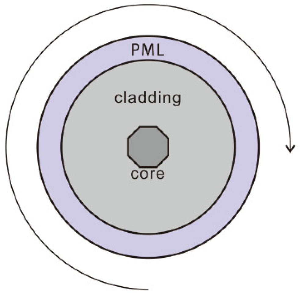
Figure 1. FEM model of the twisted polygon-shaped (octagon) core fiber. The round arrow indicates the twisting direction.
Photonics 09 00221 g001
Figure 2. Twisted octagon-shaped core fiber structure. Inset image shows the modification from a P-CCC fiber to a twisted octagon-shaped core fiber (cross section), and the red line is the inscribed circle of the octagonal shape. R is the inscribed circle radius and Λ is the twisting period.
Photonics 09 00221 g002
Figure 3. Modal losses of a twisted octagon-shaped core fiber versus Λ with R = 25 μm, NA = 0.065, and λ = 1064 nm, Λ in the range of 3.9–4.5 mm.
Photonics 09 00221 g003
Figure 4. Intensity profiles of HE11 (left) and TE01 (right) modes in an untwisted octagon-shaped core fiber with R = 25 μm, NA = 0.065 and λ = 1064 nm.
Photonics 09 00221 g004
Figure 5. Modal coupling between a guided mode TE01 and leaky modes EH32+ and EH71+ in a twisted octagon-shaped core fiber with R = 25 μm, NA = 0.065, λ = 1064 nm, and Λ in the range of 4.1–4.7 mm.
Photonics 09 00221 g005
Figure 6. X-components (Ex) of electric field distributions of a guided mode TE01 and leaky modes EH32+ and EH71+ in a twisted octagon-shaped core fiber with R = 25 μm, NA = 0.065, λ = 1064 nm, and Λ = 4.2 mm ((a) TE01, (b) EH32+), 4.4 mm ((c) TE01, (d) EH32+, (e) EH71+), 4.6 mm ((f) TE01, (g) EH71+).
Photonics 09 00221 g006
Figure 7. (a) Modal losses of a twisted octagon-shaped core fiber versus wavelength with R = 25 μm, Λ = 4.2 mm, and NA = 0.065, λ in the range of 1.03–1.08 μm. (b) Modal losses of a twisted octagon-shaped core fiber versus NA with R = 25 μm, Λ = 4.2 mm, and λ = 1064 nm, NA in the range of 0.061–0.069.
Photonics 09 00221 g007
Figure 8. (a) Modal losses of a twisted heptagon-shaped core fiber versus wavelength with R = 25 μm, Λ = 4.5 mm, and NA = 0.063, λ in the range of 1.03–1.08 μm. (b) Modal losses of a twisted heptagon-shaped core fiber versus NA with R = 25 μm, Λ = 4.5 mm, and λ = 1064 nm, NA in the range of 0.061–0.069.
Photonics 09 00221 g008
Figure 9. Modal losses of a twisted heptagon-shaped core fiber versus Λ with R = 25 μm, NA = 0.065, and λ = 1064 nm, Λ in the range of 4.2–4.8 mm.
Photonics 09 00221 g009
Figure 10. (a) Modal losses of FM in a twisted octagon-shaped core fiber versus Λ and NA with R = 40 μm, λ = 1064 nm, NA in the range of 0.068–0.072, and Λ in the range of 3.7–4.1 mm. (b) Ratios of the lower one of first HOM losses to fundamental mode losses.
Photonics 09 00221 g010
Figure 11. (a) Modal losses of FM in a twisted heptagon-shaped core fiber versus Λ and NA with R = 40 μm, λ = 1064 nm, NA in the range of 0.066–0.07, and Λ in the range of 3.7–4.1 mm. (b) Ratios of the lower one of first HOM losses to fundamental mode losses.
Photonics 09 00221 g011
Table 1. Degeneracy breaking of the linearly polarized LPmn mode group, increment of the effective RI from an untwisted ( n eff ) to twisted ( n eff ) fiber, and modal losses of a twisted octagon-shaped core fiber with R = 25 μm, NA = 0.065, Λ = 4.2 mm, and λ = 1064 nm.
LP ModesModes in Helicoidal CoordinatesAzimuthal Mode NumberEffective RI (Untwisted→Twisted)Modal Loss in dB/m
LP01HE11+11.450985→1.451238−5.605259e−9i0.29
HE1111.450985→1.450731−5.413734e−9i0.28
LP11HE21+21.450875→1.451379−4.381172e−7i22.47
TE0101.450875→1.450872−4.441430e−7i22.77
TM0101.450875→1.450875−3.133396e−7i16.05
HE2121.450875→1.450369−3.110502e−7i15.95
Table 2. Degeneracy breaking of a linearly polarized LPmn mode group, increment of the effective RI from untwisted ( n eff ) to twisted ( n eff ) fiber, and modal losses of a twisted heptagon-shaped core fiber with R = 25 μm, NA = 0.063, Λ = 4.5 mm, and λ = 1064 nm.
LP ModesModes in Helicoidal CoordinatesAzimuthal Mode NumberEffective RI (Untwisted→Twisted)Modal Loss in dB/m
LP01HE11+11.450898→1.451134−2.510708e−9i0.13
HE1111.450898→1.450661−2.462778e−9i0.13
LP11HE21+21.450790→1.451259−2.266232e−7i 11.64
TE0101.450790→1.450786−2.256496e−7i11.59
TM0101.450790→1.450791−1.083072e−6i 55.40
HE2121.450790→1.450318−1.022606e−6i52.32
Publisher’s Note: MDPI stays neutral with regard to jurisdictional claims in published maps and institutional affiliations.