Article

A CMOS-Compatible Carrier-Injection Plasmonic Micro-Ring Modulator with Resonance Tuning by Carrier Concentration

1
Institute of Microelectronics, Chinese Academy of Sciences, Beijing 100029, China
2
School of Electronic Electrical and Communication Engineering, University of Chinese Academy of Sciences, Beijing 100049, China
*
Author to whom correspondence should be addressed.
Photonics 2022, 9(5), 272; https://doi.org/10.3390/photonics9050272
Submission received: 15 March 2022 / Revised: 13 April 2022 / Accepted: 13 April 2022 / Published: 19 April 2022
(This article belongs to the Topic Optical and Optoelectronic Materials and Applications)

Abstract

:
A complementary metal-oxide-semiconductor (CMOS)-compatible carrier-injection plasmonic micro-ring modulator (CIPMRM) is designed and analyzed theoretically. The CIPMRM has a compacted footprint of 49.3 μm2 (R = 2 μm), a bit rate of 36.5 Gbps, insertion loss of −9.8 dB, a static extinction ratio of 21.7 dB, and energy consumption of 4.40 pJ/bit as 2.2 V peak-to-peak voltage is applied at 1550 nm. Besides, the method of resonance tuning by carrier concentration is proposed to compensate for the wavelength mismatch between the CIPMRM resonance and the laser, resulting from temperature and line width variation of the CIPMRM. This method has a faster response time and a greater ability to shift the resonant wavelength compared with the method of thermo-optic resonance tuning. The proposed scheme provides a route for realizing the compacted size modulator for optoelectronic integration.

1. Introduction

Over the past decade, there has been an increasing desire to realize nanophotonic devices, which are convenient for optoelectronic integration because of their high integration. Plasmonics is a promising approach to achieve nanophotonic devices, and it can be utilized to merge the photonic and nanoelectronic devices. The plasmonics is a surface electromagnetic wave formed by free-electron oscillation of metal when inspired by light. It has two properties that can be used to design the device. The plasmonics can break the diffraction limit as the light guild at sub-wavelength scale, which is utilized for designing nanophotonic devices. Besides, the evanescent wave caused by electron oscillations leads to a strong electromagnetic field at the surface of the metal, which enhances light–matter interaction [1,2]. Therefore, research on plasmonics has been a flourishing field, including various passive and active devices [3,4,5,6]. Among them, plasmonic modulators would be highly desirable for shortening the shift length from a millimeter to a few microns.
Several active materials are utilized in plasmonic modulators, including transparent conductive oxides (TCO), electro-optic polymers, and graphene. As a metal-insulator-oxide layer (MIS) architecture is used, the permittivity of TCOs can be tuned by changing the carrier density near the insulator layer. Due to the strong surface field of the plasmonic wave, the shift length reduces to a few microns [7]. Various theoretical investigations predict its bandwidth to be tens of GHz. However, the bandwidth of the plasmonic modulator with TCO hardly exceeds 3 GHz at present [8,9,10,11,12]. Plasmonic modulators with electro-optic polymers based on the Pockels effects in nonlinear polymer have developed rapidly in recent years. Plasmonic Mach–Zehnder modulators and plasmonic micro-ring modulators with electro-optic polymers operating at over 100 GHz are realized [13,14]. The plasmonic modulator with graphene is another method for wavelength modulation, which is realized by tuning the Fermi level with gate voltage. It would have high-speed modulation for its high carrier mobility with a compacted size [15,16,17]. Although these three kinds of plasmonic modulators have an excellent performance, they are not fully compatible with the standard CMOS process. As a result, these may impede integration with electronic devices. Plasmonic modulators based on silicon are also investigated. However, the bandwidth is limited to 3 GHz [18,19]. Therefore, it is still a challenge to achieve zero-change CMOS-compatible plasmonic modulators with compact size and outstanding performance.
Silicon is the preferred CMOS-compatible material to change the refractive index by manipulating carrier density (free carrier dispersion effect) [20]. Silicon-based carrier-injection modulators are first proposed. Due to the limiting mode, the early carrier-injection modulators present poor bandwidth and energy consumption [21]. Later, silicon-on-insulator (SOI) substrates used in silicon photonics improve the performance of the modulators. A carrier-injection plasmonic micro-ring modulator (CIPMRM) is proposed and investigated theoretically in this work. Mode is limited further by plasmonic architecture to improve the modulator performance. Besides, a method of resonance tuning by injected carrier concentration is proposed to solve the resonance shift caused by temperature fluctuation and manufacturing deviation. Compared with the method of thermo-optic resonance tuning [22], it has faster responsiveness and better tuning ability. Meanwhile, this method avoids local high temperature from heating resistance. Therefore, the size of CIPMRM would not limit the free spectrum range (FSR) and the local temperature. CIPMRM provides a way to overcome the shortcomings of micro-ring modulators (MRMs). Besides, CIPMRM is a zero-change CMOS fabrication process. It has a compact footprint of 49.3 μm2, a bit rate of 36.5 Gbps, insertion loss (IL) of −9.8 dB, static extinction ratio (ER) of 21.7 dB, and energy consumption of 4.40 pJ/bit as 2.2 V peak-to-peak voltage is applied.
The remainder of this paper is organized as follows. In Section 2, the structure and physical mechanism of CIPMRMs are presented. Section 3 discusses the effects of modulation width on the performance of the CIPMRMs. Section 4 proposes the method of resonance tuning by carrier concentration as temperature and line width change. Finally, the key findings are discussed and summarized in Section 5.

2. The Structure and Operating Principle of CIPMRM

The silicon waveguide mode couples to the CIPMRM eventually. To increase the coupling efficiency, the mode of silicon waveguide couples to the near silicon waveguide first and then tapers into the CIPMRM by plasmonic taper (IL is about 1 dB). Coupling efficiency reaches 90% as the coupling distance is 160 nm and the coupling length is 3.5 μm (3D-FDTD simulated, where the PML is adopted as the boundary condition). A 340 nm SOI substrate is utilized in this work, and the width of the silicon waveguide is 300 nm. Figure 1 shows the structure of the plasmonic modulator. It is a ridge waveguide with a 100 nm slab height. A 5 nm oxide layer and a 100 nm copper layer cover the ridge that forms the plasmonic waveguide. The plasmonic is inspired by transverse electric (TE) mode. The distance between the electrodes grown on the slab and the ridge is 1μm. A highly doped concentration of 5 × 10²⁰/cm3 in P++ and N++ is used to form a PIN junction.
The free carrier dispersion effect causes the effective refractive index to change as the forward voltage is applied at the PIN junction. By altering the effective refractive index of the waveguide, the wavelength of 1550 nm will be on and off the resonant state. Eventually, it transforms the electronic signal into an optical signal. The Lumerical commercial software is used in this work. The complex refractive indices of Cu, SiO2, and Si at 1550 nm are set as follows: Cu: 0.282 + 11.048 [23], SiO2: 1.445, and Si: 3.46.

3. Carrier-Injection Plasmonic Micro-Ring Modulator

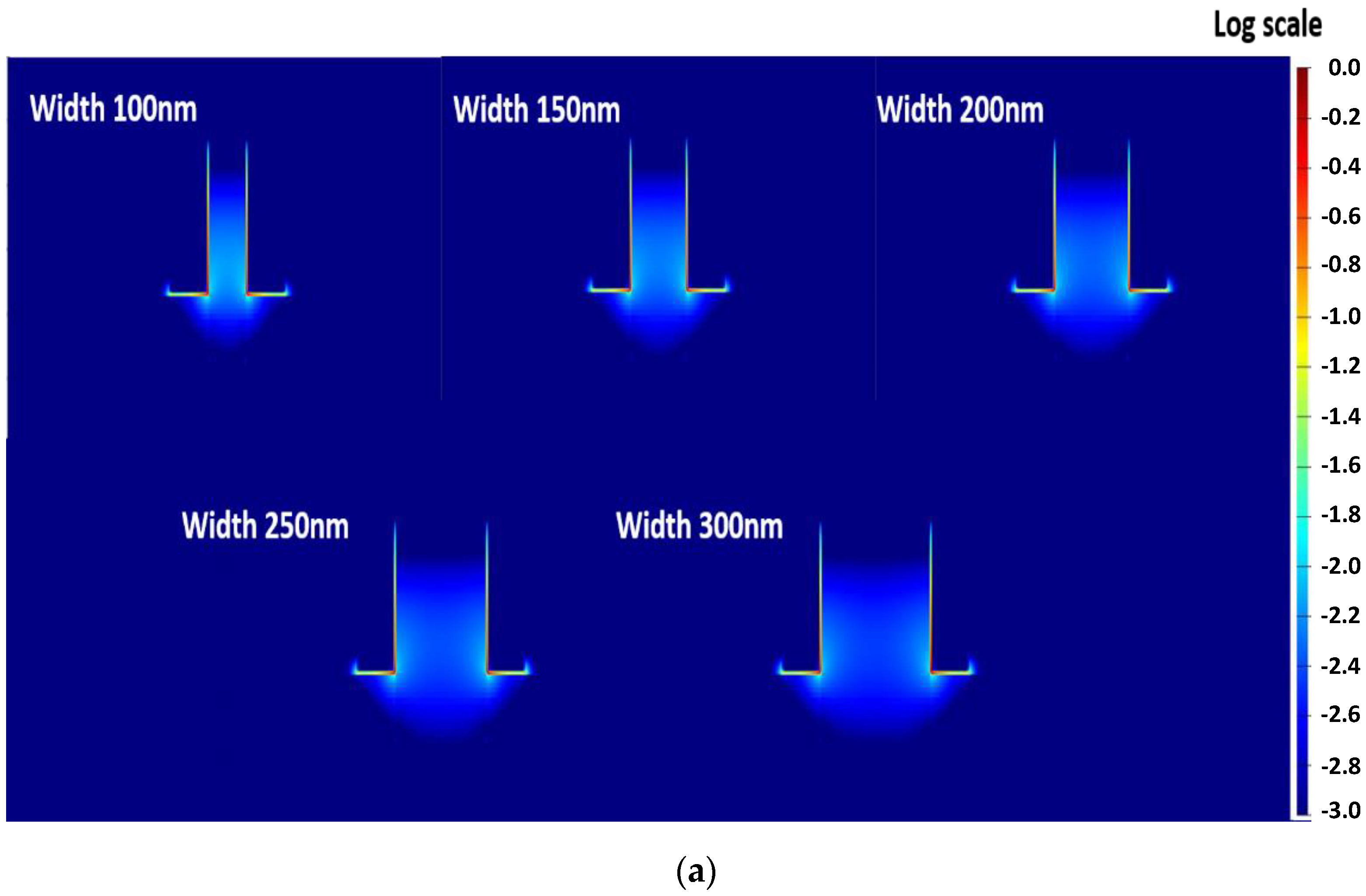
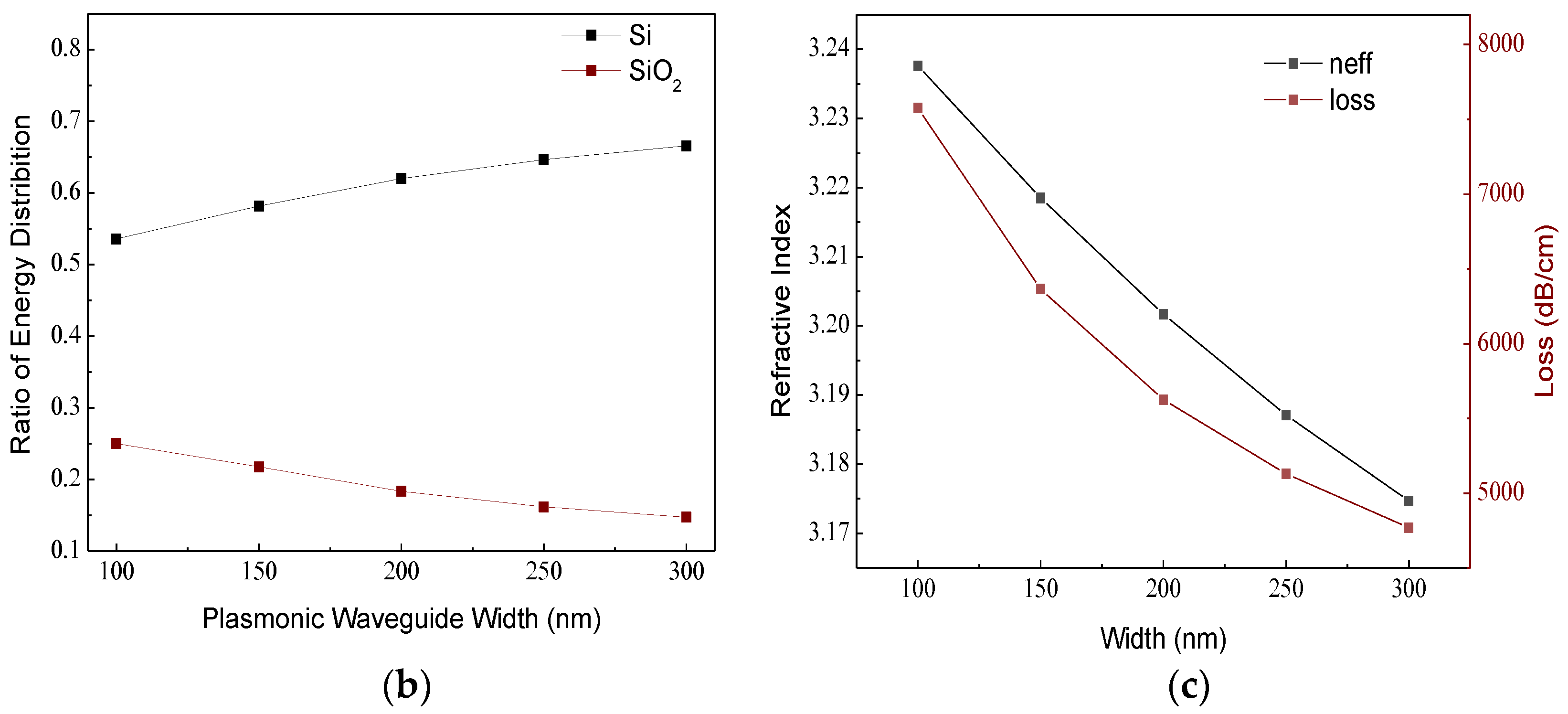
Figure 2a presents the normalized electric field distribution in a plasmonic waveguide. It can be seen that as the width of the plasmonic waveguide increases, more electric field distributes in silicon. The energy distribution ratio is shown in Figure 2b.
As the width of the plasmonic waveguide increases from 100 nm to 300 nm, the ratio of the normalized energy distribution in silicon increases from 53.6% to 66.6%, and the ratio of the normalized energy distribution in SiO2 decreases from 25% to 14.7%. Therefore, the plasmonic waveguide loss decreases from 0.75 dB/μm to 0.47 dB/μm as the width increases from 100 nm to 300 nm (shown in Figure 2c). As the plasmonic waveguide is widened, the refractive index decreases from 3.23 to 3.18. The decreasing refractive index results from the lower impact of the plasmonic metal.
Soref realized the silicon modulators by injecting a carrier as the forward voltage at the PIN junction. The little difference in the refractive index between the silicon and highly doped silicon induces the large mode, which causes poor modulation speed and high energy consumption. SOI substrates result in a significant improvement in the performance of the modulators for limiting the mode field. Here, the plasmonic waveguides further limit the mode. The effect of mode size (plasmonic waveguide width) on modulators is discussed in the following section.
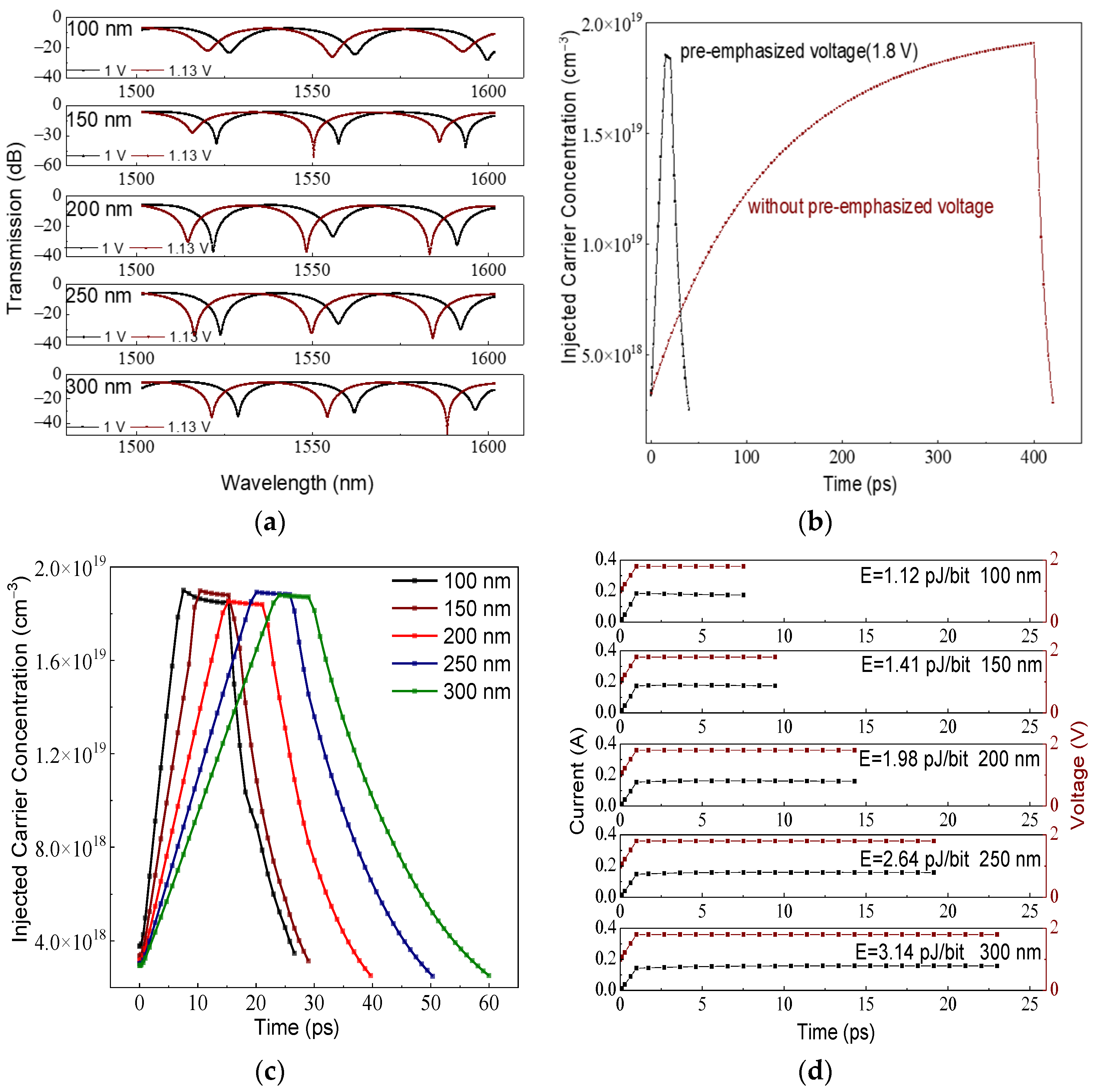
Figure 3a displays the transmission curve with wavelength for different widths of CIPMRMs at 1 V (“off-state”) and 1.13 V (“on-state”). The resonant peaks shift as the refractive index changes, which is caused by the variation in the modulator width. The minimum transmission value is achieved as the energy coupled in CIPMRMs is close to the loss there. Therefore, the transmission increases from −34.65 dB to −21.9 dB when the waveguide loss decreases from 0.76 dB/μm to 0.47 dB/μm. The decreasing waveguide loss results from the waveguide width increases. The insertion loss of CIPMRMs decreases from −11.5 dB to −9.3 dB as the modulation width increases from 100 nm to 300 nm. This situation results from two reasons. Low-loss plasmonic micro-rings benefit from modulating for their high quality factor. Besides, the resonant wavelength shifts further for the widened CIPMRMs. Because the carrier concentration is mostly the same at 1.13 V (1.9 × 10¹⁹ /cm3), more energy is distributed in the modulation region, which would boost the effects of the injected carrier on the mode.
Pre-emphasized voltage is a conventional measure for reducing the drifting time. To explain the effects of the pre-emphasized voltage, the curve of the carrier concentration with time is shown in Figure 3b for different voltage conditions. It can be seen that the rise time decreases from 400 ps to 15 ps as the 1.8 V pre-emphasized voltage is applied. The fall time of both is 18 ps. The relation curve of injected carrier concentration with time is approximated by a similar straight line when the pre-emphasized voltage is applied. However, it is a curve with slower slopes for its counterpart. It illustrates that as the pre-emphasized voltage is applied, the recombination has litter effects on carrier concentration. However, the number of carriers injected per unit time and the recombination condition together determine the injected carrier concentration as the rise time is long. Therefore, it would be a curve with slower slopes.
Figure 3c shows the change in injected carrier concentration with time for different widths. The transit time represents the modulation speed of CIPMRMs. The carrier transit time reduces from 55 ps to 20 ps as the width of the modulator decreases from 300 nm to 100 nm. As the minority carrier drifts into the modulation region, it diffuses from the bottom of the waveguide to the top. The rise time represents a linear relationship with modulator width, which means that the narrowing modulator leads to a shorter transit time. Two changes occur in the falling carrier concentration curve. The carrier concentration decreases linearly with time at first. It represents the carrier drifting process from the bottom of the waveguide to the slab. Then the curves fall as exponential forms, mainly representing the diffusion process of the injected carrier from the top waveguide to the bottom, and then drift into the slab. It is shown as the effect of waveguide width on the carrier transit time. The modulation rate representing the least time for transmitting a signal is estimated by the transit time. A pre-emphasized voltage of 1.8 V is applied until the aiming injected carrier concentration (1.13 V) is achieved, and then the voltage decreases to that value. Finally, a 0 V voltage is applied to make the injected carrier return to its initial state, and then the voltage is restored to 1 V (initial state). In this process, the energy consumption caused by pre-emphasized voltage is primary, and static energy consumption (1 V) can be ignored. Figure 3d shows the energy consumption, and it is calculated by the integration of the VI-t curve. The energy consumption increases from 1.12 pJ/bit to 3.14 pJ/bit as the width of modulators increases from 100 nm to 300 nm. Reduced energy consumption is caused by the shorter time of the pre-emphasized voltage. So far, the benefits of the narrow modulation region have been illustrated and proved.

4. Resonance Tuning Method by Injected Carrier Concentration

MRMs face the problem of resonant wavelength shifting when the temperature and waveguide width change. Thermal tuning is a traditional measure for guaranteeing the resonant wavelength at 1550 nm due to the thermo-optical property of silicon. However, the poor tuning ability of the silicon thermo-optical property limits the micro-ring modulator size. In this subsection, a resonant turning method by the carrier concentration is proposed and investigated.

4.1. Temperature Effects

Figure 4a presents the wavelength shifts of CIPMRMs (200 nm width) as temperature changes. The resonant wavelength shifts from 1555.7 nm to 1561.7 nm as the temperature rises from 280 K to 360 K (0 V voltage is applied). However, as 1.1 V voltage is applied, the resonant wavelength shifts from 1549.7 nm to 1551.3 nm, which is attributed to more carriers flowing into the waveguide when the temperature rises. If the proper voltage condition is selected (“off-state”), the resonant wavelength will be set at 1550 nm for utilizing the carrier concentration to offset the effects of temperature on the refractive index. Figure 4b shows the “on-state” and “off-state” transmission curves at 1550 nm for different temperatures. The insertion loss of the CIPMRM is almost the same (from −9.6 dB to −9.9 dB) in different modulation conditions. Because of the effects of injected carrier concentration, the resonance intensity increases first and then decreases when different “off-state” voltages are applied. The extinction ratio of the CIPMRM increases from 19.9 dB to 37.75 dB and then decreases to 30.7 dB.
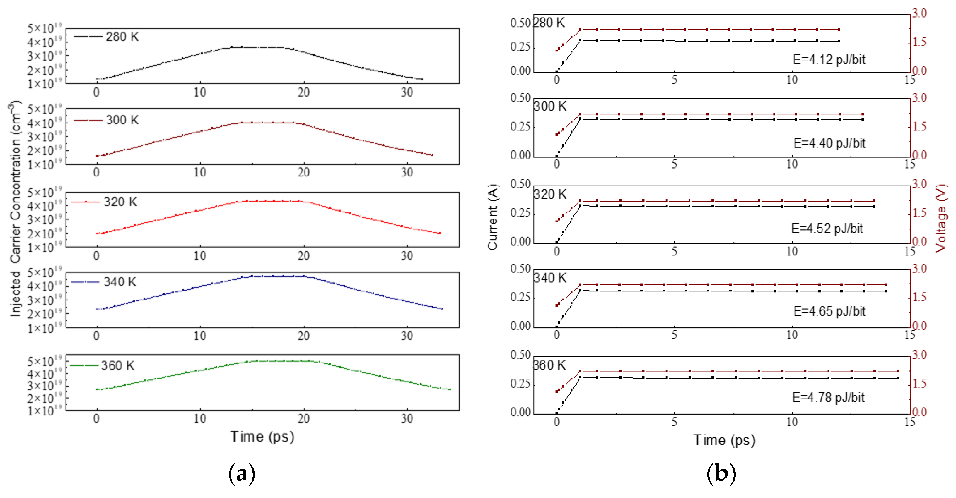
Figure 5a shows the change in injected carrier concentration with time. A pre-emphasized voltage of 2.2 V is applied for boosting the carrier drift until the aiming carrier concentration is achieved. In Figure 5a, as the temperature rises from 280 K to 360 K, the transit time increases from 26.4 ps to 29.1 ps because the rising temperature impairs the carrier mobility. The modulation rate is estimated by the carrier transit time, which varies from 34.3 Gbps to 37.8 Gbps. The energy consumption is calculated in Figure 5b. The energy consumption increases from 4.12 pJ/bit to 4.78 pJ/bit when the temperature rises from 280 K to 360 K. The longer rise time causes an increase in energy consumption. The performance parameters of the CIPMRM at different temperatures are listed in Table 1.

4.2. Line Width Effects

Figure 6a shows that the resonant wavelength shifts as the temperature changes for photonic MRMs. The resonant wavelength is 1550 nm when the temperature is 360 K. As the temperature falls from 360 K to 280 K, the resonant wavelength shows a blue shift, which ranges from 1550 nm to 1545 nm. It is estimated that the wavelength shifts by 0.075 nm/K. Figure 6b presents the resonant wavelength shifts from 1530 nm to 1565 nm as the waveguide width ranges from 405 nm (−10%) to 495 nm (+10%). The temperature will rise 466 K at least if the resonant wavelength is tuned by heating the modulator, and it will affect the normal operation of the device. One way to solve this issue is to reduce the FSR to a point where it is less than the shift of the wavelength. However, it will limit the size of MRMs.
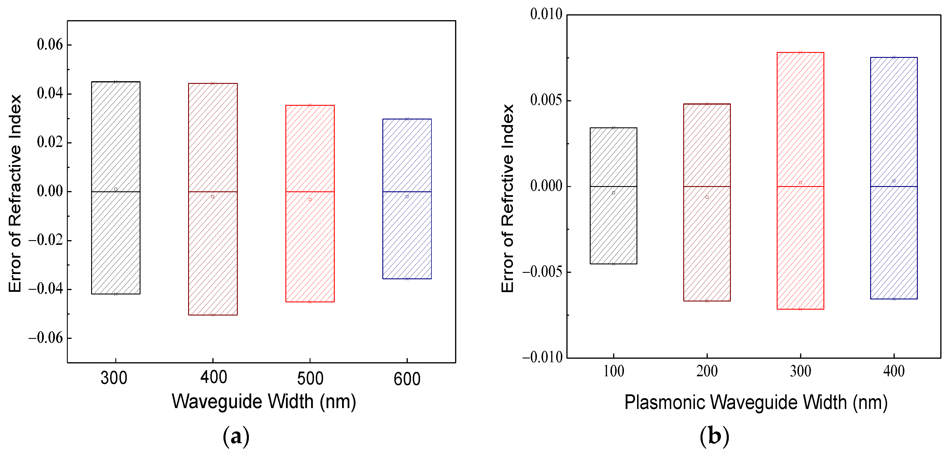
The resonance method by injected carrier concentration can solve this dilemma as the line width varies. The variation in the line width changes the refractive index, and it shifts the resonant wavelength. Figure 7 shows the error of the refractive index for a ±10% waveguide width variation. The change in the refractive index in the plasmonic waveguide is less than that in the photonic one because the plasmonic distribution is less insensitive to the waveguide width. Another benefit lies in the huge waveguide loss of the CIPMRMs. Because a large carrier is injected to compensate the line width error, the loss from the carrier will influence the resonance intensity. Having enough waveguide loss will weaken the effects of the injected carriers on resonance intensity. Therefore, the loss of the CIPMRMs is indispensable for achieving the resonance tuning method by carrier concentration.
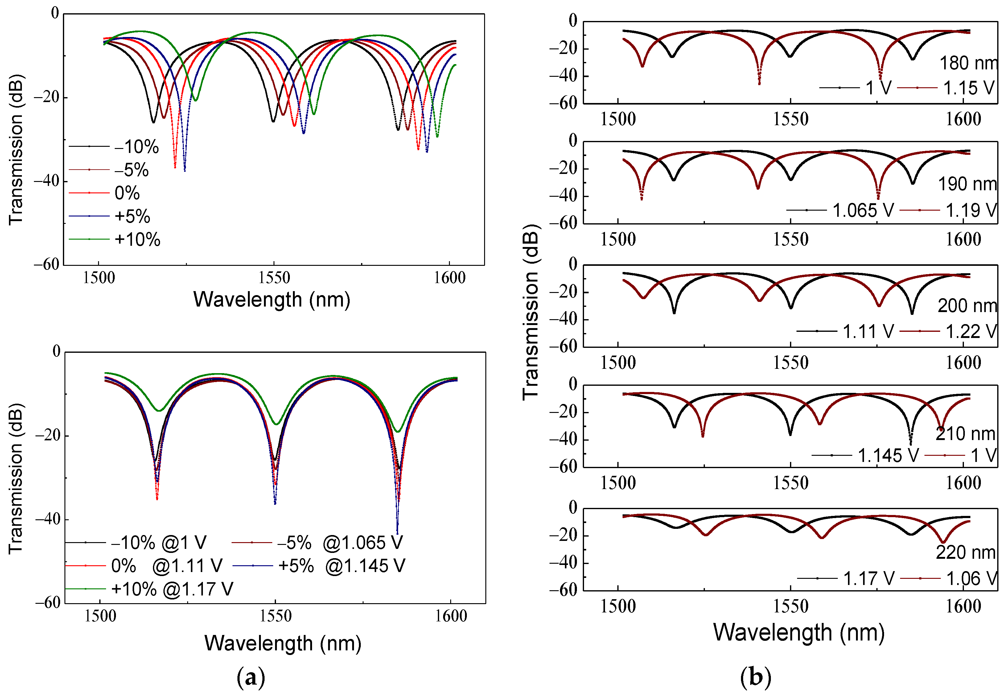
Figure 8a illustrates the method of resonant tuning by carrier concentration for line width variation. The resonant wavelength shifts from 1550 nm to 1565 nm as the line width ranges from 180 nm (−10%) to 220 nm (+10%). The resonance intensity changes slightly (−23.7 dB ~ −28 dB) as the width ranges from 180 nm to 220 nm. The resonance intensity is related to the relationship between micro-ring loss and coupling energy. The increasing waveguide widths result in a decreasing coupling gap. Therefore, the coupling efficiency changes slightly with the line width. Besides, the plasmonic waveguide loss decreases slightly from 0.56 dB/μm to 0.53 dB/μm as the width increases from 180 nm to 220 nm. Therefore, the resonance intensity is almost the same as the line width changes from −10% to 10%. By changing the initial voltage, the effect of the injected carrier offsets the increasing refractive index as line width increases. As a result, resonant wavelength sets at 1550 nm. The resonance intensity is near −20 dB for 220 nm plasmonic waveguide width. It is attributed to the loss of the massively injected carrier when 1.17 V voltage is applied. The “on-state” voltage is applied to shift the resonant wavelength away from 1550 nm for modulation (shown in Figure 8b). It presents the insertion loss and extinction ratio of CIPMRMs. The resonance intensity first increases and then decreases because of the impact of injected carrier concentration. As a result, line width error induced by lithography can be solved by voltage condition initialization (“on-state” voltage and “off-state” voltage condition).
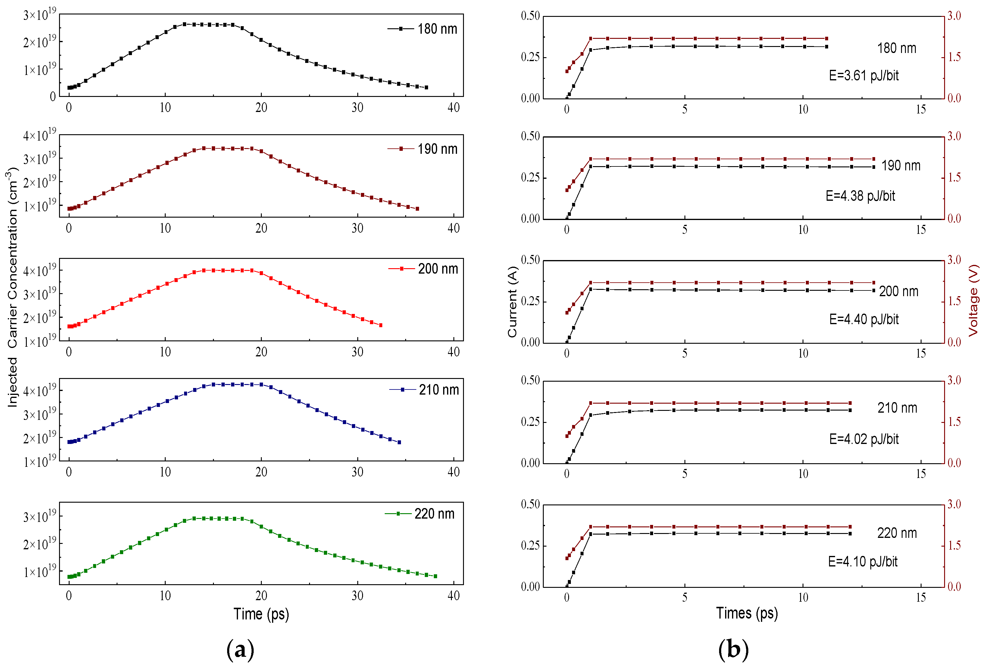
Figure 9a shows the change of carrier concentration with time for different widths of CIPMRMs. In Figure 9a, the modulation rate is estimated by the carrier transit time. The energy consumption is calculated in Figure 9b. All the results are listed in Table 2. It can be seen that the modulation rate varies from 30.3 Gbps to 36.5 Gbps, and the energy consumption varies from 3.61 pJ/bit to 4.4 pJ/bit.

5. Discussion and Conclusions

Photonic micro-ring modulators and Mach–Zehnder modulators are two kinds of commercial silicon modulators based on the CMOS process. The proposed CIPMRMs with the resonance tuning by injected carrier concentration provide another technology route for achieving a practical compacted modulator. Compared with thermo-optic resonance tuning, it achieves faster responsiveness because the variation in the carrier concentration is faster than that in the temperature. Besides, carrier concentration has better resonance tuning ability, and the micro-ring size is not limited by the temperature and free spectrum range. Although the plasmonic waveguide loss decreases the quality factor of the micro-ring resonator, which needs a more injected carrier to modulate, the energy consumption of CIPMRMs has a magnitude equal to that of MZMs [24]. In addition, the insertion loss of the CIPMRMs can be reduced in two possible ways. First, decreasing the plasmonic waveguide loss by increasing the oxide layer thickness would decrease the insertion loss. Second, decreasing the micro-ring size leads to lower insertion loss. This work will be proved in the future.
In summary, a fully CMOS-compatible CIPMRM based on a Cu-SiO2-Si plasmonic waveguide is proposed and demonstrated. It has a compact footprint of 49.3 μm2, a modulation rate of 36.5 Gbps, insertion loss of −9.8 dB, a static extinction ratio of 21.7 dB, and energy consumption of 4.40 pJ/bit as 2.2 V peak-to-peak voltage is applied. A method of resonance turning by injected carrier concentration is proposed in this work. The effective index is insensitive to the line width error in the plasmonic waveguide. Therefore, the resonant shift due to the ±10% line width variation can be tuned by carrier concentration. CIPMRMs provide a route for realizing the compacted size modulator for optoelectronic integration.

Author Contributions

Conceptualization, J.S.; methodology, J.S.; software, J.S.; validation, J.S.; formal analysis, J.S.; investigation, J.S.; resources, J.S.; data curation, J.S.; writing—original draft preparation, J.S.; writing—review and editing, J.S.; visualization, Z.L.; supervision, Z.L.; project administration, W.W.; funding acquisition, W.W. All authors have read and agreed to the published version of the manuscript.

Funding

This research was funded by National Key R&D Program of China (Grant No. 2018YFB2200203).

Institutional Review Board Statement

Not applicable.

Informed Consent Statement

Not applicable.

Data Availability Statement

The data that support the findings of this study are available from the corresponding author upon reasonable request.

Conflicts of Interest

The authors declare no conflict of interest.

References

  1. Gramotnev, D.K.; Bozhevolnyi, S.I. Plasmonics beyond the diffraction limit. Nat. Photonics 2010, 4, 83–91. [Google Scholar] [CrossRef]
  2. Dionne, J.A.; Atwater, H.A. Plasmonics: Metal-worthy methods and materials in nanophotonics. Mrs Bull. 2012, 37, 717–724. [Google Scholar] [CrossRef] [Green Version]
  3. Fedyanin, D.Y.; Yakubovsky, D.I.; Kirtaev, R.V.; Volkov, V.S. Ultralow-Loss CMOS Copper Plasmonic Waveguides. Nano Lett. 2016, 16, 362–366. [Google Scholar] [CrossRef] [PubMed]
  4. Dabos, G.; Manolis, A.; Tsiokos, D.; Ketzaki, D.; Chatzianagnostou, E.; Markey, L.; Rusakov, D.; Weeber, J.C.; Dereux, A.; Giesecke, A.L.; et al. Aluminum plasmonic waveguides co-integrated with Si3N4 photonics using CMOS processes. Sci. Rep. 2018, 8, 13380. [Google Scholar] [CrossRef] [PubMed] [Green Version]
  5. Salamin, Y.; Ma, P.; Baeuerle, B.; Emboras, A.; Fedoryshyn, Y.; Heni, W.; Cheng, B.; Josten, A.; Leuthold, J. 100 GHz Plasmonic Photodetector. ACS Photonics 2018, 5, 3291–3297. [Google Scholar] [CrossRef] [Green Version]
  6. Li, C.; Liu, Z.; Chen, J.; Gao, Y.; Li, M.L.; Zhang, Q. Semiconductor nanowire plasmonic lasers. Nanophotonics 2019, 8, 2091–2110. [Google Scholar] [CrossRef]
  7. Amin, R.; Maiti, R.; Gui, Y.L.; Suer, C.; Miscuglio, M.; Heidari, E.; Chen, R.T.; Dalir, H.; Sorger, V.J. Sub-wavelength GHz-fast broadband ITO Mach-Zehnder modulator on silicon photonics. Optica 2020, 7, 333–335. [Google Scholar] [CrossRef]
  8. Melikyan, A.; Lindenmann, N.; Walheim, S.; Leufke, P.M.; Ulrich, S.; Ye, J.; Vincze, P.; Hahn, H.; Schimmel, T.; Koos, C.; et al. Surface plasmon polariton absorption modulator. Optics Express 2011, 19, 8855–8869. [Google Scholar] [CrossRef]
  9. Ayata, M.; Nakano, Y.; Tanemura, T. Silicon rib waveguide electro-absorption optical modulator using transparent conductive oxide bilayer. Jpn. J. Appl. Phys. 2016, 55, 042201. [Google Scholar] [CrossRef]
  10. Kuang, Y.X.; Liu, Y.; Tian, L.F.; Han, W.H.; Li, Z.Y. A Dual-Slot Electro-Optic Modulator Based on an Epsilon-Near-Zero Oxide. IEEE Photonics J. 2019, 11, 1–12. [Google Scholar] [CrossRef]
  11. Wood, M.G.; Campione, S.; Parameswaran, S.; Luk, T.S.; Wendt, J.R.; Serkland, D.K.; Keeler, G.A. Gigahertz speed operation of epsilon-near-zero silicon photonic modulators. Optica 2018, 5, 233–236. [Google Scholar] [CrossRef]
  12. Amin, R.; Maiti, R.; Gui, Y.L.; Suer, C.; Miscuglio, M.; Heidari, E.; Khurgin, J.B.; Chen, R.T.; Dalir, H.; Sorger, V.J. Heterogeneously integrated ITO plasmonic Mach-Zehnder interferometric modulator on SOI. Sci. Rep. 2021, 11, 1287. [Google Scholar] [CrossRef] [PubMed]
  13. Melikyan, A.; Alloatti, L.; Muslija, A.; Hillerkuss, D.; Schindler, P.C.; Li, J.; Palmer, R.; Korn, D.; Muehlbrandt, S.; Van Thourhout, D.; et al. High-speed plasmonic phase modulators. Nat. Photonics 2014, 8, 229–233. [Google Scholar] [CrossRef]
  14. Haffner, C.; Chelladurai, D.; Fedoryshyn, Y.; Josten, A.; Baeuerle, B.; Heni, W.; Watanabe, T.; Cui, T.; Cheng, B.J.; Saha, S.; et al. Low-loss plasmon-assisted electro-optic modulator. Nature 2018, 556, 483–486. [Google Scholar] [CrossRef] [PubMed]
  15. Lao, J.; Tao, J.; Wang, Q.J.; Huang, X.G. Tunable graphene-based plasmonic waveguides: Nano modulators and nano attenuators. Laser Photonics Rev. 2014, 8, 569–574. [Google Scholar] [CrossRef]
  16. Qu, S.; Ma, C.C.; Liu, H.X. Tunable graphene-based hybrid plasmonic modulators for subwavelength confinement. Sci. Rep. 2017, 7, 5190. [Google Scholar] [CrossRef]
  17. Nong, J.P.; Feng, F.; Gan, J.A.; Min, C.J.; Yuan, X.C.; Somekh, M. Active Modulation of Graphene Near-Infrared Electroabsorption Employing Borophene Plasmons in a Wide Waveband. Adv. Optical Mater. 2022, 10, 2102131. [Google Scholar] [CrossRef]
  18. Dionne, J.A.; Diest, K.; Sweatlock, L.A.; Atwater, H.A. PlasMOStor: A Metal-Oxide-Si Field Effect Plasmonic Modulator. Nano Lett. 2009, 9, 897–902. [Google Scholar] [CrossRef]
  19. Zhu, S.Y.; Lo, G.Q.; Kwong, D.L. Phase modulation in horizontal metal-insulator-silicon-insulator-metal plasmonic waveguides. Optics Exp. 2013, 21, 8320–8330. [Google Scholar] [CrossRef]
  20. Soref, R.A.; Bennett, B.R. Electrooptical effects in silicon. IEEE J. Quantum Electron. 1987, 23, 123–129. [Google Scholar] [CrossRef] [Green Version]
  21. Treyz, G.V.; May, P.G.; Halbout, J.M. Silicon optical modulators at 1.3 mu-m based on free-carrier absorption. Ieee Electron. Device Lett. 1991, 12, 276–278. [Google Scholar] [CrossRef]
  22. Sun, J.; Kumar, R.; Sakib, M.; Driscoll, J.B.; Jayatilleka, H.; Rong, H.S. A 128 Gb/s PAM4 Silicon Microring Modulator With Integrated Thermo-Optic Resonance Tuning. J. Lightwave Technol. 2019, 37, 110–115. [Google Scholar] [CrossRef]
  23. Roberts, S. OPTICAL PROPERTIES OF COPPER. Phys. Rev. 1960, 118, 1509–1518. [Google Scholar] [CrossRef]
  24. Mastronardi, L.; Banakar, M.; Khokhar, A.Z.; Hattasan, N.; Rutirawut, T.; Bucio, T.D.; Grabska, K.M.; Littlejohns, C.; Bazin, A.; Mashanovich, G.; et al. High-speed Si/GeSi hetero-structure Electro Absorption Modulator. Opt. Exp. 2018, 26, 6663–6673. [Google Scholar] [CrossRef] [PubMed]
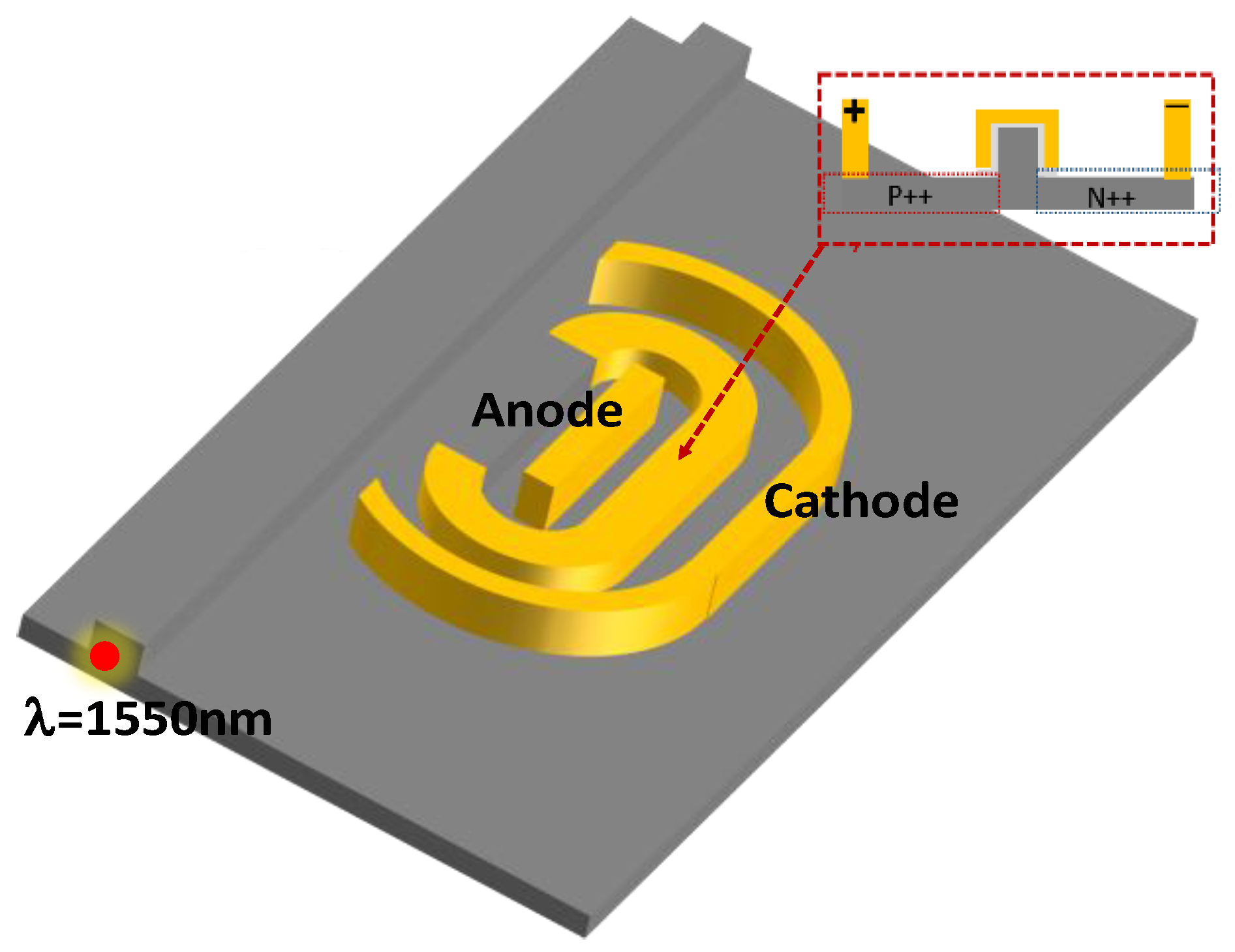
Figure 1. Schematic drawing of the carrier-injection plasmonic micro-ring modulator (CIPMRM).
Photonics 09 00272 g001
Figure 2. (a) The normalized electric field distribution in the plasmonic waveguide as the width varies from 100 nm to 300 nm; (b) the ratio of energy distribution in the plasmonic waveguide as the width varies from 100 nm to 300 nm; (c) the change in neff and loss with varying plasmonic waveguide width.
Photonics 09 00272 g002aPhotonics 09 00272 g002b
Figure 3. (a) The transmission curve as “on-state” and “off-state” voltage is applied; (b) the change in carrier concentration with time for different voltage conditions of the CIPMRM; (c) the change in carrier concentration with time for different widths of CIPMRMs; (d) the IV-t curve for different widths of CIPMRMs.
Photonics 09 00272 g003
Figure 4. (a) The method of resonance tuning by injected carrier concentration; (b) the transmission curve of “on-state” and “off-state” for different temperatures.
Photonics 09 00272 g004
Figure 5. (a) The change in carrier concentration with time for different temperatures; (b) the VI-t curve for different temperatures.
Photonics 09 00272 g005
Figure 6. (a) The resonant wavelength shifts with the temperature variation; (b) the resonant wavelength shifts with the line width variation.
Photonics 09 00272 g006
Figure 7. (a) The error of refractive index for different silicon waveguide widths; (b) the error of refractive index for different plasmonic waveguide widths.
Photonics 09 00272 g007
Figure 8. (a) The method of resonant turning by carrier concentration for different line widths; (b) the transmission curve of “on-state” and “off-state” for different line widths.
Photonics 09 00272 g008
Figure 9. (a) The change of carrier concentration with time for different widths of CIPMRMs; (b) the VI-t curve for different widths of CIPMRMs.
Photonics 09 00272 g009
Table 1. The performance of CIPMRMs for different temperatures.
Temperature
(K)
Insertion Loss (dB)Extinction Ratio (dB)Bit Rate
(Gbps)
Energy Consumption
(pJ/bit)
280−9.619.937.84.12
300−9.721.736.54.40
320−9.825.735.54.52
340−9.8537.7535.34.65
360−9.930.734.34.78
Table 2. The performance of CIPMRMs for different line widths.
Line Width (nm)Insertion Loss
(dB)
Extinction Ratio
(dB)
Bit Rate
(Gbps)
Energy Consumption
(pJ/bit)
180−9.316.131.23.61
190−9.316.332.14.38
200−9.821.736.54.40
210−8.927.134.14.02
220−6.610.430.34.10
Publisher’s Note: MDPI stays neutral with regard to jurisdictional claims in published maps and institutional affiliations.