Abstract
Ice accretion is a serious problem in cold climates, causing automobile and airplane accidents, as well as severe economic losses throughout various sectors. To combat these issues, many solutions have been developed, such as de-icing materials, which can delay or prevent the adhesion of ice to a surface through chemical, temperature, or physical means. To effectively assess the properties of a de-icing material, ice adhesion testing must be conducted, of which there are numerous types, each with their own characteristics. Unfortunately, the same material, tested with different methods, may provide very different ice adhesion values. This makes it difficult to properly characterize a material’s de-icing properties and compare values across the literature. In this review, we identified the main ice adhesion testing methods and compared ice adhesion values for a particular material with different testing methods. We then discussed some of the main issues with current ice testing methods and identified some of the main factors that may affect ice adhesion values, namely ice quality and the use of a mold, which may significantly affect the final ice adhesion results. Finally, we proposed a new, simple standard testing method, in an attempt to eliminate some of the issues with current ice testing methods.
1. Introduction
Ice, snow, and freezing rain can cause numerous issues for individuals, governments, and industries, due to the accumulation of ice [1,2,3,4]. When snow and freezing rain accumulate on surfaces and adhere, countless problems can occur such as downed powerlines, automobile accidents, and air traffic delays or accidents [3,4]. In addition to lost time, the economic impacts of ice accumulation can be damaging, costing billions of dollars per year in damage and lost revenue for aerospace and insurance industries, as well as individuals [1,2,3,4].
To limit the amount of damage caused by ice accumulation, ice removal and prevention are required as mitigation methods. While various ice mitigation methods are currently available, such as the use of road salt, propylene glycol, or ultralow ice adhesion surfaces, ice often still needs to be manually removed [5,6,7]. Thus, surfaces with low ice adhesion properties have been developed by researchers worldwide to delay or prevent ice adhesion on a substrate, and many of these surfaces rely on super-hydrophobic polymeric materials to inhibit ice adhesion [8,9,10,11,12]. However, testing these materials to assess their effectiveness can be fraught with issues, as there is no one specific standard to test the ice adhesion properties of a material. As a result, numerous methods exist for testing the ice adhesion of modern anti-icing and icephobic materials, many of which have variables that can affect the consensus of a material’s performance, as each research group may create its own custom ice testing apparatus [11,12,13,14]. In addition, determining an accurate ice adhesion strength of a material is difficult, making comparison among materials difficult. While the general agreement is that lower force values indicate better anti-icing performance of a material, a set standard to test ice adhesion is needed to verify material performance.
Previous reviews on ice adhesion testing, such as one by Rønneberg et al., gave a critical assessment of various utilized ice adhesion methods and noted several factors that may affect ice adhesion testing, such as the cooling rate, water impact velocity, humidity, and temperature [14]. The authors then suggested a standard ice adhesion method, based upon horizontal shear, to obtain the ice adhesion values of a substrate. Another review by Work and Lian, in 2018, raised several valid points regarding the various issues related to ice adhesion testing [15], including temperature, ice type, strain rate, and the effects of geometry on the interfacial stress concentrations, which are often overlooked in ice adhesion tests. The review article also noted that higher scatter was observed for mold poured ice, compared to impact ice for certain substrates [15]. Although these above reviews noted several key parameters that can affect the obtained ice adhesion, they did not consider the effects and interactions of the mold and the mold materials that are often used to contain the ice during static ice adhesion testing. These factors are important, as the mold is a significant part of the ice adhesion testing system because it is in direct contact with the ice during freezing. In addition, while Rønneberg et al. suggest a horizontal shear test as a standard, the exact mold requirements for the test were not specified [14]. Because mold materials may interact with, and affect, ice formation, crystallization, and the final properties of the ice [16,17], this review aims to bridge this gap by assessing the various techniques for testing ice adhesion, focusing on some of the challenges, issues, and advantages related to the use of molds in ice adhesion testing.
We also compare some of the most applicable testing methods that may serve as an ice adhesion standard for testing new de-icing and icephobic materials, and we propose a simple test method that minimizes some of the issues associated with current methods, building upon the standard proposed by Rønneberg et al. [14]. Our proposed standard stipulates metrics that were not previously considered, such as detailing a removable mold material for the test, the thickness of the substrate under test, and the material of the force gauge, to limit the interference of additional parameters on ice adhesion testing.
2. Ice Adhesion Testing Methods
Designing an ideal ice adhesion test or an ideal icephobic material is fraught with difficulty. For example, a study in 2019 by Irajizad et al. noted that, although various anti-icing materials and substrates have been proposed, many still cannot mitigate factors that can affect ice adhesion, and interfacial ice adhesion strength and long-term substrate durability may change after exposure to various environmental factors [18]. In addition, many new de-icing materials have difficulty retaining their low ice adhesion strengths after repeated icing-deicing cycles, therefore retesting these surfaces may result in different ice adhesion strength values [18]. Furthermore, the design of the ice adhesion experiment, which contains numerous factors, can also affect the ice adhesion strength values, as the ice detaches from them differently depending on the substrate. For example, sample thickness can add variability in the detachment mechanism of the ice, where normal stress dominates crack growth, while in very thin substrates, the normal force is essentially eliminated [18]. Therefore, when assessing ice adhesion testing methods, all of these factors have to be considered, especially the interactions between the ice and substrate, to obtain an ice adhesion value for a material. Therefore, these parameters and factors will be further discussed later on in this article.
While various methods exist to test ice adhesion on a flat surface, the vast majority can be classified into two main categories: direct mechanical testing and centrifuge testing. Mechanical testing is identified by its direct approach to dislodge the ice, and mechanical force is applied directly to the ice to free it from the material being tested [19,20,21], while in centrifuge tests, centrifugal force dislodges the ice from the material [19,20,21,22,23,24,25], utilizing indirect forces. While direct mechanical and centrifuge testing represent the majority of the research found in the current literature [11,12,13,14,15,20,21,22,23,24], additional miscellaneous tests have emerged that involve various apparatuses and methodologies, and these will be discussed separately in this review.
Mechanical testing can be further classified according to the four common direct methods, including horizontal shear test [10,25,26,27,28,29,30,31,32,33,34,35], vertical shear test [11,36], and tensile test [37,38,39], which are schematically depicted in Figure 1. Unlike centrifuge testing, mechanical testing can be conducted on stationary equipment, such as a tensile testing machine or a cold plate with a push rod [27,28,36]. As a result, the ice that dislodges using a mechanical testing approach is typically preserved and can be quickly assessed for surface irregularities [30,31,35]. By contrast, centrifuge testing typically results in the destruction of the ice sample, as it impacts the wall of the centrifuge testing chamber and is consequently destroyed [22,23,24].
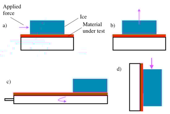
Figure 1.
Schematic showing the four most common ice adhesion testing methods reported in the literature: (a) horizontal shear (push test), (b) tensile test, (c) centrifuge, and (d) vertical shear.
There are numerous challenges when testing ice adhesion, with the main issue being the environment in which the ice is created. Ice must be tested in an optimally cold setting but without the development of frost [3,5,6], otherwise the ice can melt or change its structure, which can invalidate the data. Furthermore, the method used to form the ice will significantly impact the final results, as ice structures will differ depending on the environmental conditions during testing [30,40,41,42]. There are various methods to form ice on a surface, such as a spray system [42] or using bulk water ice [27,28,29,30,31,32,33,34,35,36]. However, these different ice formation processes will generate different types of ice with different qualities, resulting in different adhesion strength values. Furthermore, two different fracture modes can occur during ice adhesion testing, adhesive and cohesive, depending on various parameters, including the substrate and the conditions during freezing [36,37,38,39,40]. Cohesive failure occurs when the ice itself fails or breaks, often leaving some ice on the substrate surface [36,37,38,39,40]. Adhesive failure, by contrast, is the failure along the ice and substrate interface, resulting in a clean break [36,37,38,39,40].
The literature on ice adhesion testing often differentiates between static ice (non-impact ice) and impact ice [3,4,14,15,27,28,29,30,31,32,33,34,35,36,37,38,42]. Static ice is typically formed by pouring water into a mold and allowing it to freeze in a specific structure or geometry [27,28,29,30,31,32,33,34,35,36]. By contrast, impact ice essentially creates freezing rain, which impacts the surface of the material and freezes [42], and these two methods will create vastly different types of ice and thus different experimental conditions [3,4,15,27,28,29,30,31,32,33,34,35,36,37,38,42]. Because impact ice is commonly used to assess aircraft ice accretion, it involves more complex factors than static ice [3,4,42,43,44]. In addition, the precise ice area can be difficult to control, such as during freezing spray experiments, where the ice can encompass a mock wing of an aircraft [42].
In real-life scenarios, ice will form on various structures, such as wind-turbines or the wings of aircraft, due to the accretion of moisture over time, from freezing rain, heavy fog, or snow [42]. Determining this type of ice accretion and accumulation is different from static (non-impact) ice. In impact ice, the water droplets are supercooled upon impact with the substrate, while in static ice experimentation methods, freezing of the ice is often gradual [15,30,36,37,38,39,40,41,42]. Although static ice testing methods do not directly mimic the real-life accumulation of ice on surfaces, they do offer a much more simplified and straightforward methods to determine the ice adhesion strength of a surface in an idealized laboratory setting. Thus, while spray experiments are closer to a realistic environment, and a valid method to determine ice accretion patterns on structures such as aircraft, they are not ideal for evaluating the specific ice adhesion value of a particular surface, as they may incorporate too many variables during experimentation, and precise ice formation cannot be guaranteed. As a result, static ice testing offers a more idealized setting for determining the ice adhesion strength of a material, which may be beneficial when assessing new materials development in a laboratory setting. Thus, to provide a simplified standard, this review focuses on testing methods involving non-impact or static ice adhesion, as it is a more controllable environment.
Ice adhesion, which occurs through hydrogen bonding at the molecular level with a surface [28], can be defined as the ratio of removal force over the area of the ice on the macroscale, following:
where F is the removal force over the area of the ice interface area, A [14,27,28,29,30,31,32,33,34]. To create ice with a specific ice interface area, a mold is typically employed to create an ice block with a defined area [26,27,28,29,30,31,32,33,34,35]. However, the presence of a mold can create its own set of issues, which will also be discussed later in this review.
Lastly, one of the main issues facing testing ice adhesion involves the ice itself. Ice is a brittle material, and the basic structure of the ice, and how it forms, will directly affect how it behaves [30,40,41]. This inevitably means that scatter will be included in the majority of the data, and multiple tests need to be carried out for each condition or coating material, to assess its ice-adhesion strength. Thus, not all ice is the same, and a comparison cannot be made between ice that is made using different methods or even under different conditions [14,15,40,41].
2.1. Direct Mechanical Testing
2.1.1. Tensile Tests
Tensile ice adhesion can be used to test adhesion by producing a mode I failure mechanism while the ice is encased in a mold. This method can, therefore, be unique compared to other methods, though this method still produces stress concentrations at the interface, between the substrate and the ice, resulting in a difference in the Poisson’s ratio and Young’s modulus [34,36].
One of the earliest tensile test methods was proposed by Rothrick et al., in 1939 [43], as a means of testing ice adhesion on aircraft. This method utilized two metal blocks, which were held together by ice and pulled apart to test ice adhesion strength. However, the authors noted that one issue was the failure of the ice itself in tension, rather than failure at the ice-metal interface [43]. Another method, proposed by Andrews and Stevenson, utilized a plane-strain-based tensile ice adhesion test with a polytetrafluoroethylene (PTFE) disc in a cylindrical mold, to induce a defect into the ice, resulting in mode I fracture failure of the ice [44]. Recent studies have also used this method to test the ice adhesion of ultralow ice adhesion surfaces. For example, Tetteh et al. tested a self-lubricating icephobic coating (SLIC) surface in a cylindrical chamber with a mold, using this modified tensile method with a Teflon coated disc to dislodge static ice, and obtained a tensile stress of 0.17 MPa for the SLIC material [38].
2.1.2. Direct Shear Testing
Push Test
Various shear ice adhesion testing methods have been developed, and shear testing is the most commonly used method due to its relative simplicity. Within the shear testing category, for non-impact ice, horizontal ice adhesion testing, the horizontal shear (also known as the push test) is the most common [26,27,28,29,30,31,32,33,34,35]. In this method, water is typically poured into a mold placed on the surface material subjected to test, and a force is applied either directly to the mold to dislodge the ice while encased in the mold, or the mold can be removed, and the force applied directly to the ice using a force probe [14,15,26,27,28,29,30,31,32,33,34,35]. The maximum applied force is then recorded, and ice adhesion strength is calculated by considering the cross-sectional area of the ice within the mold [26,27,28,29,30,31,32,33,34,35]. Numerous mold geometries and mold materials have been used, though some of the most common are rectangular or cylindrical glass, plastic cuvettes [26,27,28,29,30,31,32,33,34], or pipette tips [45]. The mold is filled with water, and the sample material is placed on top, frozen, and then, the entire system is inverted to perform the adhesion test (Figure 2) [26,27,28,29,30,31,32,33,34]. In addition, a bottomless cuvette can be used that is simply placed on the material and filled [46,47]. Shear testing also benefits from the use of a cold plate to cool down the substrate material directly, rather than the cooling of the entire environment, to freeze the ice [35].
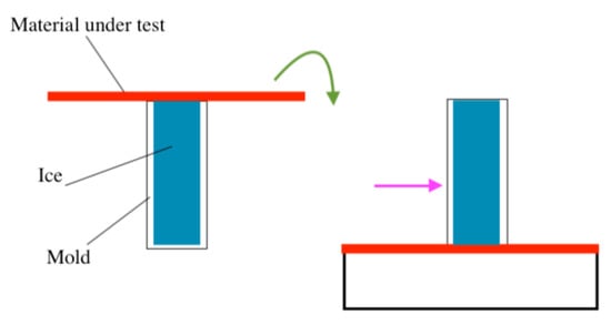
Figure 2.
Schematic of horizontal shear test, where a plastic or glass cuvette is filled with water, placed in contact with a substrate, frozen, and then inverted to perform the test.
This direct shear, or push test method, has been commonly used to test novel superhydrophobic de-icing materials, such as nano-textured superhydrophobic and lubricant-impregnated textured surfaces, as this method offers a simple surface for testing [26,27,28,29,30,31,32,33,34,35]. The ice can be directly placed in contact with the materials being tested without the need for additional steps, equipment, or setup. For example, Qian et al. used a bottomless cuvette to test a magnetically responsive lubricant-infused porous surface, where the deionized water was poured into the cuvette, frozen at −20 °C, with a placed probe in contact with the exterior of the cuvette, until the cuvette dislodged from the surface [30]. He et al. also used polypropylene (PP) tube molds, filled with water for 24 hours, to create ice cylinders and then, used a force probe to dislodge the tube-encased ice columns at a velocity of 0.1 mm/s [33]. Another variation on this method involves the vertical placement of the test apparatus, where the load cell pushes on the mold vertically, as displayed by Rønneberg et al. in 2019 [13]. In Meuler et al., glass cuvettes were used, with finely polished edges restricting the geometry of the ice at the edges, and each sample was frozen from the bottom up using a Peltier plate to reduce the stresses in the ice [48]. However, in the majority of studies utilizing the horizontal shear testing method, the force is applied directly to the exterior surface of a cuvette or mold, and not to the ice itself.
Other direct shear test methods include freezing a water droplet of a specific volume on the surface and pushing the water droplet with a small probe, as done by Ozbay et al. and Andersson et al. [49,50]. Ge et al. also pushed a frozen water droplet, using a horizontal probe at 1 mm/s to test and obtain the instantaneous shear force value, to determine the ice adhesion properties of an octadecyltrichlorosilane (OTS) superhydrophobic film [51].
Cone Test and Similar Methods
An additional shear test method was suggested by Haehnel and Mulherin [52,53], who proposed a 0° cone test to measure the ice adhesion strength of ice (Figure 3). In this setup, an inner cylindrical pin is contained within an outer cylindrical mold. The pin is then centrally inserted, with a notch at the bottom [53]. The mold can be coated with a material or substrate for testing, and then, the hollow area between the pin and the mold is filled with water, frozen, and the pin is pulled to test ice adhesion strength. Although this method commonly utilizes a tensile testing machine, the ice itself is put into shear [52,53]. Even though it is not as common as the push test method, it has been modified by other researchers, including Susoff et al. and Bharathidasan et al., who utilized modified zero-degree cone tests to assess various coatings [54,55].
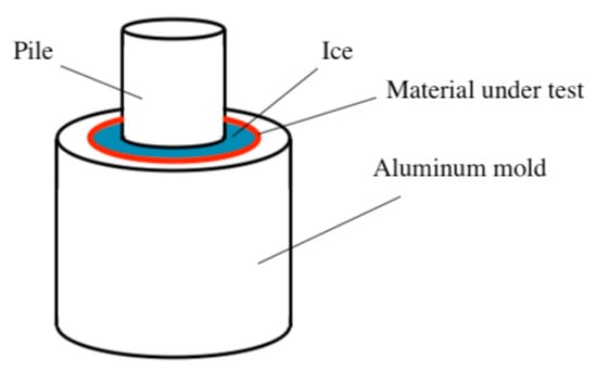
Figure 3.
Schematic of a standard 0° cone test to measure ice adhesion strength.
2.2. Centrifuge Adhesion Test
Centrifuge testing to measure ice adhesion strength was developed as an alternative method to direct shear testing. The centrifuge adhesion test (CAT) was developed by Laforte and Beisswenger at the CIGELE laboratories, at the Université du Québec à Chicoutimi (UQAC), in an attempt to create a standard method for testing the ice adhesion strength of surfaces and substrates [56]. In this method, an aluminum beam (32 mm in width and 30 cm in length) is loaded with a test sample, 32 × 50 mm in size, with ice attached to one end of the beam [56]. The speed at which the ice dislodges is then recorded to calculate the ice adhesion strength [56].
The CAT apparatus can be used to measure the ice adhesion strength by applying a small amount of ice to a counterbalanced 300 rpm/s rotating aluminum beam, and ice sample preparation and formations were performed in a controlled cold environment at –10 °C [21,56]. An assessment by Rønneberg et al. in 2019, conducted over 126 experiments, tried to determine the detachment adhesion force, with the use of piezoelectrical sensor cells, to assess the impact speed of the ice [57]. In addition, three unique ice formations types were tested: silicon bulk-mold formed ice, multi-droplet impact ice formed by a wind tunnel, and water freezing precipitation ice formation [57]. However, the results were inconsistent, with a standard deviation of up to 28% [57]. Thus, while accepted common sample preparation generally follows the bulk-mold ice formation sampling, this can be a limiting factor when determining real-world ice formation on surfaces and structures such as transmission lines and aircraft wing leading edges [21,56,57].
2.3. Miscellaneous Test Methods
Other than direct shear and centrifuge testing, other miscellaneous tests have been developed throughout the years. A few of these methods, such as beam, peel testing, blister, and laser spallation, will be briefly described here, as examples of alternative miscellaneous ice adhesion tests.
2.3.1. Beam Testing/Bending
A simple 3-point or 4-point beam loading method can be performed on in-situ bulk-mold formulation fresh and sea ice, and the flexural (bending) strength resistance of ice behavior has been a research interest for the past half a century to determine beam loading forces of ice sheets in freshwater and seawater [58,59]. For example, several factors, such as temperature, columnar grain structure, sample size, and salinity, were considered during experimental testing conducted by M. Karulina et al. [58]. With over 1.5k tests, the researchers determined flexural strengths for freshwater ice fell between 0.275–0.807 MPa, and seawater ice was between 0.109–0.415 MPa [58,59], and salinity (soluble salts) present in the ice was also a key factor in ice flexural strength. Additionally, a previous study, conducted in 1989, indicated the importance of grain structure and isothermal temperature effects on fresh and sea ice beams, indicating higher flexural strength beams at < 0 °C and ice columnar grain orientation [59]. Experimentation on the bulk-mold formation of ice samples was extensively conducted. However, there is the possibility for testing analysis on low-density ice formation with varying masses that may provide comparable data for experimentation in the future.
2.3.2. Peel Test
Testing the surface ice adhesion strength of solid substrates can also be assessed using the peel method, though this method has not been thoroughly investigated in the literature. A NASA study, conducted in 1987, used two experimental methods to measure shear adhesion and peeling [60]. Peeling force measures were obtained in environmental conditions indicative to aircraft with the consideration of the different icing formation conditions. Although the shear strength of different ice formations varied between 0.28–0.34 MPa, with the highest strength at 0.83 MPa, the thickness of ice, densities, and adhesion to the substrate were not systematically determined [60]. Peeling strength values varied from 5.25–8.75 N/cm [60], and the authors noted that peeling strength was considerably lower with increasing peel angles on stainless steel and neoprene substrate material [60]. No additional data were provided to examine concentration stresses or validation of their experiments. However, it is possible the peel test provided limited single mode I failure results.
2.3.3. Blister Test
A blister test utilizes the metal shaft-loaded ice substrate interface to produce a crack propagation from a defined crack initialization area on the ice substrate layer. This test configuration is designed to measure the fracture energies over the various ice thicknesses and surface irregularities (roughness) [61]. Gluffre et al. analyzed the various mechanical surface fractures between an aluminum-plug impactor force on the ice sheet by using optical microscopy [61]. The experimental results produced stable crack propagation with a roughness of root mean square (RMS) value of 0.35–0.55 µm [61]. However, the fracture energies to initiate fracture in rough surfaces were unchanged, while smooth surfaces were shown to have somewhat lower average fracture energies [61]. Although rather inconclusive, this study’s experimental configuration found surface irregularity and smoothness to be independent of fracture initiation with mixed failure modes.
2.3.4. New Ice Adhesion Testing Methods
One novel method for testing ice adhesion is laser spallation, which can be considered a modified version of the tensile test method. Saletti et al. also used laser spallation, which was adapted from the spalling test for polycrystalline ice, though this method has rarely been mentioned in the literature and though it provides a novel approach for ice adhesion testing [41]. In this technique, ice is encased in a mold and placed on a substrate surface. Then, a high energy pulsed laser is used to evaluate the tensile strength behavior of polycrystalline ice, by creating compressive stresses within the substrate [41]. These stresses propagate in the form of a tensile wave, at the free boundary, which impacts the ice and releases it from the substrate, providing an ice adhesion value. Archer et al. also used laser spallation to induce compressive stress waves, which acted as a tensile pulse on the substrate, removing the ice from the surface at a high amplitude [62].
With the increasing development of icephobic and de-icing materials using nanoscale fabrication techniques, determining ice adhesion strength at the nano and micro level is becoming increasingly important. In addition, ice adhesion strength testing at the micro- or nano-scale may offers more precise values, though it requires more expensive and complex equipment. For example, Matsumoto et al. used scanning probe microscopy (SPM) to test the ice adhesion strength of materials at the nano-scale level and found that ice adhesion values were higher values at the nanoscale level compared to macro-scale test results [63,64]. Building upon this, in 2018, Loho et al. used a novel nanoscratch technique to determine the ice adhesion strength of materials at the micro and nano level [65]. The researchers used a fluid cell tip made from Macor, a type of ceramic, to avoid thermal conduction and prevent the melting of the ice droplets during testing. The nanoscratch test consisted of three steps, where the fluid cell tip was moved up and over the sample, at certain increments [65]. During the nanoscratch, the tip was positioned 5 μm above the surface to measure sample tilt. Then, 150 μN of axial force was applied to the micro-nano sized water droplets, which were sheared off the substrate. The results demonstrated considerably higher ice adhesion values for stainless steel, compared to other shear tests.
3. Discussion
3.1. Issues with Current Ice Adhesion Testing Methods
Ice adhesion testing involves numerous factors, including the outside environment, the material or substrate being tested, temperature, the freezing rate, and the ice itself, which can change depending on a variety of factors under various experimental conditions, and can vary according to each test or experimental method. As a result, a tested substrate material, using different ice adhesion testing methods, may exhibit vastly different ice adhesion strength values. For example, as shown in Figure 4, the literature provides a range of possible ice adhesion strength values for uncoated aluminum surfaces, both polished and unpolished, between –9 and –15 °C, when tested using four different types of ice adhesion tests (laser spallation, direct shear, centrifuge, and tensile). In this particular example, ice adhesion strength values can encompass a large range, depending on the type of test, and even for the same material. Laser spallation had the largest value in this sample set, with a value of 180 MPa [62], while centrifuge testing exhibited some of the lower values (strengths), ranging from 0.42 to 0.24 MPa [13,21,22,23,24,25]. An even greater difference in values was found among the shear testing group, ranging from 4.5 to 0.11 MPa [38,39].
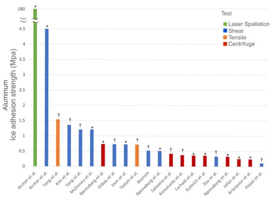
Figure 4.
Ice adhesion strength values of an aluminum surface, tested using four different ice adhesion methods (laser spallation, direct shear, centrifuge, and tensile), between –9 and –15 °C. Data obtained from [13,21,22,23,24,25,38,39,49,62,66,67,68,69,70,71,72]. * Polished or mirror polished aluminum surface. † Bare aluminum surface, as-received, or otherwise untreated aluminum surface.
While some of these differences can certainly be attributed to the experimental conditions and variations in sample preparation, an identical material, tested in the same study but with two different methods, may also exhibit completely different values. For example, Yang et al. tested a bare aluminum surface at –8 °C using tensile and shear test methods and obtained ice adhesion values of 1.54 and 1.21 MPa, respectively [39]. Tensile testing can also result in two different fracture modes, adhesive and cohesive, depending on variables such as the substrate under test, the ice structure that formed during the test, and the exact placement of the PTFE disc location [39]. Thus, even identical materials may give entirely different results, depending on the test method. This makes it exceedingly difficult to compare ice adhesion values across the literature and verify and validate the anti-ice adhesion behavior of various new materials, as the testing method may greatly influence, and potentially skew, the resulting ice adhesion values. Centrifuge testing may be especially prone to these issues, and the failure mode may be difficult to discern, due to the speed of the test and the effects of wind before complete separation of the ice, which may act on the ice differently if there are slight variations in ice structure, shape, or texture.
To determine some of the reasons for discrepancies in the aforementioned ice adhesion tests, various factors in the different test methods must be assessed. One possible source for variability is the mold that is used to hold and fabricate the static ice samples for ice adhesion testing. Molds appear to be a primary source of variability in the literature, as research groups currently use molds to contain various geometries, materials, and positions to contain the ice for ice adhesion strength testing [35,73]. In the most common test method, the horizontal push test, many studies have utilized plastic or glass cuvettes or pipette tips to form the ice, where the material being tested was placed directly on the cuvettes [21,22,23,24,25,26,27,28,29,30,31,32,33,34]. In addition, most of these molds could not be removed prior to testing, as most glass, and even plastic molds, are rigid and thus non-removable [35,73]. As a result, a few issues may occur, one of which is the lifting of the mold casing from the surface, due to the expansion of the ice as it crystallizes, forming a gap between the bottom edge of the mold and the material surface being tested, as shown in Figure 5a,b (red dotted circles) [73]. Consequently, when a force is applied to the exterior of the mold, as is often done in many of the horizontal and vertical shear tests in the literature, this gap may act as a crack initiation point [73]. Thus, the sample lifts from the substrate as the force is applied, and a wedge crack forms (Figure 6a,b) [73]. As a result, the force probe acts on the mold, rather than the ice itself, and the entire system, including the mold and the ice, are subjected to the test rather than just the ice itself. The gap between the mold and material under test will be detrimental to the test, as the ice will experience higher peeling forces under the action of shear, and these forces will occur on the side where the force is applied [68,73]. Therefore, displacement will occur not just in the x-direction (ux) but also in the y-direction (uy) [73]. Numerical analysis of this issue by Woll, in 2018, showed that this type of ice adhesion test can inherently cause rotation of the ice when pushed upon by a force probe [73], and this issue may also occur in cylindrical molds.
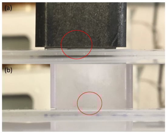
Figure 5.
Bottomless rectangular steel (a) and polycarbonate molds (b) used for horizontal shear testing, with dotted circles showing the resulting gap that forms after freezing at –10 °C [73].
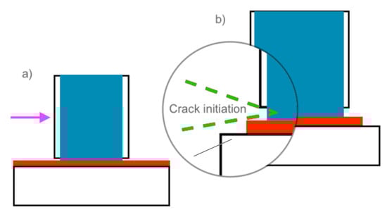
Figure 6.
Gap between the mold and the substrate caused by the expansion of the ice during crystallization (a), and resulting wedge crack upon loading (b).
As a result, a horizontal shear test can become a multimodal test, rather than a pure shear test, resulting in a consistent failure initiation site that is detrimental to the determination of ice adhesion strength. Thus, the presence of a mold may increase the amount of rotation and result in artificially lower obtained ice adhesion values [35,73]. Subsequently, large disparities in ice adhesion values may occur.
Another factor is the material of the mold itself, which can significantly affect the quality of the ice, as well as the expansion rate of the ice, due to thermal effects of the mold such as heat transfer and heat capacity. The formation of ice and crystallization are affected by surrounding conditions such as temperature and atmospheric moisture, and under normal above-freezing conditions, liquid water molecules will continuously break and reform hydrogen bonds in a non-uniform fashion. However, upon freezing, the water molecules in ice become fixed, and the resulting ice crystal will form various shapes such as plates, dendrites, or columns, and the hexagonal arrangement of water molecules is the most common [17,18].
If the water is encased in a mold, the mold material may affect the ice structure, due to the instability at the mold/water interface [17,18], and the temperature difference from the chill zone to the center may result in a temperature gradient, ΔT. This temperature gradient can create variability in the liquid temperature of the supercooled area ahead of the liquid interface, causing ice crystal instability and dendrite formation [17,18]. Furthermore, if changes in heat occur, the liquid water may undergo crystallization instability, and the solidification process becomes dendritic [17,18], which can also affect ice adhesion strength values. Metal materials may be especially prone to equiaxed growth with different ice morphologies, causing thermal dendrites to form, due to their high thermal conductivity [17].
An ideal form of ice nucleation would be homogenous crystallization, where the ice shows no clear directionality [17,18]. However, for ice to undergo homogenous ice nucleation, the water would have to be free from any interactions with a mold or container surface, impurities (solutes), or other variables. Experimentally, this is nearly impossible to do, therefore nucleation and ice solidification more likely occur as a result of heterogeneous nucleation, where variables such as impurities in the water or a mold surface may affect crystallization and, consequently, ice stability. Interfacial stability can result in unstable ice structures, which can ultimately affect the ice adhesion strength when measured experimentally. In a cubic mold, dendrites will form with preferred growth directions, because the water in the mold center will be at a different temperature than the water that is closest to the mold, resulting in fine nucleated ice crystals at the mold surface [17,18]. This may especially result in directional dendritic patterns forming in molds made of metal or glass. As shown in Figure 7a–c, the metal mold (c) exhibits a highly directional dendritic pattern, the polycarbonate shows moderate distribution (b), while a silicone rubber mold shows the growth of ice without obvious directionality (a), by comparison.
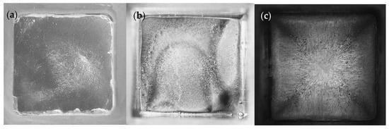
Figure 7.
(a–c): Digital photos of ice forms in various bottomless cubic molds (a) silicone rubber, (b) polycarbonate, and (c) steel.
As a result, even under identical conditions, the mold material may result in lower ice adhesion values, for example, if a polycarbonate rather than a glass mold is used, even if the geometries of the mold are identical [35,73]. For instance, when geometrically identical steel and polypropylene molds were used to determine the adhesion strength of a polydimethylsiloxane (PDMS) substrate, vastly different values were obtained, 9.56 kPa and 13.86 kPa, respectively, even under identical test conditions [73]. However, when ice was formed in a removable silicone mold with the same surface area, removed, and then tested, the resulting ice adhesion strength was 24.06 kPa [73].
The above mentioned factors may be attributed to the differences in the cooling rate of the water as it crystallizes into ice, due to the differences in heat transfer rates of the dissimilar materials, and ultimately, this may cause ice with different brittleness qualities to form. Thus, ice that forms in a mold with a high thermal conductivity value, such as aluminum (~237 W/m·K), will have vastly different properties than ice made in a polycarbonate mold (~21 W/m·K) [17,18,73,74]. This effect may apply not just to a small cuvette or pipette type molds, but also to cylindrical cone tests, where aluminum molds are typically used. As a result, metal molds, due to their thermal conductivities, may create brittle ice that results in lower ice adhesion values upon testing, which has been shown to affect ice adhesion testing [17,18,35,41]. Therefore, if the quality of the ice is not controlled from one test to another, or even within the same test category, it can be difficult to obtain an accurate ice adhesion measurement.
Rønneberg et al. noted that, during various experimental setups, ice nucleation conditions can vary, as the rate of water freezing results in different ice densities [13,14]. This micro-structural freezing deviation has also been cited in other ice studies [15,17,18]. An indeterminate freezing density effect of water can alter the ice mass and thickness (volume) of the three types of ice samples. Mass density within tested ice samples can be uncertain; therefore, an undetermined density in combination with the variable thicknesses added uncontrolled variation in the experimental observation. The authors accounted for the systematic aberration to ensure data accuracy; however, the adhesion strength can be considered erroneous when comparing three different types of ice formation that differ in mass and thickness. Thus, in an ideal ice adhesion test, rapid freezing of the ice should be avoided. Irajizad et al. also noted the role of material thickness on ice adhesion, citing that, when assessing ice adhesion, the ice adhesion reduction factor is a critical metric for assessing the ice adhesion strength of substrates with a uniform thickness, and this factor is non-dimensional [18]. This consideration also adds complexity when determining ice adhesion values, as the force dominating crack growth may be different from one substrate to another, especially with advanced materials such as magnetic slippery surfaces (MAGSS) or other substrates that induce a liquid-to-liquid interface [18]. Thus, when considering the thickness of different materials, this factor should also be taken into account, to acknowledge the variability between samples due to the differences in crack growth. Maintaining a universal thickness among substrates could also address environmental erosion and loss of anti-icing properties, as some substrates that are thicker may delay material loss, or loss of properties. Therefore, to do a proper side-by-side comparison, uniform thickness for different substrates could help to eliminate additional variabilities.
Other methods that do not use a mold, such as the water droplet method, may also have issues due to their size and a surface adhesion area that is too small for comparison with other test methods. The overall surface area of the water droplet itself may also be too large, causing the water droplet to freeze too quickly. In these tests, the surface area is much greater compared to other tests, due to the small volume of water, and the crystallization rate of the ice may be difficult to control. As a result, controlling the freezing rate of the water, to create a standardized test, is just as critical as the test method itself.
Another factor is the thickness of the substrate material being tested. Especially for non-rigid materials undergoing a horizontal push test, peeling forces may be generated as the ice undergoes shear. This may increase with increasing thickness, and adhesion strength values may thus decrease with increasing substrate thickness, even for the same material substrate type. This may, again, be due to the vertical displacements that will increase as sample thickness increases. In addition, this may be especially pronounced in experiments where a mold is present, causing the mold to ‘dig’ into the substrate on the opposite side of the force probe, and this phenomenon may be especially pronounced if the substrate material is very soft [73]. As a result, thinner samples of soft materials will generate increased adhesion strength values, and when testing materials for ice adhesion, thinner substrates would be preferred over thicker substrates, to minimize this effect.
Lastly, in a shear test where a force probe is applied, the position of the force probe may affect the final ice adhesion values as well, due to the vertical displacements increasing with increasing probe height from the substrate surface. Therefore, a force probe that is too far (vertically) from the surface, may produce more torque, which will rotate the ice rather than produce pure shear [73]. Thus, to reduce vertical displacements, the force probe should be located as close to the bottom of the ice as possible, to minimize the development of vertical displacements, and avoid this issue.
3.2. Proposed Standard for Testing Ice Adhesion
There have been a few attempts to create a standard test to measure ice adhesion strength. In fact, the 0° cone test was proposed as a standard method for measuring ice adhesion in 1998, by Mulherin et al. [53]. Other attempts at commercial standardization have also been put forward, such as by Wang et al. who, in 2014, proposed a vertical shear test method using standardized commercial equipment [36]. However, these methods utilize non-removable molds, and thus contain some of the issues described above.
To resolve some of these issues, we propose a simple, standard horizontal shear test for testing anti-icing substrates and materials that do not require extensive setup or equipment, and a schematic of this test setup is shown in Figure 8. This test utilizes some aspects of the horizontal shear test, with a few modifications, in an attempt to prevent some of the issues that may arise from previous test methods. While Rønneberg et al. also proposed a simplified standard shear ice test in 2020, but the proposed test did not specify several factors discussed in this review, specifically the encasement of the ice in a mold, the type of ice that forms when in contact with a mold, the thickness of the substrate under test, or the material of the probe, all of which can interact with the ice and affect the resulting ice adhesion values [14]. Therefore, this standard improves upon previously suggested standards by eliminating some of the issues associated with ice formation when it interacts with an unsuitable mold material. This proposed method is intended to be simple, inexpensive, and accessible for the majority of substrates, while also reducing the number of variables that can affect ice adhesion strength.
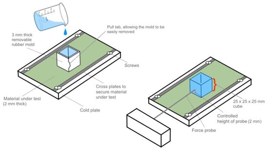
Figure 8.
Proposed standard for horizontal ice adhesion testing, with the use of an easily removal one-time use mold.
In this setup, a 2 mm thick substrate material (to undergo ice adhesion testing) is secured to a cold plate at –10 °C with screws and two cross plates to properly secure the material to the system and prevent movement during testing. By maintaining a standardized thickness among all tested substrate materials, the substrate thickness effect would be minimized, and comparable values could be obtained. Maintaining a standard substrate thickness would also diminish the effect of the ice ‘digging’ into the substrate being tested. This is especially important for soft materials, such gels, which may exhibit different ice adhesion strengths depending on their thickness [73]. In addition, the cold plate below the substrate would provide a stationary location for freezing the ice on the surface, without the need for the system to be placed in a freezer, though environmental temperature and humidity should still be controlled.
A disposable cubic, 25 × 25 × 25 mm bottomless 3 mm thick non-stick silicone rubber mold could then be placed on the substrate surface. The mold would also feature a slit along the corner side, combined with an integrated quick-release pull tab, as shown in Figure 8. This slit, which would be joined with mild adhesive, would allow for the rubber mold structure to securely hold water while it freezes, but still allow for the mold to be quickly removed by pulling the mold apart at the slit. Of note, this design would be one-time use, as the adhesive would likely deteriorate after initial use. Nevertheless, by integrating a quick-release tab, the mold could be removed by peeling it off the surface of the ice horizontally, rather than forcefully pulling the mold upward. Traditionally, removing a mold can inadvertently push or pull on the ice if done incorrectly or too forcefully, affecting the adhesion of the ice, the bonding with the surface, or even causing the ice to melt. This is especially true for low ice adhesion surfaces. Therefore, handling the ice during or after crystallization should be minimized, as it can affect the ice adhesion results. Consequently, the mold must be easily removable with minimal impact, and this proposed design would reduce the handling of the ice after freezing.
The mold material type also offers specific benefits in terms of thermal properties, as rubber materials, including silicone rubber, offer low thermal conductivities (i.e., 0.16 W/m·K) compared to other materials, such as metal or glass [74,75], and are inherently non-stick and removable but still sufficiently stiff to ensure a uniform ice specimen. Therefore, the rubber mold material would minimally affect the development of the ice, creating less dendritic and more homogenous ice with fewer imperfections, as shown in Figure 7a. After water is added and frozen, this mold can be easily removed, leaving just the clear ice on the surface and eliminating the effect of a mold during the experiment. Furthermore, the use of distilled water would reduce the effects of solutes or contaminants on ice crystallization, which can cause the ice to undergo heterogenous ice nucleation.
A 2 mm diameter force probe, coated with a 1 mm layer of silicone rubber, is then placed 2 mm above the substrate, in direct contact with the ice. As mentioned by Loho et al., force probes that are metal may inadvertently interact with the ice, either by superficial surface melting if the outside environmental temperature is too high, or adhering to the ice, if the temperature is too low [65]. Therefore, by thinly coating the probe with a polymer coating, this effect may be minimized or prevented. In addition, by placing the force probe 2 mm above the surface, any vertical displacement effects would be minimized, such as torque, during testing [73]. Thus, the 2 mm probe placement allows for enough clearance for the substrate and is sufficiently close to the surface to minimize vertical displacements, but it also prevents the probe from dragging on the substrate surface. Lastly, a probe speed of 0.025 mm/s would dislodge the ice from the surface, while also preserving the ice for further analysis.
This test setup may also be helpful in preventing cohesive failure, as the ice would be more homogenous and less dendritic, and the location of the probe minimizes vertical displacements that may lead to undesirable results. Nevertheless, if metallic substrates were tested, dendritic ice would likely still form due to the interactions between the ice and the metal surface. However, directionality, due to the presence of a mold, would still be eliminated, thus offering a more representative ice adhesion strength value.
4. Conclusions
Ice adhesion testing is a complex process fraught with numerous variables, such as the environment, humidity, ice quality, and mold type. After considering and discussing several common ice adhesion testing methods, we proposed an ice adhesion testing system that is simple, cost-effective, and can be used in nearly any environment or laboratory setting. This test eliminates some of the main variables that can affect ice adhesion testing, such as mold surface interactions, heterogenous and brittle ice formation, substrate thickness variability, vertical displacements, and multimodal failure, thus creating a test that is as close to pure shear as possible. This method also avoids issues associated with other ice adhesion testing methods, such as tensile tests, which can result in failure of the ice itself in tension, rather than failure at the ice-metal interface. It preserves the ice, allowing for follow up analysis, unlike in centrifuge tests where the ice is destroyed. Ensuring ideal conditions for ice adhesion testing is difficult, due to the numerous factors that can affect the test. However, with our proposed test setup, more uniformity between tests may be achieved, allowing for better comparison among different materials, and potentially between different research groups. Therefore, while this method may not be ideal for all scenarios or experimental approaches, it may provide a more idealized environment for pure shear or horizontal ice adhesion testing. Furthermore, by eliminating some of the factors that may complicate testing, such as expensive equipment or non-removable molds, this method may provide a simple, yet feasible, approach for potentially achieving standardized ice adhesion testing in the future.
Author Contributions
Conceptualization, M.B; writing—original draft preparation, M.B. and E.C.; writing—review and editing, M.B. and E.C.; All authors have read and agreed to the published version of the manuscript.
Funding
This research received no external funding.
Conflicts of Interest
The authors declare no conflict of interest.
References
- The Seattle Times. Available online: https://www.seattletimes.com/life/travel/the-economic-toll-of-winterrsquos-canceled-flights-53-billion (accessed on 12 June 2021).
- The Wall Street Journal. Available online: https://www.wsj.com/articles/winter-freeze-damage-expected-to-hit-18-billion-from-burst-pipes-collapse-roofs-11613757414 (accessed on 12 June 2021).
- Jones, K.F. Ice Accretion in Freezing Rain. Ice Accretion Freez. Rain. 1996. [Google Scholar] [CrossRef]
- Green, S. A Study of U.S. Inflight Icing Accidents and Incidents, 1978 to 2002. In Proceedings of the 44th AIAA Aerospace Sciences Meeting and Exhibit, Reno, NV, USA, 9–12 January 2006; American Institute of Aeronautics and Astronautics: Reston, VA, USA, 2006; p. 82. [Google Scholar]
- Lv, J.; Song, Y.; Jiang, L.; Wang, J. Bio-Inspired Strategies for Anti-Icing. ACS Nano 2014, 8, 3152–3169. [Google Scholar] [CrossRef] [PubMed]
- Ling, E.J.Y.; Uong, V.; Renault-Crispo, J.-S.; Kietzig, A.-M.; Servio, P. Reducing Ice Adhesion on Nonsmooth Metallic Surfaces: Wettability and Topography Effects. ACS Appl. Mater. Interfaces 2016, 8, 8789–8800. [Google Scholar] [CrossRef]
- Botta, G.; Cavaliere, M.; Holttinen, H. Ice Accretion at Acqua Spruzza and Its Effects on Wind Turbine Operation and Loss of Energy Production. BOREAS IV; FMI: Hetta, Finland, 1998; pp. 77–86. [Google Scholar]
- Beemer, D.L.; Wang, W.; Kota, A.K. Durable gels with ultra-low adhesion to ice. J. Mater. Chem. A 2016, 4, 18253–18258. [Google Scholar] [CrossRef]
- Kreder, M.J.; Alvarenga, J.; Kim, P.; Aizenberg, J. Design of anti-icing surfaces: Smooth, textured or slippery? Nat. Rev. Mater. 2016, 1, 15003. [Google Scholar] [CrossRef]
- Menini, R.; Farzaneh, M. Advanced Icephobic Coatings. J. Adhes. Sci. Technol. 2011, 25, 971–992. [Google Scholar] [CrossRef]
- Wang, P.; Li, Z.; Xie, Q.; Duan, W.; Zhang, X.; Han, H. A Passive Anti-icing Strategy Based on a Superhydrophobic Mesh with Extremely Low Ice Adhesion Strength. J. Bionic Eng. 2021, 18, 55–64. [Google Scholar] [CrossRef]
- Li, X.; Wang, G.; Moita, A.S.; Zhang, C.; Wang, S.; Liu, Y. Fabrication of bio-inspired non-fluorinated superhydrophobic surfaces with anti-icing property and its wettability transformation analysis. Appl. Surf. Sci. 2020, 505, 144386. [Google Scholar] [CrossRef]
- Rønneberg, S.; Zhuo, Y.; Laforte, C.; He, J.; Zhang, Z. Interlaboratory study of ice adhesion using different techniques. Coatings 2019, 9, 678. [Google Scholar] [CrossRef] [Green Version]
- Rønneberg, S.; He, J.; Zhang, Z. The need for standards in low ice adhesion surface research: A critical review. J. Adhes. Sci. Technol. 2019, 34, 319–347. [Google Scholar] [CrossRef]
- Work, A.; Lian, Y. A critical review of the measurement of ice adhesion to solid substrates. Prog. Aerosp. Sci. 2018, 98, 1–26. [Google Scholar] [CrossRef]
- Bhadeshia, H.K.D.H. “Solidification” Part IB Materials Science and Metallurgy: Metals & Alloys; University of Cambridge: Cambridge, UK, 2004. [Google Scholar]
- Huang, S.C.; Glicksman, M.E. Fundamentals of Dendritic Solidification—I. Steady-State Tip Growth. In Dynamics of Curved Fronts; Academic Press: Cambridge, MA, USA, 1988; pp. 247–261. [Google Scholar]
- Irajizad, P.; Al-Bayati, A.; Eslami, B.; Shafquat, T.; Nazari, M.; Jafari, P.; Kashyap, V.; Masoudi, A.; Araya, D.; Ghasemi, H. Stress-localized durable icephobic surfaces. Mater. Horizons 2019, 6, 758–766. [Google Scholar] [CrossRef]
- McDonald, B.; Patel, P.; Zhao, B. Droplet freezing and ice adhesion strength measurement on super-cooled hydro-phobic surfaces. J. Adhes. 2017, 93, 375–388. [Google Scholar] [CrossRef]
- Kulinich, S.; Farzaneh, M. Ice adhesion on super-hydrophobic surfaces. Appl. Surf. Sci. 2009, 255, 8153–8157. [Google Scholar] [CrossRef]
- Saleema, N.; Farzaneh, M.; Paynter, R.W.; Sarkar, D.K. Prevention of ice accretion on aluminum surfaces by en-hancing their hydrophobic properties. J. Adhes. Sci. Technol. 2011, 25, 27–40. [Google Scholar] [CrossRef] [Green Version]
- Koivuluoto, H.; Stenroos, C.; Kylmälahti, M.; Apostol, M.; Kiilakoski, J.; Vuoristo, P. Anti-icing Behavior of Thermally Sprayed Polymer Coatings. J. Therm. Spray Technol. 2017, 26, 150–160. [Google Scholar] [CrossRef]
- Arianpour, F.; Farzaneh, M.; Jafari, R. Hydrophobic and ice-phobic properties of self-assembled monolayers (SAMs) coatings on AA6061. Prog. Org. Coat. 2016, 93, 41–45. [Google Scholar] [CrossRef]
- Kulinich, S.; Farzaneh, M. On ice-releasing properties of rough hydrophobic coatings. Cold Reg. Sci. Technol. 2011, 65, 60–64. [Google Scholar] [CrossRef]
- Jafari, R.; Momen, G.; Farzaneh, M. Durability enhancement of icephobic fluoropolymer film. J. Coatings Technol. Res. 2016, 13, 405–412. [Google Scholar] [CrossRef]
- Sojoudi, H.; McKinley, G.H.; Gleason, K.K. Linker-free grafting of fluorinated polymeric cross-linked network bi-layers for durable reduction of ice adhesion. Mater. Horiz. 2015, 2, 91–99. [Google Scholar] [CrossRef] [Green Version]
- Bengaluru Subramanyam, S.; Kondrashov, V.; Ruühe, J.; Varanasi, K.K. Low ice adhesion on nano-textured super-hydrophobic surfaces under supersaturated conditions. ACS Appl. Mater. Interface 2016, 8, 12583–12587. [Google Scholar] [CrossRef]
- Chen, D.; Gelenter, M.D.; Hong, M.; Cohen, R.E.; McKinley, G.H. Icephobic surfaces induced by interfacial non-frozen water. ACS Appl. Mater. Interface 2017, 9, 4202–4214. [Google Scholar] [CrossRef] [PubMed]
- Subramanyam, S.B.; Rykaczewski, K.; Varanasi, K.K. Ice adhesion on lubricant-impregnated textured surfaces. Langmuir 2013, 29, 13414–13418. [Google Scholar] [CrossRef]
- Qian, H.; Liu, B.; Wu, D.; Zhang, F.; Wang, X.; Jin, L.; Wang, J.; Zhang, D.; Li, X. Magnetically responsive lubricant-infused porous surfaces with controllable lubricity and durable anti-icing performance. Surf. Coat. Technol. 2021, 406, 126742. [Google Scholar] [CrossRef]
- Zhang, G.; Zhang, Q.; Cheng, T.; Zhan, X.; Chen, F. Polyols-infused slippery surfaces based on magnetic Fe3O4-functionalized polymer hybrids for enhanced multifunctional anti-icing and deicing properties. Langmuir 2018, 34, 4052–4058. [Google Scholar] [CrossRef] [PubMed]
- Smith, J.D.; Meuler, A.J.; Bralower, H.L.; Venkatesan, R.; Subramanian, S.; Cohen, R.E.; Varanasi, K.K. Hydrate-phobic surfaces: Fundamental studies in clathrate hydrate adhesion reduction. Phys. Chem. Chem. Phys. 2012, 14, 6013–6020. [Google Scholar] [CrossRef] [PubMed] [Green Version]
- He, Z.; Vågenes, E.T.; Delabahan, C.; He, J.; Zhang, Z. Room Temperature Characteristics of Polymer-Based Low Ice Adhesion Surfaces. Sci. Rep. 2017, 7, srep42181. [Google Scholar] [CrossRef] [Green Version]
- Wu, D.; Ma, L.; Zhang, F.; Qian, H.; Minhas, B.; Yang, Y.; Han, X.; Zhang, D. Durable deicing lubricant-infused surface with photothermally switchable hydrophobic/slippery property. Mater. Des. 2020, 185, 108236. [Google Scholar] [CrossRef]
- Bleszynski, M.; Woll, R.; Middleton, J.; Kumosa, M. Effects of crosslinking, embedded TiO2 particles and extreme aging on PDMS icephobic barriers. Polym. Degrad. Stab. 2019, 166, 272–282. [Google Scholar] [CrossRef]
- Wang, C.; Zhang, W.; Siva, A.; Tiea, D.; Wynne, K.J. Laboratory Test for Ice Adhesion Strength Using Commercial Instrumentation. Langmuir 2014, 30, 540–547. [Google Scholar] [CrossRef]
- Mirshahidi, K.; Zarasvand, K.A.; Luo, W.; Golovin, K. A high throughput tensile ice adhesion measurement system. HardwareX 2020, 8, e00146. [Google Scholar] [CrossRef]
- Tetteh, E.; Loth, E. Reducing Static and Impact Ice Adhesion with a Self-Lubricating Icephobic Coating (SLIC). Coatings 2020, 10, 262. [Google Scholar] [CrossRef] [Green Version]
- Yang, S.; Xia, Q.; Zhu, L.; Xue, J.; Wang, Q.; Chen, Q.M. Research on the icephobic properties of fluoropolymer-based materials. Appl. Surf. Sci. 2011, 257, 4956–4962. [Google Scholar] [CrossRef]
- Andrews, E.H.; Lockington, N.A. The cohesive and adhesive strength of ice. J. Mater. Sci. 1983, 18, 1455–1465. [Google Scholar] [CrossRef]
- Saletti, D.; Georges, D.; Gouy, V.; Montagnat, M.; Forquin, P. A study of the mechanical response of polycrystalline ice subjected to dynamic tension loading using the spalling test technique. Int. J. Impact Eng. 2019, 132, 103315. [Google Scholar] [CrossRef] [Green Version]
- Kraj, A.G.; Bibeau, E.L. Measurement method and results of ice adhesion force on the curved surface of a wind turbine blade. Renew. Energy 2010, 35, 741–746. [Google Scholar] [CrossRef]
- Rothrick, A.M.; Selden, R. Adhesion of Ice in Its Relation to the De-Icing of Airplanes; Langley Memorial Aeronautical Laboratory: Hampton, VA, USA, 1939. [Google Scholar]
- Andrews, E.H.; Stevenson, A. Fracture energy of epoxy resin under plane strain conditions. J. Mater. Sci. 1978, 13, 1680–1688. [Google Scholar] [CrossRef]
- Yeong, Y.H.; Gupta, M.C. Hot embossed micro-textured thin superhydrophobic Teflon FEP sheets for low ice adhesion. Surf. Coat. Technol. 2017, 313, 17–23. [Google Scholar] [CrossRef] [Green Version]
- Cheng, T.; He, R.; Zhang, Q.; Zhan, X.; Chen, F. Magnetic particle-based super-hydrophobic coatings with excellent anti-icing and thermoresponsive deicing performance. J. Mater. Chem. A 2015, 3, 21637–21646. [Google Scholar] [CrossRef]
- Berry, D.H.; Wohl, C.J. Aerospace and Marine Environments as Design Spaces for Contamination-Mitigation Polymeric Coatings. In Contamination Mitigating Polymeric Coatings for Extreme Environments; Wohl, C.J., Berry, D.H., Eds.; Springer International Publishing AG: Cham, Switzerland, 2019. [Google Scholar] [CrossRef]
- Meuler, A.J.; Smith, J.D.; Varanasi, K.K.; Mabry, J.; McKinley, G.; Cohen, R.E. Relationships between Water Wettability and Ice Adhesion. ACS Appl. Mater. Interfaces 2010, 2, 3100–3110. [Google Scholar] [CrossRef]
- Ozbay, S.; Yuceel, C.; Erbil, H.Y. Improved icephobic properties on surfaces with a hydrophilic lubricating liquid. ACS Appl. Mater. Interfaces 2015, 7, 22067–22077. [Google Scholar] [CrossRef]
- Andersson, L.-O.; Golander, C.-G.; Persson, S. Ice adhesion to rubber materials. J. Adhes. Sci. Technol. 1994, 8, 117–132. [Google Scholar] [CrossRef]
- Ge, L.; Ding, G.; Wang, H.; Yao, J.; Cheng, P.; Wang, Y. Anti-icing property of superhydrophobic octadecyltri-chlorosilane film and its ice adhesion strength. J. Nanomater. 2013, 2013, 3. [Google Scholar] [CrossRef] [Green Version]
- Haehnel, R.B.; Mulherin, N.D. The bond strength of an ice–solid interface loaded in shear. Ice in Surface Waters. In Proceedings of the 14th International Symposium on Ice, Potsdam, NY, USA, 27–31 July 1998; pp. 597–604. [Google Scholar]
- Mulherin, N.D.; Haehnel, R.B.; Jones, K.F. Toward developing a standard shear test for ice adhesion. In Proceedings of the Eight International Workshop on Atmospheric Icing of Structures (IWAIS), Reykjavik, Iceland, 8–11 June 1998. [Google Scholar]
- Susoff, M.; Siegmann, K.; Pfaffenroth, C.; Hirayama, M. Evaluation of icephobic coatings—Screening of different coatings and influence of roughness. Appl. Surf. Sci. 2013, 282, 870–879. [Google Scholar] [CrossRef] [Green Version]
- Bharathidasan, T.; Kumar, S.V.; Bobji, M.; Chakradhar, R.; Basu, B.J. Effect of wettability and surface roughness on ice-adhesion strength of hydrophilic, hydrophobic and superhydrophobic surfaces. Appl. Surf. Sci. 2014, 314, 241–250. [Google Scholar] [CrossRef]
- Laforte, C.; Beisswenger, A. Icephobic material centrifuge adhesion test. In Proceedings of the 11th International Workshop on Atmospheric Icing of Structures, IWAIS, Montreal, QC, Canada, 13–16 June 2005; pp. 12–16. [Google Scholar]
- Rønneberg, S.; Laforte, C.; Volat, C.; He, J.; Zhang, Z. The effect of ice type on ice adhesion. AIP Adv. 2019, 9, 055304. [Google Scholar] [CrossRef] [Green Version]
- Karulina, M.; Marchenko, A.; Karulin, E.; Sodhi, D.; Sakharov, A.; Chistyakov, P. Full-scale flexural strength of sea ice and freshwater ice in Spitsbergen Fjords and North-West Barents Sea. Appl. Ocean. Res. 2019, 90, 101853. [Google Scholar] [CrossRef]
- Gow, A.J.; Ueda, H.T. Structure and temperature dependence of the flexural properties of laboratory freshwater ice sheets. Cold Reg. Sci. Technol. 1989, 16, 249–270. [Google Scholar] [CrossRef]
- Scavuzzo, R.J.; Chu, M.L. Structural Properties of Impact Ices Accreted on Aircraft Structures; National Aeronautics and Space Administration: Washington, DC, USA, 1987; pp. 41–42. [Google Scholar]
- Giuffre, C.; Dawood, B.; Yavas, D.; Bastawros, A. Numerical and Experimental Investigation of Ice Adhesion Using the Blister Test. SAE Technical Paper Series 2019, 2, 28–34. [Google Scholar] [CrossRef]
- Archer, P.; Gupta, V. Measurement and control of ice adhesion to aluminum 6061 alloy. J. Mech. Phys. Solids 1998, 46, 1745–1771. [Google Scholar] [CrossRef]
- Matsumoto, K.; Honda, M.; Minamiya, K.; Tsubaki, D.; Furudate, Y.; Murase, M. Measurements of correct ice adhesion forces to metal test plates in nano-scale by using SPM. Int. J. Refrig. 2016, 66, 84–92. [Google Scholar] [CrossRef]
- Matsumoto, K.; Akaishi, M.; Teraoka, Y.; Inaba, H.; Koshizuka, M. Investigation of method for measuring adhesion force of ice in nano/micro scale by using SPM. Int. J. Refrig. 2012, 35, 130–141. [Google Scholar] [CrossRef]
- Loho, T.; Dickinson, M. Development of a novel nanoscratch technique for quantitative measurement of ice adhesion strength. IOP Conf. Series Mater. Sci. Eng. 2018, 348, 012003. [Google Scholar] [CrossRef]
- Farhadi, S.; Farzaneh, M.; Kulinich, S. Anti-icing performance of superhydrophobic surfaces. Appl. Surf. Sci. 2011, 257, 6264–6269. [Google Scholar] [CrossRef]
- Kim, P.; Wong, T.S.; Alvarenga, J.; Kreder, M.J.; Adorno-Martinez, W.E.; Aizenberg, J. Liquid-infused nanostructured surfaces with extreme anti-ice and anti-frost performance. ACS Nano 2012, 6, 6569–6577. [Google Scholar] [CrossRef]
- Hejazi, V.; Sobolev, K.; Nosonovsky, M. From superhydrophobicity to icephobicity: Forces and interaction analysis. Sci. Rep. 2013, 3, 1–6. [Google Scholar] [CrossRef] [PubMed] [Green Version]
- Zou, M.; Beckford, S.; Wei, R.; Ellis, C.; Hatton, G.; Miller, M.A. Effects of surface roughness and energy on ice ad-hesion strength. Appl. Surf. Sci. 2011, 257, 3786–3792. [Google Scholar] [CrossRef]
- Jeon, J.; Jang, H.; Chang, J.; Lee, K.-S.; Kim, D.R. Fabrication of micro-patterned aluminum surfaces for low ice adhesion strength. Appl. Surf. Sci. 2018, 440, 643–650. [Google Scholar] [CrossRef]
- Mulroney, A.T.; Kessler, E.D.; Combs, S.; Gupta, M.C. Low ice adhesion surfaces using microtextured hydrophobic tapes and their applications in refrigeration systems. Surf. Coat. Technol. 2018, 351, 108–114. [Google Scholar] [CrossRef]
- Beeram, P.S.R.; Waldman, R.M.; Hu, H. Measurements of Ice Adhesion over Ice Mitigation Coatings Pertinent to Aircraft Icing and Anti-/De-Icing; In Proceedings of the 9th AIAA Atmospheric and Space Environments Conference, Denver, CO, USA, 5–9 June 2017; American Institute of Aeronautics and Astronautics: Reston, VA, USA, 2017; p. 3928. [Google Scholar]
- Woll, T.R. Ice Adhesion Analysis of Severely Aged PDMS Rubbers. Ph.D. Thesis, University of Denver, Denver, CO, USA, 2018. [Google Scholar]
- Powell, R.W.; Ho, C.Y.; Liley, P.E. Thermal Conductivity of Selected Materials; US Department of Commerce, National Bureau of Standards: Washington, DC, USA, 1966; Volume 8. [Google Scholar]
- Mu, Q.; Feng, S.; Diao, G. Thermal conductivity of silicone rubber filled with ZnO. Polym. Compos. 2007, 28, 125–130. [Google Scholar] [CrossRef]
Publisher’s Note: MDPI stays neutral with regard to jurisdictional claims in published maps and institutional affiliations. |
© 2021 by the authors. Licensee MDPI, Basel, Switzerland. This article is an open access article distributed under the terms and conditions of the Creative Commons Attribution (CC BY) license (https://creativecommons.org/licenses/by/4.0/).