Abstract
Different numerical solutions of a previously developed mass transport model for supercritical drying of aerogel particles in a packed bed [Part 1: Selmer et al. 2018, Part 2: Selmer et al. 2019] are compared. Two finite difference discretizations and a finite volume method were used. The finite volume method showed a higher overall accuracy, in the form of lower overall Euclidean norm () and maximum norm () errors, as well as lower mole balance errors compared to the finite difference methods. Additionally, the finite volume method was more efficient when the condition numbers of the linear systems to be solved were considered. In case of fine grids, the computation time of the finite difference methods was slightly faster but for 16 or fewer nodes the finite volume method was superior. Overall, the finite volume method is preferable for the numerical solution of the described drying model for aerogel particles in a packed bed.
1. Introduction
Supercritical drying of wet gels, such that they become porous aerogels, is the crucial step in aerogel production. The drying process uses supercritical CO2 as extraction medium and is; thus, conducted under moderate temperature but elevated pressure and; therefore, may be cost-intensive. A comprehensive overview of experimental studies and mass transport models investigating the kinetics of supercritical drying of gels is given by Şahin et al. [1]. Within the last two years, a several model of the supercritical drying for spherical gel particles were developed [2,3,4,5,6,7]. All these works show that the gel drying process for particles is significantly faster than for monoliths of comparable size [2,3,4,5,6,7]. This observation highlights the fact that aerogel particles are highly promising for future applications in industrial products. Selmer et al. developed their physical mass transport model for the supercritical drying of gel particles in a packed bed and analyzed mass transfer steps that limit the overall drying kinetic to optimize the process [2,3]. Hatami et al. developed a similar model and improved the optimizing procedure to allow a fast drying process with low CO2 consumption [6].
All reported mass transport models result in a set of coupled partial differential equations if the mass transport in the outer bulk fluid is considered additionally to the mass transport within the gel particles [3,4,5,6]. Şahin et al. and Hatami et al. discretized the spatial dimensions via the finite difference method and solved the resulting coupled set of differential-algebraic equations using the built-in ordinary differential equation solver in Matlab [4,5,6]. Selmer et al. discretized the spatial dimension of the gel particles via the finite difference method [8,9] and the spatial dimension of the bulk fluid in the autoclave via the finite volume method [3,10]. The finite volume method can preserve discretely important physical quantities such as mass [11].
During the supercritical drying process, the physical properties of supercritical CO2 and its mixture with ethanol or other solvents strongly depend on the composition of the mixture which varies during the drying process from pure ethanol (or another solvent) in the gel to almost pure CO2 [3]. Therefore, especially in mass transport models describing the supercritical drying process of small particles, a high spatial resolution of the domain with gel particles is required for accurate results. This, in turn, leads to high computation times.
For this reason, we set the aim of this work so as to investigate the behavior of numerical solutions of gel particles drying models according to their accuracy and efficiency, to increase the confidence in the simulation results reported so far.
In the present paper, two possible numerical discretization techniques of the resulting partial differential equations of Selmer et al.’s model [2,3] are implemented, namely the finite difference method [8,9] and the finite volume method [10]. Both discretization techniques are compared numerically by studying the quality of the approximations via Euclidean norm () and maximum norm () errors, as well as the efficiency via the condition numbers of the linear systems to be solved.
The supercritical drying of spherical, ethanol-filled silica gels packed in a cylindrical bed serves as the example system. Two initial ethanol concentrations in the bulk fluid, which represent the pressurization using CO2 with or without addition of excess solvent to the wet gels, are evaluated. Both pressurization techniques are applicable and implemented in supercritical drying processes.
2. Mass Transport Model of Supercritical Drying
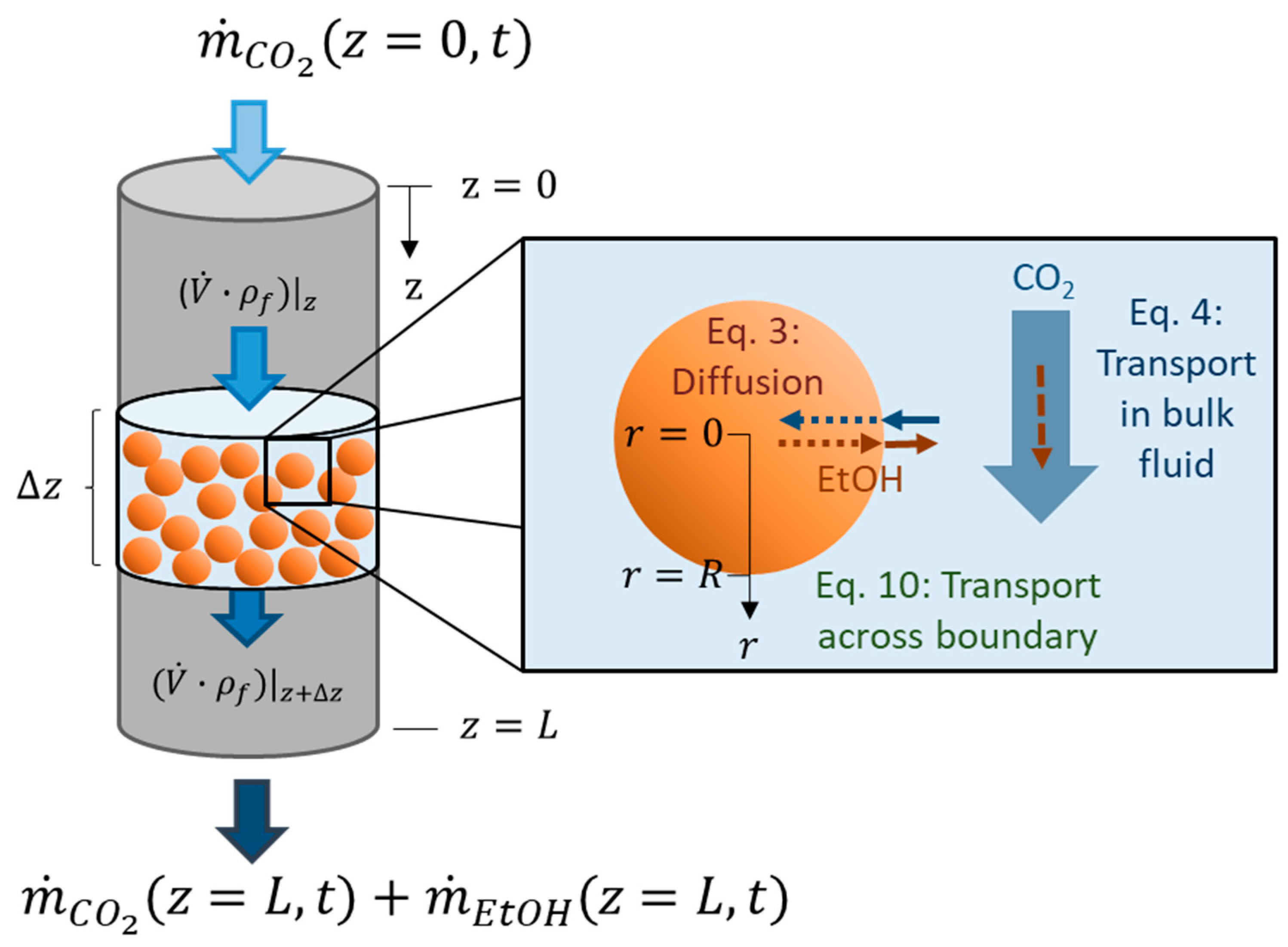
The aim of supercritical drying is to extract a solute (in our case ethanol) from a wet gel using supercritical CO2 (component 1). The mass transport model presented here, and discussed in Selmer et al. 2018 from the physical point of view [2], results in a system of coupled partial differential equations. The partial differential equations are written here in terms of concentration of ethanol (component 2), . In the drying process, ethanol is transported by diffusion from the inside of the porous gel particles (Equation (1)) to the bulk fluid (Figure 1). The flow of the bulk fluid through the packed bed is modeled by convection (Equation (2)) (Figure 1). The packed bed leads to non-ideal flow behavior, which is included through a time dependent dispersion factor (Equation (2)). Thus, two domains are considered: The spherical gel particles (subscript ), described by radial mass transport along the radial axis r; and the bulk fluid (subscript ), described by axial mass transport along the axial axis . Both domains are connected due to the mass transfer of ethanol across the boundary. This connection appears as a boundary condition for the mass transport within the particle (Equation (8)) and as a source term for the mass transport of the bulk fluid (Equation (2)). It is assumed in our model that the gel particles are monodisperse and evenly distributed along the cylindrical autoclave. Since the mass transport within the gel particles depends on the mass transport of the bulk fluid, which in its turn varies along the axial packed bed height the mass transport within the gel particles should also depend on their position in the packed bed. This fact is explicitly stated in (Equation (1)). The drying process is a dynamic process and thus depends on the time denoted with . The source term describes the ethanol being extracted from the gel particles (at axial position in the packed bed) into the bulk fluid. The term is calculated as the temporal change of the amount of ethanol (in moles) within all gel particles divided by the accessible volume of the bulk fluid (Equation (4)). stands for the cross-sectional area of the autoclave, for the porosity of the packed bed and for the length of the packed bed. The temporal change of the ethanol amount within the porous gel sphere is negative during the course of the drying since ethanol concentration with time decreases, but the source term itself is positive.
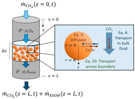
Figure 1.
Supercritical drying of gel particles in a packed bed (z—axial coordinate of packed bed, z = 0—top of packed bed, z = L—bottom of packed bed, —slice of packed bed, —CO2 flow,—ethanol flow, —volume flow, —fluid density (mixture of CO2 and ethanol), r—radial coordinate of spherical gel particle, r = 0—gel particle center, r = R—gel particle radius, t—time).
Physical properties of supercritical CO2 and its mixture with ethanol or other solvents strongly depend on the system parameters such as temperature, pressure and composition of the mixture [2]. The temperature and pressure are treated as constant during the drying process. The composition of binary mixture is directly related to the mixture concentration and ethanol concentration (Equation (5)) and varies during the drying from pure ethanol () to pure CO2 (). Physical properties, such as the effective diffusion coefficient , the mixture concentration and the fluid density as well as the parameters that are functions thereof, such as the interstitial fluid velocity (Equation (3)) and the mass transfer coefficient (Equation (8)), are highly dependent on the radial, axial and temporal distribution of the mixture compositions in the gel body and the bulk fluid . For example, at a pressure of 10 MPa and a temperature of 321 K, the parameters being directly dependent from the mixture composition can vary during supercritical drying between
- and for the effective diffusion coefficient (assumption: Gel porosity , gel tortuosity ),
- and for the mixture concentration and the fluid density ,
- and for the diffusion coefficient in the bulk fluid,
- and for the viscosity of the bulk fluid and between
- and for the resulting Schmidt number.
Parameters that are independent from the mixture composition are written in bold font throughout the text and as follows: The surface of a single spherical gel particle , the number of particles in the packed bed , the cross-sectional area of the autoclave , the length of the packed bed , the porosity of the packed bed and the mass flow rate of the ethanol–CO2 mixture .
Initial and boundary conditions are presented in Equations (6)–(8) for the gel particle domain and in Equations (10)–(12) for the bulk fluid domain. For each gel sphere (at a certain packed bed height ), the boundary conditions were given by the Neumann condition at the center (Equation (7)) and by the molar flux across the boundary layer at the surface (Equation (8)).
For the top of the packed bed, the Danckwerts’ boundary condition [12] was chosen so that no loss of ethanol across the upper boundary occurs due to dispersion of ethanol (Equation (11)). It was useful to define the flux of ethanol as follows:
In order to simplify the boundary condition at the top of the packed bed: The flux of ethanol across the upper boundary is set to zero (Equation (11)) according to the Danckwerts’ boundary condition [12].
At the bottom of the packed bed, a Neumann boundary condition was used (Equation (12)).
3. Numerical Solution of the Mass Transport Model
The coupled partial differential equations were solved numerically. Equation (1), which describes the mass transport within the porous gel particles, was always solved using the finite difference method (FDM), whereas Equation (2), which describes the mass transport of the bulk fluid in the packed bed, was solved using either the FDM (Section 3.1) or the finite volume method (FVM) (Section 3.2), (Supplementary Materials).
Equation (1) was discretized using an explicit scheme, since it is easy to implement. Without its dependencies on , , , Equation (1) is written as follows:
which gives, after applying the product rule,
Equation (14) was discretized using a forward difference for the time derivative and central differences for the spatial derivatives
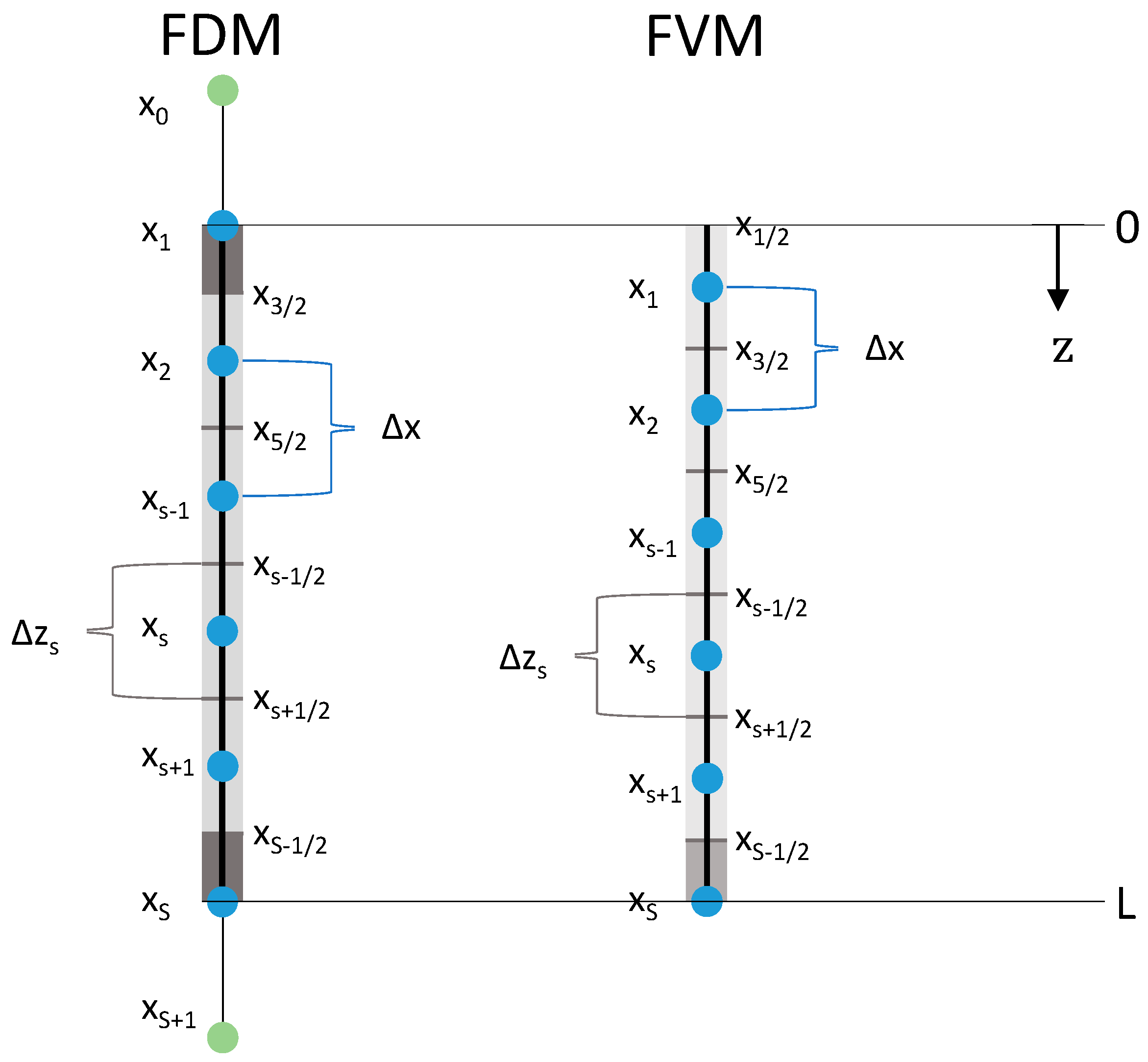
where the super index refers to time, to the axial index in the packed bed/autoclave domain (cf. Figure 2), and to the radial index of the gel particle domain. stands for the number of nodes used to discretize the gel particle domain. The temporal as well as both spatial discretizations were based on equidistant nodes resulting in constant time and constant radial steps . We can rearrange Equation (15) to
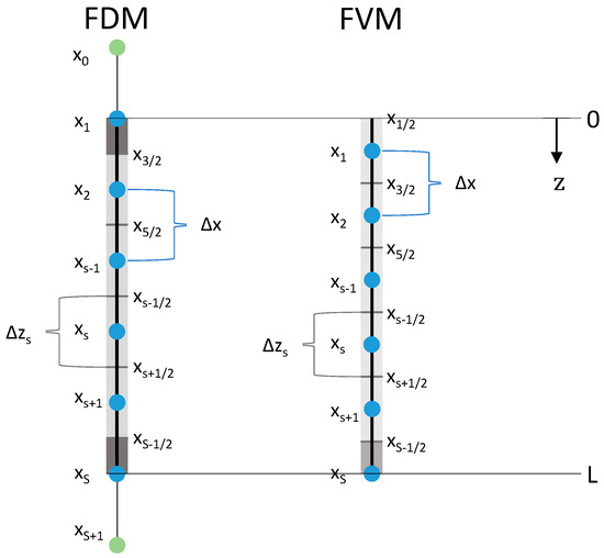
Figure 2.
Axial discretizations of the packed bed for FDM and FVM. —number of nodes, —sth node (blue), artificial node (green), distance between neighboring nodes, cell interface (in the middle of two neighboring nodes), length of volume element (grey boxes, boundary boxes in dark grey).
The initial condition of the gel particle domain was set to
The boundary conditions of the gel particle domain were discretized using central differences for the spatial derivatives. Two artificial nodes (, ) were placed beyond the boundaries and and calculated as follows:
The artificial node was used to solve Equation (16) for and the artificial node for .
The domain which describes the mass transport in the bulk fluid (Equation (2)) was solved with both numerical methods (Section 3.1 and Section 3.2). Without its dependencies on , , , Equation (2) was written as follows:
Using this definition of the flux (Equation (9)) allows Equation (20) to be rewritten as
The source term (Equation (4)), which describes the ethanol being extracted from porous gel particles to the bulk fluid in the packed bed with time, was discretized for both numerical methods in the same way (Equation (22)): It was calculated as the difference between the accumulated ethanol within a single porous gel particle (placed at axial position ) at time and at time divided by the time step and multiplied by the particles per bulk fluid volume (Equation (22)). The accumulated ethanol within a single porous particle was calculated by the summation of the ethanol concentration in each spherical shell element times the volume of each spherical shell element times the gel porosity (Equation (22)):
3.1. Solving the Diffusion-Advection Equation Using the Finite Difference Method
Finite difference methods are a flexible tool to discretize partial differential equations and easy to implement.
Figure 2 shows the equidistant axial discretization of the bulk fluid/packed bed domain for the FDM and the FVM (Section 3.2). For FDM, the first discretization node was placed at and the last one at . Therefore, both boundary volume elements/cells (grey boxes) were half of the length of the inner volume elements:
Additional to the number of nodes S in the packed bed domain, two more artificial nodes ( and ) outside the domain were needed to discretize the boundary conditions via the FDMs.
In the following, we will distinguish between two versions of possible discretizations using the FDM to solve numerically the diffusion-advection equation. The difference is given by the discretization of the advective term in Equation (20).
3.1.1. Discretization of Advection Term: Version A
In version A, the advective term was discretized. The discretization of Equation (20) using an explicit forward difference in time, a first order backward difference and a second order central difference in space results into
3.1.2. Discretization of Advection Term: Version B
In version B, the advective term was discretized instead of . Thus, the discretization of Equation (20) using an explicit forward difference in time, a first order backward difference and a second order central difference in space is given by
The corresponding discretized initial and boundary conditions for versions A and B are
Equations (24) and (25) can be rearranged to a linear system (Equations (29)–(33)) using the discretized boundary conditions (Equations (27) and (28)) and corresponding cell sizes (Equation (23)).
| Version A: | (31) | |
| Version B: |
| Where is nonzero only for the indices and given by | |||
| Version A: | Version B: | (32) | |
3.2. Solving the Diffusion-Advection Equation Using the Finite Volume Method
Under certain conditions, finite volume methods conserve mass discretely and thus are suitable here. In the FVM, the ethanol flux (Equation (9)) is evaluated at the cell interfaces and the ethanol concentration at the nodes (Figure 2, Equation (35)). To discretize the boundary conditions appropriately (cf. Equations (42)–(44)), the first discretization node was placed at and the last node at . Thus, the bottom boundary volume element was halved (Figure 2):
The grid definition of the FVM leads to a slightly different grid compared to the FDMs (including different ) using the same number of nodes . This is important for the subsequent comparison of both methods.
To solve Equation (21), we adapted the time-invariant complete flux scheme version developed by Farrell and Linke [11], which is based on Voronoï meshes [13]. They considered a numerical scheme for stationary problems, which we extended to time-dependent problems via integration: Equation (21) was integrated on a discrete cell (Figure 2) at time yielding Equation (35). Here describes the molar flux which crosses the interface between two neighboring cells. It can be divided into a homogeneous part and an inhomogeneous part (Equation (36)), which were calculated using Equation (37) to Equation (41) according to Farrell and Linke [11]. Their idea is based on complete flux schemes [14,15,16]. Thus, we used the supercritical drying model of gel particles in a packed bed as application example for the complete flux scheme developed by Farrell and Linke [11].
The boundary conditions of the FVM (Equations (42)–(44)) were chosen according to Equations (10)–(12). The difference to the FDM (Equations (26)–(28)) is that the boundary conditions are written in terms of ethanol fluxes . Equation (43) implies that no ethanol crosses the upper boundary which is analogous to the Danckwerts’ boundary condition [12]. At the bottom and at the end of the packed bed the ethanol flux is only influenced by the transported ethanol in the bulk fluid (pure convection without any dispersion) (Equation (44)), since the spatial derivative of the ethanol concentration in the bulk fluid stays zero at (Equation (12)).
Equation (35) can be rearranged using Equations (36)–(38), Equations (43) and (44) into a linear system (Equations (45)–(50)) to calculate the unknown ethanol concentration profile within the bulk fluid along the autoclave height. The division by the vector in Equation (45) is meant component wise (cf. Equations (34) and (47)).
| Where is nonzero only for the indices and given by | (49) |
4. Results and Discussion
First, we numerically analyze the accuracy of the presented discrete schemes by studying the convergence behavior and the closure of the mole balance. Second, we discuss the computational efficiency of all three methods by examining the condition number as well as the duration of the computation.
The following drying conditions were utilized for all calculations: System pressure , system temperature , gel sphere radius , gel porosity gel tortuosity , ethanol molar fraction within the gel sphere at the start of the drying , ethanol molar fraction within the gel sphere at the end of the drying (depends on system temperature and defines the drying end) , packed bed porosity , volume of packed bed , diameter of packed bed , mass flow rate of the ethanol–CO2 mixture . For Figure 9 additional calculations were conducted (see caption of Figure 9).
4.1. Accuracy
4.1.1. Convergence Behavior
We would like to know how the number of nodes influences the quality of the calculated solution.
In the following, the convergence behavior is evaluated for two different initial ethanol concentrations in the bulk fluid (Equation (26), Equation (42)), which represent the pressurization using CO2:
- (a)
- With excess ethanol: corresponding to ;
- (b)
- Without excess ethanol: corresponding to .
The analysis of the convergence behavior is based and presented here in form of the ethanol molar fraction instead of the ethanol concentration, since the molar fraction (being proportional to the concentration (Equation (5))) varies from 0 to 1, which allows the reader to easily interpret the results.
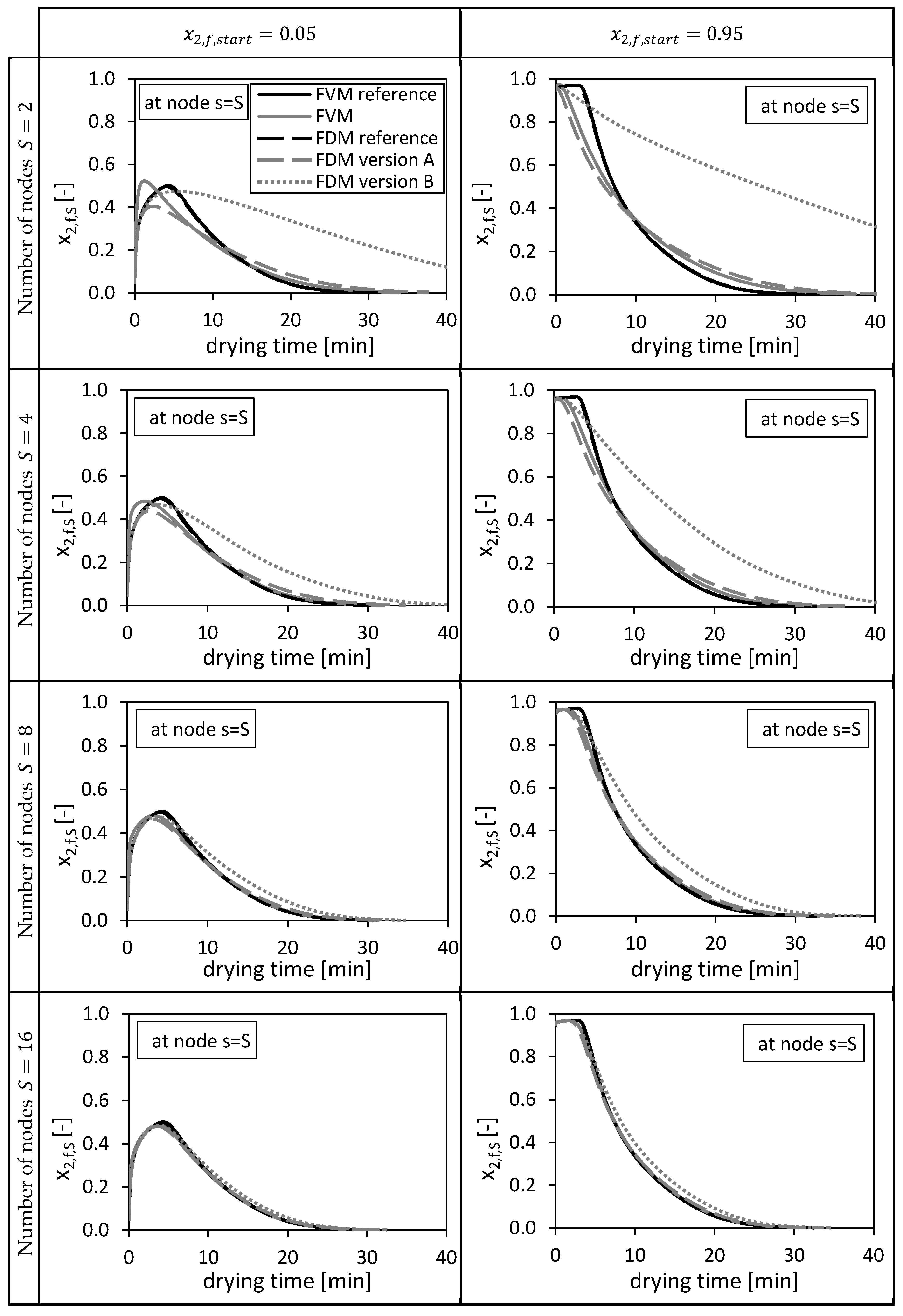
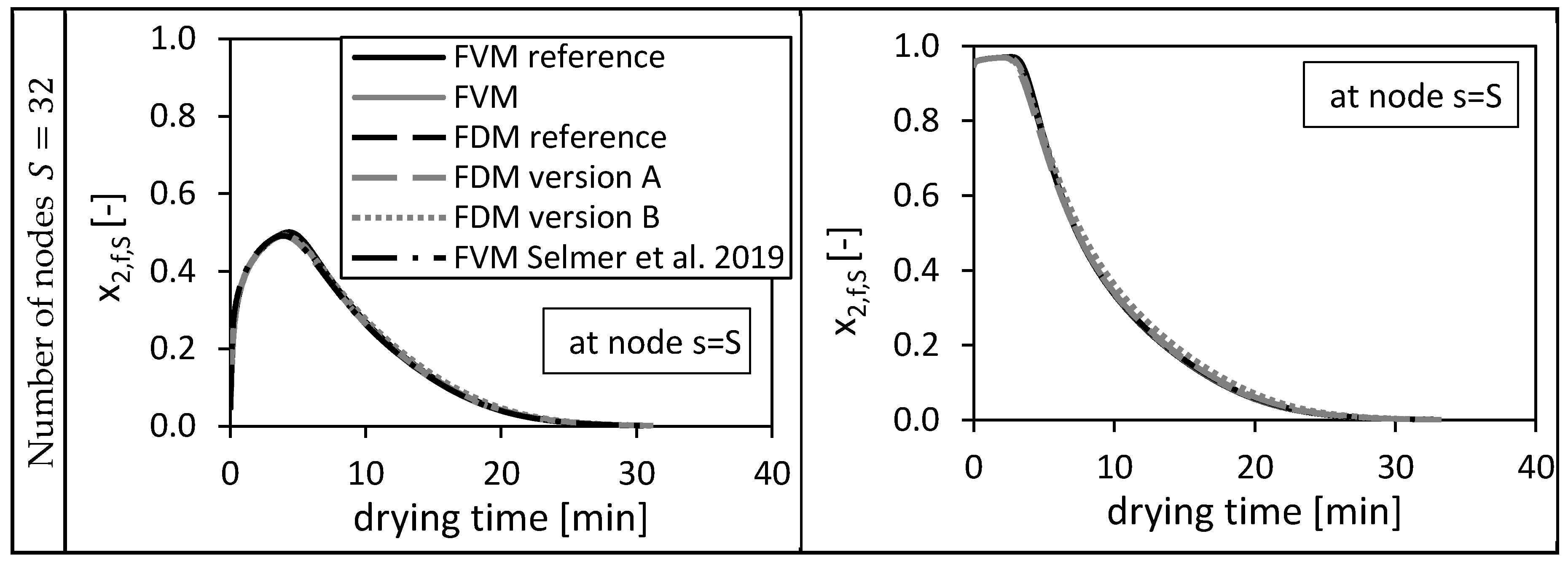
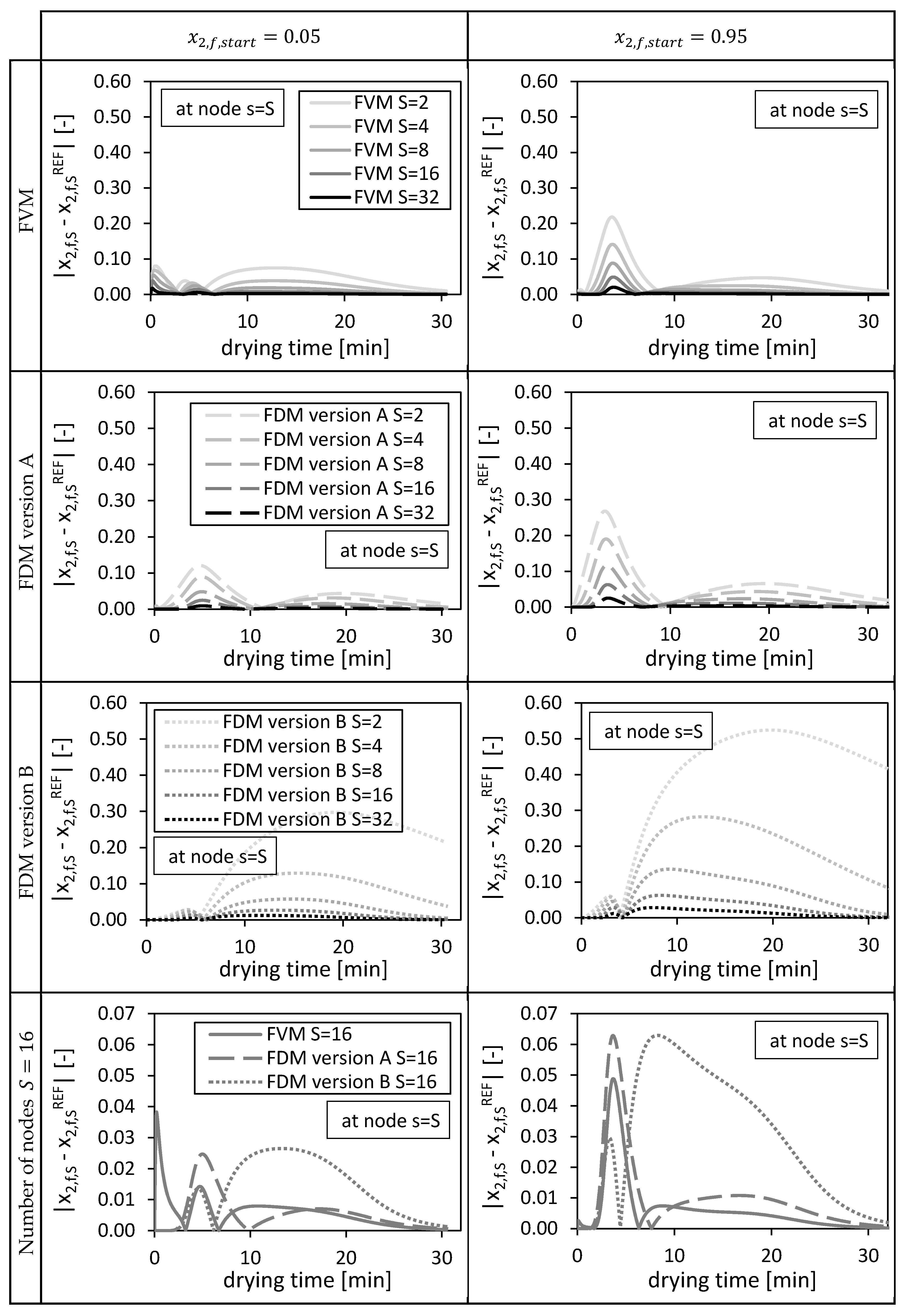
First, the solutions of the numerical methods are compared at the node (bottom of the packed bed), since this node position is equal for all three methods (Figure 2). Thus, the molar fractions of ethanol in the bulk fluid at the bottom of the packed bed depending on the drying time are shown in Figure 3 for different numbers of grid nodes (). In our case, an analytical solution is missing so that solutions on a fine grid () are used as reference in all cases. The solutions of the FDM calculations are compared with a fine FDM reference solution calculated with FDM version A and grid nodes in total. The solutions of the FVM calculations are compared with a fine FVM reference solution also calculated with grid nodes. Two different reference solutions were needed, since especially the first node of the FDM and the FVM differs in its principal position (Figure 2). Both reference solutions presented in form of ethanol molar fraction are additionally shown in Figure 3 and converge to same solutions.
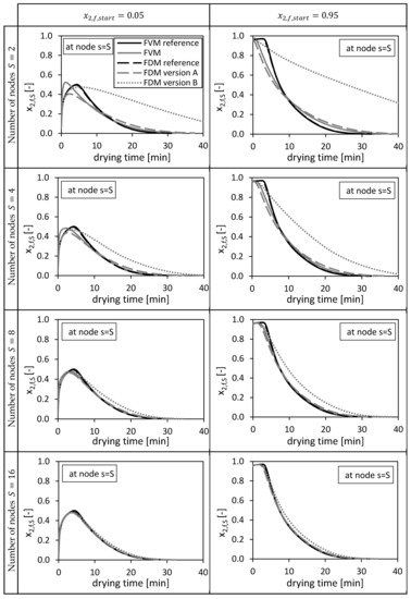
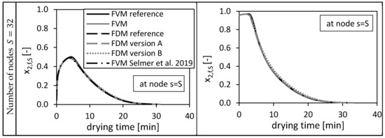
Figure 3.
Calculated ethanol mole fraction in the bulk fluid x2,f,s at node s = S, using = 0.05 (left panels) and = 0.95 (right panels). Calculated by the FVM, FDM version A and B and the FVM with the settings used in Selmer et al. 2019 [3] depending on the drying time and the number of nodes S. Calculation settings: N = 26, SREF = 64, Δt = 0.05 s (for FVM, FDM version A and B), Δt = 0.1 s (for FVM Selmer et al. 2019 [3]), S = 20 (for FVM Selmer et al. 2019 [3]).
From Figure 3 it is obvious that increasing the total number of nodes increases the quality of the solutions for all three methods. For and , the FVM overshoots slightly the reference solutions in the first drying minutes due to a sharp increase of the molar fraction at this position (bottom of the packed) in the beginning of the drying process. The FDM version B prolongs the drying process compared to the reference solutions.
In the previous paper [3], 20 nodes were taken for the same calculation using the presented FVM and as initial condition. From Figure 3 it is obvious that these 20 nodes (marked as FVM Selmer et al. 2019) were sufficient to calculate a solution being close to the fine reference solution.
The resulting absolute deviations (at position ) between the solutions of the investigated numerical methods and their corresponding reference solutions are shown in Figure 4. In general, the deviations of the solutions from the fine reference solutions (Figure 3: in black), restricted to the corresponding coarser meshes, decrease with an increasing number of nodes, indicating convergence (Figure 4). The initial condition of the bulk fluid in the packed bed influences the height as well as the temporal distribution of the deviations (Figure 4). For high temporal changes (Figure 3, ) high deviations in case of FDM version A and FVM (Figure 4, ) can be observed. Even higher deviations at coarse grids () were observed for FDM version B due to a coarser approximation of the convective mass transport in the packed bed (Equation (25)) compared to version A (Equation (24)). The FVM shows smaller deviations compared to the FDMs, except for the usage of and nodes in case of where relative high deviations could be observed in the first drying minutes (Figure 4). These deviations are induced by the approximated boundary condition of the FVM at the bottom of the packed bed (Equation (44)). The interstitial fluid velocity and thus the ethanol flow at could not be evaluated at the cell interface and had to approximated by using the ethanol concentration at the final node to estimate the searched ethanol flow (Equation (44)).
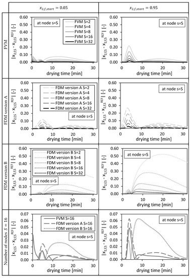
Figure 4.
Absolute deviation from reference solution at final node s = S for the FVM, FDM version A and B, using = 0.05 (left panels) and = 0.95 (right panels), depending on the drying time and the number of nodes S. Calculation settings: N = 26, SREF = 64, Δt = 0.05 s (for FVM, FDM version A and B).
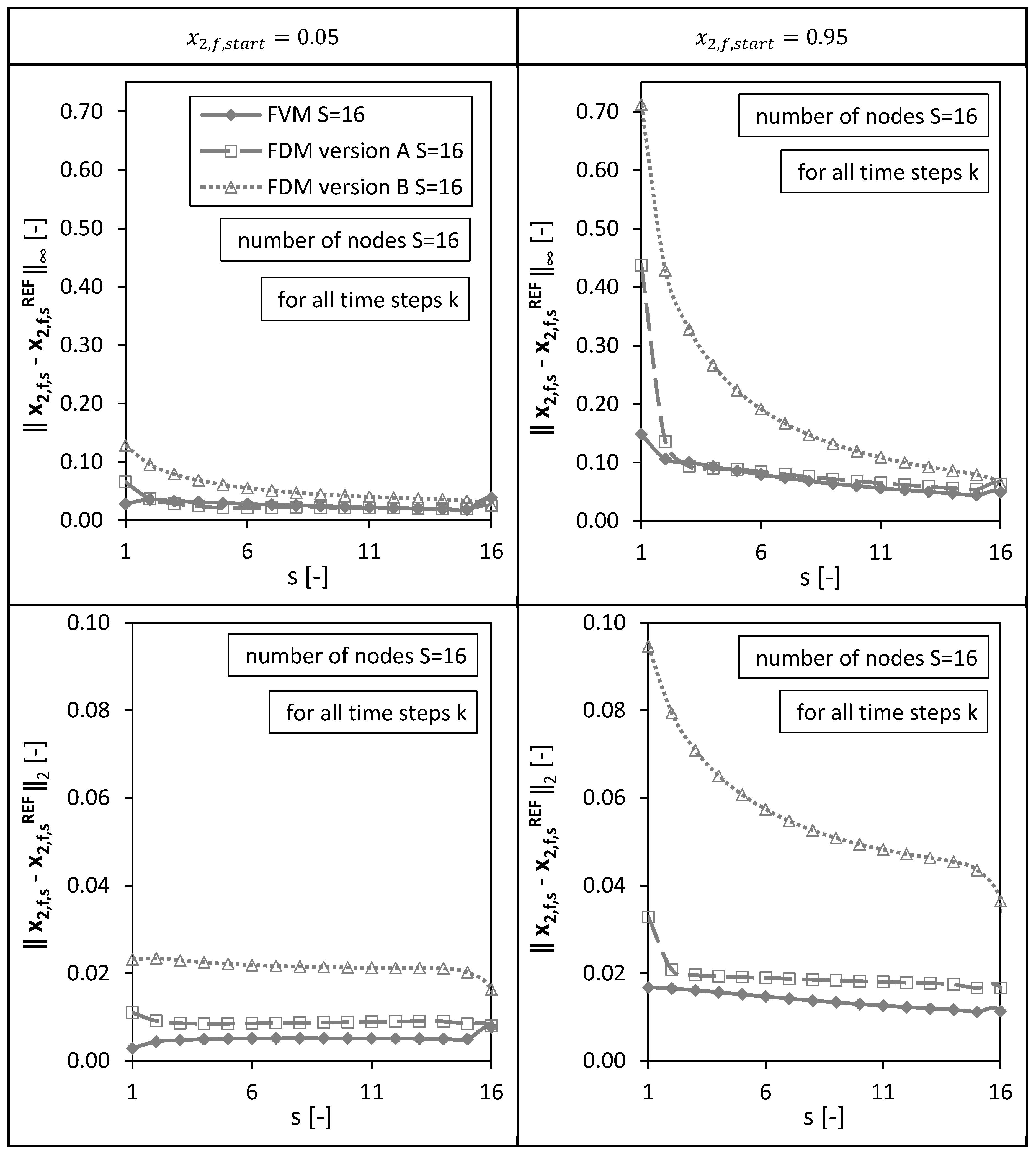
In a second step, the solutions of the numerical methods were analyzed not only at the final node (bottom of the packed bed) for varying drying times (as presented above), but also for all other nodes ( ) in order to have a spatial error distribution (Figure 5).
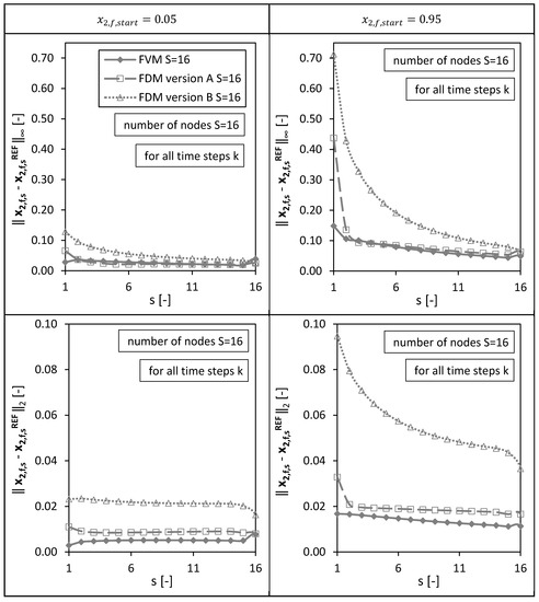
Figure 5.
Spatial l∞ and l2 error distribution calculated for all drying time steps k for the FVM, FDM version A and B using = 0.05 (left panels) and = 0.95 (right panels). Calculation settings: N = 26, S = 16, SREF = 64, Δt = 0.05 s (for FVM, FDM version A and B).
To be able to compare the molar fractions on coarse meshes with the fine reference solution , the molar fractions on the finer reference mesh were interpolated to the coarse grid. The deviations from the reference solution were calculated for each time step and for each spatial step . Thus, the following mole fraction vector was defined to calculate the and errors:
Figure 5 shows the resulting and errors calculated at each single node for all time steps (as example for a total amount of nodes). The error depicts the maximum value of the absolute error, the error corresponds to the norm of the error.
As observed already in Figure 4, the highest maximum absolute error ( error) at the last node for the case nodes and was given by the FVM due to the approximated boundary condition at . Nevertheless, the FVM shows small errors for all other nodes (similar to FDM version A) for both initial conditions (Figure 5). Overall, the smallest errors for all nodes (for all time steps and both initial conditions) were identified for the FVM. Version A of the FDMs shows generally smaller and errors compared to Version B (as already seen for the single node at the bottom of the packed bed (Figure 4)). For both errors, and , and all three numerical methods, the errors are generally higher for the initial condition compared to the case using due to an almost stepwise change of the molar fraction at the top of the packed bed () in the beginning of the drying process. The molar fraction changes here at the beginning of the drying process from nearly pure ethanol (component 2) to the autoclave entering pure CO2 (component 1). The errors are; therefore, higher at node compared to the other nodes.
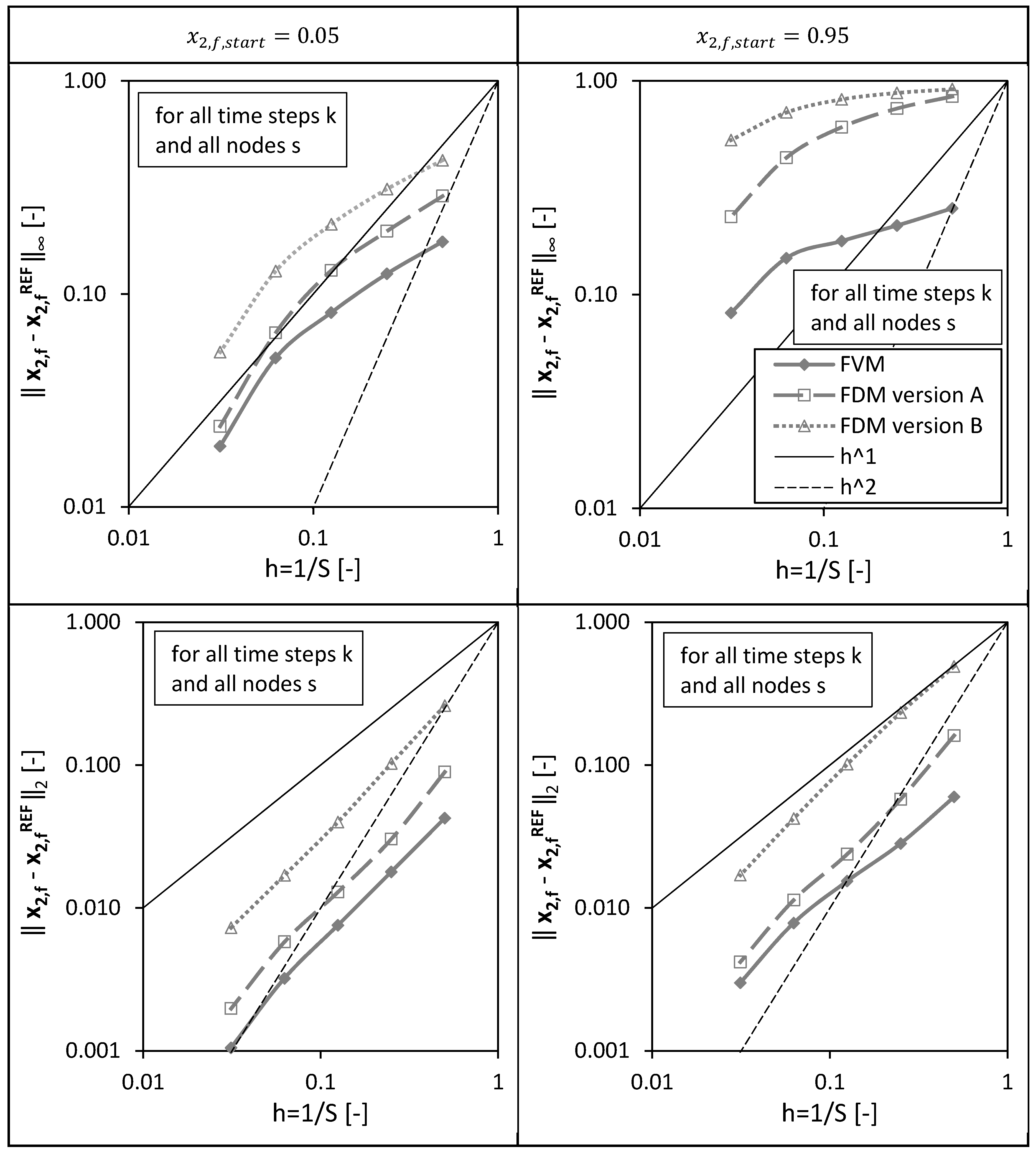
In a third step, the overall errors calculated for all spatial nodes of the packed bed height () and for all drying time steps () are presented in Figure 6 for different discretizations/grids () and both investigated initial conditions.
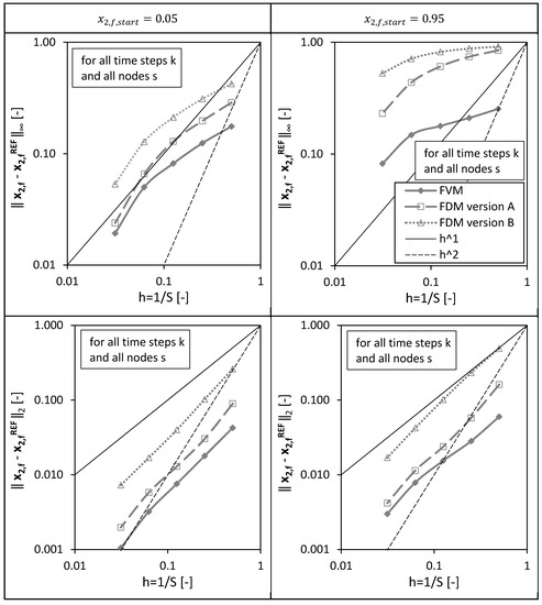
Figure 6.
Overall l∞ and l2 error calculated for all spatial nodes s and for all drying time steps k for the FVM, FDM version A and B using = 0.05 (left panels) and = 0.95 (right panels) depending on the reciprocal of the total number of nodes S. Calculation settings: N = 26, SREF = 64, Δt = 0.05 s (for FVM, FDM version A and B).
It is obvious that the overall errors are higher for the initial condition compared to the calculations using . For both initial conditions and both errors, and , the FVM shows the best convergence behavior, meaning the error decreases the fastest for an increasing total number of grid points (or smaller grid sizes ).
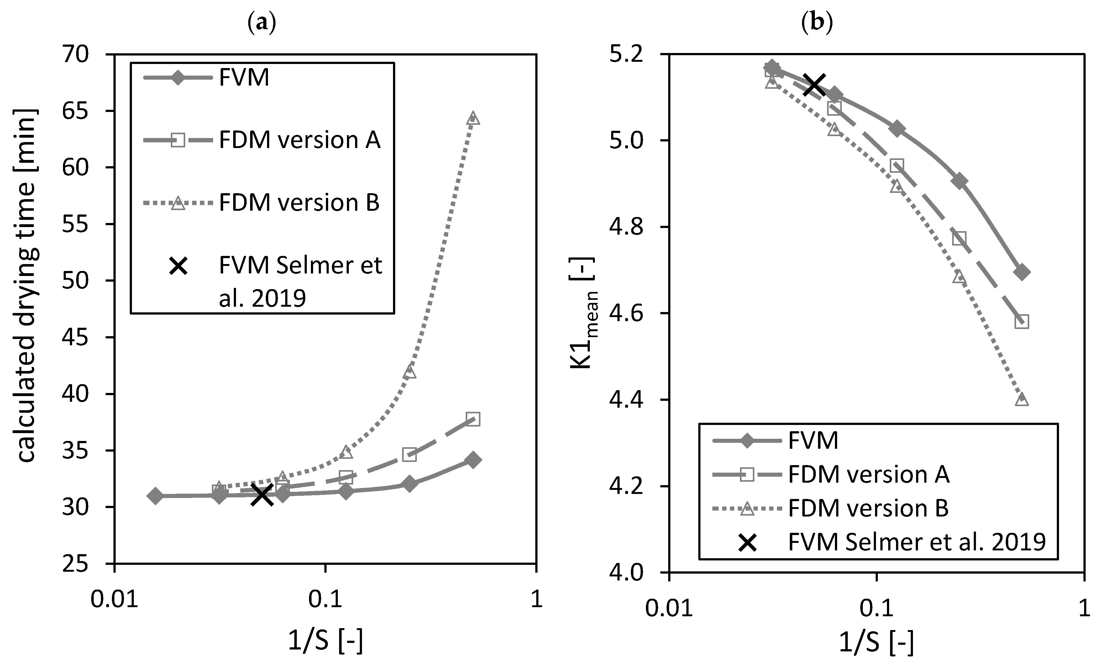
Next to the above analyzed molar fractions, the calculated drying times as well as the dimensionless number (both parameters were defined in the previously published paper [3]) are influenced by the total number of grid points in the region of packed bed (Figure 7). The calculated drying time is the time from start to end of the drying process, whereas the drying process ends when the ethanol molar fraction is less than within all gel particles of the packed bed [3]. depends slightly on the system temperature (see previously published paper [3]). The dimensionless number is a relative measure that shows which mass transport step is the limiting one for the overall drying kinetic, being either diffusion in the gel spheres or mass transport in the bulk fluid. It can be used to find a fast-drying process at low CO2 consumption [3].
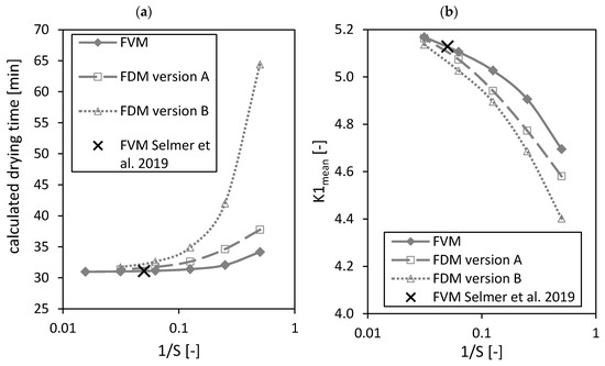
Figure 7.
Calculated drying time (a) and dimensionless number (b) calculated by the FVM, FDM version A and B and the FVM, with the settings used in Selmer et al. 2019 [3] depending on the reciprocal of the number of nodes S using = 0.05. Calculation settings: N = 26, SREF = 64, Δt = 0.05 s (for FVM, FDM version A and B), Δt = 0.1 s (for FVM Selmer et al. 2019 [3]), S = 20 (for FVM Selmer et al. 2019 [3]).
From Figure 7a it is obvious that a minimum can be reached for the calculated drying time by increasing the number of nodes . The black crosses in Figure 7 mark the settings of the FVM used in the previously published paper [3]. The calculated drying time from the previously published paper [3] is close to the found minimal value.
An increase of the total number of nodes leads to an increasing number (Figure 7b). The result of the previously published paper [3] is again close to the using the FVM and . Nevertheless, it is unclear if a maximum can be reached by increasing the total number of grid points further.
4.1.2. Mole Balances
During the drying process no chemical conversion occurs and thus the balance in terms of mole fraction of ethanol and carbon dioxide were considered. The closure of the mole balance of ethanol is shown in Figure 8 in the form of the relative error (Equation (52))
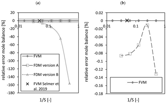
Figure 8.
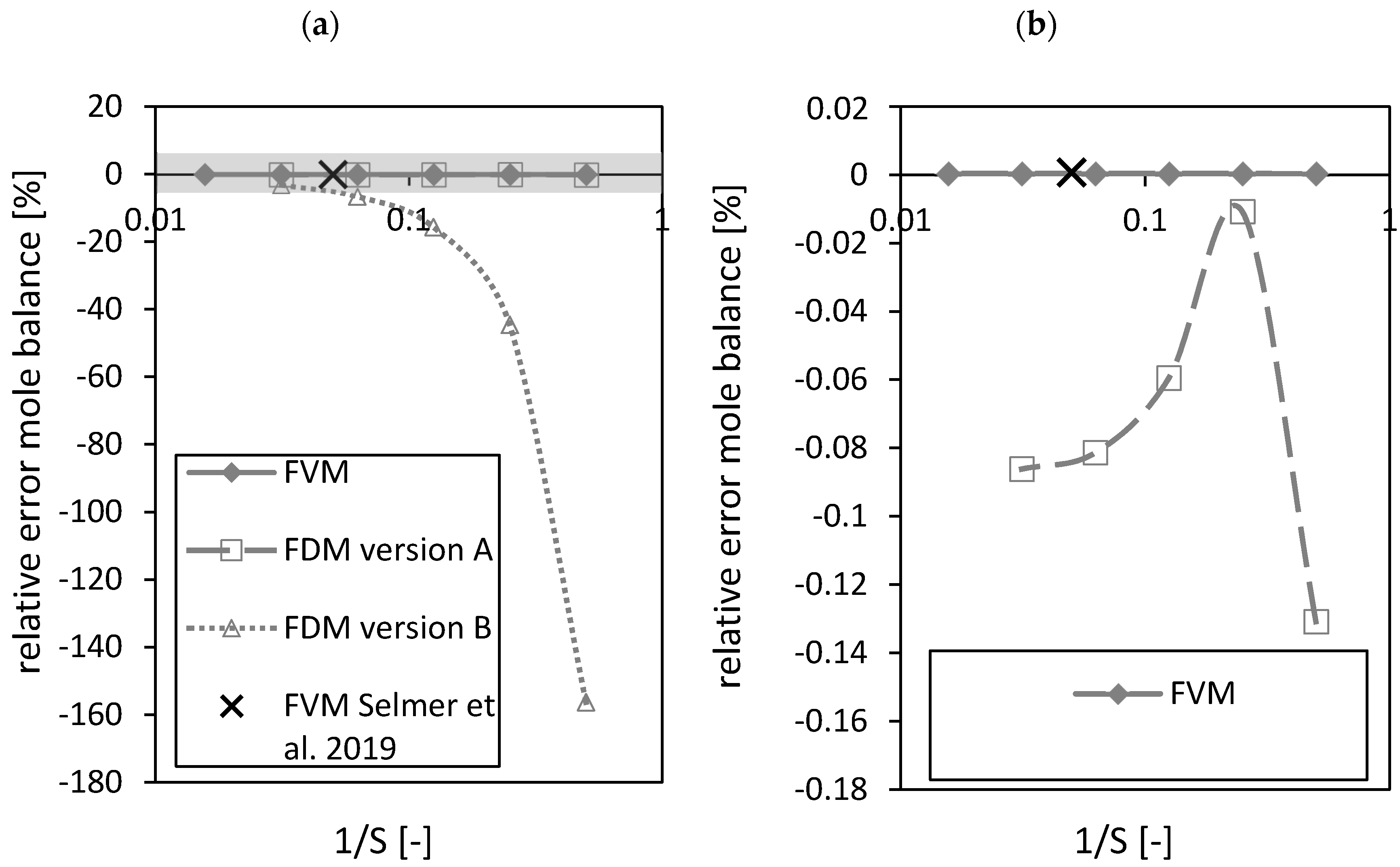
Relative error of the mole balance of the FVM, FDM version A and B and the FVM with the settings used in Selmer et al. 2019 [3] depending on the reciprocal of the number of nodes S using = 0.05 (a). Grey area is zoomed in on the right (b). Calculation settings: N = 26, SREF = 64, Δt = 0.05 s (for FVM, FDM version A and B), Δt = 0.1 s (for FVM Selmer et al. 2019 [3]), S = 20 (for FVM Selmer et al. 2019 [3]).
As expected, the FVM shows the best closure of the mole balance among all discretizations due to its requirement by definition to close the mass balance for each volume element (Figure 8a,b). The relative error of the FDM version A shows a better closure of the mass balance compared to FDM version B (Figure 8a). A maximum (corresponding to an absolute error minimum) was observed for the FDM version A (Figure 8b). The black crosses in Figure 8 mark the settings of the FVM used in the previously published paper [3]. Similar results for the relative errors of the FVM in both studies using different and total number of nodes were obtained. The relative errors of the FVM (expressed in %) were in the range of 10−4.
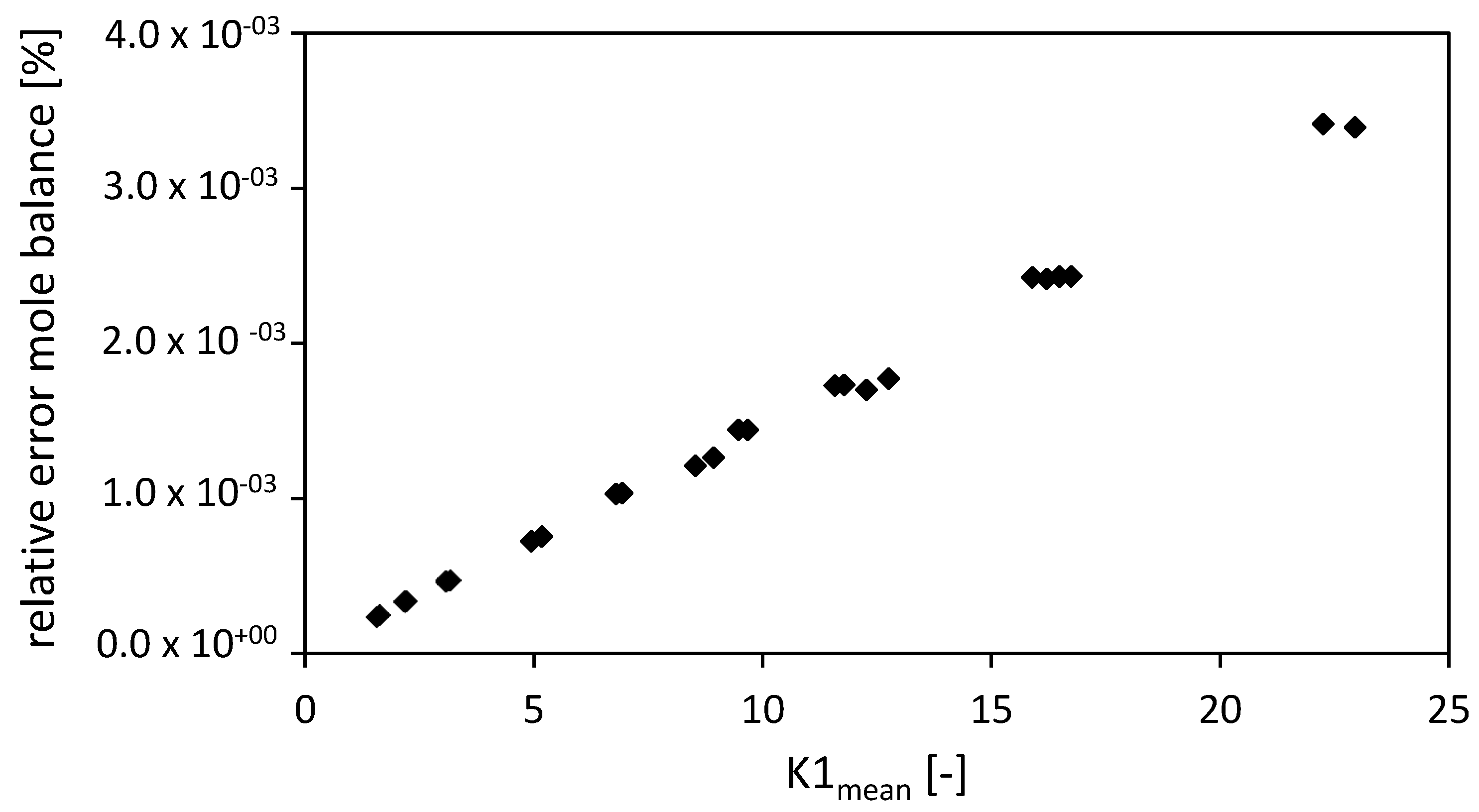
Comparing the closure of the mole balance of the FVM (for fixed and total number of nodes ) depending on the dimensionless number (Figure 9) shows that the relative error is increasing almost linearly with increasing dimensionless number . An increasing dimensionless number stands for an increased convective term in the packed bed [3].
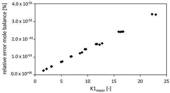
Figure 9.
Relative error of the mole balance of the FVM with the settings used in Selmer et al. 2019 [3] depending on the dimensionless number . Drying conditions: P = 9–17 MPa, T = 315–326 K, R = 3.175 mm, gel porosity = 0.93, gel tortuosity = 3.48, = 1, = f(T), bed porosity = 0.4, volume packed bed = 1.514 × 10⁻⁴ m3, diameter packed bed = 2.1 × 10⁻² m, = 0.05. Calculation settings: N = 26, Δt = 0.1 s, S = 20.
For a constant total number of nodes , an increase of the time step leads to an almost linear increasing relative error (not shown in the diagrams).
Summarizing, the FVM shows the highest approximation quality except for a sharp increase of the molar fraction at the bottom of the bulk fluid (). Version A of the FDM allows for more accurate calculations compared to version B and should be preferred when choosing the FDM.
4.2. Efficiency
4.2.1. Condition Numbers
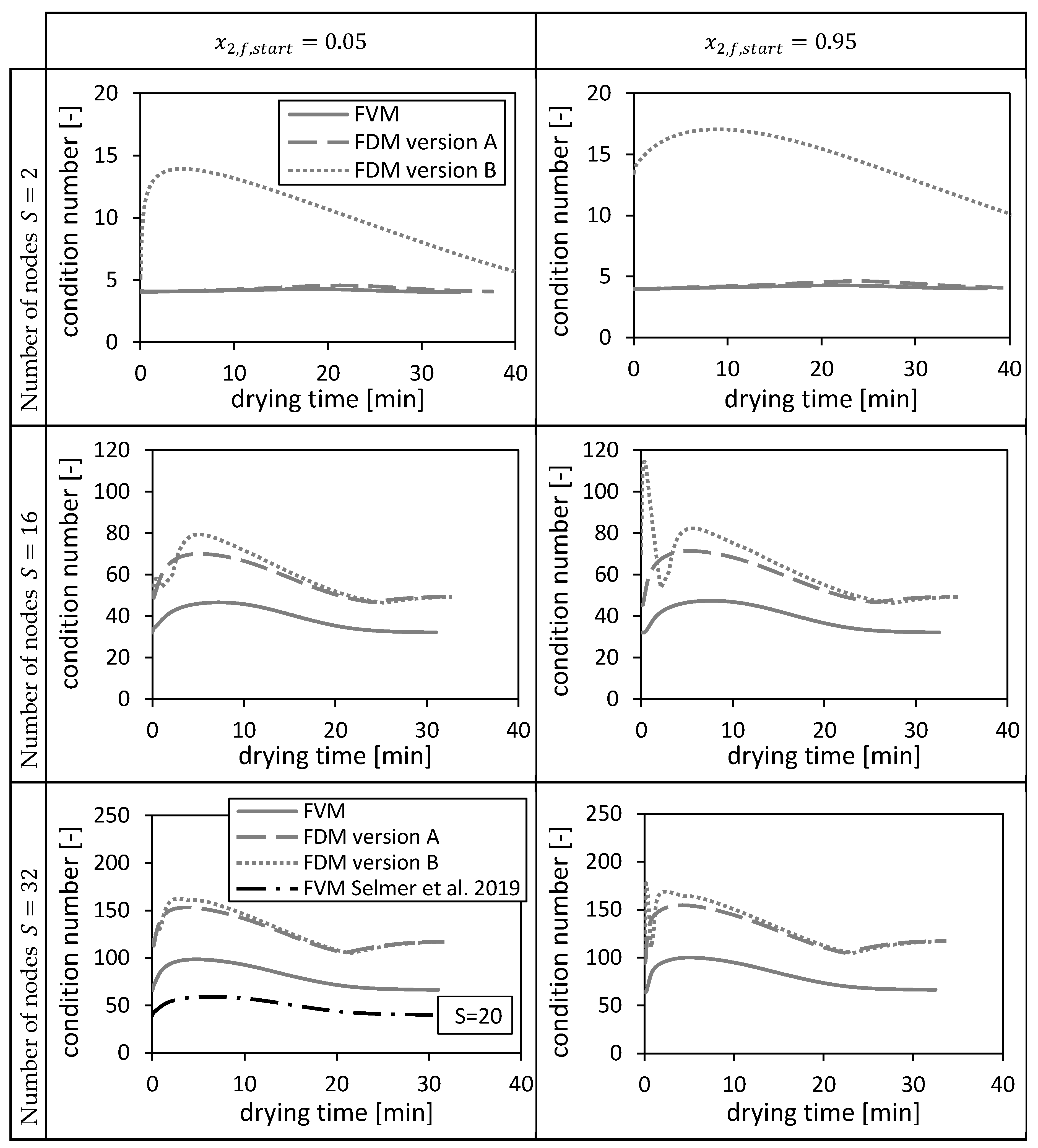
The condition numbers of (Equation (48), Equation (49)) and (version A and B, Equation (31), Equation (32)) are shown in Figure 10 corresponding to each numerical method for two different initial conditions (cf. Section 4.1.1.). The condition numbers vary with the drying time due to varying dispersion coefficients and interstitial velocities (Equation (31)/Equation (32), Equation (48)/Equation (49)). The condition number of the FVM is the lowest, whereas the condition numbers of the FDMs become closer to each other for increasing number of nodes. The condition number of the FDM version B is up to more than four times higher than the other condition numbers on coarse grids. Additionally, it fluctuates in the beginning of the drying process. The condition number of the FVM used in Selmer et al. 2019 [3] with nodes is between the condition numbers at and of the FVM. The condition number of FDM version B is more sensitive to the initial condition than the condition numbers of the other two methods.
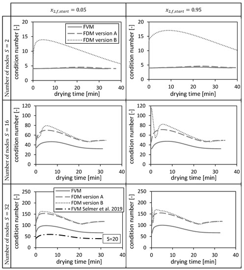
Figure 10.
Condition numbers of and (version A and B) corresponding to the FVM, FDM version A and B and the FVM, with the settings used in Selmer et al. 2019 [3], using = 0.05 (left panels) and = 0.95 (right panels) depending on the drying time and the number of nodes S. Calculation settings: N = 26, SREF = 64, Δt = 0.05 s (for FVM, FDM version A and B), Δt = 0.1 s (for FVM Selmer et al. 2019 [3]), S = 20 (for FVM Selmer et al. 2019 [3]).
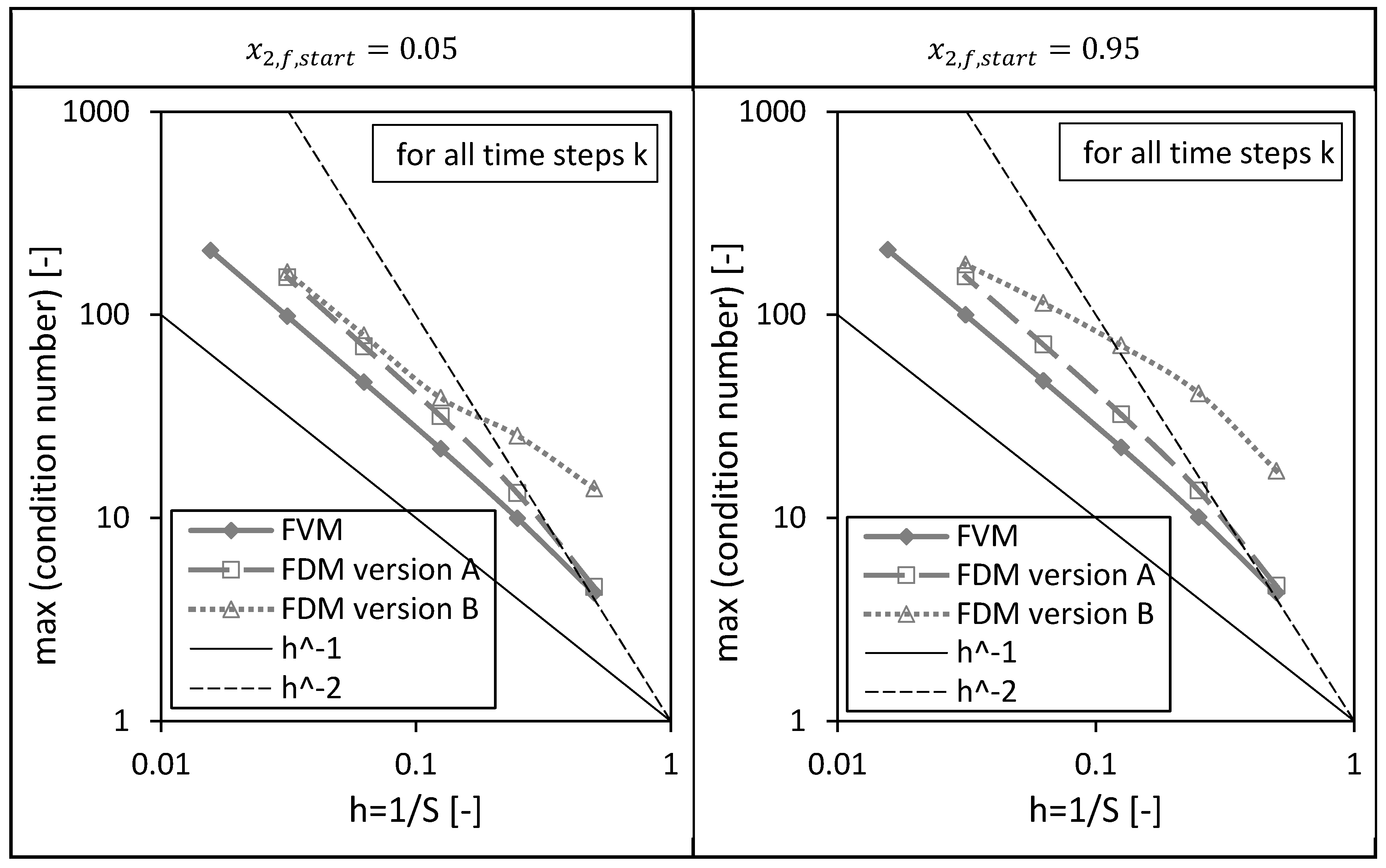
Next to the above presented drying time dependencies of the condition numbers, the corresponding maxima of the condition numbers are shown as a function of the reciprocal of number of nodes in Figure 11. The previously discussed results can be easily rediscovered here: The FVM has the lowest maximal condition numbers, the maximum condition numbers of all investigated numerical methods increase with increasing number of nodes or decreasing grid sizes and the condition number of the FDM version B is most sensitive with respect to the initial condition.
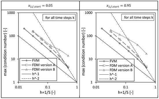
Figure 11.
Maximum of the condition numbers of and (version A and B) corresponding to the FVM, FDM version A and B using = 0.05 (left panel) and = 0.95 (right panel) depending on the reciprocal of the number of nodes S. Calculation settings: N = 26, SREF = 64, Δt = 0.05 s (for FVM, FDM version A and B).
4.2.2. Computation Time
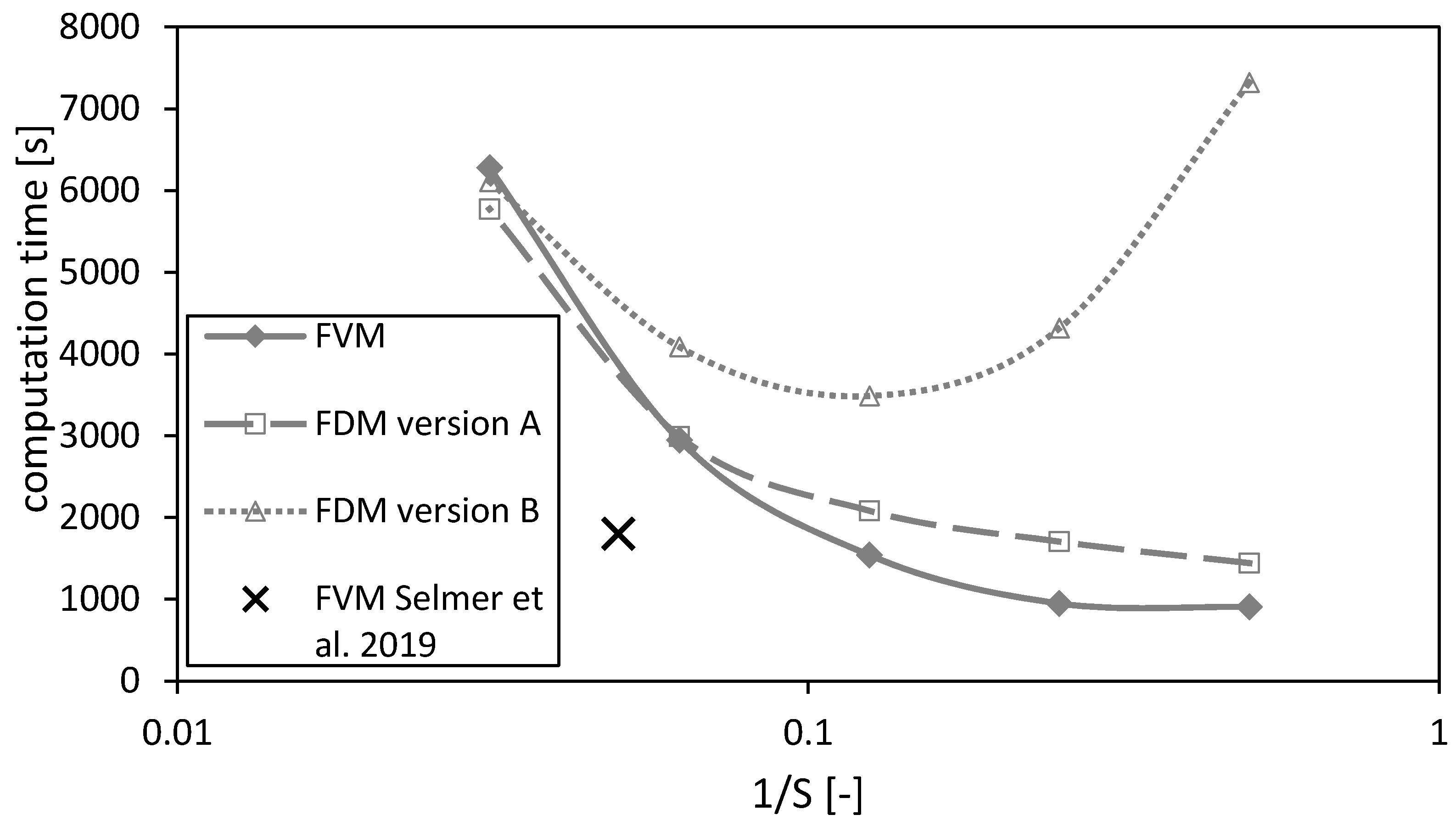
The computation time as a function of the reciprocal number of nodes is shown in Figure 12. In principal, the computation time increases for decreasing mesh sizes (or increasing number of nodes ) for all three methods. The calculations using the FVM take less time than using the FDMs (except on the finest mesh). Additionally, the calculation time increases for the FDM version B for coarse meshes due to an overestimation of the calculated drying time (Figure 7a) and thus longer calculation durations using a fixed time step. Hence, a minimum in the calculation duration of FDM version B can be observed in Figure 12.
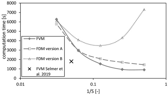
Figure 12.
Computation times of the FVM, FDM version A and B and the FVM, with the settings used in Selmer et al. 2019 [3] as function of the reciprocal of the number of nodes S, using = 0.05. Calculation settings: N = 26, SREF = 64, Δt = 0.05 s (for FVM, FDM version A and B), Δt = 0.1 s (for FVM Selmer et al. 2019 [3]), S = 20 (for FVM Selmer et al. 2019 [3]).
The black cross marks the settings of the previously published paper [3]. Its value is smaller than for the calculations of this paper due to a time step which is twice the time step of the calculations made here. Even though the time step is doubled for the calculations in Selmer et al. 2019 [3], the calculation quality is acceptable as shown in the previous sections.
5. Conclusions
In this work, we evaluated three different numerical methods, based on finite differences and finite volumes methods, to solve the advection diffusion equation arising in the context of the supercritical drying process of spherical gel particles in a packed bed.
The FVM showed the best closure of the mole balance, best convergence behavior and lowest condition numbers. Therefore, this method is recommended to solve the coupled partial differential equations describing the supercritical drying kinetic in a packed bed developed in Selmer et al. 2018 [2]. A sufficient number of nodes is needed especially for high temporal changes of the molar fractions in the bulk fluid. The reason is that high spatial and/or temporal changes of the molar fractions result into high variations of the physical mixture properties and thus changes all particular mass transfer steps directly or indirectly. Especially the effective diffusion coefficient within the porous gel particle, the mass transfer coefficient and the interstitial fluid velocity within the packed bed are influenced. More detailed information is given in [2,3].
The FDM version A showed good accuracy and computational efficiency. It is easy to implement and should be used with a sufficient number of nodes.
The FDM version B showed the lowest accuracy and efficiency. Thus, it is not recommended to be used.
Supplementary Materials
The underlying MATLAB codes are available online at https://doi.org/10.6084/m9.figshare.12504863 to provide all necessary details for the implementation of the algorithms presented in the paper.
Author Contributions
Conceptualization, I.S. (Ilka Selmer) and P.F.; methodology, I.S. (Ilka Selmer) and P.F.; software, I.S. (Ilka Selmer) and P.F.; validation, I.S. (Ilka Selmer) and P.F.; formal analysis, I.S. (Ilka Selmer) and P.F.; investigation, I.S. (Ilka Selmer); resources, P.G. and I.S. (Irina Smirnova); data curation, I.S. (Ilka Selmer); writing—original draft preparation, I.S. (Ilka Selmer); writing—review and editing, P.F., P.G. and I.S. (Irina Smirnova); visualization, I.S. (Ilka Selmer) and P.F.; supervision, P.G. and I.S. (Irina Smirnova); project administration, P.G.; funding acquisition, I.S. (Irina Smirnova). All authors have read and agreed to the published version of the manuscript.
Funding
This IGF Project AiF 17485 N of the FEI was supported via AiF within the program for promoting the Industrial Collective Research (IGF) of the German Ministry of Economic Affairs and Energy (BMWi), based on a resolution of the German Parliament. Ilka Selmer was supported by a scholarship of Pro Exzellenzia.
Acknowledgments
We would like to thank Anna-Sophia Behnecke for developing the code for the computation of the diffusion within the porous gel spheres.
Conflicts of Interest
The authors declare no conflict of interest. The funders had no role in the design of the study; in the collection, analyses, or interpretation of data; in the writing of the manuscript, or in the decision to publish the results.
Nomenclature
| Cross-sectional area of the cylindrical autoclave | ||
| Row vector in finite volume matrix | ||
| Row vector in finite difference matrix | ||
| Finite volume method matrix | ||
| Finite difference method matrix | ||
| Surface area of the spherical particle | ||
| Bernoulli function | ||
| Right-hand side vector for finite volume method | ||
| Right-hand side vector for finite difference method | ||
| Concentration | ||
| Ethanol concentration in the bulk fluid | ||
| Vector ethanol concentration of the axial bulk fluid elements | ||
| Ethanol concentration within the porous gel particle | ||
| Mixture concentration in the bulk fluid | ||
| Mixture concentration within the porous gel particle | ||
| Diffusion coefficient | ||
| Axial dispersion coefficient in the packed bed | ||
| Effective diffusion coefficient within the porous gel particle | ||
| Function | ||
| Flux of ethanol | ||
| Dimensionless grid size | ||
| Time index | ||
| Number of time steps | ||
| Dimensionless number | ||
| Length of the packed bed | ||
| Euclidean norm | ||
| Maximum norm | ||
| Mass flowrate of the ethanol–CO2 mixture | ||
| Maximum | ||
| Radial index in gel particle domain | ||
| Number of nodes in gel particle domain | ||
| End mole number of ethanol | ||
| Start mole number of ethanol | ||
| Number of particles | ||
| Pressure | ||
| Numerical Péclet number | ||
| Radial coordinate of the spherical particle | ||
| Particle radius | ||
| Axial index in autoclave/bulk fluid domain | ||
| Number of nodes in autoclave/bulk fluid domain | ||
| Ethanol source term within the bulk fluid | ||
| Time | ||
| Temperature | ||
| Interstitial fluid velocity | ||
| Superficial fluid velocity | ||
| Volume flow | ||
| Function | ||
| Volume bulk fluid | ||
| Volume element of spherical gel particle | ||
| Ethanol molar fraction in the bulk fluid | ||
| Vector ethanol molar fraction of the axial bulk fluid elements and time indices | ||
| Reference vector ethanol molar fraction of the axial bulk fluid elements and time indices | ||
| Vector ethanol molar fraction of the time indices | ||
| Ethanol molar fraction within the porous particle | ||
| Molar fraction of component i | ||
| Node | ||
| Cell interface | ||
| Axial coordinate of the autoclave/packed bed | ||
| Greek letters | ||
| Mass transfer coefficient | ||
| Distance between neighboring nodes in gel particles | ||
| Time step | ||
| Distance between neighboring nodes in autoclave/bulk fluid domain | ||
| Length of volume element | ||
| Vector lengths of volume elements | ||
| (Aero)gel particle porosity | ||
| Porosity of the packed bed (spherical porous particles are here assumed to be nonporous) | ||
| Density of ethanol-CO2 mixture in the bulk fluid | ||
| Tortuosity within the porous gel particle | ||
| Super and subscripts | ||
| Start | ||
| Component carbon dioxide | ||
| Component ethanol | ||
| Autoclave | ||
| Complete flux scheme | ||
| Carbon dioxide | ||
| End | ||
| Ethanol | ||
| Bulk fluid | ||
| Finite difference method | ||
| Finite volume method | ||
| Gel | ||
| Homogenous | ||
| Substance component i | ||
| , | Inhomogeneous | |
| Time index | ||
| Number of time steps | ||
| Radial index in gel particle domain | ||
| Particle | ||
| Reference | ||
| Axial index in autoclave/bulk fluid domain | ||
| Number of nodes in autoclave/bulk fluid domain | ||
| Transposed |
References
- Şahin, İ.; Özbakır, Y.; İnönü, Z.; Ulker, Z.; Erkey, C. Kinetics of Supercritical Drying of Gels. Gels 2018, 4, 3. [Google Scholar] [CrossRef] [PubMed]
- Selmer, I.; Behnecke, A.-S.; Quiño, J.; Braeuer, A.S.; Gurikov, P.; Smirnova, I. Model development for sc-drying kinetics of aerogels: Part 1. J. Supercrit. Fluids 2018, 140, 415–430. [Google Scholar] [CrossRef]
- Selmer, I.; Behnecke, A.-S.; Farrell, P.; Morales, A.B.; Gurikov, P.; Smirnova, I. Model development for sc-drying kinetics of aerogels: Part 2. J. Supercrit. Fluids 2019, 147, 149–161. [Google Scholar] [CrossRef]
- Şahin, İ.; Uzunlar, E.; Erkey, C. Investigation of kinetics of supercritical drying of alginate alcogel particles. J. Supercrit. Fluids 2019, 146, 78–88. [Google Scholar] [CrossRef]
- Şahin, İ.; Uzunlar, E.; Erkey, C. Investigation of the effect of gel properties on supercritical drying kinetics of ionotropic alginate gel particles. J. Supercrit. Fluids 2019, 152, 104571. [Google Scholar] [CrossRef]
- Hatami, T.; Viganó, J.; Innocentini Mei, L.H.; Martínez, J. Production of alginate-based aerogel particles using supercritical drying: Experiment, comprehensive mathematical model, and optimization. J. Supercrit. Fluids 2020, 160, 104791. [Google Scholar] [CrossRef]
- Santos, P.d.; Viganó, J.; Furtado, G.d.F.; Cunha, R.L.; Hubinger, M.D.; Rezende, C.A.; Martínez, J. Production of resveratrol loaded alginate aerogel: Characterization, mathematical modeling, and study of impregnation. J. Supercrit. Fluids 2020, 163, 104882. [Google Scholar] [CrossRef]
- Forsythe, G.E.; Wasow, W.R. Finite Difference Methods for Partial Differential Equations; Wiley: New York, NY, USA, 1960. [Google Scholar]
- Morton, K.W.; Mayers, D.F. Numerical Solution of Partial Differential Equations; Cambridge University Press: Cambridge, UK, 2005. [Google Scholar]
- Eymard, R.; Gallouët, T.; Herbin, R. Finite volume methods. In Solution of Equations in R^n (Part 3), Techniques of Scientific Computing (Part 3); Ciarlet, P.G., Lions, J.L., Eds.; Elsevier: Amsterdam, The Netherlands, 2000; Volume 7, pp. 713–1018. [Google Scholar] [CrossRef]
- Farrell, P.; Linke, A. Uniform Second Order Convergence of a Complete Flux Scheme on Unstructured 1D Grids for a Singularly Perturbed Advection–Diffusion Equation and Some Multidimensional Extensions. J. Sci. Comput. 2017, 72, 373–395. [Google Scholar] [CrossRef]
- Danckwerts, P.V. Continuous flow systems. Chem. Eng. Sci. 1953, 2, 1–13. [Google Scholar] [CrossRef]
- Si, H.; Gärtner, K.; Fuhrmann, J. Boundary conforming Delaunay mesh generation. Comput. Math. Math. Phys. 2010, 50, 38–53. [Google Scholar] [CrossRef]
- Thiart, G.D. Improved Finite-Difference Scheme for the Solution of Convection-Diffusion Problems with Simplen Algorithm. Numer. Heat Transfer Part B Fundamentals 1990, 18, 81–95. [Google Scholar] [CrossRef]
- Ten Thije Boonkkamp, J.H.M.; Anthonissen, M.J.H. The Finite Volume-Complete Flux Scheme for Advection-Diffusion-Reaction Equations. J. Sci. Comput. 2011, 46, 47–70. [Google Scholar] [CrossRef]
- Ten Thije Boonkkamp, J.H.M.; Schilders, W.H.A. An exponential fitting scheme for the electrothermal device equations, specially for the simulation of avalanche generation. COMPEL Int. J. Comput. Math. Electr. Electron. Eng. 1993, 12, 95–111. [Google Scholar] [CrossRef]
Publisher’s Note: MDPI stays neutral with regard to jurisdictional claims in published maps and institutional affiliations. |
© 2020 by the authors. Licensee MDPI, Basel, Switzerland. This article is an open access article distributed under the terms and conditions of the Creative Commons Attribution (CC BY) license (http://creativecommons.org/licenses/by/4.0/).

