1. Introduction
Structural color is generated from the interaction between incident light and the periodic structure of photonic crystals. According to Bragg diffraction, the wavelength of structural color is related to the effective refractive index, the lattice parameter, and the diffraction angle [
1,
2,
3]. The angle dependence of structural colors is important for some applications, such as in aesthetics and decoration and anti-counterfeiting [
4]. However, angle-dependence is restricted in its application in fields, such as display and military stealth, that require color to remain unchanged over a large range of viewing angles. Therefore, the preparation of quasi-amorphous photonic crystal materials is an important way to broaden their application [
5,
6]. Harun-Ur-Rashid et al. fabricated SiO
2 amorphous arrays, and its structural color essentially remained unchanged from 0° to 40°, which shows angle-independence [
7]. Meng et al. synthesized polystyrene (PS) non-iridescent structural color films with high hydrophobicity and good mechanical stability through chaotic convective co-assembly. The structural color remained essentially unchanged in observation angle ranges of 0°–60°. With the help of carbon black, the color saturation was enhanced due to light absorption characteristic [
8].
Responsive photonic crystals can respond to external stimuli through the visible changes of structural color [
9,
10]. They are widely used in color displays, ink-free rewritable paper [
11,
12], anti-military camouflage [
13], information security [
14,
15] and biochemical sensors [
16,
17]. Electrically tunable photonic crystals are obtained through constructing electrochromic materials into photonic crystals, which can respond to external electric field stimulation through structural color changes due to volume expansion or contraction. Qu et al. obtained a lamellar PANI/PS-b-P2VP thin film which can provide an ideal multicolored electrochromic platform via spin-coating. The structural colors are widely controlled under a small electrical bias via the reversible change in the composition and domain spacing [
18]. Yue et al. fabricated one-dimensional photonic crystals formed by ultrahigh-water-content polyelectrolyte layered hydrogels, and its structural colors are tunable to versatile colors when an electric field is applied [
19]. Lee et al. synthesized an electrically tunable inverse opal photonic gel, and the structural colors are angle-dependent [
20]. Although electrically tunable photonic crystals have been widely studied, there are few reports on angle-independent inverse opal photonic crystals, which have great applicability prospects in display and military stealth.
In this study, we produced an electrically tunable multi-color display angle-independent inverse opal photonic gel (IOPG). The long-term disordered opal template was used as a template, which was obtained through the simple chaotic convective flow assembly method. The precursor consisted of hydroxyethyl methacrylate (HEMA), and ionizable monomer acrylic acid (AA) was photopolymerized with the help of a “sandwich” structure of the template. After etching, the angle-independent inverse opal photonic gel (AA-IOPG) was obtained, and it can respond to electrical stimulation through changes in structural colors. The disordered AA-IOPG shows the characteristics of high color tunability and durability through repeated opposite bias voltage tests. We propose a novel design scheme for the study of angle-independent electrically tunable inverse opal photonic gel and achieve a tunable multi-color display. The AA-IOPG is a promising conductive photonic material and this work can lay the foundation for its application in the field of dynamic display.
2. Results and Discussion
A key procedure in the preparation of angle-independent inverse opal photonic gel film is the preparation of an angle-independent photonic crystal template. We adopt the method of horizontal growth micro-disturbance assembly, select the double-sided tissue paper composed of fiber and a porous surface (
Figure S4) and overlay assembly to construct the template of an amorphous structure. Acrylic hydrogel electroactive material was further constructed based on the template. Under the action of applied voltage, the inverse opal micropore structure becomes larger or smaller, causing the hydrogel film to expand or contract and subsequently resulting in different angle-independent structural colors on the macro level.
Figure 1 shows the specific preparation steps. Droplets of PS microsphere (193 nm in diameter) doped with trace CB were dropped on the glass substrate, and the surface of the suspension was quickly covered with a piece of treated double-sided tissue paper and heated to 70 °C to assemble. When the double-sided tissue paper was detached from the surface of the mixture, a blue disordered PS template could be obtained. The template was filled with the pre-polymer solution and placed under a UV lamp for photopolymerization. After soaking in tetrahydrofuran to remove PS microspheres, the green acrylic inverse opal photonic gel electroactive material was obtained. The ITO glass was used to construct a sandwich device. Since the light blue color of the ITO glass might affect the spectrum test, the upper layer of the ITO glass was replaced with acrylic glass attached to double-sided conductive copper foil in the actual test. By using physical pressing, the gel film was fixed on to the bottom ITO glass through the sealing film and connected to the positive electrode of the constant current power supply. In the phosphate electrolyte environment of 10
−3 M and pH = 7, with the application of 4 V voltage, the structural color of the hydrogel film is slightly blueshifted, showing a blue-green macro color. With the application of −4 V voltage, the structural color of the hydrogel film is redshifted, and the macro color is orange-yellow.
According to the SEM image, it can be seen that the assembled disordered template PS microsphere is uniform in size, with a calculated diameter of about 193 nm. The disordered template is a short-range ordered and long-range disordered structure, as shown in
Figure 2a,b. Such a structure is spatially isotropic, and the refractive index difference inside is the same in all directions. When the size of the structural unit is consistent with the wavelength of visible light, a photonic band gap is generated. In the amorphous structure, the position of the photonic band gap is not affected by the direction of the incident light, so the structural color is angle-independent [
21,
22]. It can be seen that there are smaller conductive carbon black particles, which could absorb incident photons, reducing the propagation path of light in the template, thereby reducing the overall scattering intensity, making the scattering effect of the structural color wavelength become prominent and improving color saturation [
23,
24]. As shown in
Figure 2c, the surface of the disordered AA-IOPG organic film contains a large number of irregular porous structures, including both large pores (~1 um) and small pores (~200 nm), and the large pores contain many small holes which were formed by the etching of the disordered template. The side face SEM images were obtained by cutting the sample, as shown in
Figure 2d; the organic film has a disordered inverse opal structure inside, and the pore size of a single pore is about 200 nm. The thickness of the film is about 105 μm (
Figure S5). Because of this disordered inverse opal structure, the organic film shows a single, angle-independent structural color on the macro level.
In order to demonstrate the angle-independent property of the opal photonic crystal templates and the corresponding anti-opal photonic gels, the optical photos taken with digital cameras from different angles are observed. It can be seen that when the tilt angle is 80° and below, the structural color is almost unchanged (
Figure 3a,b). The reflectance spectral data are in good agreement with the experimental results obtained from optical photographs (
Figure 3c,d). Due to the limitation of experimental instruments, the diffuse reflection signals were achieved by changing the tilt angles of the probe, so when the test angle is large, the obtained spectral data reflectivity is very weak; that is because the probe can only receive limited light source signals. It can be shown that the opal photonic crystal templates and the corresponding anti-opal photonic gels are angle-independent.
Another crucial test is the electrical response of the disordered AA-IOPG. The variation of reflection spectra over time in the vertical direction (0°) and tilt 12° with ±4 V bias voltages are shown in
Figure 4. The reflection spectral data in the vertical direction (0°) are shown in
Figure 4a. At the beginning of the test, the voltage is adjusted to 0 V, and the circuit is turned on to form a closed loop for 120 s to eliminate the effect of the potential. After applying 4 V voltage for 120 s, the maximum reflective peak wavelength λ
max blueshifts from 540 nm to 510 nm (
Figure 4b), and the macro structural color changes from green to blue-green. This is probably because H
+ is generated from the water decomposing on the surface of the ITO conductive glass at the anode and the local pH value decreases, and then the—COO
− groups of the AA-IOPG tend to protonate to form—COOH and migrate to the anode, resulting in the decrease of pore size, lattice spacing d and λ
max of the gel film, so the structural color blueshifts (
Figure 5), which is consistent with the previous report [
20]. When the voltage is adjusted to 0 V for 120 s, the hydrogel recovers slowly, with a slight redshift, and the macroscopic structural color is essentially unchanged, mainly because the pH value of the environment where the AA-IOPG is essentially unchanged and the only recovery force depends on the elastic of the gel film itself. The color change is shown in
Figure 6a.
Then the −4 V voltage is applied and maintained for 120 s. The maximum reflection peak is redshifted to 620 nm, and the macro structural color changes from green to orange-yellow because H
+ on the surface of the ITO conductive glass makes electrons form H
2 at the cathode. The rapid consumption of H
+ leads to an increase in the local pH value, and the—COO
− group of the AA-IOPG repulse the cathode and migrate to the anode. As a result, the pore size, the lattice spacing d and λ
max of the gel film are enlarged, and the structural color is redshifted (
Figure 5). When the voltage is adjusted to 0 V again and maintained for 120 s, the hydrogel recovers slowly, slightly blueshifts, and the macro structural color is still orange-yellow. The chromaticity coordinates of the AA-IOPG changed from CIE: (0.424, 0.507) under 0 V to (0.358, 0.488) under +4 V and to (0.440, 0.444) under −4 V in the vertical direction (0°), as shown in
Figure 4c.
The variation of the reflection spectrum data results in the tilt direction (12°) is the same as that measured in the vertical direction, as shown in
Figure 4d,e, and the corresponding optical photo changes are also consistent. As shown in
Figure 6b, the macro structural color can change from green to blue-green and then to orange-yellow. The chromaticity coordinates of the AA-IOPG changed from CIE: (0.351, 0.451) under 0 V to (0.307, 0.425) under +4 V and to (0.394, 0.424) under −4 V in the tilt direction (12°), as shown in
Figure 4f. The variation of the reflection spectra over time in other tilt angles are shown in
Figure S6. These results indicate that acrylic hydrogels with an inverse opal structure can achieve angle-independent color conversion under electrical stimulation.
The acrylic inverse opal photonic gel film has good durability.
Figure 7 shows the peak wavelength changes of the disordered AA-IOPG under different voltages originally and after six months. A test cycle starts from a positive voltage and turn-off voltage to a negative voltage and turn-off voltage. The corresponding spectral maximum reflectance peak is first blueshifted and then redshifted. After six months, the AA-IOPG film exhibits the same performance, proving its good durability (
Figure S7). When the tested gel film is placed in a phosphate electrolyte of 10
−3 M and pH = 7, the gel film can quickly return to its initial state. However, the ITO conductive glass used in the test would be oxidized at 4 V voltage, so the second cycle test should change the ITO glass to form another device using the same gel film. After several tests, the gel film still maintains good optical properties only if there is enough aqueous solution for supplying or consuming H
+.
4. Materials and Methods
4.1. Materials
Styrene (GC ≥ 99.5%), potassium persulfate (KPS) and sodium dodecyl sulfate (SDS) were purchased from Sinopharm Chemical Reagent Co., Ltd., Shanghai, China, and used to synthesize polystyrene (PS) microspheres. Hydroxymethyl methacrylate (HEMA) purchased from Sigma-Aldrich, St. Louis, MO, USA; ethylene glycol dimethacrylate (EGDMA, GC = 98%) purchased from J&K Scientific, San Jose, CA, USA; and acrylic acid (AA, GC ≥ 98%) and Irgacure1 (photoinitiator, GC = 99%) purchased from Adamas-beta® Inc., Shanghai, China, were used to prepare photonic gel monomers. Deionized (DI) water was prepared using a laboratory water purification system. Different amounts of Na2HPO4 (Sinopharm Group, Shanghai, China) and NaH2PO4 (Sinopharm Group) were dissolved in deionized water, and phosphate buffers with different pH values were calculated. Conductive carbon black (CB, ~23 nm) was purchased from Jiangsu XFNANO Materials Tech Co., Ltd., and was added in small amounts to enhance the color saturation of the template. A black long-tail ticket holder (metal clip) and black insulation tape were purchased from Zhejiang Ninhai Deli Group Co., Ltd., Ningbo, China; the sealing film PM-996 was purchased from Parafilm Co., Ltd., Warrington, PA, USA; the double-sided tissue paper was purchased from Dongguan Blue Sky Paper Co., Ltd., Dongguan, China; the methyl silicone oil was purchased from Longxu (Shanghai, China) Organosilicone Technology Co., Ltd. Acrylic transparent organic glass (transmittance ≥ 92%) was purchased from Jiangxi Oujia Industry Co., Ltd., Fuzhou, China; indium tin oxide (ITO) conductive glass (square resistance ≤ 6 Ω, transmittance ≥ 84%, film thickness 185 nm, light blue) and double-sided conductive copper foil were purchased from South China Xiangcheng Technology Co., Ltd., Shenzhen, China. ITO conductive glass was used after ultrasonic cleaning with acetone, deionized water and anhydrous ethanol. Tetrahydrofuran (GC ≥ 99.5%), acetonitrile (GC ≥ 99.5%) and ethanol (GC ≥ 99.7%) were purchased from Sinopsin Chemical Reagent Co., Ltd., Shanghai, China, and used directly after receiving them.
4.2. Preparation of Disordered Template from Monodisperse Polystyrene Microspheres
Monodisperse polystyrene microspheres were prepared by emulsion polymerization using styrene as a monomer, sodium dodecyl sulfate as an emulsifier and potassium persulfate as an initiator. The emulsion with differently sized microspheres was obtained by adjusting the amount of emulsifier, as shown in
Table S1.
The specific method is as follows. A certain amount of sodium dodecyl sulfate and 135 mL deionized water was added to a 250 mL three-neck flask. After condensing in water and 300 r/min mechanical stirring for 15 min, 15 g styrene was added. After heating in an oil bath for 30 min at 85 °C, potassium persulfate (1 wt% of styrene) was added. The polystyrene (PS) microsphere emulsion was obtained after 5 h.
A total of 0.1 g conductive carbon black, 0.08 g SDS and 40 g DI Water were added into a beaker and mixed evenly by stirring and using ultrasonic waves to obtain a carbon black solution.
The monodisperse PS emulsion (PS particle concentration was 10 wt%) with different particle sizes was mixed with the carbon black solution (5 wt% of PS emulsion) and dispersed by ultrasonic waves for 30 min. The glass substrate was placed on a 70 °C heating plate, and an appropriate amount of the abovementioned mixture was dropped onto the glass substrate, and the treated double-sided tissue paper was immediately placed on the surface of the mixture. The double-sided tissue paper should be cut into the same size as the glass substrate before use, wiped with methyl silicone oil and dried. Through the pore evaporation guide of the two-sided tissue paper, the mixture particles underwent Brownian motion and assembled disorderly. When the double-sided tissue paper was removed from the surface of the mixture, the disordered PS template could be obtained. The SEM images and the optical photos of the templates are shown in
Figures S1 and S2.
4.3. Preparation of Disordered Inverse Opal Hydrogel Film
The as-assembled PS template was covered with a clean acrylic glass sheet and held with metal clips to form a sandwich.
The monomer mixture was prepared by mixing 2.5 g hydroxyethyl methacrylate (HEMA) as a hydrogel building block, 0.100 g ethylene glycol dimethacrylate (EGDMA) as a crosslinking agent, 0.075 g Irgacure1 as a photoinitiator, and 0.0346 g AA (2.5 mol% of HEMA) and 0.0625 g DI water. After filling the PS opal template with the monomer mixture for 10 min, photopolymerization was performed using a UV lamp (100 W, spectral line) for 2 h. After disassembly, the sample was immersed in tetrahydrofuran and extracted by a Soxhlet extractor for 2 days to completely remove the PS template.
After the template was removed, the prepared acrylate inverse opal photonic gel (AA-IOPG) film was rinsed with chloroform, acetonitrile and deionized water and finally immersed in an aqueous buffer solution. The optical photos of the AA-IOPG are shown in
Figure S3.
4.4. Fabrication of Sandwich Type Electrical Device
The acrylic glass and the ITO conductive glass were cut into a 2 cm × 2 cm size, and the ITO conductive glass was ultrasonically washed with acetone, DI water and ethanol. Double-sided conductive copper foil was adhered to the surface of the acrylic glass, leaving a square hole (6 mm × 12 mm) to facilitate the reflection spectrum test. The other side of the acrylic glass was covered with black insulation tape to isolate the influence of the copper foil’s color on the reflection spectrum test. The conductive copper foil surface of the acrylic glass was connected to the negative electrode of the constant current power supply as the cathode. The gel film was spread out and attached to the conductive layer of the bottom ITO conductive glass, which was connected to the positive electrode of the constant current power supply serving as the anode with double-sided conductive copper foil, and the sealing film was used to fix the gel film. A phosphate electrolyte of 10−3 M and pH = 7 was injected and the two electrodes were clamped with metal clips to form a sealed device. The sealing film acted as a spacer, and the spacing between the two electrodes was about 120 nm.
Continuous replenishment of the electrolyte to the device was required during the electrical structural colors tuning tests of the disordered AA-IOPG using a constant current power supply to apply a bias between the two electrodes.
4.5. Characterizations
The optical photos and videos were taken with a digital camera in professional mode. SEM images were taken with the Zeiss Sigma 300 SEM (Carl Zeiss AG, Oberkochen, Germany) and Hitachi Advanced Scanning Electron Microscope FlexSEM 1000 II (Hitachi Ltd., Tokyo, Japan), and all samples were sprayed with gold before testing. In addition, the disordered AA-IOPG gel film was treated with CO2 drying with the American Tousimis Samdri-PVT-3D (Tousimis Research Corporation, Rockville, MD, USA) critical point dryer before gold spraying. The applied voltage was provided by the constant current power supply of Nanjing NANDA Wanhe Technology Co., Ltd., Nanjing, China. The reflectance spectral data were provided by the USB2000+ FiberSpectrometer of the Marine Optical Miniature (Ocean Optics, Orlando, FL, USA), and the data for different angle tests were measured by tilting the probe and changing the angle to the normal of the sample.


 and
and 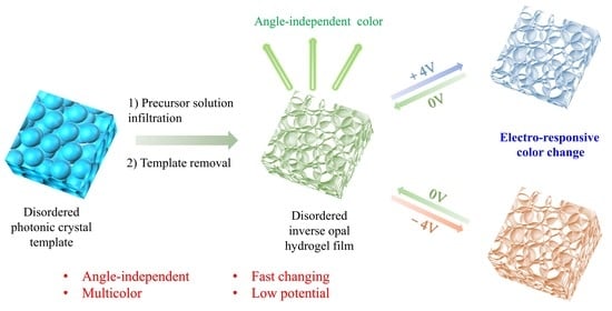


