Abstract
Membrane filtration fouling is a very complex process and is determined by many properties such as the membrane internal morphology, membrane pore structure, flow rate and contaminant properties. In a very slow filtration process or during the late stage of filtration, when the flow rate is naturally low and Péclet number is small, particle diffusion is essential and cannot be neglected, while in typical filtration models, especially in moderate and fast filtration process, the main contribution stems from the particle advection. The objectives of this study is to formulate mathematical models that can (i) investigate how filtration process varies under possible effects of particles diffusion; and (ii) describe how membrane morphology evolves and investigate the filtration performance during the filtration process. We also compare the results with the case that diffusion is less important and make a prediction about what kind of membrane filter pore structure should be employed to achieve a particular optimum filtration performance. According to our results, the filtrate and efficiency of particle separation are found to be under the trade-off relationship, and the selection of the membrane properties depends on the requirement of the filtration.
1. Introduction
Membrane filters are used in various industries and one of their most significant applications is water purification [1,2], where particles are removed from the water flow by applying micro-filtration. In particular, the reverse osmosis membrane is a great technique applied in water treatment [3]. Membrane filtration also exerts an important role in biotech industry in several aspects, for example, they are used in artificial kidneys for hemodialysis process [4]. Other applications include fruit juice processing [5], enhanced oil recovery [6], and recycling microorganism [7], among many others. Membrane filters have various structures when they are used in different applications and industries (see Figure 1), but generally are considered to be porous media, with characterized morphology, pore size and shape.

Figure 1.
Magnified membranes with various pore distributions and sizes; (a–c) are from [8,9,10], respectively. Figure 1a,c was reproduced with permission from [8,10]. Photographs (b,c) have width 40 .
Membrane filters operations can be categorized according to their driving forces, such as pressure, concentration and electric potential gradient [11]. There are two classical constraint conditions regarding the driving forces: constant pressure across the membrane and constant flux within the membrane. Many researchers have studied filtration performance in these two regimes and even the transition between them. For example, Ho and Zydney [12] formulated a mathematical model of filtration under constant pressure, while Chellam and Xu [13] studied the constant flow scenario. Bolton et at. [14] proposed a model considering the transition between these two regimes. Moreover, two types of flow geometries in membrane processes are commonly used: (i) crossflow/tangential flow and (ii) dead-end filtrations [15]. The first one relates to the flow which is parallel to the membrane surface, whereas the flow is perpendicular to the membrane in the latter case. In both types, during the process of filtration, membrane fouling is inevitably taking place at the same time. Consequently, flow rate will decrease during the filtration process and membrane performance will be negatively affected [16,17,18]. There are three frequently studied mechanisms of fouling: (i) adsorption of small particles on membrane pores wall; (ii) blocking at the inlet of the pores due to sieving of particles larger than the pores size; (iii) cake formation when pores are blocked and small particles deposit on, adding extra resistance to the membrane. In this paper, we study flow in a dead-end filtration membrane, which is driven by constant pressure imposed across the membrane, considering the first two mechanisms of fouling.
Different models regarding the process of filtration and fouling are implemented by researchers up to now. Grenier et al. [19] studied the flow evolution in dead-end filtration and quantified the predominate fouling mechanisms in each stage of filtration from experimental data. The paper identified that the two prevailing mechanisms are blocking by large particles and cake formation. However, this work simply assumes that filtration can be separated into different successive stages and only one type of fouling is occurring at a time. It also neglected the effect of small particle deposition on the membrane pores’ wall, although this happens during the whole filtration process. A similar problem was also considered by Goldrick et al. [20] under constant pressure filtration process, where a combined fouling model was employed. These authors concluded that the cake-absorption fouling model can best describe the fouling mechanisms observed by data-sets of experiments; however, particle diffusion was not considered in the model. Sanaei and Cummings [21] proposed a simplified model of membrane filters that only consider particle advection and electrostatic interactions between membrane pores and particles, which cause the particles to adhere to the membrane. In addition, in the works by Dalwadi et al. [22] and Griffiths et al. [23], small particle diffusion is also not considered during the filtration process. Matthies et al. [24] have recently developed a model based on method of asymptotic homogenization to study an up-scaled approach to virtually investigate permeation of fluids through a real porous filter membrane with a heterogeneous micro-structure. In this work, despite diffusion being neglected, a very rigorous approach of including morphological information into a very simple model is demonstrated and the results were validated and compared to experimental data. On the other hand, according to Chen et al. [25], it is confirmed that particle diffusion has a key role in the membrane fouling. According to Taylor [26], dispersion in feed solution takes place when the flow is slow under a combining manipulation of convection and diffusion. Therefore, in slow filtration process, or during the late stages of filtration when the flow rate is naturally very low due to high level of fouling, particle diffusion could play an important role. In this paper, we investigate the possible effects that particle diffusion can have on the performance of the filtration process. To characterize whether particle diffusion should be taken into consideration or not in a filtration process, we will introduce Péclet number, defined as the ratio of advective transport rate to that of diffusive. Note, when the flow of feed solution is slow, Péclet number is small and then particle diffusion must be considered.
The goals of the present paper are to study the effects of particle diffusion on membrane filters performance and to derive a continuum model, capable of simulating particle diffusion and advection in a filtration process. Therefore, we (i) discuss the effect of particles diffusion on the evolution of pore radius; (ii) compare the change of particle concentration and pore radius evolution during filtration process (with large and small Péclet numbers); and (iii) make a prediction about what kind of membrane filter should be employed to achieve a particular optimum filtration performance. The paper is laid out as follows: in Section 2, we introduce a mathematical model for flow within a single pore of a membrane, considering fouling by both large and small particles. In Section 3, we derive the non-dimensional advection-diffusion equation for small particles based on the order of Péclet number. Some simulations, regarding how membrane features and flow affecting the filtration process, are presented in Section 4. Finally, we conclude in Section 5 with a discussion of our model and results in the context of real membrane filters.
2. Model Formulation
The two main factors of fouling being considered in this paper, as discussed in Section 1, are (i) adsorption of small particles on the membrane pore wall; and (ii) blocking at the inlet of membrane pores caused by large particles. In the following section, we mostly focus on the effects of small particles diffusion and assume that they all behave identically. The actual dimensions of particles and pores are different for each filtration scenario; however it is reasonable to assume that the small particles have the diameter of less than 0.1 times the pore diameter [21]. The model also assumes that the membrane is flat, lies in the -plane and the unidirectional Darcy flow passes the membrane in the positive X-direction. In addition, the membrane morphology and flow are assumed homogeneous in the -plane. As for the internal membrane structure, it is assumed to be axisymmetric and identical; however, it may change in the X-direction (depth-dependent permeability) during the fouling process. Therefore, the properties of the membrane vary only in X and in time T. Our model represents the average state across the -cross-section of a membrane structure, where spatial fluctuations in the plane of the membrane are present. We acknowledge that, in reality, the membrane filtration process is a much more complicated process and most membranes have rather complex morphology [23,27]. Figure 1 presents three real membranes internal morphology, showing that many membranes have depth-dependent structure and pores may branch, combine and form traversed internal channel. However, considering this complexity would increase the difficulty of modeling. We made the above assumptions to restrict the model and believe that our model can describe a wide range of different filtration scenarios. Throughout this paper, we use uppercase fonts to denote dimensional quantities, while lowercase fonts will be dimensionless.
2.1. Fluid Mechanics
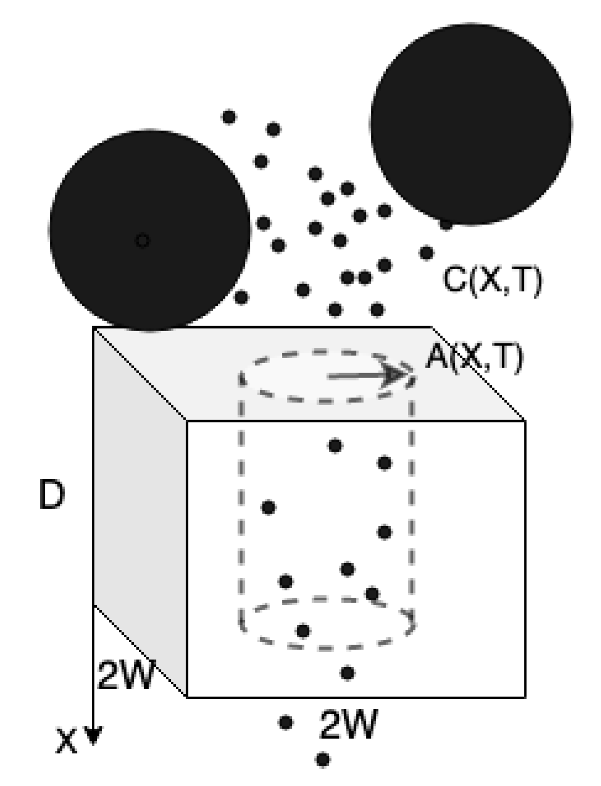
The initial investigations in this part will focus on the flow and small particles diffusion within a single pore of a membrane. The basic set-up is schematized in Figure 2 (described in detail below): we assume that pores are slender tubes spanning the membrane of length D, with variable radius , arranged in a -periodic square lattice. Initially, all pores have specified radius, . As mentioned earlier, we assume an axisymmetric pore, with axis of symmetry in the X-direction perpendicular to the plane of the membrane. We consider that the membrane is made up of a periodic array of such identical channels (if channels are not identical, one can replicate the results in the -plane for the rest of channels), and we seek solutions for the flow and particle concentration within a single channel, in the cylindrical coordinates in which properties vary only in X, R and time T (note that the cross-sectionally averaged variation only happens in X and time T). The small particles are transported down the pore in positive X-direction and may be deposited on the pore wall during the filtration process.
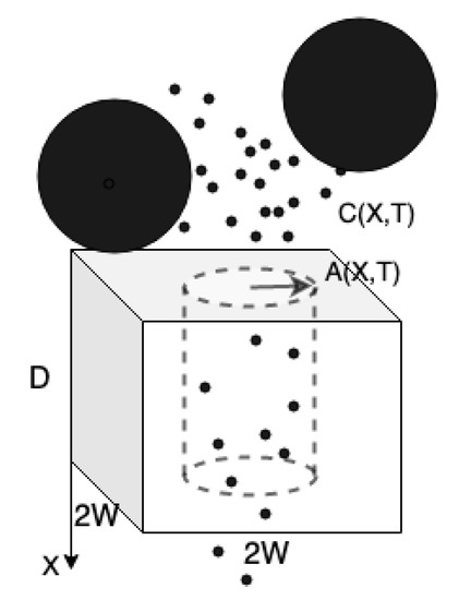
Figure 2.
This is a schematic, showing the single unit of a membrane, which is assumed repeated in a square lattice. Two species of particles are indicated here: (i) small particles and (ii) large particles. Small particles, at concentration , enter the pore and deposit within. Large particles block the pore inlet.
2.1.1. Darcy Flow Model of Filtration
Our model considers the flow is generated by a constant pressure drop across the membrane. Therefore, the superficial Darcy velocity, which is the imaginary flow velocity through the unit cell with the cross-section for a single pore, , satisfies the following equation
where is the membrane permeability at depth X and time T. The boundary conditions at the upstream and downstream membrane surfaces are given by constant pressure drop as follows
The pore velocity , and superficial Darcy velocity U are related by
where is the axisymmetric pore radius, which will change in depth and time during filtration process. This equation is obtained by a simple flux balance argument [18,21,27,28,29].
2.1.2. Blocking by Big Particles
As we mentioned in Section 1, we consider two fouling mechanisms during filtration process: big particles block the pores inlet and small particles deposit on pore walls. In this section, we will introduce a model describing the pore blocking by big particles [21,29]. Please note that initially, all pores have specified radius, , and are unblocked. The flux through each individual pore, satisfies
where is the pore resistance per unit of the membrane depth. The flux through a blocked pore, , is then given by
where represents the resistance per unit length of the blocked pore and the dimensionless parameter characterizes the additional resistance caused by a large particle, which sits over the pore inlet. This parameter reaches a high value when the pore is completely blocked by large particles and only a small part of the flow can go through it. The number densities of unblocked pore per unit area is denoted by , hence the number densities of blocked pores per unit area is , given . Therefore, the superficial Darcy velocity can be expressed in terms of , since the flux of the fluid through the membrane per unit area is
After substituting for and from (4) and (5) respectively, we obtain a modified equation for Darcy velocity (considering both blocked and unblocked pores simultaneously):
Please note that is used to obtain (7). Then, the next step is to study the evolution of to complete the blocking model. The assumption here is that the pore will only be blocked at the inlet. When a particle which is larger than the initial pore inlet arrives, causing a blockage and therefore additional resistance will be added to the system. Please note that the large particles will not interact with each other. We define as the cumulative large-particle-size distribution function. Therefore, the concentration of particles with radius is , where . Then, the number density of unblocked per unit area, evolves according to
More detailed derivation of this equation and further analysis of is implemented in [21,29].
2.2. Small Particle Deposition
Here we present a model for small particle concentration within a pore. Using careful asymptotic analysis (which will be provided in detail later in Section 3.1 and Section 3.2), the dimensional cross-sectionally averaged concentration of small particles , is given by
where is the diffusion coefficient of small particles and is the particle-wall attraction coefficient, describing particles deposition on the pores wall. Needless to say, at the beginning of the filtration process, particles are absorbed to the pores wall but after the first layer particles deposition occurs, they stick on top of each other. In other words, initially represent the particle-wall attraction coefficient and later, captures the physics of particle-particle attraction. Therefore, should be a function of space and time as well as the properties of the membrane and particles. In this paper, we assume is constant throughout a filtration process, but our model readily can be extended to the general scenario. From now on, we call the stickiness coefficient to represent the attraction of particle-wall as well as particle-particle. Equation (9) is subjected to the inlet and outlet boundary conditions [26,30,31]
Please note that in the limit , (9) reduces to
denoting that the particle diffusion is neglected, when Péclet number (defined as , where and will be discussed in detail later) is large [18,21,27,28,29]. On the other hand, for small Péclet numbers the effect of particle diffusion should be considered to be shown in (9). As a consequence of particle deposition on the pores wall, the pore radius shrinks. Therefore, we propose that the rate of change for the pore radius is proportional to the particle concentration at a particular depth
where is a constant related to particle size. This equation simply assumes that the pore cross-sectional volume per unit depth shrinks at a rate given by the total volume of particles deposited locally [18,21,27,28,29]. As mentioned earlier, the initial pore radius is prescribed
3. Scaling and Nondimensionalization
Please note that we chose to nondimensionalize time on the blocking time scale (see (8)). With the scaling above, we have the following dimensionless models for , , , , , with the meaning of Darcy velocity, cross-sectionally averaged pore velocity, pressure, pore radius, the number density of unblocked pores and cross-sectionally averaged particle concentration, respectively. Therefore, we have
with boundary and initial conditions
In the following subsections, we will explain how to obtain the dimensionless advection-diffusion model (18) from the full advection-diffusion equation based on the order of Péclet number.
3.1. Fluid Dynamics and Particle Concentration Equation
Please note that stars on the dependent variables here indicate the additional R-dependency, while the unstarred dependent variables are averaged over the pore cross-section. There are two time scales introduced in our model: the first one is related to the filtration flow velocity and the second one is originated from the rate of change in pore radius due to particles deposition. Since the time scale of membrane morphology change due to particle deposition is much longer compared to that of flow velocity, we employ a quasi-static model, where the domain of the flow is and . The pore velocity vector and the pressure satisfy the Stokes equations with inertia being neglected in all scenarios considered here (the Reynolds number is small in many filtration scenarios [21,22,23,26,27,29], especially in the ones where particle diffusion is essential)
where is the fluid viscosity. The Stokes equations are subjected to no penetration and no slip boundary conditions
where and are the unit normal and tangent vectors respectively, to the pore wall. We consider constant pressure driven flow, therefore the boundary conditions for the pressure are
The basic set-up considered is schematized in Figure 2 earlier. The modeling challenge is how to link the pore velocity to measurable particle concentration characteristics to obtain a predictive model. During the deposition process, the particles are carried by the flow and deposited on the pore wall due to the attraction between the pore walls and particle molecules. The attraction factor depends on the membrane and particles properties, and may vary from one membrane to another.
We consider the effects of small particles diffusion in the deposition model by studying the full advection-diffusion equation for the small particle concentration. Assuming a typical pore radius is much smaller than the membrane depth, , the dominant contribution of the diffusion term in our advection-diffusion model will be both the radial and axial diffusion in a distinguished limit of Péclet number. The full advection-diffusion equation for the small particle concentration that we must consider is
where is the flux of particles and is the diffusion coefficient of small particles. The boundary conditions are [21,26,30,31]:
where and are the particle concentration and stickiness coefficient respectively, as introduced previously. The second boundary condition in (25) simply says that the particle concentration does not change at the pore outlet, and the last condition is a general particle deposition law at the pore wall [26]. Since the model is assumed to be quasi-static, we have the steady-state form of the advection-diffusion Equation (24),
Please note that in obtaining (26) from (24), we use the continuity equation, . Moreover, with the assumption that , the wall deposition boundary condition becomes
To gain further insight into the dynamics of flow through the membrane, we define the averaged pore velocity , and particle concentration C, as
3.2. Derivation of the Dimensionless Diffusion Model
Please note that in order to derive the full advection-diffusion equation for small particle concentration, we need to conduct asymptotic analysis, based on the assumption (pores have small aspect ratio, i.e., their typical radius is smaller than their length), for the dimensionless Stokes and advection-diffusion equations by adopting the following scaling:
The dimensionless pressure boundary conditions in (23), after scaling, become
We now introduce expansion of dependent variables in powers of :
From (30) and (34), we obtain that the pressure is independent of the radial coordinate r at the leading order, i.e., . The dimensional boundary condition (22) can be simplified (by using the approximation )
since and . Solving for the leading order pore velocity ((31) and (32) using (35)) and boundary conditions ((33) and (35)) yield the leading orders pore velocity and pressure respectively,
So far, we have solved the Stokes equations in a single pore. Using the same velocity scaling for (28) as in (29), the dimensionless cross-sectionally averaged pore fluid velocity becomes, to leading order,
We now continue to find a simplified solution to the advection-diffusion equation. We non-dimensionalize (25)–(27) using the same scaling as in (29),
subject to the dimensionless boundary conditions
where is the small particles Péclet number. Since Péclet number is defined as the ratio of advective to diffusive transport rates, it can be considered to be a criterion measuring the importance of diffusion. Here we consider a distinguished limit of small particles Péclet number, , where we need to consider effects of axial diffusion in the filtration process. With this, the expansion (34) and conducting asymptotic analysis for (38) at and , we find out that particle concentration; and therefore their cross-sectionally averaged forms, at these orders are independent of r, i.e.,
At , Equation (38) reduces to
Applying the cross-sectionally averaged operator to (41) gives
Similarly, we can convert the third dimensionless boundary condition in Equation (39) into
4. Results
We present and illustrate some simulations of the model (15)–(20) introduced in Section 3. We first demonstrate how the membrane pore velocity, small particle concentration and pore radius evolve during filtration process; then we show how filtration outcomes change by varying Péclet number and the stickiness coefficient ; and finally we will find the optimum pore profile for a chosen performance measure.
Our model contains the following dimensionless parameters: , which describes the pore radius shrinkage rate; , characterizes the additional resistance formed when a large particle sits over a pore; , which is the dimensionless stickiness coefficient, capturing the physics of attraction between particles and the pore wall; and Pe, represents the degree of diffusion effects in filtration. While conducting the simulations, we follow the same assumptions on values of dimensionless parameters proposed in [21]. Therefore, we fix the additional resistance and distribution of large particle sizes in (17), which means all of the large particles are larger than the pores inlet and cannot enter in. Originally, we set and , but later we will change the values of and to gain insight into filtration performance stemming from either the change of membrane or properties of particles. Since and are correlated by the dimensional stickiness coefficient , whenever varies (due to change in membrane and particles properties or ), we need to keep (see (18) and (19)). In reality, the values of these parameters vary in different applications and depend on the properties of the feed solution; however, we believe that our models can give reliable predictions when detailed data from industries are provided. We consider a uniform initial pore profile where the initial pore radius is characterized by . Although we run simulations for uniform pore profiles, our model can be applied to any axisymmetric pore. Please note that in this paper, we assume the filtration occurs in the slow flow rate regime, where the particles diffusion plays a main role in the filtration process.
We conduct our numerical simulations to solve the model until the pore shrinks to zero (), which means that the membrane is no longer permeable and the flux through it drops to zero at the stopping time . The numerical scheme employed is center in space, backward in time, with second-order accurate finite difference spatial discretization of the equations, and an implicit time step in the pore-blocking Equation (19). Simulations for the model (15)–(20) summarized in Section 3 have been performed and we present results for the model regarding the scenarios when diffusion effect is taken into account as discussed in the previous section.
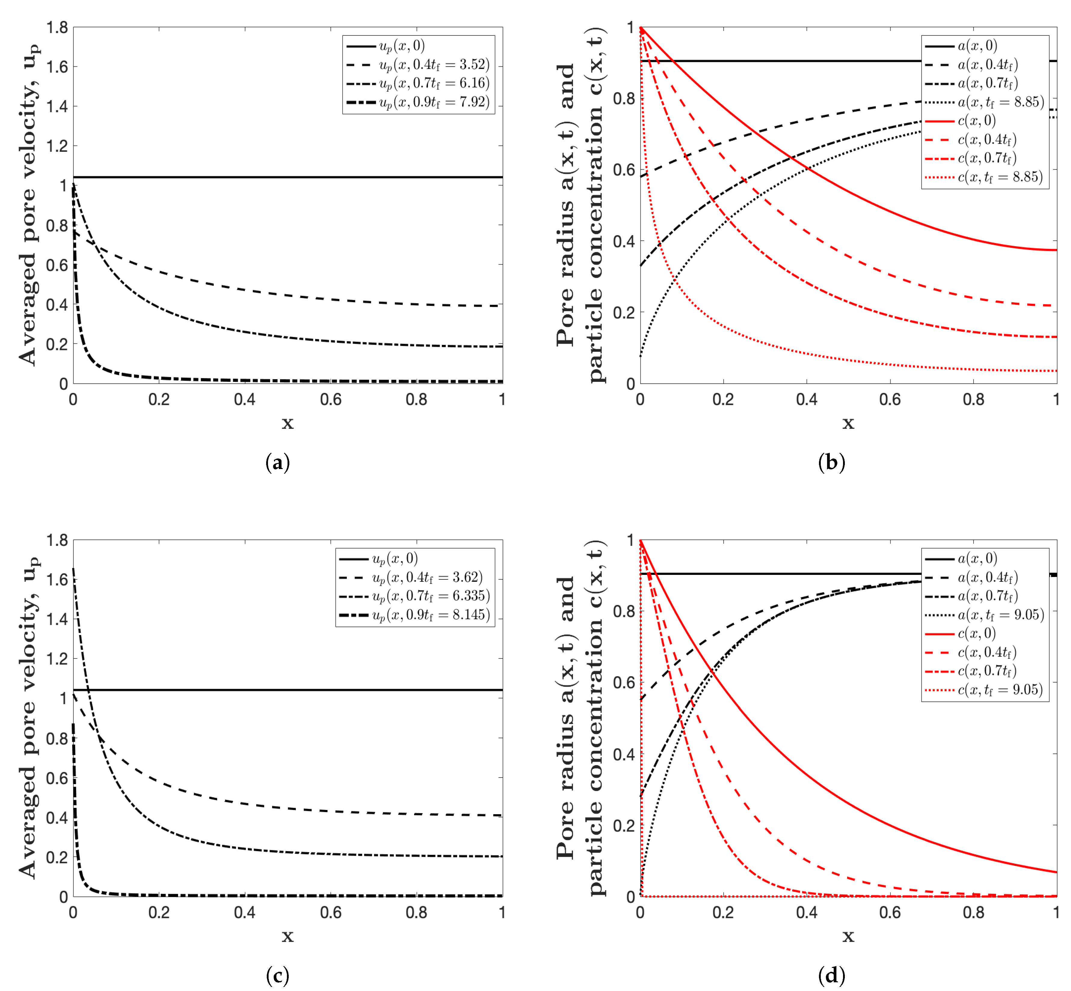
The main results are shown in Figure 3: we simulate the model for the uniform initial profiles , with parameters , and . The Péclet number is chosen to be 2, which describes the ratio of advective to diffusive transport rates. Please note that when , we only consider the effect of particle advection. Figure 3a,c show the cross-sectionally averaged pore velocity (when and respectively), while Figure 3b,d show the pore radius and the concentration of small particles at various times up to the final blocking time (when and respectively). A notable striking feature of these plots is that the pore shrinks at a higher rate at the pore inlet than outlet, and the pore closure occurs first at the upstream membrane surface. This is consistent with the plot regarding the pore velocity shown in Figure 3a,c. At the beginning of the filtration process, the pore velocity is constant for the uniform channel, but it promptly changes into a non-uniform one, with different pore velocity along the pore depth, representing the effect of continuity (see (15)). The main feature of Figure 3d, where only particle advection is considered (), is that the shrinkage mainly occurs at the pore inlet, more than what shown in Figure 3b, demonstrating a significant change due to diffusion effects in the filtration process. The other consequence of diffusion effects is that more particles escape during the filtration process (see Figure 3b), thus the particle concentration at the pore outlet increases a lot compared to the results shown in Figure 3d, where diffusion has no role there. Furthermore, comparing these two plots describing the shrinkage of pore radius brings us to this conclusion that by considering diffusion effects, the pore shrinks more in a uniform way along the axial direction, noticing that the pore outlet shrinks remarkably compared with that of advection simulation. These changes are also correlated with the model (19) assuming that the speed of radius shrinkage is proportional to particle concentration at depth x, meaning that for larger amount of particle concentration, the pore radius shrinks more.
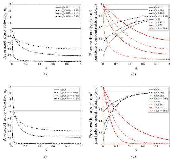
Figure 3.
(a) The cross-sectionally averaged pore velocity with . (b) the pore radius and particle concentration at several different times up to the final blocking time (, indicated in the legends) with . (c,d) are as (a,b) respectively, with . All four simulations are for a uniform initial pore profile , with , and .
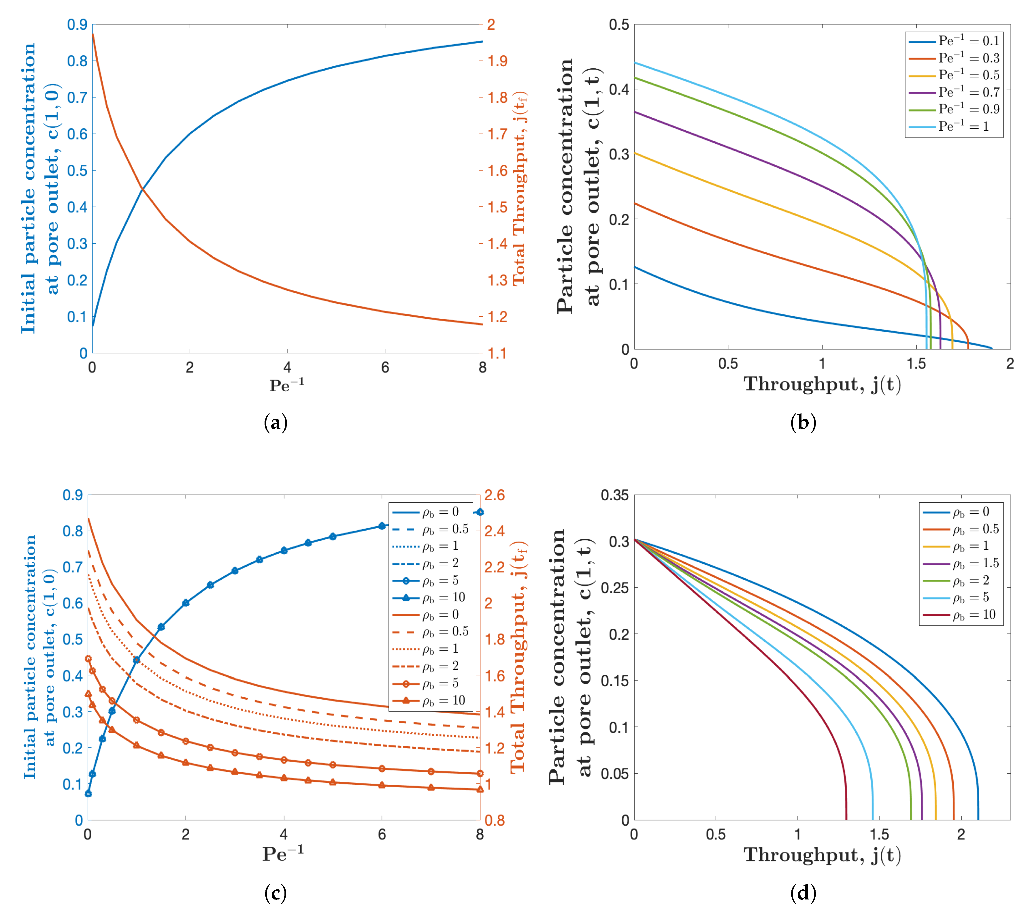
Considering the effects of particles diffusion, we would study how variation of the axial diffusion influences the filtration performance. We consider the particle concentration at the pore outlet and total throughput (definition is given below) as indices to reflect the filtration performance. The blue curve in Figure 4a presents how the inverse of Péclet number , affects the initial particle concentration at the pore outlet . For a clearer illustration of the graph tendency, we choose ranging from 0 to 8. This curve demonstrates that the initial particle concentration at the pore outlet increases significantly with . This mainly stems from the fact that the inverse of Péclet number represents the strength of particles axial diffusion, saying that more particles would diffuse out of the pore for larger values of . In particular, when , the corresponding particle concentration at pore outlet is 0.07, describing the case that only particle advection is being considered. This number is consistent with the results shown in Figure 3d. The red curve in Figure 4a describes how total volume of filtrate processed (so-called total throughput) varies with the inverse of Péclet number. Please note that the flux is directly proportional to the averaged Darcy velocity, therefore we define our dimensionless flux by ; throughput is then defined by . The results here show that the total throughput , decreases as increases.
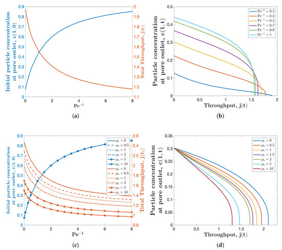
Figure 4.
(a) Initial particle concentration at the membrane downstream and throughput versus the inverse of Péclet number . (b) Particle concentration at the membrane downstream versus throughput for several different values of . Both simulations are for the uniform initial pore radius profile , with , and . (c,d) are similar to (a,b) respectively, for several different values of , while in (c).
Figure 4b shows the relationship between the particle concentration at the membrane downstream (pore outlet) and the total throughput . Each curve in the figure corresponds to a different value of the inverse of Péclet number , shown in the legend. The intersection of each curve and the y-axis represents the initial particle concentration at the pore outlet. As the filtration process proceeds, the throughput increases and the particle concentration at the pore outlet decreases to zero gradually. Comparing these curves in Figure 4b illustrates that the particle concentration increases as the Péclet number decreases. Meanwhile, as we increase , the total throughput decreases, shown as a smaller intercept with the x-axis. These observations are consistent with the ones shown in Figure 4a. In addition, Figure 4c,d are similar to Figure 4a,c respectively, for several different values of , which characterizes the additional resistance formed when a large particle sits over a pore. Please note that in Figure 4c, is used. The curves with in these two figures, represent the filtration scenario with no large particles included. These curves in Figure 4c,d, collectively show that the initial particle concentration at the pore outlet , does not change with , while the particle concentration at the pore outlet at latter times (, ) and the total throughput both decrease as increases. The effects of large particles on the filtration performance were studied in detail in [21].
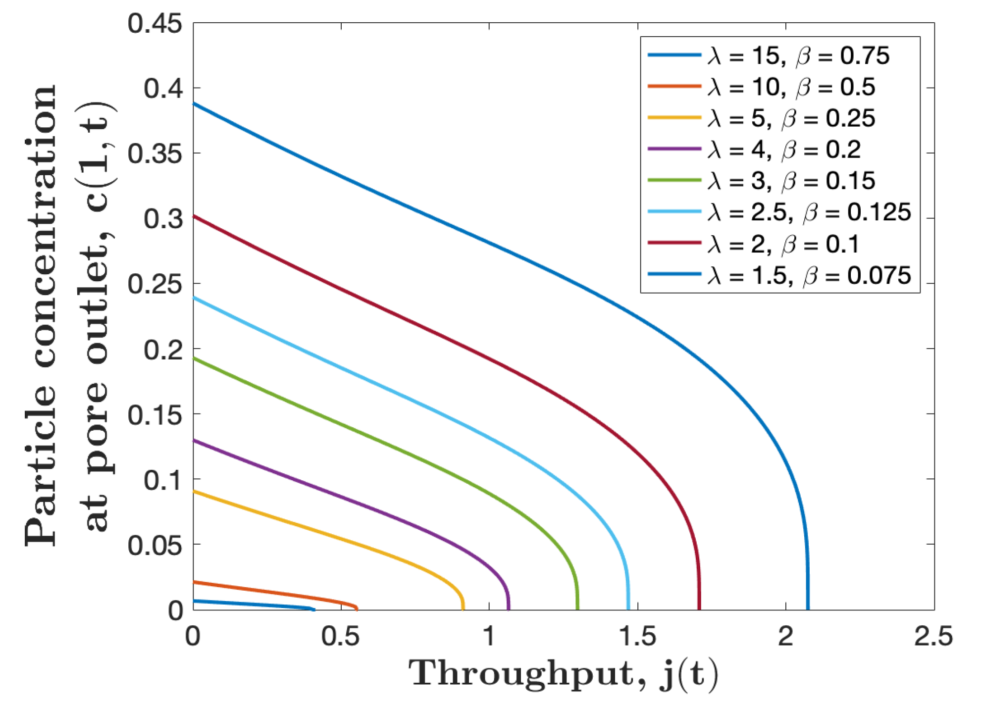
As demonstrated above, particles concentration at the pore outlet increases with the axial particle diffusion. Therefore, we may need to improve membrane properties whenever the filtration application requires less particles concentration at the membrane outlet. To do so, we study the influence of stickiness coefficient to reduce particles concentration in the filtrate. The two dimensionless parameters involved in our model and depend on , therefore they are not independent and should be varied proportionally at the same time if varies, i.e., . The change in the stickiness coefficient presents the variation of the membrane material or the particle properties in the feed solution. The small values of correspond to a weak membrane-particle and-particle-particle attraction, whereas the larger values represent strong attraction between membrane and particles in the feed solution. Figure 5 shows that membranes with larger values of give less particle concentration at the outlet with trade-off of having less total throughput. Hence, the type of membrane that should be employed in real applications depends on the purpose of the filtration. If more throughput is needed and relatively higher particles concentration is allowed, then a membrane with small should be used. On the other hand, if the purpose of the filtration is to separate particles from the feed solution as fine as possible, then a membrane with a larger value of should be adopted.
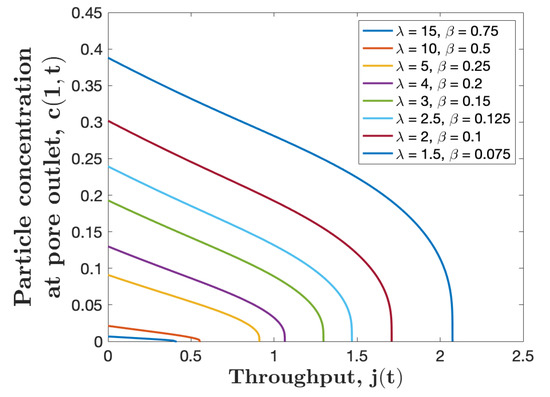
Figure 5.
Particle concentration at the membrane downstream , versus throughput for several values of with the initial pore profile , , and . We set (corresponding to varying ).
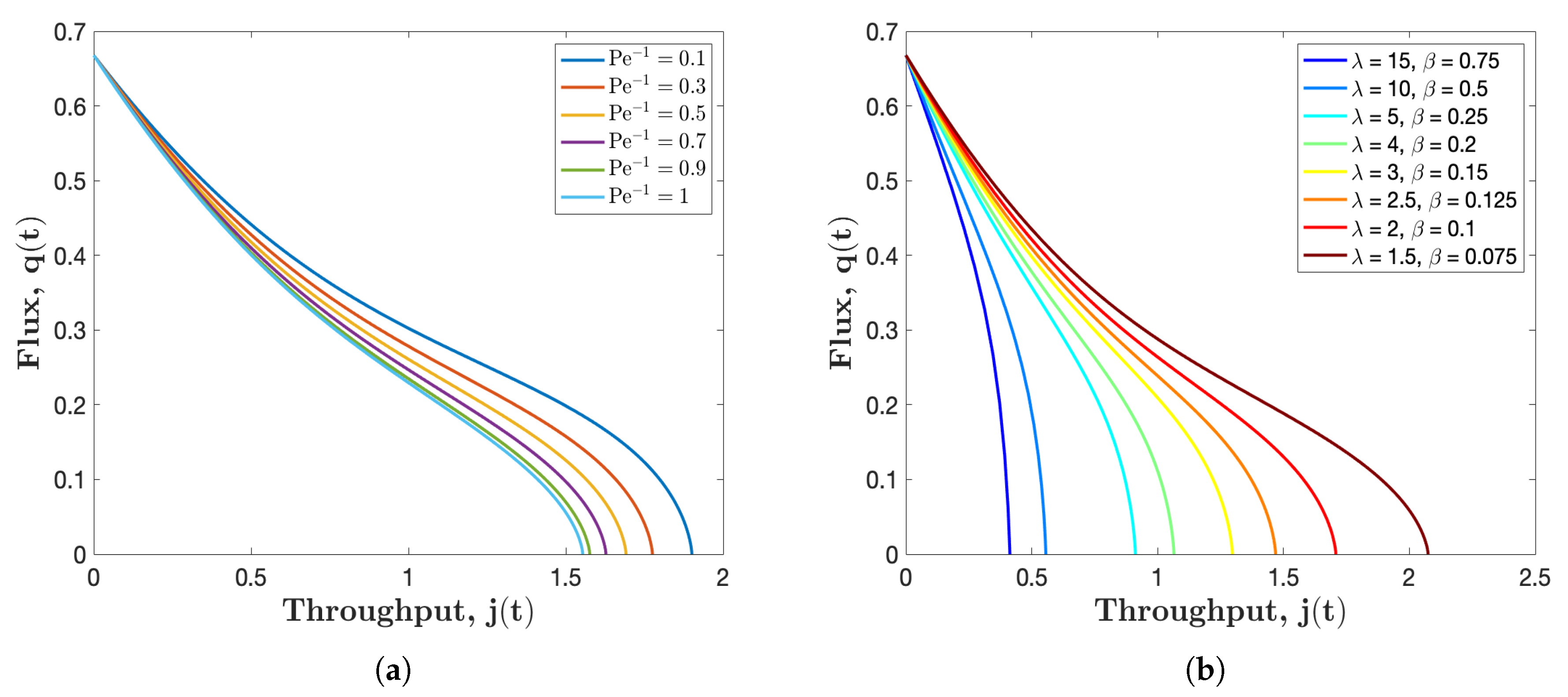
A prevailing characterization of filtration performance is the relationship between the flux and throughput through the membrane. Figure 6a illustrates the so-called flux-throughput graphs for several different values of the inverse of Péclet number . From these plots, we can observe that the total throughput decreases with Péclet number . This can be interpreted that for slow filtration process, less feed solution is processed. As shown, for a fixed total throughput, flux will be less for larger values of . This phenomenon is because that by definition, the flux is directly proportional to the averaged Darcy velocity, which is smaller for larger (consistent with the results of Figure 3). Moreover, each flux-throughput curve in Figure 6a is concave at the beginning and then becomes convex during the last stage of filtration. This change in curvature is consistent with results observed in the experimental systems [32] as well as the model simulations [21].
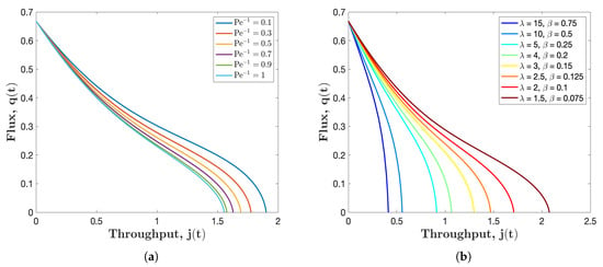
Figure 6.
Flux versus throughput graphs for several different values of: (a) , with and ; and (b) and , with and . In both figures the initial pore profile and .
We run similar simulations as shown in Figure 6b, where we fix the value of Péclet number and at 2, then observe how and affect filtration performance. The conclusion is that when the membrane stickiness is enhanced ( and increase proportionally), less feed solution is processed. This can be explained by that when more particles are deposited on the pores wall due to increment of stickiness coefficient, the pore shrinks faster leading to a smaller volume of throughput. It is worth noting that when the stickiness is very large (e.g.,: the curve with ), the flux drops dramatically during filtration process. In this case, the filtrate processed is less than a fourth of that of the membrane with . Recalling from Figure 5, we obtain the conclusion that membrane with higher yields a better filtration performance as less particles will escape from the membrane. However, from Figure 6b, we come to another conclusion that membrane with low is preferred when our interest is to achieve more filtrate. Therefore, the selection of membrane depends vastly on the goal and the requirement of the target filtration, which may vary in different filtration scenarios.
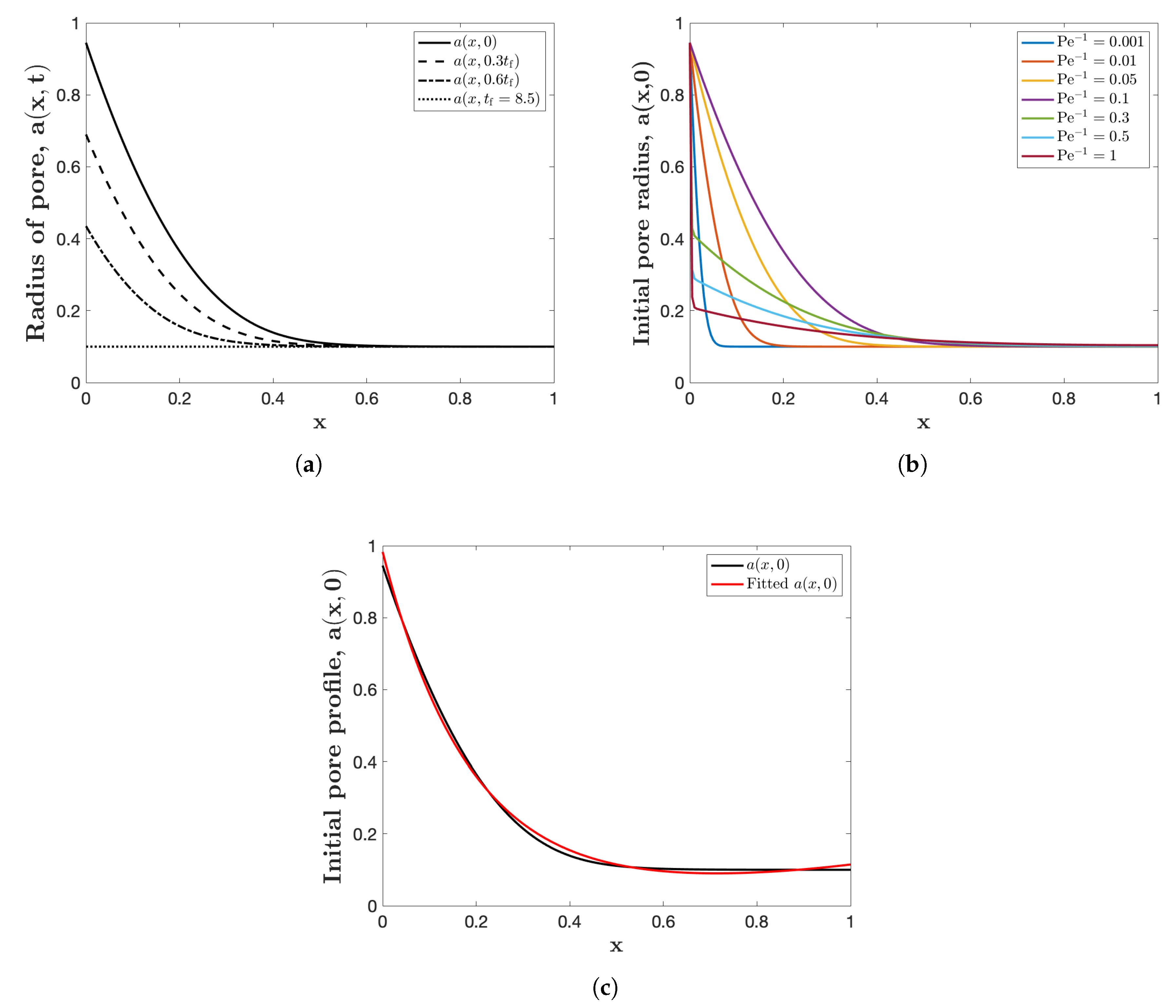
A question of interest to manufacturers is: What is the optimum permeability profile as a function of depth through the membrane? For our model, this question translates to: What is the optimal shape of the filter pores? To answer this, we must first choose a measure of filtration performance [18,21,22,23,29]. The most appropriate measure will vary depending on the user requirements, but for purposes of illustration, we study which initial membrane pore profile maximizes the cumulative removal of contaminants from the solvent, as well as the total throughput. As shown in Figure 3b, the membrane pore closure mainly occurs at the upstream side, while the rest of pore remains untouched. This means that in real application, we must discard and replace the membrane, even if a large proportion of the membrane remains unused. Hence, it is efficient to have a membrane structure resulting in a uniform final porosity or pore profile, meaning that the most part of the filter is being used to remove particles. To design such a membrane with this initial pore profile, the model (19) is reversed in time. Please note that the full advection-diffusion equation is a parabolic equation, therefore it is not reversible in time, but due to quasi-static assumption for this equation (see (26)), we will not encounter this issue [22]. Starting with a uniform pore profile and run the simulation backwards in time, we attain an initial pore profile which enables the filtration process to end with a uniform pore profile. Please note that to bypass the problems brought by the numerical simulation, we define a uniformly closed pore to have radius of 0.1.
Figure 7a demonstrates the evolution of pore radius for reversing time simulation with . The solid curve demonstrates the initial profile for the pore, which closes uniformly, and as expected, the profile requires a broader radius at the pore inlet, which matches the pore shrinkage pattern shown in Figure 3b. To investigate how the Péclet number impacts the initial pore profile, Figure 7b is presented. As shown, there is no clear pattern on how the initial pore profile changes as varies, but the common point in all curves is that the pore inlet should be initially wider than the pore downstream. Finally, the black curve in Figure 7c represents the initial pore profile which leads to a uniform closure at the final time. The red curve is the exponential fit
within confidence bounds, when .
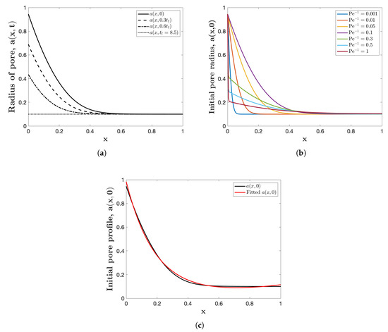
Figure 7.
Reverse time filtration simulations: (a) pore radius at several different times with . (b) Initial pore radius for several different . (c) The initial pore profile and the fitted exponential curve when . All figures are simulated with , , , and .
5. Conclusions
In this paper, we have presented a mathematical model describing filtration performance including the separation efficiency and change of membrane morphology. In particular, the key result is an advection-diffusion equation demonstrating the change of small particle concentration in the Darcy driven flow through the membrane filter. The model focuses on the diffusion effect of small particles in the feed solution, while blocking at the pore inlet due to large particles is also included. Although our model gives a promising prediction for the filtration process, it contains several dimensionless parameters which are unknown and can vary a lot in different applications. For example, we lack empirical data to determine exact values of the following parameters, : additional pore resistance when it is blocked by large particles; : the stickiness coefficient and : the dimensionless pore shrinkage rate or the adsorption rate coefficient. While the presented simulations use some tenable inputs for these parameters [21], we believe that our model can give precise predictions when accurate data is provided for a specific application. Although our model studies the simplest membrane pore profile, which is initially uniform (), it can be applied to any axisymmetric pore profiles characterized by a depth-dependent initial radius . In terms of operating mechanisms, our model is simulated under prescribed pressure drop but can be readily extended to a constant flux driven flow.
In the simulations based on our assumptions and chosen parameters, the effects of particle diffusion on the particle concentration as well as the pore radius shrinkage are studied, as shown in Figure 3b. This figure, which describes how the particle concentration in the feed solution and pore morphology evolve, indicates that particle concentration increases in a more uniform way compared to the case that the diffusion is neglected and only particle advection is considered (see Figure 3d). The striking feature is that pore shrinks with a higher rate at the pore inlet, consistent with Figure 3a, where the cross-sectionally averaged pore velocity is higher at the inlet. Thus, to better understand the effects of diffusion on the filtration results, we look into the change of particle concentration and total throughput with different values of the inverse of Péclet number . The results of Figure 4a show that the initial particle concentration at the membrane pore outlet increases whereas the total throughput decreases when a stronger diffusion effect is considered (recall that a larger value of corresponds to a more strong diffusion scenario). Figure 4b further studies the relationship between the throughput and particle concentration at the pore outlet for several different values of .
From both Figure 4a,b, since the particle concentration at the pore outlet is relatively high compared to the case that only the advection of particles is considered (), membrane properties need to be improved to achieve a superior separation efficiency. We alter two dimensionless parameters: the stickiness coefficient ( ) and the pore shrinkage rate ()), to represent the change of membrane properties. Since and are correlated by the dimensional stickiness coefficient , we keep the relation of while adjusting their values. Please note that the large values of corresponds to strong membrane-particle or particle-particle attraction; hence intuitively this should be employed in filtration application. However, Figure 5 confirms that increasing of results in a low throughput, which is also not desirable. Therefore, the trade-off between a smaller particle concentration or a larger throughput needs to be balanced. As for whether the particle concentration should be the priority or the total throughput should be optimized first, different filtration applications have distinct requirements and cannot be concluded arbitrarily.
Another popular characterization of filtration process is the flux-throughput plot. A new information provided by Figure 6a is that while the throughput is fixed, the flux is less for a larger inverse of Péclet number. Similarly, Figure 6b indicates that the flux with higher is smaller at a certain value of throughput. Moreover, the curvature of Figure 6a is consistent with the experimental data [32] as well as the model simulations [21]. Meanwhile, we notice that the filtration process is terminated when the radius closure occurs at the pore inlet, even with most part of the pore still unused. Hence, we run the simulation backwards in time to obtain a pore profile which can results in a uniform closure. The corresponding initial pore profile is presented in Figure 7, which leads to the most efficient use of the membrane.
Although our simple model has a lot of potential and presents many promising results, there are still lots of aspects to be improved. There is one fouling regime lacking in our model: the process of cake formation, which happens when membrane pores are blocked and small particles deposit on, adding extra resistance to the filtrate [29]. In our simulation, the filtration for a single pore is terminated when its radius shrinks to zero. However, in reality the fouling mechanism can be more complicated, and the duration of filtration process may be longer than what shown here. On the other hand, since the separation efficiency towards the end of filtration process is very poor, our approach is to neglect the effect of cake formation, which is a valid assumption. Another drawback is that as we mentioned above, our model is limited to axisymmetric pore profiles. However, in real applications, as shown in Figure 1, the pore profile can be really complexly structured. This will be a promising field to continue our study [28,33,34]. We may also deepen our study by considering the stochastic behavior of small particles during filtration process. When the flow rate is low, small particles in filtrate may not only diffuse around but also follow stochastic process, which can also be an important driving force for small particle deposition on the membrane pores wall.
Author Contributions
P.S. designed the study and derived the mathematical model. S.Y.L., Z.C. and P.S. wrote the paper and performed numerical simulations. All authors have read and agreed to the published version of the manuscript.
Funding
Shi Yue Liu and Zhengyi Chen acknowledge financial support by the Summer Undergraduate Research Experience (SURE) offered by the Courant Institute of Mathematical Sciences, New York University. P.S. gratefully acknowledges financial supports in part by the National Science Foundation (NSF) Research Training Group in Modeling and Simulation Grant No. RTG DMS-1646339, a travel award, and an Institutional Support of Research and Creativity (ISRC) grant provided by New York Institute of Technology.
Conflicts of Interest
The authors declare that they have no conflict of interest.
References
- Iritani, E. A review on modeling of pore-blocking behaviors of membranes during pressurized membrane filtration. Dry. Technol. 2013, 31, 146–162. [Google Scholar] [CrossRef]
- O’Melia, C.R. Particles, pretreatment, and performance in water filtration. J. Environ. Eng. 1985, 111, 874–890. [Google Scholar] [CrossRef]
- Ling, B.; Battiato, I. Rough or wiggly? Membrane topology and morphology for fouling control. arXiv 2018, arXiv:1809.00217. [Google Scholar] [CrossRef]
- Roy, S. Innovative use of membrane technology in mitigation of GHG emission and energy generation. Procedia Environ. Sci. 2016, 35, 474–482. [Google Scholar] [CrossRef]
- Bhattacharjee, C.; Saxena, V.; Dutta, S. Fruit juice processing using membrane technology: A review. Innov. Food Sci. Emerg. Technol. 2017, 43, 136–153. [Google Scholar] [CrossRef]
- Munirasu, S.; Haija, M.A.; Banat, F. Use of membrane technology for oil field and refinery produced water treatment?A review. Process. Saf. Environ. Prot. 2016, 100, 183–202. [Google Scholar] [CrossRef]
- Monte, J.; Sá, M.; Parreira, C.; Galante, J.; Serra, A.R.; Galinha, C.F.; Costa, L.; Pereira, V.J.; Brazinha, C.; Crespo, J.G. Recycling of Dunaliella salina cultivation medium by integrated membrane filtration and advanced oxidation. Algal Res. 2019, 39, 101460. [Google Scholar] [CrossRef]
- Apel, P. Track etching technique in membrane technology. Radiat. Meas. 2001, 34, 559–566. [Google Scholar] [CrossRef]
- Mohammed, K.; Sahu, O. Recovery of chromium from tannery industry waste water by membrane separation technology: Health and engineering aspects. Sci. Afr. 2019, 4, e00096. [Google Scholar] [CrossRef]
- Ulbricht, M.; Schuster, O.; Ansorge, W.; Ruetering, M.; Steiger, P. Influence of the strongly anisotropic cross-section morphology of a novel polyethersulfone microfiltration membrane on filtration performance. Sep. Purif. Technol. 2007, 57, 63–73. [Google Scholar] [CrossRef]
- Drioli, E.; Giorno, L. Membrane Operations: Innovative Separations and Transformations; John Wiley & Sons: Hoboken, NJ, USA, 2009. [Google Scholar]
- Ho, C.C.; Zydney, A.L. A combined pore blockage and cake filtration model for protein fouling during microfiltration. J. Colloid Interface Sci. 2000, 232, 389–399. [Google Scholar] [CrossRef] [PubMed]
- Chellam, S.; Xu, W. Blocking laws analysis of dead-end constant flux microfiltration of compressible cakes. J. Colloid Interface Sci. 2006, 301, 248–257. [Google Scholar] [CrossRef] [PubMed]
- Bolton, G.R.; Boesch, A.W.; Lazzara, M.J. The effects of flow rate on membrane capacity: Development and application of adsorptive membrane fouling models. J. Membr. Sci. 2006, 279, 625–634. [Google Scholar] [CrossRef]
- Osada, Y.; Nakagawa, T. Membrane Science and Technology; CRC Press: Boca Raton, FL, USA, 1992. [Google Scholar]
- Sauret, A.; Somszor, K.; Villermaux, E.; Dressaire, E. Growth of clogs in parallel microchannels. Phys. Rev. Fluids 2018, 3, 104301. [Google Scholar] [CrossRef]
- Sanaei, P.; Richardson, G.; Tom, W.; Cummings, L. Flow and fouling in a pleated membrane filter. J. Fluid Mech. 2016, 795, 36–59. [Google Scholar] [CrossRef]
- Sun, Y.; Sanaei, P.; Kondic, L.; Cummings, L.J. Modeling and design optimization for pleated membrane filters. Phys. Rev. Fluids 2020, 5, 044306. [Google Scholar] [CrossRef]
- Grenier, A.; Meireles, M.; Aimar, P.; Carvin, P. Analysing flux decline in dead-end filtration. Chem. Eng. Res. Des. 2008, 86, 1281–1293. [Google Scholar] [CrossRef]
- Goldrick, S.; Joseph, A.; Mollet, M.; Turner, R.; Gruber, D.; Farid, S.S.; Titchener-Hooker, N.J. Predicting performance of constant flow depth filtration using constant pressure filtration data. J. Membr. Sci. 2017, 531, 138–147. [Google Scholar] [CrossRef]
- Sanaei, P.; Cummings, L.J. Flow and fouling in membrane filters: Effects of membrane morphology. J. Fluid Mech. 2017, 818, 744. [Google Scholar] [CrossRef]
- Dalwadi, M.P.; Bruna, M.; Griffiths, I.M. A multiscale method to calculate filter blockage. J. Fluid Mech. 2016, 809, 264–289. [Google Scholar] [CrossRef]
- Griffiths, I.; Kumar, A.; Stewart, P. Designing asymmetric multilayered membrane filters with improved performance. J. Membr. Sci. 2016, 511, 108–118. [Google Scholar] [CrossRef]
- Matthies, J.H.; Hopp-Hirschler, M.; Uebele, S.; Schiestel, T.; Osenberg, M.; Manke, I.; Nieken, U. Up-scaling transport in porous polymer membranes using asymptotic homogenization. Int. J. Numer. Methods Heat Fluid Flow 2019, 30, 266–289. [Google Scholar] [CrossRef]
- Chen, V.; Fane, A.; Madaeni, S.; Wenten, I. Particle deposition during membrane filtration of colloids: Transition between concentration polarization and cake formation. J. Membr. Sci. 1997, 125, 109–122. [Google Scholar] [CrossRef]
- Taylor, G.I. Dispersion of soluble matter in solvent flowing slowly through a tube. Proc. R. Soc. Lond. Ser. Math. Phys. Sci. 1953, 219, 186–203. [Google Scholar]
- Sanaei, P.; Cummings, L.J. Membrane filtration with complex branching pore morphology. Phys. Rev. Fluids 2018, 3, 094305. [Google Scholar] [CrossRef]
- Gu, B.; Renaud, D.; Sanaei, P.; Kondic, L.; Cummings, L. On the influence of pore connectivity on performance of membrane filters. J. Fluids Mech. 2020, in press. [Google Scholar]
- Sanaei, P.; Cummings, L.J. Membrane filtration with multiple fouling mechanisms. Phys. Rev. Fluids 2019, 4, 124301. [Google Scholar] [CrossRef]
- Chen, J.S.; Liu, C.W. Generalized analytical solution for advection-dispersion equation in finite spatial domain with arbitrary time-dependent inlet boundary condition. Hydrol. Earth Syst. Sci. 2011, 15, 2471. [Google Scholar] [CrossRef]
- Guerrero, J.P.; Pimentel, L.C.G.; Skaggs, T.H.; Van Genuchten, M.T. Analytical solution of the advection–diffusion transport equation using a change-of-variable and integral transform technique. Int. J. Heat Mass Transf. 2009, 52, 3297–3304. [Google Scholar] [CrossRef]
- Giglia, S.; Straeffer, G. Combined mechanism fouling model and method for optimization of series microfiltration performance. J. Membr. Sci. 2012, 417, 144–153. [Google Scholar] [CrossRef]
- Fong, D.; Cummings, L.; Chapman, S.; Sanaei, P. On the performance of multilayered membrane filters. J. Eng. Math. 2020, in press. [Google Scholar]
- Sanaei, P.; Cummings, L.; Waters, S.; Griffiths, I. Curvature-and fluid-stress-driven tissue growth in a tissue-engineering scaffold pore. Biomech. Model. Mechanobiol. 2019, 18, 589–605. [Google Scholar] [CrossRef] [PubMed]
© 2020 by the authors. Licensee MDPI, Basel, Switzerland. This article is an open access article distributed under the terms and conditions of the Creative Commons Attribution (CC BY) license (http://creativecommons.org/licenses/by/4.0/).


