Article

Decoding the Relationships between Body Shape, Tail Beat Frequency, and Stability for Swimming Fish

1
Department of Mathematics, University of Akron, Akron, OH 44325, USA
2
Department of Biology, Tufts University, Medford, MA 02155, USA
*
Author to whom correspondence should be addressed.
Fluids 2020, 5(4), 215; https://doi.org/10.3390/fluids5040215
Submission received: 28 September 2020 / Revised: 9 November 2020 / Accepted: 14 November 2020 / Published: 20 November 2020
(This article belongs to the Special Issue Hydrodynamics of Swimming)

Abstract

:
As fish swim through a fluid environment, they must actively use their fins in concert to stabilize their motion and have a robust form of locomotion. However, there is little knowledge of how these forces act on the fish body. In this study, we employ a 3D immersed boundary model to decode the relationship between roll, pitch, and yaw of the fish body and the driving forces acting on flexible fish bodies. Using bluegill sunfish as our representative geometry, we first examine the role of an actuating torque on the stability of the fish model, with a torque applied at the head of the unconstrained fish body. The resulting kinematics is a product of the passive elasticity, fluid forces, and driving torque. We then examine a constrained model to understand the role that fin geometry, body elasticity, and frequency play on the range of corrective forces acting on the fish. We find non-monotonic behavior with respect to frequency, suggesting that the effective flexibility of the fins play an important role in the swimming performance.

1. Introduction

Many species of fish live in very complex, turbulent environments, including wave swept coral reefs and rapidly flowing streams [1] and swim stably despite large environmental forces. Yet the swimming motion of most fish is itself probably unstable. Much like backing up a car with a trailer attached, the center of pressure from thrust from the caudal fin is located behind the center of mass, an unstable configuration [2]. Similarly, the dorsal and anal fins, located above and below the center of mass, produce large forces that are not the same [3,4], likely producing a destabilizing torque. Finally, for many fishes, the center of mass is located above the center of buoyancy [5], leading to a static roll instability. Thus, it seems likely that most fish must actively stabilize themselves during swimming [6]. They have exquisite control over their pectoral [7] and pelvic fins [8], along with the dorsal, anal, and caudal fins [9], all of which are probably used for stability as well as propulsion.
Certain body forms are thought to be more stable—or really, less unstable—than others [6]. As an extreme example, boxfishes, which have a rigid carapace, are passively self-stabilizing due to bony ridges on their carapaces [10]. For other fishes, the evidence is less clear. Species with streamlined body shapes are found more often in fast flowing turbulent streams [11], but is that because their body shape is more stable, reduces drag, both, or because of some other factor?
In general, assessing the degree of instability of an unstable system is difficult. For a stable system, the canonical method involves applying small perturbations and measuring the time it takes the system to return to its stable equilibrium [12]. These approximations usually involve linearizing a nonlinear system about the equilibrium. For an unstable system, any small perturbation will ultimately cause the system to diverge, possibly passing through qualitatively different states in which the linear approximation fails. For fishes, the challenge is also that stabilization is an active process. Some have argued that one could quantify relative stability by examining how much an animal’s body orientation fluctuates during movement, for example, [13]; animals that pitch up and down more during swimming, for example, might be less stable than those that pitch less. However, larger fluctuations in orientation do not necessarily imply lower stability. It might be that animals with larger fluctuations are exerting less active control over their orientation, and could in fact be more passively stable than those with smaller fluctuations.
Here, we use a computational model of a swimming fish to examine a different way to assess stability. We simulate a fish with a flexible body, based on the shape and mechanics of the bluegill sunfish Lepomis macrochirus. This is a fluid–structure interaction problem, a ubiquitous type of problem in biology that has been examined with a number of computational frameworks. One such method is the immersed boundary (IB) method, first developed by Charles Peskin in the 1970s to examine the cardiovascular fluid dynamics of the human heart. Since then, the IB method has been used for a number of fluid–structure interaction systems that are in low to intermediate Reynolds regime. This includes many different biological systems pertaining to animal locomotion in fluids, such as undulatory swimming [14,15,16], jellyfish swimming [17,18,19,20], crustacean swimming [21], and insect flight [22,23].
We first demonstrate that the fish body in our simulations is unstable. Then, we augment the simulation by applying constraint forces that force the swimmer to remain in an upright orientation. These constraint forces represent the net additional force that a freely swimming fish would have to produce to stay upright. Most likely, such forces would be produced primarily by the pectoral fins, which are not included in our simulation. The magnitude of the constraint forces thus represents the degree of instability of the fish model; larger constraint forces means that the model is less stable. We find that stability, as assessed with our new metric, varies depending on the effective flexibility [16] and body shape of the fish model.

2. Methods

2.1. Fluid–Structure Interaction

The IB framework describes the fluid–structure interaction system using an Eulerian description of the equations of fluid motion and a Lagrangian frame to describe a deformable immersed boundary or body [24,25,26]. Let X = ( X , Y , Z ) U represent the Lagrangian coordinate system of the immersed structure, where U is denoting the Lagrangian coordinate domain. Let x = ( x , y , z ) Ω denote physical Cartesian coordinates, with Ω denoting the physical region of the fluid–structure system. The physical position of the material point X at time t is denoted with the mapping χ ( X , t ) Ω , such that the physical region of the structure at time t is χ ( U , t ) Ω .
The immersed boundary formulation of the equations of motion is given by
ρ u ( x , t ) t + u ( x , t ) · u ( x , t ) = p ( x , t ) + μ 2 u ( x , t ) + f ( x , t )
· u ( x , t ) = 0
f ( x , t ) = U F ( X , t ) δ ( x χ ( X , t ) ) d X
U F ( X , t ) · V ( X ) d X = U P ( X , t ) : X V ( X ) d X + U G ( X , t ) · V ( X ) d X
χ ( X , t ) t = Ω u ( x , t ) δ ( x χ ( X , t ) ) d x
where μ is the dynamic viscosity of the fluid, ρ is fluid density, u ( x , t ) = ( u x , u y , u z ) is the Eulerian material velocity at x , p ( x , t ) is the Eulerian pressure field, and G ( X , t ) represents an external body force. F ( X , t ) and f ( x , t ) represent the Lagrangian and Eulerian force densities, respectively. F is defined with respect to the first Piola Kirchhoff stress tensor in Equation (4) using a unified weak formulation (following [27]), in which the resulting force term accounts for both internal body forces and transmission forces at the boundary U and V ( X ) is an arbitrary Lagrangian test function. The Dirac delta function δ ( x ) = δ ( x ) δ ( y ) δ ( z ) is the kernel of the integral transforms of Equations (3) and (5). Here, Equation (3) couples the Lagrangian force density to the local Eulerian force density, while Equation (5) enforces the no-slip boundary condition of the structure with respect to the local fluid velocity.
This study uses a hybrid finite difference/finite element version of the immersed boundary (IB/FE) to approximate Equations (1)–(5). The IB/FE method uses a finite difference formulation for the Eulerian equations and a finite element formulation for the Lagrangian structure. More details of the IB/FE method can be found in Griffith and Luo [27].

2.2. Body Construction

The body shape for the model was constructed in Solidworks (2019 version; Dassault Systèmes, Waltham, MA, USA) based on images of a bluegill sunfish (Lepomis macrochirus) taken from lateral and ventral view. The fins were constructed by tracing the outline of the body and fins (Figure 1A), extruding that shape to a 1 mm thickness, and then rounding the edges with a fillet with a 0.2 mm radius. To construct the body, we assumed that it had an elliptical cross section and set the width equal to the body width from the ventral image and the height equal to the body height from the lateral image. We then joined the ellipses with a smooth swept extrusion (Figure 1B) and merged the body and fins into a single solid object in an STL file. The STL file was then used to generate a finite element hex-mesh of the body using Bolt (2018, Csimsoft).

2.3. Material Model and Driving Torque

In this study, the kinematics of the fish model emerge from the interaction between the passive elastic material properties of the body, a driving torque, and the resulting local fluid dynamics. Additionally, a subset of the simulation has a body force that maintains the body on a fixed (horizontal) x y plane. The body’s material properties as described using the first Piola–Kirchhoff stress tensor of a Neo–Hookean material model,
P = η F + ( λ det ( J ) η ) F T
where F = χ X is the deformation gradient of the body, J is the Jacobian of F , η is the shear modulus, λ is the bulk modulus. The shear and bulk moduli are defined respectively as
η = E 2 ( 1 + ν )
and
λ = E ν ( 1 + ν ) ( 1 2 ν ) ,
where E is the Young’s modulus and ν is the Poisson ratio.
We also actuate the model at one vertical axis, as if it was being twisted back and forth on a stick, similar to experimental models [28] shown to give good approximations of many kinematic features of fish swimming movements. The fish body is driven with a torque applied about a vertical axis that goes through the anterior region of the fish model, just in front of the dorsal fin. The region where the torque is applied is a cylinder of radius r c and the applied force magnitude at time t, F m a g ( t ) , is defined with respect to the distance between the material coordinates and the axis of applied torque, r,
F m a g ( t ) = F m a x f sin ( 2 π f t ) r r c if r r c 0 if r > r c ,
where F m a x is the maximum applied force magnitude and f is the frequency. Note that F m a g ( t ) is normalized with respect to f so that the cycle-averaged | F m a g ( t ) | is constant with respect to actuation frequency. The applied torque, G ˜ F , is then defined with respect to the radial coordinates of the undeformed mesh,
G ˜ F ( X , t ) = F m a g ( t ) sin ( θ ) , F m a g ( t ) cos ( θ ) , 0 if   Y 0 F m a g ( t ) sin ( θ ) , F m a g ( t ) cos ( θ ) , 0 if   Y < 0
where θ = cos 1 ( X / r ) . The force is then mapped to the current configuration of the mesh using the deformation gradient tensor,
G F ( X , t ) = F G ˜ F .
By mapping the force from the undeformed configuration to the current configuration, the region of applied torque is consistent on the body regardless of the deformation and rotation of the body.
Additionally, a subset of the simulations constrains the fish body to its initial horizontal plane. To do this, a body force is applied to the column where torque is applied. The body force is a stiff tether spring force dependent on the difference between the current and initial z-coordinates,
G T ( X , t ) = κ ( χ T ( X , t ) χ ( X , t ) ) if r r c 0 if r > r c ,
where κ is a spring constant and
χ T ( X , t ) = ( χ x ( X , t ) , χ y ( X , t ) , χ z ( X , 0 ) ) ,
which allows us to constrain only the z-axis. For unconstrained swimming, κ is set to zero.
The two body forces are then summed up
G ( X , t ) = G F ( X , t ) + G T ( X , t )
and substituted into Equation (4) as an external force on the body. All reference parameters for this study are listed in Table 1.

2.4. Body Coordinate System

To identify the roll, pitch, and yaw angles and torques, we created a body coordinate system for the fish. We constructed an orthonormal basis for the fish body at time t, { r F ( t ) , r S ( t ) , r T ( t ) } , where r F , r S , and r T are unit vectors that respectively point towards the front, side, and top of the fish body, with the center of mass as the origin. We then construct a rotation matrix, R ,
R ( t ) = r F ( t ) , r S ( t ) , r T ( t ) , R = R ( t ) [ R ( 0 ) ] T .
From R , we calculate the associated yaw, pitch, and roll of the body using Euler angle formulas [29].
To assess stability, we constrained the model to swim in the x y plane, then computed the constraint torques in the fish’s reference frame. The forward ( X F ) axis for the fish is defined as the swimming direction averaged over a tail beat. Since the fish is constrained to an upright orientation, the up axis ( Z F ) is the same as the global Z axis, and therefore the lateral axis Y F = Z × X F . The torque vector τ ( t ) is defined about the fish’s center of mass X C O M by
τ ( t ) = U ( X X C O M ) × G T ( X , t ) d X .
We then project the torque on the forward and lateral axis access to compute the roll torque τ θ = τ ( t ) · X F and pitch torque τ ϕ = τ ( t ) · Y F .

2.5. Computational Implementation

The computational domain was taken to be 1.5 W × W × W m 3 with periodic boundary conditions, where W is the domain width. The domain was chosen so as to have minimal interaction between the body and the boundaries of the domain ( W = 0.6 m). The fixed domain is discretized using adaptive mesh refinement [30], where the most refined discretization is reserved for portions of the domain where the structure is present and the vorticity magnitude is above a certain threshold. Applying the finest Cartesian grid discretization would result in a 2048 × 1024 × 1024 patch for the entire domain, where the finest spatial grid size is h = W / 1024 . The timestep was Δ t = 0.05 / f where f is the tail beat frequency in Hz. Benchmark problems for the validation of the IBAMR method and IB/FE framework can be found in [31,32].

3. Results

We performed three sets of simulations for this study. The first examines the kinematics of the unconstrained fish swimming with an applied torque, demonstrating that the baseline geometry is unstable when propelled by the tail. In the second and third sets, we examine how the stabilizing forces differ depending on the driving frequency and the body geometry. This is done by applying a tethering force to the simulation that constrains the body to its initial horizontal plane as the actuation torque is applied. The tethering forces are then analyzed with respect to the resulting swimming direction to characterize the pitch torque and roll torque over an actuation cycle. In all three sets of simulations, the fish body is initially at rest in quiescent flow, which allows for a smooth application of the actuating torque.

3.1. Unconstrained Swimming

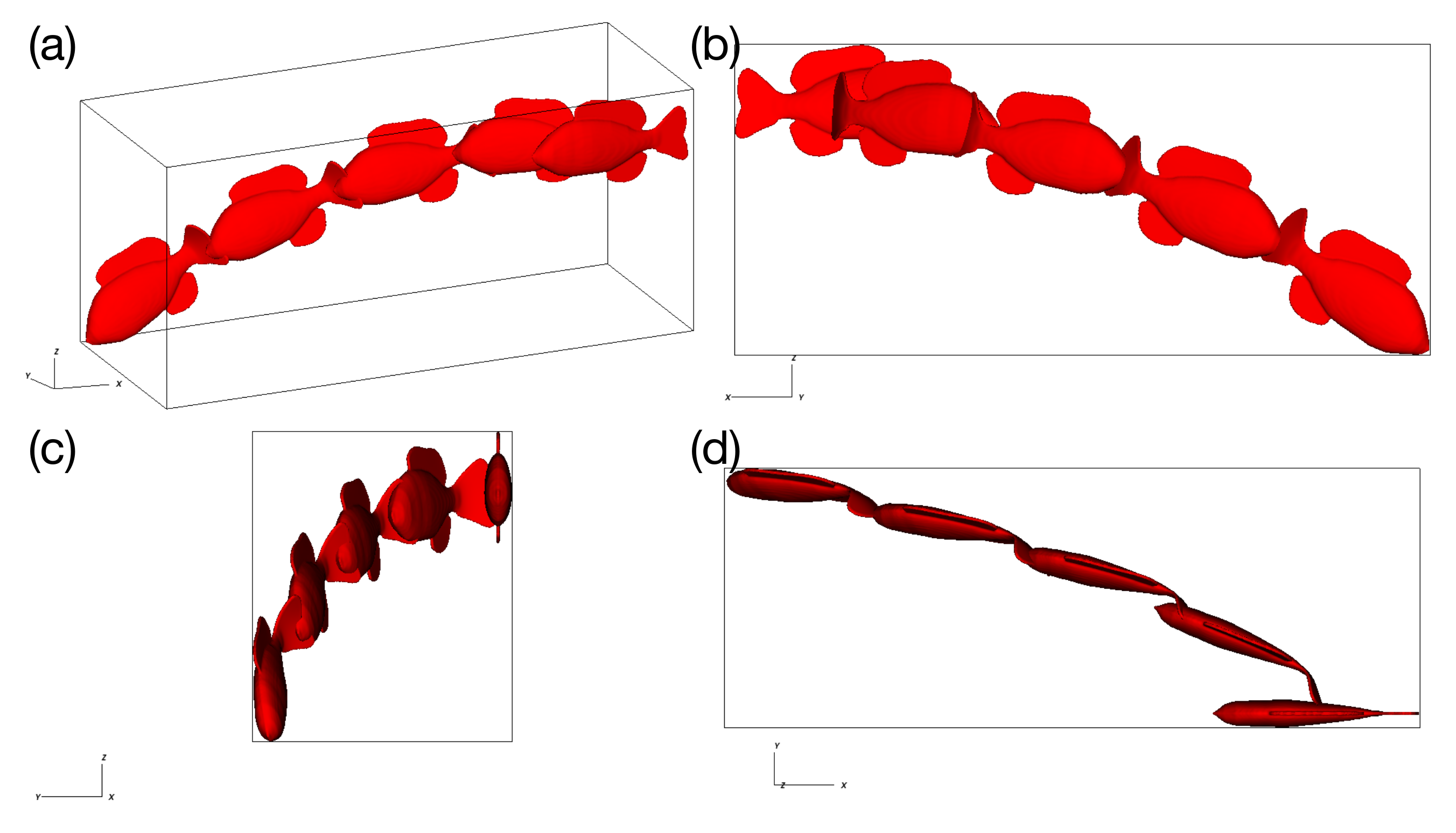
Using the reference values of Table 1 and setting G T ( X , t ) = 0 , the model was actuated with a torque (Equation 11) at a frequency of 0.75 Hz and allowed to swim in an unconstrained manner for 10 actuation cycles. Figure 2 shows that the trajectory of the fish does not stabilize, even after 10 cycles.
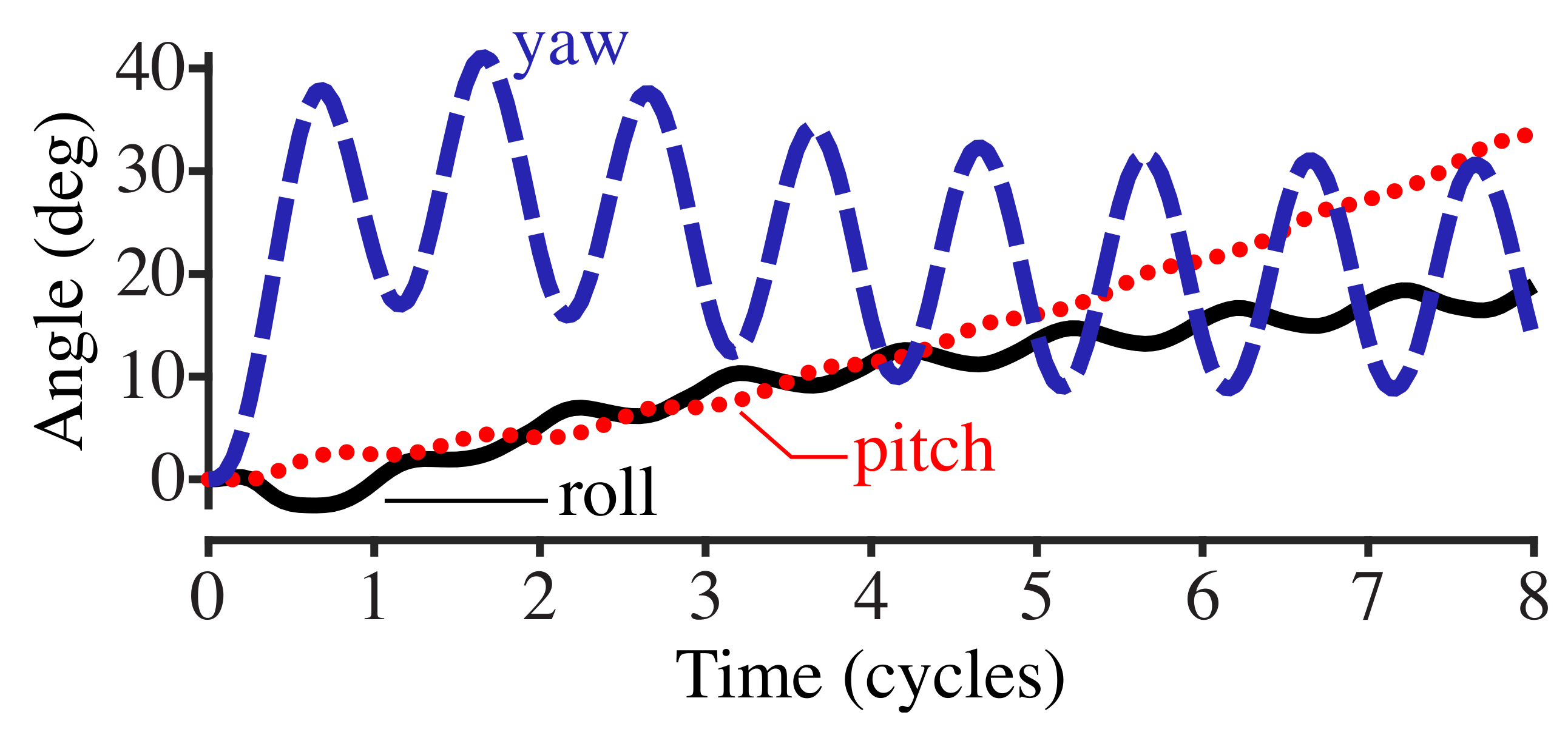
Figure 3 shows the roll, pitch, and yaw angles (see Section 2.4) with respect to the cycle phase of the driving torque. The yaw of the body, which is in the same plane as the applied torque of G F , oscillates with the driving torque frequency. Roll and pitch diverge at an increasing rate as time increases.
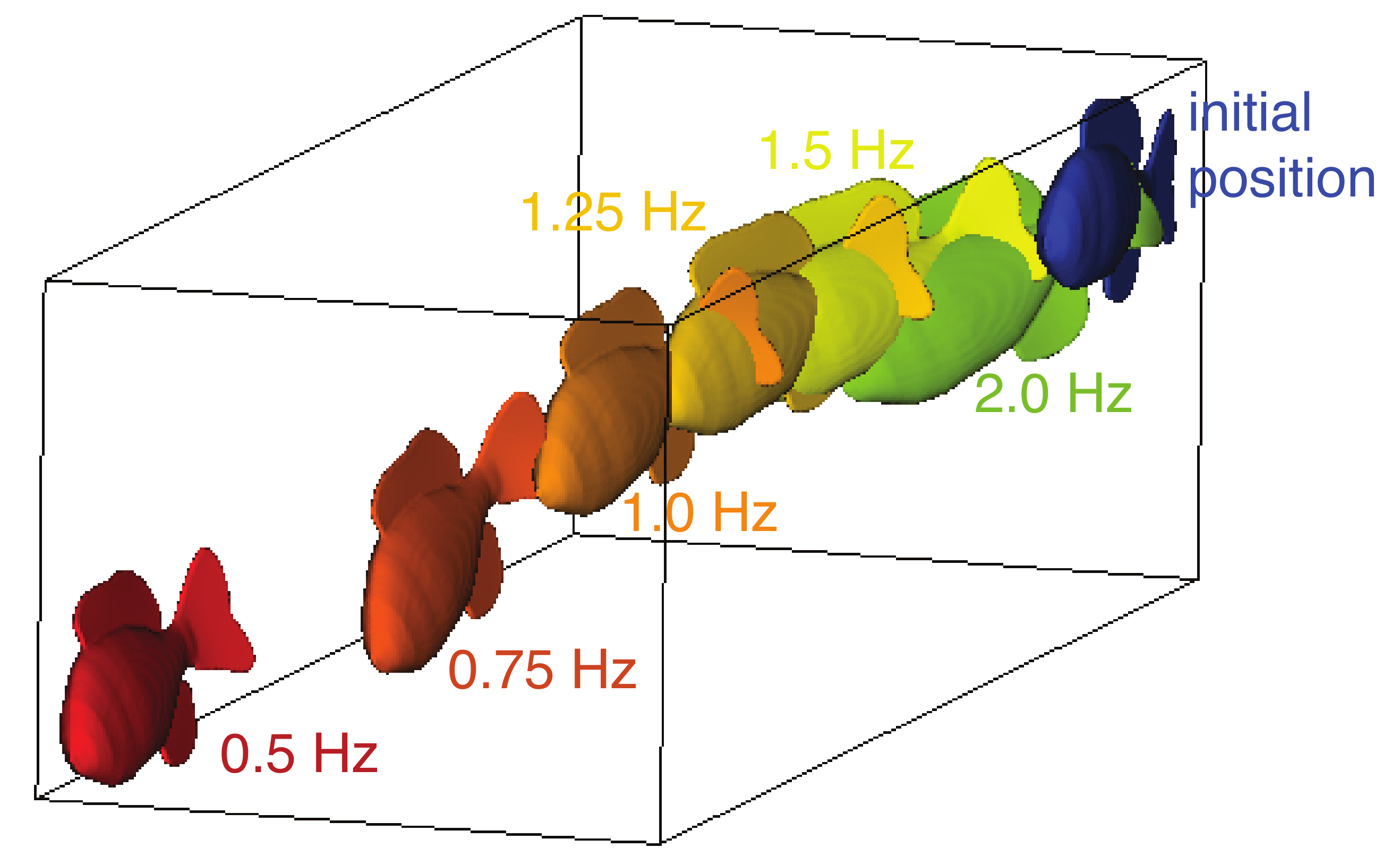
The trajectory of the swimmer depends on the actuation frequency. In Figure 4, we plotted the end position of the fish model after eight actuation cycles for swimmers with six frequencies, f = 0.5, 0.75, 1.0, 1.25, 1.5 and 2.0 Hz. As the frequencies increased, the trajectory veers increasingly to the side and rolls and pitches further downward. This suggests that the resulting trajectory is a function of the actuation frequency and the material properties of the model.

3.2. Stabilizing Torque

We then examine the stabilizing forces of the constrained fish model. Figure 5 shows the stabilizing roll and pitch torques with respect to cycle phase. The oscillations have a non-zero mean, indicating that the unconstrained fish would not remain on the x y -plane, but they are consistent over more than three cycles for both torques, suggesting that a steady state swimming pattern has emerged.
The roll and pitch torques needed to stabilize the model vary with driving frequency in a non-monotonic way over actuation frequencies from 0.5 to 1.25 Hz in 0.25 Hz increments. The stabilizing roll and pitch torque both vary periodically at all driving frequencies (Figure 5a,b), but with different amplitudes and timing of the peaks with respect to the cycle phase. The amplitude of roll torque increases with actuation frequency (Figure 5a), while the pitch torque amplitude remains approximately constant (Figure 5b). The peak amplitude for both roll and pitch shifts in the phase of the actuation cycle according to actuation frequency. As the frequency increases, the peak roll torque occurs later in the phase, while the peak pitch torque varies in a more complex way.
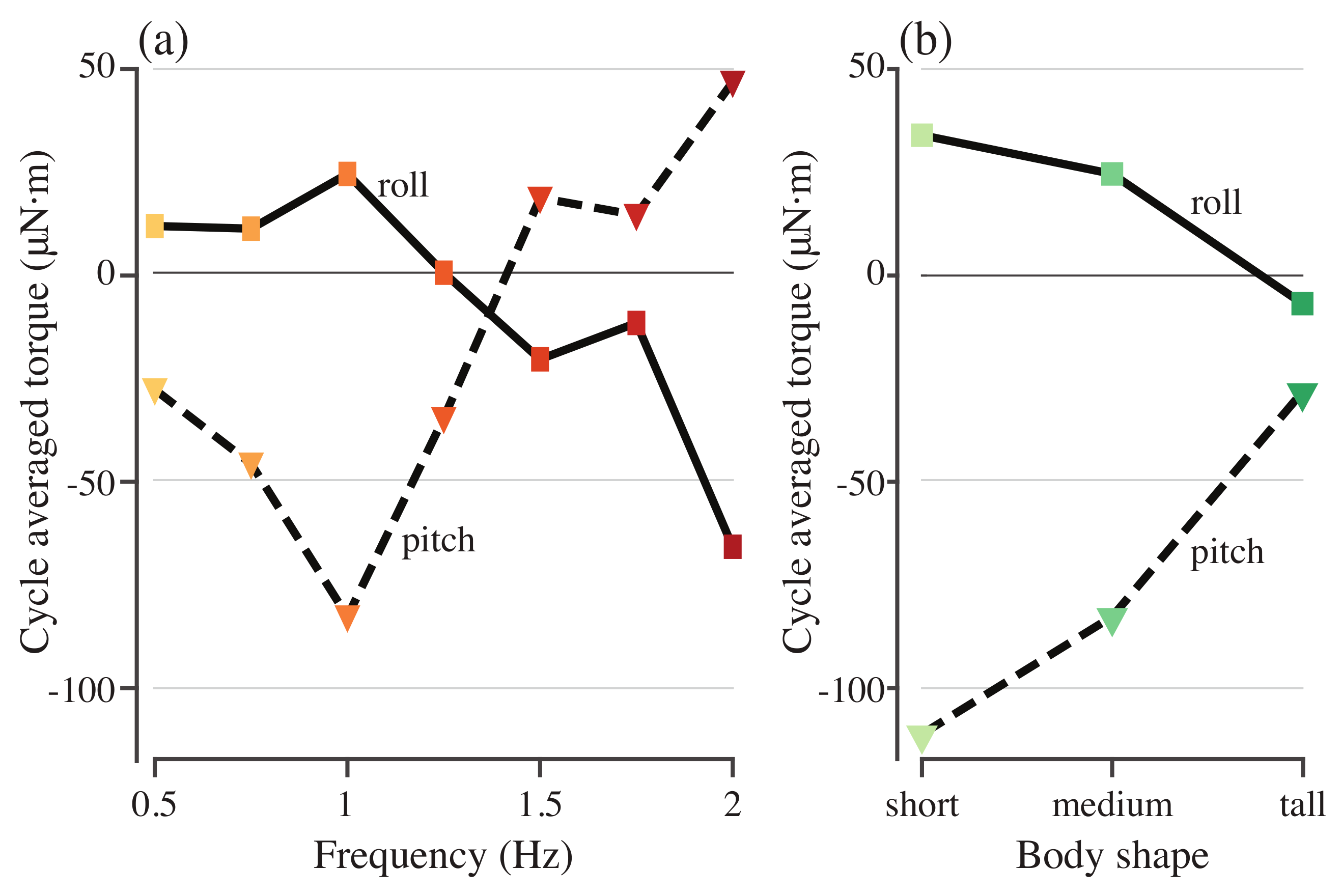
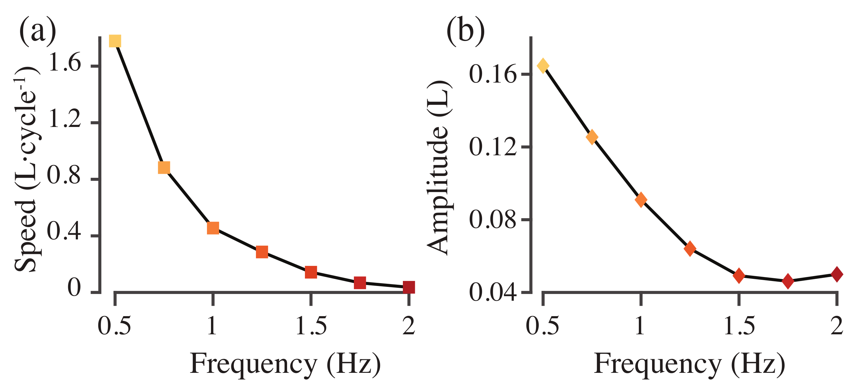
Figure 6a shows the cycle-averaged roll and pitch torques required to stabilize the model with different driving frequencies. None of the torques average to zero. As the actuation frequency increases, the roll torque is small and positive before decreasing and changing sign at f = 1.5 Hz (Figure 6a), while the pitch torque initially increases in magnitude before changing sign, again at f = 1.5 Hz (Figure 6a). Swimming speed in body lengths per tail beat cycle decreases as actuation frequency increases (Figure 7). Tail beat amplitude also decreases until f = 1.75 Hz but then begins to increase again at 2.0 Hz (Figure 7).

3.3. Varying Body Shape

To understand the role of geometry in determining the roll and pitch torques, the simulation was run for bodies that were 25% taller and shorter than the original body. The actuating torque was driven at a frequency of 0.75 Hz with a force magnitude scaled by the height of the body. Figure 8 shows the stabilizing roll and pitch torques for each of the three body geometries. Cycle-averaged roll and pitch torques decreased in magnitude as body height increased (Figure 6b). For both roll and pitch, the shorter body required much higher-magnitude torque to stabilize it on average, but the taller body had a larger fluctuation in the stabilizing torque (Figure 8a,b).

4. Discussion

Many fish swim by producing thrust with their caudal fin [32,33], a mode called body-caudal fin swimming [34]. The center of pressure for thrust is therefore behind the center of mass: a potentially unstable configuration [6]. Moreover, the dorsal and anal fins are not perfectly symmetric and do not produce the same flow patterns [4,9], suggesting that their torques do not balance each other: again, a potentially unstable configuration.
Despite recognizing these instabilities for a long time [6], researchers have not generally quantified them. This has been challenging for several reasons. The first challenge is that, despite the prediction of instability, fish do swim stably. This observation suggests either the caudal fin thrust and body asymmetries are not actually unstable, or, more likely, that fish are constantly stabilizing themselves. They may adjust the caudal fin beat or use their pectoral fins or other fins to maintain upright forward movement. Based on neural recordings from lampreys, we know that fish maintain upright orientation by a cycle-by-cycle modulation of the body and tail motion [35] and that, without their vestibular system, they roll continuously [36]. However, identifying which body and fin motions are related to propulsion and which are related to stability is very challenging and may not always be possible [36].
A second reason that quantifying instability in swimming fishes is hard is that quantifying instability in general is hard [12]. Unstable systems, by definition, diverge, which usually invalidates the approximations used to assess stability.
Here, we developed a new way to quantify instability in fishes using a computational model. We simulated a simple model of a swimming fish that matches many features of the mechanics and kinematics of real swimming fishes. The model is homogeneously elastic. Although fish bodies have complex internal anatomy [1,37] with many nonlinear materials (e.g., [38]), describing them as homogeneous beams may be a good first approximation [39,40]. We also actuate the model at one vertical axis, as if it was being twisted back and forth on a stick. Again, this approximation does not include any of the complexity of fish muscle [41,42], but rubber fish models mounted in this way actually match many features of the body motions of swimming fishes [28,43].
This model, as expected, does not maintain a stable heading or upright orientation (Figure 2 and Figure 3). This supports the hypothesis that caudal fin propulsion in fishes is unstable and requires active stabilization. Stabilizing forces likely come from the pectoral or pelvic fins, or the dorsal or anal fins. They could even come from small adjustments in the caudal fin shape or motion. For example, the conformation of the caudal fin is controlled actively by small muscles at the base of the fin rays [44], and fish can alter the shape fairly dramatically during different behaviors [45].
When we add stabilizing torques, we find that they fluctuate during the fin beat cycle and do not average to zero (Figure 6). This observation again supports the idea that caudal fin propulsion is unstable, and indicates that our unconstrained fish model would never reach a stable state, but would continue to spiral in roll and pitch, as seen in Figure 4. The sign of the corrective torque is arbitrary, and is set by the initial transient, depending on whether the fish starts beating its tail to the left or the right. If we mirror the fish and its driving torque, the cycle-averaged patterns seen in Figure 6 are the same, but have the opposite sign.
The stability of the fish model depends on both the driving frequency and the shape of the body. Flexible panels driven sinusoidally have nonlinear resonance patterns in both swimming speed and trailing edge amplitude [16,46], with multiple peaks that depend on the driving frequency, body stiffness, and shape. Specifically, the nonlinearities depend on the effective flexibility of the body,
Π = ρ s L 5 f 2 E I
where s is the height of the body, L is body length, f is driving frequency, and E I is the bending modulus. We find nonlinear patterns in roll and pitch torque as a function of frequency (Figure 6). These nonlinearities may also be part of this resonant pattern, where resonant peaks in tail beat amplitude correspond to more stable or less stable swimming. Indeed, in these models, tail beat amplitude decreases and then increases again (Figure 7b), which may be part of a resonant interaction similar to the one we saw in [16].
We only tested three different body shapes, so if there is a similar nonlinearity in stability as a function of body shape, it would be hard to see from our results. However, even with our limited sampling, the medium body height model requires a lower amplitude corrective roll torque than the short and tall models (Figure 8a). These models are perfectly neutrally buoyant, so these differences do not reflect differences in the locations of the center of mass and center of buoyancy. When we scaled the models to produce the different body shapes, we also scaled the fins, but the dorsal and anal fin are asymmetric and both fins are flexible. There may therefore be differences in how they bend that alter the centers of pressure that affect the stability of the different body shapes. Further work would be useful to examine how passive stability depends on the size and shape of the fins, separately from that of the body.
In conclusion, we have developed a simple way of assessing the stability of swimming fish models by computing the corrective torques required to maintain an upright orientation. In real fish, these torques would have to be produced by fins other than the caudal fin or by subtle modifications of the caudal fin shape or motion, patterns that are difficult to detect or quantify. Our new technique will allow us to examine the intrinsic stability and its inverse— maneuvering ability [6]—in fish models with different shapes, swimming speeds, and swimming modes.

Author Contributions

E.T. and A.P.H. designed the study; A.P.H. developed computational models and analyzed data; E.T. and A.P.H. wrote the paper; E.T. obtained funding for the research. All authors have read and agreed to the published version of the manuscript.

Funding

This work has been supported by NSF grant IOS 1652582 to E.T.

Conflicts of Interest

The authors declare no conflict of interest.

References

  1. Videler, J.J. Fish Swimming; Chapman and Hall: London, UK, 1993. [Google Scholar]
  2. Webb, P.W. Control of Posture, Depth, and Swimming Trajectories of Fishes. Integr. Comp. Biol. 2002, 42, 94–101. [Google Scholar] [CrossRef] [PubMed]
  3. Standen, E.M.; Lauder, G.V. Hydrodynamic Function of Dorsal and Anal Fins in Brook Trout (Salvelinus Fontinalis). J. Exp. Biol. 2007, 210, 325–339. [Google Scholar] [CrossRef] [PubMed] [Green Version]
  4. Tytell, E.D. Median fin function in bluegill sunfish, Lepomis macrochirus: Streamwise vortex structure during steady swimming. J. Exp. Biol. 2006, 209, 1516–1534. [Google Scholar] [CrossRef] [PubMed] [Green Version]
  5. Webb, P.W.; Weihs, D. Hydrostatic Stability of Fish with Swim Bladders: Not All Fish Are Unstable. Can. J. Zool. 1994, 72, 1149–1154. [Google Scholar] [CrossRef]
  6. Webb, P.W. Stability and Maneuverability. In Fish Biomechanics; Academic Press: San Diego, CA, USA, 2005; Volume 23, pp. 281–332. [Google Scholar]
  7. Lauder, G.V.; Madden, P.G.A.; Mittal, R.; Dong, H.; Bozkurttas, M. Locomotion with Flexible Propulsors: I. Experimental Analysis of Pectoral Fin Swimming in Sunfish. Bioinspiration Biomimetics 2006, 1, S25–S34. [Google Scholar] [CrossRef]
  8. Standen, E.M. Pelvic Fin Locomotor Function in Fishes: Three-Dimensional Kinematics in Rainbow Trout (Oncorhynchus Mykiss). J. Exp. Biol. 2008, 211, 2931–2942. [Google Scholar] [CrossRef] [Green Version]
  9. Tytell, E.D.; Standen, E.M.; Lauder, G.V. Escaping Flatland: Three-Dimensional Kinematics and Hydrodynamics of Median Fins in Fishes. J. Exp. Biol. 2008, 211, 187–195. [Google Scholar] [CrossRef] [Green Version]
  10. Bartol, I.K.; Gordon, M.S.; Webb, P.; Weihs, D.; Gharib, M. Evidence of Self-Correcting Spiral Flows in Swimming Boxfishes. Bioinspir. Biomim. 2008, 3, 014001. [Google Scholar] [CrossRef] [Green Version]
  11. Trinci, G.; Harvey, G.L.; Henshaw, A.J.; Bertoldi, W.; Hölker, F. Life in Turbulent Flows: Interactions between Hydrodynamics and Aquatic Organisms in Rivers. Wiley Interdiscip. Rev. Water 2017, 4, e1213. [Google Scholar] [CrossRef]
  12. Guckenheimer, J.M.; Holmes, P.J. Nonlinear Oscillations, Dynamical Systems, and Bifurcations of Vector Fields; Springer: New York, NY, USA, 1983. [Google Scholar]
  13. Stevens, L.M.; Blob, R.W.; Mayerl, C.J. Ontogeny, Morphology and Performance: Changes in Swimming Stability and Turning Performance in the Freshwater Pleurodire Turtle, Emydura Subglobosa. Biol. J. Linn. Soc. 2018, 125, 718–729. [Google Scholar] [CrossRef]
  14. Tytell, E.D.; Hsu, C.Y.; Williams, T.L.; Cohen, A.H.; Fauci, L.J. Interactions between Internal Forces, Body Stiffness, and Fluid Environment in a Neuromechanical Model of Lamprey Swimming. Proc. Natl. Acad. Sci. USA 2010, 107, 19832–19837. [Google Scholar] [CrossRef] [PubMed] [Green Version]
  15. Hamlet, C.; Fauci, L.J.; Tytell, E.D. The Effect of Intrinsic Muscular Nonlinearities on the Energetics of Locomotion in a Computational Model of an Anguilliform Swimmer. J. Theor. Biol. 2015, 385, 119–129. [Google Scholar] [CrossRef] [PubMed] [Green Version]
  16. Hoover, A.P.; Cortez, R.; Tytell, E.D.; Fauci, L.J. Swimming Performance, Resonance, and Shape Evolution in Heaving Flexible Panels. J. Fluid Mech. 2018, 847, 386–416. [Google Scholar] [CrossRef] [Green Version]
  17. Hamlet, C.; Santhanakrishnan, A.; Miller, L.A. A Numerical Study of the Effects of Bell Pulsation Dynamics and Oral Arms on the Exchange Currents Generated by the Upside-down Jellyfish Cassiopea Xamachana. J. Exp. Biol. 2011, 214, 1911–1921. [Google Scholar] [CrossRef] [Green Version]
  18. Hoover, A.; Miller, L. A Numerical Study of the Benefits of Driving Jellyfish Bells at Their Natural Frequency. J. Theor. Biol. 2015, 374, 13–25. [Google Scholar] [CrossRef]
  19. Hoover, A.P.; Griffith, B.E.; Miller, L.A. Quantifying Performance in the Medusan Mechanospace with an Actively Swimming Three-Dimensional Jellyfish Model. J. Fluid Mech. 2017, 813, 1112–1155. [Google Scholar] [CrossRef]
  20. Battista, N.A.; Baird, A.J.; Miller, L.A. A Mathematical Model and MATLAB Code for Muscle-Fluid-Structure Simulations. Integr. Comp. Biol. 2015, 55, 901–911. [Google Scholar] [CrossRef] [Green Version]
  21. Zhang, C.; Guy, R.D.; Mulloney, B.; Zhang, Q.; Lewis, T.J. Neural Mechanism of Optimal Limb Coordination in Crustacean Swimming. Proc. Natl. Acad. Sci. USA 2014, 111, 13840–13845. [Google Scholar] [CrossRef] [Green Version]
  22. Miller, L.A.; Peskin, C.S. When Vortices Stick: An Aerodynamic Transition in Tiny Insect Flight. J. Exp. Biol. 2004, 207, 3073–3088. [Google Scholar] [CrossRef] [Green Version]
  23. Jones, S.; Laurenza, R.; Hedrick, T.L.; Griffith, B.E.; Miller, L.A. Lift vs. Drag Based Mechanisms for Vertical Force Production in the Smallest Flying Insects. J. Theor. Biol. 2015, 384, 105–120. [Google Scholar] [CrossRef] [Green Version]
  24. Mittal, R.; Iaccarino, G. Immersed Boundary Methods. Annu. Rev. Fluid Mech. 2005, 37, 239–261. [Google Scholar] [CrossRef] [Green Version]
  25. Peskin, C.S. The Immersed Boundary Method. Acta Numer. 2002, 11, 479–517. [Google Scholar] [CrossRef] [Green Version]
  26. Griffith, B.E.; Patankar, N.A. Immersed methods for fluid–structure interaction. Annu. Rev. Fluid Mech. 2020, 52, 421–448. [Google Scholar] [CrossRef] [PubMed] [Green Version]
  27. Griffith, B.E.; Luo, X. Hybrid Finite Difference/Finite Element Immersed Boundary Method. Int. J. Numer. Methods Biomed. Eng. 2017, 33, e2888. [Google Scholar] [CrossRef] [PubMed] [Green Version]
  28. McHenry, M.J.; Pell, C.A.; Long, J.H. Mechanical Control of Swimming Speed: Stiffness and Axial Wave Form in Undulating Fish Models. J. Exp. Biol. 1995, 198, 2293–2305. [Google Scholar] [PubMed]
  29. Diebel, J. Representing Attitude: Euler Angles, Unit Quaternions, and Rotation Vectors. Matrix 2006, 58, 1–35. [Google Scholar]
  30. IBAMR. IBAMR: An Adaptive and Distributed-Memory Parallel Implementation of the Immersed Boundary Method. 2014. Available online: https://github.com/IBAMR/IBAMR (accessed on 21 September 2020).
  31. Griffith, B.E.; Hornung, R.D.; McQueen, D.M.; Peskin, C.S. An Adaptive, Formally Second Order Accurate Version of the Immersed Boundary Method. J. Comput. Phys. 2007, 223, 10–49. [Google Scholar] [CrossRef]
  32. Lighthill, M.J. Aquatic Animal Propulsion of High Hydromechanical Efficiency. J. Fluid Mech. 1970, 44, 265–301. [Google Scholar] [CrossRef]
  33. Lucas, K.N.; Lauder, G.V.; Tytell, E.D. Airfoil-like Mechanics Generate Thrust on the Anterior Body of Swimming Fishes. Proc. Natl. Acad. Sci. USA 2020. [Google Scholar] [CrossRef]
  34. Lauder, G.V.; Tytell, E.D. Hydrodynamics of Undulatory Propulsion. Fish Physiol. 2005, 23, 425–468. [Google Scholar]
  35. Zelenin, P.V.; Grillner, S.; Orlovsky, G.N.; Deliagina, T.G. The Pattern of Motor Coordination Underlying the Roll in the Lamprey. J. Exp. Biol. 2003, 206, 2557–2566. [Google Scholar] [CrossRef] [Green Version]
  36. Ullén, F.; Deliagina, T.G.; Orlovsky, G.N.; Grillner, S. Spatial Orientation in the Lamprey. 1. Control of Pitch and Roll. J. Exp. Biol. 1995, 198, 665–673. [Google Scholar]
  37. Summers, A.P.; Long, J.H. Skin and Bones, Sinew and Gristle: The Mechanical Behavior of Fish Skeletal Tissues. In Fish Physiology; Shadwick, R.E., Lauder, G.V., Eds.; Elsevier: Amsterdam, The Netherland, 2005; Volume 23, pp. 141–177. [Google Scholar]
  38. Tytell, E.D.; Carr, J.A.; Danos, N.; Wagenbach, C.; Sullivan, C.M.; Kiemel, T.; Cowan, N.J.; Ankarali, M.M. Body Stiffness and Damping Depend Sensitively on the Timing of Muscle Activation in Lampreys. Integr. Comp. Biol. 2018, 58, 860–873. [Google Scholar] [CrossRef] [PubMed]
  39. Long, J.H.; Adcock, B.; Root, R.G. Force Transmission via Axial Tendons in Undulating Fish: A Dynamic Analysis. Comp. Biochem. Physiol. A 2002, 133, 911–929. [Google Scholar] [CrossRef]
  40. Coughlin, D.J.; Valdes, L.; Rome, L.C. Muscle Length Changes during Swimming in Scup: Sonomicrometry Verifies the Anatomical High-Speed Cine Technique. J. Exp. Biol. 1996, 199, 459–463. [Google Scholar]
  41. Shadwick, R.E.; Gemballa, S. Structure, Kinematics, And Muscle Dynamics In Undulatory Swimming. In Fish Biomechanics; Shadwick, R.E., Lauder, G.V., Eds.; Elsevier Academic Press: San Diego, CA, USA, 2006; Volume 23, pp. 241–280. [Google Scholar]
  42. Gemballa, S.; Vogel, F. The Spatial Arrangement of White Muscle Fibers and Myoseptal Tendons in Fishes. Comp. Biochem. Physiol. A 2002, 133, 1013–1037. [Google Scholar] [CrossRef]
  43. Root, R.G.; Courtland, H.W. Swimming Fish and Fish-like Models: The Harmonic Structure of Undulatory Waves Suggests That Fish Actively Tune Their Bodies. In International Symposium on Unmanned Untethered Submersible Technology; University of New Hampshire-Marine Systems Engineering Laboratory: Durham, NH, USA, 1999; pp. 378–388. [Google Scholar]
  44. Flammang, B.E.; Alben, S.; Madden, P.G.A.; Lauder, G.V. Functional Morphology of the Fin Rays of Teleost Fishes. J. Morphol. 2013, 274, 1044–1059. [Google Scholar] [CrossRef] [Green Version]
  45. Flammang, B.E.; Lauder, G.V. Caudal Fin Shape Modulation and Control during Acceleration, Braking and Backing Maneuvers in Bluegill Sunfish, Lepomis Macrochirus. J. Exp. Biol. 2009, 212, 277–286. [Google Scholar] [CrossRef] [Green Version]
  46. Alben, S.; Witt, C.; Baker, T.V.; Anderson, E.; Lauder, G.V. Dynamics of Freely Swimming Flexible Foils. Phys. Fluids 2012, 24, 051901. [Google Scholar] [CrossRef] [Green Version]
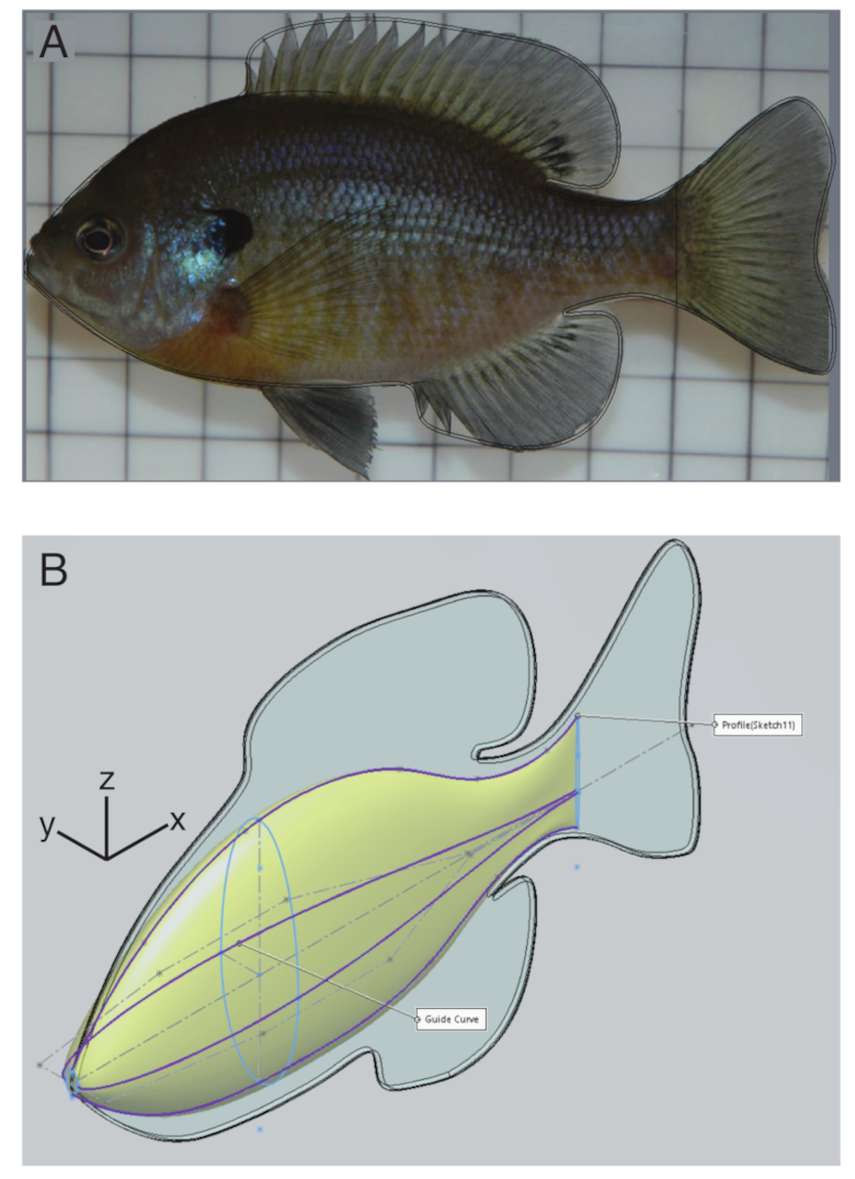
Figure 1. Body construction. (A) Fins were traced (black line) from a lateral image of a bluegill sunfish. (B) The body was constructed by smoothly changing the width and height of an ellipse (light blue), based on guide curves (purple).
Fluids 05 00215 g001
Figure 2. The trajectory over 10 actuation cycles of the unconstrained model using reference material parameters, with (a) an isometric view, (b) the view of the x z -plane, (c) the view of the y z -plane, and (d) the view from the x y plane.
Fluids 05 00215 g002
Figure 3. Plot of the roll, pitch, and yaw of the fish body with respect to the cycle phase. The fish body is driven by an applied torque with a frequency of 0.75 Hz.
Fluids 05 00215 g003
Figure 4. The end position of the fish model after eight actuation cycles for f = 0.5 Hz (red), 0.75 Hz (red-orange), 1.0 Hz (orange), 1.25 Hz (yellow-orange), 1.5 Hz (yellow), and 2.0 Hz (green). Initial position in blue.
Fluids 05 00215 g004
Figure 5. Pitch and roll torques needed to stabilize models with different driving frequencies. Roll (a) and pitch (b) torque for stabilization for swimmers with driving frequencies from 0.5 to 2.0 Hz.
Fluids 05 00215 g005
Figure 6. Pitch and roll torques needed to stabilize models with different driving frequencies (a) and different body shapes (b).
Fluids 05 00215 g006
Figure 7. Swimming speed (a) and tail beat amplitude (b) as a function of actuation frequency.
Fluids 05 00215 g007
Figure 8. Pitch and roll torques needed to stabilize models with different body shapes. Roll (a) and pitch (b) torque for stabilization for swimmers with short, medium, and tall bodies.
Fluids 05 00215 g008
Table 1. Parameters used in simulations.
QuantitySymbolReference Value
Fish lengthL10 cm
Fish heighth5.5 cm
Elastic ModulusE 1 × 10 4 Pa
Poisson ratio η 0.3
Spring constant κ 1 × 10 7 Pa
Max force magnitude F m a x 7.5 × 10 5 N
Numerical timestep Δ t 2 × 10 4 s
Domain widthW0.6 m
Grid stepsizeh W / 1024
Publisher’s Note: MDPI stays neutral with regard to jurisdictional claims in published maps and institutional affiliations.