Article

Re-Entrant Corner for a White-Metzner Fluid

1
School of Mathematics and Statistics, University of Sheffield, Hicks Building, Hounsfield Road, Sheffield S3 7RH, UK
2
Department of Chemical and Biological Engineering, University of Sheffield, Mappin Street, Sheffield S1 4NL, UK
*
Author to whom correspondence should be addressed.
Current address: School of Mathematics, University of Leeds, Leeds LS2 9JT, UK.
These authors contributed equally to this work.
Fluids 2021, 6(7), 241; https://doi.org/10.3390/fluids6070241
Submission received: 24 May 2021 / Revised: 29 June 2021 / Accepted: 30 June 2021 / Published: 2 July 2021
(This article belongs to the Collection Non-Newtonian Fluid Mechanics)

Abstract

:
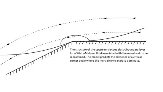
Viscoelastic fluids can be difficult to model due to the wide range of different physical behaviors that polymer melts can exhibit. One such feature is the viscous elastic boundary layer. We address the particular problem of a viscoelastic shear-dependent fluid flowing past a corner and investigate how the properties of the boundary layer change for a White-Metzner fluid. The boundary layer equations are derived and the upstream layer is matched with the far-field flow. It was found that if the fluid is sufficiently shear thinning then the viscoelastic boundary layer formulation fails due to the inertial forces becoming dominant. The depth of the boundary layer is controlled by the shear-thinning parameters. These effects are not a feature of other shear-thinning models, such as the Phan-Thien-Tanner model. This study provides insight in the different effects of some commonly used viscoelastic models in corner flows in the upstream boundary layer, the downstream boundary layer is not addressed.

Graphical Abstract

1. Introduction

Boundary layers have been well-studied for Newtonian fluids since the paradigm shifting work of Prandtl [1]. However, boundary layer structures are also ubiquitously found in non-Newtonian fluids due to the myriad of complex competing behaviors, such as those arising from the competing effects of viscoelasticity and viscosity [2,3].
The classic geometry in which to study viscoelastic boundary layer effects is the re-entrant corner, although wedge flows [4] have also been studied. Re-entrant flows arise in many rheological applications, for example, in cross-slot and upstream contraction geometries [5,6]. Initial numerical simulations of re-entrant corner flows for viscoelastic fluids were compromised due to poor numerical convergence [7]. Corner smoothing can be applied to overcome this, the effects of which have been quantified [8,9]. The first analytical approach for investigating the properties of viscoelastic stresses in corner flows was presented by Lipscomb et al. [10] for the case of a second order fluid, although this model is invalid in regimes with large velocity gradients. Other approaches have been based on a decoupling of the velocity field from the constitutive relation [11,12] to give insight into the structure of the stress singularity.
It is only since the seminal work of Renardy [13] that these boundary layer structures have started to become well-understood. Renardy argued that the local breakdown in the purely affine deformation is due to the no-slip condition sufficiently reducing the local Weissenberg number so that the viscous terms are of parity with the elastic terms. The boundary layer equations for an upper-convective Maxwell (UCM) fluid were derived and solved numerically upstream of the corner. The difficulties associated with analyzing the boundary layer downstream of the corner were addressed later [14,15].
The UCM model studied in Renardy [16] is a relatively simple viscoelastic model. Evans [17] generalized Renardy’s analysis to consider an Oldroyd B fluid, thus physically accounting for solvent viscous effects not included in the UCM model. It was found that an Oldroyd B and UCM fluids exhibit similar features unless the retardation time is close to the relaxation time.
The UCM and Oldroyd B models are regarded as being accurate only for predicting the behavior of Boger fluids [18,19] as they do not exhibit the shear-dependent viscous behavior that generally occurs in polymer melts. The first studies to incorporate shear-thinning effects with viscoelasticity for the re-entrant problem were performed by Sibley and Evans [20,21,22] for the case of a Phan-Thien-Tanner (PTT) fluid. It was found that as a result of the shear-thinning behavior, the velocity field decays at a slower rate compared to the Newtonian case. The stress and velocity singularities could still be expressed as functions of the corner angle, α , only. The Giesekus model, which also exhibits shear-thinning viscoelastic behavior, does not permit the same boundary layer structure as the PTT model [22].
In this article, we derive the boundary layer equations for a White-Metzner (WM) fluid [23] and analyze the structure of the boundary layer. Unlike the PTT and Giesekus models, the WM model is linear with respect to the stress tensor and the parameters can be adjusted to model both shear-thinning and shear-thickening behaviors, although shear-thinning effects are the more common response in viscous melts. Metzner and Whitlock [24] first reported viscoelastic shear-thickening behavior for a suspension of titanium dioxide in a sucrose solution. Viscoelastic shear thickening behavior has since been found to occur for a variety of suspensions [25,26]. Direct comparisons of the PTT, Giesekus, and WM models found that the WM model generally gave rise to the best predictions, although it did not accurately predict the uni-axial extensional viscosity [27].
The applicability of the WM model in re-entrant corner geometries has been investigated numerically in an upstream contraction [28,29]. Sousa et al. [30] studied bifurcations of polyacrylamide and polyethylene oxide in a water glycerol solvent, which was fitted to a WM model. However, a complete analytical description of the WM model around a re-entrant corner geometry has yet to be explicitly studied. This gives the motivation for this work. Determination of the scales and constraints for such boundary layers will be of importance for both further numerical and experimental investigations.
The paper is structured as follows. The governing equations are presented in Section 2. Results are presented in Section 3. Conclusions are discussed in Section 4.

2. Materials and Methods

Governing Equations

The geometry of the re-entrant corner problem is shown in Figure 1. Here two semi-infinite rigid plates meet at an angle ϕ = π α . We consider angles constrained by 1 2 < α < 1 which arises from the 2 π periodicity and requirement that there is a reflex angle which will induce a stress singularity in the viscoelastic stresses. The origin of the two-dimensional plane is at the apex of the corner.
The steady state mass and momentum conservation equations for an incompressible fluid can be written as:
· u = 0 , ρ u · u = p + · T ,
where ρ is the density, u is the velocity field, p is the pressure field and T denotes the dyadic stress tensor, the behavior of which is governed by a constitutive relation. For the WM fluid, this can be written as
T + λ γ ˙ T = μ γ ˙ γ ˙ ,
where T is the upper-convected derivative operator of the tensor field T , which for steady state is given by
T = ( u · ) T u T T ( u ) T ,
where D D t is the substantive derivative, u = u j x i is the tensor of the velocity derivatives for the fluid and superscript T denotes the transpose. The rate of strain tensor γ ˙ is given by γ ˙ i j = u i x j + u j x i , where the shear-rate γ ˙ = 1 2 γ ˙ p q γ ˙ p q with summation convention implied. In order to permit similarity solutions we will assume that the functional form of the relaxation time can be written as
λ ( γ ˙ ) = λ 0 γ ˙ q 1 , μ ( γ ˙ ) = K 1 γ ˙ n 1 ,
where K 1 and λ 0 are fixed constants which will be removed by scaling. n and q are the flow behavior indices. In order to reduce the parameter space a common assumption is to take q = n [30,31]. We refer to this as the “Bird equality” as it proves to be a useful reference point for our analysis. However, we do not need to restrict our model to this case. Several studies have found that q n (Table 1).
The parameters n and q can be readily obtained experimentally from shear-rheometry, with n being derived from the viscous shear relation and q from the first normal stress difference shear relation [35]. It should be noted that λ ( γ ˙ ) and μ ( γ ˙ ) could be fitted using a more generalized power-law model, such as a Carreau-type law. A Carreau viscosity model does not permit global similarity solutions in corner geometries [2], nor can it be readily approached analytically. However, these potential short-comings should have no bearing on this study. Due to the singularity in the shear rate which occurs at the apex of the corner, the Carreau model will be well approximated by a power-law relation in our regions of interest.
The WM model reduces to the upper-convective Maxwell model for n = q = 1 and to a power-law fluid model if λ 0 = 0 . Thus, when both conditions are applied it reduces to a Newtonian model. To non-dimensionalize Equations (2) and (6) we introduce the scalings:
x = x ˜ L , u = u ˜ U , T = ρ U 2 T ˜ , p = ρ U 2 p ˜ .
As the re-entrant corner problem has no natural length or velocity scales one is free to choose them as U = L λ 1 q and L = K 1 λ 0 2 n q ρ 1 1 2 , which is equivalent to setting both the Reynolds and Weissenberg numbers to unity. In order to keep the solution as general as possible, throughout the remainder of this paper we will use scaled variables. However, the unscaled variables can be recovered using (5). Of course, a specific case study is needed in order to express the results in dimensional values. The system of equations reduces to
T + γ ˙ q 1 T = γ ˙ n 1 γ ˙ , · u = 0 , 0 = p + · T ,
where the only parameters which cannot be removed are n and q.

3. Results

3.1. Boundary Layer Analysis

Outer Solution

The upper convective derivative is assumed to be dominant in the limit as r 0 but outside of the boundary layer [13], whereby the constitutive relation (2) reduces to
T = 0 .
Equation (7) has an exact solution T = h ( ψ ) 2 u u , where h is an arbitrary function and ψ is the stream-function [11], Renardy [13]. As the analysis is performed in the locality of the corner apex, it is assumed that h = B ψ 1 m , where B is a constant and the power m is to be determined through matching. Neglecting inertia and applying the laws of mass and momentum conservation leads to the classic inviscid Euler equations for the vector quantity v = h ( ψ ) u [13]:
v · v = p , · v = 0 .
As the Euler equations permit potential flow solutions, we write v = ψ ˜ y , ψ ˜ x , where ψ ˜ is a pseudo-streamfunction for v and x , y are defined as being parallel and perpendicular to the upstream boundary (Figure 1). Using the known solution of Laplace’s equation around a corner and combining it with the chain rule and the definition of v we obtain
ψ ˜ = A r α sin ( α θ ) = h ( ψ ) = B ψ 1 m ,
where A and B are constants. After manipulating the constants we can determine that for the outer solution
ψ = h 1 ψ ˜ = C 0 r m α sin m α θ , T 11 = C 1 C 0 2 m m 2 ψ 2 m 2 ψ y 2 ,
T 12 = C 1 C 0 2 m m 2 ψ 2 m 2 ψ y ψ x , T 22 = C 1 C 0 2 m m 2 ψ 2 m 2 ψ x 2 ,
where C 0 , C 1 are constants. The parameter m is still free and is determined through matching this solution to an inner boundary layer located along the upstream boundary θ = 0 . As Cartesian co-ordinates provide a natural way of describing the upstream boundary, we can use the small angle approximations r x , θ y x which give the outer-behavior to match as
ψ C 0 x m α 1 y m , T 11 C 1 x 2 α 2 , T 12 1 α C 1 x α 3 y , T 22 1 α 2 C 1 x 2 α 4 y 2 .
The parameter m is subject to several constraints. The inertialess constraint is required for Equation (8) to hold. In addition, the upper-convective derivative needs to be the dominant term in (2). Both of these conditions impose restrictions on m. Analysis of the balance in the momentum equation gives u · u r 2 α m 3 , p h 2 u 2 r 2 α 2 , and T r 2 α 2 . For inertial effects to be sub-dominant results in constraint I, which is given below. Similarly, for (7) to be a valid outer approximation of from the constitutive relation (7), we require that γ ˙ q 1 T γ ˙ n 1 γ ˙ and γ ˙ q 1 T T , which leads to the inequalities II and III. Constraint IV is the previously stated re-entrant condition on the angle α . In summary the conditions are given by
(I)
m > 1 ,
(II)
α 2 + m ( q n ) < 2 q + 1 n ,
(III)
α < 2 m 1 ,
(IV)
1 2 < α < 1 .
We will a priori assume that the above constraints hold and, thus, match to the affine outer-solution. Once m has been determined we will validate the constraints I through III and discuss any limiting parameter regimes.

3.2. Upstream Boundary Layer

To analyze the boundary layer we follow the approach of Evans [14,36]. Firstly, we require that r be close to zero at the apex of the corner for (7) to be valid whereby we will assume r O ( ε ) . However, there is a breakdown in this solution near the wall θ = 0 , hence we will assume that θ O ( δ / ε ) , from which it follows that 0 < δ ε 1 . If we consider these scales in Cartesian co-ordinates we have x O ( ε ) and y O ( δ ) , thus δ represents the scale of the boundary layer in the y-direction. Motivated by the outer solution, we assume the scalings:
x = ε X , y = δ Y , ψ ε α 1 m δ m Ψ , T 11 ε 2 α 2 T ^ 11 ,
T 12 ε 2 α 3 δ T ^ 12 , T 22 ε 2 α 4 δ 2 T ^ 22 ,
where X, Y, T ^ i j are all O ( 1 ) . Application of these scalings gives rise to the system of equations:
0 = P X + T ^ 11 X + T ^ 12 Y , 0 = P Y + ε 2 α 4 δ T ^ 12 X + T ^ 22 Y , T ^ 11 + ε q α 1 m 1 δ m q 1 Λ ( q ) Ψ Y T ^ 11 X Ψ X T ^ 11 Y 2 2 Ψ X Y T ^ 11 2 2 Ψ X 2 T ^ 12
= 2 ε α 1 m n + 1 2 α δ m n 2 n + 1 Λ ( n ) 2 Ψ X Y T ^ 12 + ε q α 1 m 1 δ q m 1 Λ ( q ) Ψ Y T ^ 12 X Ψ X T ^ 12 Y + 2 Ψ X 2 T ^ 11 2 Ψ Y 2 T ^ 22
= ε 3 2 α + α 1 n m δ m n 2 n 1 Λ ( n ) 2 Ψ Y 2 + δ ε 2 2 Ψ X 2 , T ^ 22 + ε q α 1 m 1 δ q m 1 Λ ( q ) Ψ Y T ^ 22 X Ψ X T ^ 22 Y + 2 2 Ψ X 2 T ^ 12 + 2 2 Ψ X Y T ^ 22
= 2 ε 3 2 α + α 1 n m δ m n 2 n 1 Λ ( n ) 2 Ψ X Y ,
where we employ the notation
Λ ( i ) = 2 Ψ Y 2 + δ ε 2 2 Ψ X 2 2 + 4 δ ε 2 2 Ψ Y X i 1 2 .
By assuming that the scaling is such that the boundary-layer equations retain the highest number of terms, it follows that
ε q α 1 m 1 = δ 1 q m , ε α 1 m n 2 α + 3 = δ 1 + n ( 2 m ) ,
from which we obtain
m = 2 1 α n + 2 α 3 q α n + 2 α q , δ ε n + 3 2 α q n + q .
In the Bird equality, the boundary layer size is the same as that for the UCM case, however, this is not generally so. The size of the layer is a monotonically decreasing function of n for a fixed value of q, and a monotonically decreasing function of q for fixed n. The size of the layer, δ , is bounded between ε 3 2 α < δ < ε . The lower limit has a infimum of ε 2 , and, therefore, the boundary layer grows at most linearly with distance from the corner and at least parabolically. As α < 1 it is important to note that m is a monotonically increasing function of n. We need to verify that our a priori assumptions I to III still hold. The inertial constraint I reduces to
2 2 α + q 3 α 4 2 α < n .
Equation (21) can be used to simplify the above constraint to obtain the dependence on n solely in terms of α :
n > α 1 2 α 3 .
From consideration of constraint IV, we see that (23) is only active for shear-thinning fluids with n < 0.25 . Thus, for n > 0.25 the inertial effects are sub-dominant and are independent of the corner angle in the far field under the Bird equality. It should be noted that this condition will be different for the each of the fluids in Table 1.
Under the Bird equality constraint, II gives rise to the angle inequality α < 1 , however, for n q an additional constraint arises:
n q < 1 1 α .
This constraint is naturally satisfied for q n . In fact this condition only becomes active relative to IV if n < q + 2 . (Note that constraint IV leads us to the condition ( 1 α ) 1 > 2 .) This requires the fluid be shear-thickening. All of the fluids listed in Table 1 satisfy (24). To the best of our knowledge, there are no fluids for which (24) does not hold true. The final constraint to be verified is III , which can be written as q > α 2 1 α . This is naturally satisfied by q > 0 .

3.3. Similarity Solution

As m has been determined and is consistent with the constraints, the system scaling can be written as
x = ε X , y = ε n + 3 2 α q n + q Y , ψ ε 2 n + α 1 + 3 2 α q n + q Ψ , p ε 2 α 2 P T 11 ε 2 α 2 T ^ 11 , T 12 ε 2 n 1 α n + q T ^ 12 , T 22 ε 2 n q 1 α n + q T ^ 22 .
It, therefore, follows that the boundary layer system can be written as
0 = P X + T ^ 11 X + T ^ 12 Y , P Y = 0 , T ^ 11 + 2 Ψ Y 2 q 1 Ψ Y T ^ 11 X Ψ X T ^ 11 Y 2 2 Ψ X Y T ^ 11 2 2 Ψ X 2 T ^ 12 = 0 , T ^ 12 + 2 Ψ Y 2 q 1 Ψ Y T ^ 12 X Ψ X T ^ 12 Y + 2 Ψ X 2 T ^ 11 2 Ψ Y 2 T 22 , = 2 Ψ Y 2 n 1 2 Ψ Y 2 ,
T ^ 22 + 2 Ψ Y 2 q 1 Ψ Y T ^ 22 X Ψ X T ^ 22 Y + 2 2 Ψ X 2 T ^ 12 + 2 2 Ψ X Y T ^ 22 = 2 2 Ψ Y 2 n 1 2 Ψ X Y .
As the system of partial differential equations is invariant under the scaling we seek a similarity solution of the form
χ = X 2 α 3 q n n + q Y , Ψ = X 2 n + α 1 + 3 2 α q n + q f ( χ ) , P = X 2 α 2 p ¯ ( χ ) , T ^ 11 = X 2 α 2 t 11 ( χ ) , T ^ 12 = X 2 α 1 n n + q t 12 ( χ ) , T ^ 22 = X 2 α 1 n q n + q t 22 ( χ ) .
The similarity variable χ can be interpreted as the local Deborah number. Consideration of the local ratio of advection time to the characteristic relaxation time shows that γ ˙ q 1 u · T T x 2 α 3 q n n + q y = χ . To obtain the similarity solution, one can easily integrate the vertical component of the momentum equation to derive that the pressure is a constant, i.e., p ¯ ( χ ) = p 0 . This gives the familiar result that the pressure gradient is independent of the angle θ , which drives the flow in the upstream region yet acts against the flow in the downstream region. The resulting boundary layer system becomes
2 α 1 n + q t 11 p 0 2 α + 3 q + n χ t 11 + t 12 n + q = 0 , α 2 n + 3 α 4 q 2 α + 2 f q 1 t 11 f + f t 11 2 α + 3 q + n + α 1 f q 1
2 α 3 q n χ t 11 + n + q t 12 f q 1 f 1 2 n + q t 11 = 0 , 1 2 n + q 2 f n 1 f + 1 2 χ 2 2 α q + n + 3 q 2 t 11 + 1 2 n + q 2 t 22 f q 1 f + f f q 1 n + 2 3 q α + 4 q 2 2 α q + n + 3 q χ t 11 n α 1 n + q t 12 + f q 1 f t 11 n + 4 q 2 α 5 q + 2 2 q + 1 α + n + 3 q 1 +
f t 12 n + q 2 q + 1 α + n + 3 q 1 f q 1 1 2 n + q 2 t 12 = 0 , n + q t 22 χ 2 α q + 3 q + n t 12 3 2 α q + n χ f q 1 f n + q n 3 q + 2 α + 4 q 2 f t 22 f q 1 + 2 χ n + 3 q + 2 α + 4 q 2 2 α q + n + 3 q t 12 f f q 1 1 2 n + q 2 t 22 + f f q 1 2 q + 1 α + n + 3 q 1 8 q 4 α 2 n 10 q + 4 t 12 + n + q t 22
+ χ n + q n + q 3 2 α | f | n 1 f n + q 2 1 q α + n + 3 q 2 | f | n 1 f = 0 ,
with matching conditions as χ derived from (12):
f C 0 χ 2 1 α n + 2 α 3 q α n + 2 α q , t 11 C 1 , t 12 1 α C 1 χ , t 22 1 α 2 C 1 χ 2 .
The relationship between p 0 and C 1 can be found from (29) and the matching conditions (33) to give p 0 = C 1 2 .

Near Wall Analysis

In order to derive consistent boundary conditions we must perform a local analysis of the system. By seeking a regular power series expansion around χ = 0 under the assumption that p 0 is fixed, one can recover the expressions
f = 1 2 a χ 2 + b 6 χ 3 + c χ 4 + ,
t 11 = 2 a n + q + b 11 χ + c 11 χ 2 ,
t 12 = a n 1 a + b 12 χ + c 12 χ 2 ,
t 22 = 4 1 α a n 1 a n + q χ + c 22 χ 2 ,
where c , b i j and c i j are constants, the expressions for which are given in Appendix A. The constant value of pressure p 0 can be expressed as a function of a and b by
p 0 = 2 a 2 α 1 n + 2 q + 2 a n + q 2 + n n + q b a n 1 2 α 1 n + q .
Equations (34)–(37) prescribe the initial conditions, however, we do not know how well-posed the problem remains. We proceed by considering an eigen-mode analysis around the regular solution. Let f = f ( 0 ) + Δ f ^ and t i j = t i j ( 0 ) + Δ t ^ i j , where f ( 0 ) , t i j ( 0 ) are given by the expressions (34)–(37). Taking order Δ leads to a system of linear ordinary differential equations in f ^ and t ^ i j . Three solutions can be found by searching for a solution in the form of a regular power-series:
f ^ = 1 , t ^ 11 = 4 a | a | n + 2 q 3 1 α n + q 2 α 3 2 | a | q + 1 n 3 α 1 + q 9 7 α + 8 α 1 b n + q 2 n + q n + q 2 , t ^ 12 = 2 | a | n + q 2 1 α n + q 2 α 3 2 a q + 1 α n 8 q α + 8 α + n + 10 q 8 b n n + q n + q 2 , t ^ 22 = 4 a n + q 2 a 2 q α α n 3 q + 1 4 q α 4 α n 5 q + 4 n + q 2 ,
f ^ = χ , t ^ 11 = 4 2 n + q 1 α a 2 a n + 2 q 3 n + q , t ^ 12 = 2 α n 2 q α + 2 α + 3 q 2 a a n + q 2 n + q , t ^ 22 = 2 2 q α 2 α n 3 q + 2 a n 1 n + q , f ^ = χ 2 , t ^ 11 = 4 n + q a q + n 2 a , t ^ 12 = 2 n a n 1 , t ^ 22 = 4 a n 1 q 1 n 2 α 3 + n 2 n 2 α + 2 n + q χ .
The remaining two independent solutions have an irregular singular point at χ = 0 and can be found by the method of dominant balance to give
f ^ = x r 0 + 5 exp n + q | a | 1 q n + 3 q 1 2 q 1 α a χ , t ^ 11 S 1 x r 0 exp n + q | a | 1 q n + 3 q 1 2 q 1 α a χ , t ^ 12 S 2 x r 0 + 1 exp n + q | a | 1 q n + 3 q 1 2 q 1 α a χ , t ^ 22 S 3 x r 0 + 1 exp n + q | a | 1 q n + 3 q 1 2 q 1 α a χ , f ^ = o x r 1 + 6 exp n + q | a | 1 q n + 3 q 1 2 q 1 α a χ , t ^ 11 x r 1 exp n + q | a | 1 q n + 3 q 1 2 q 1 α a χ , t ^ 12 2 α + 3 q + n n + q x r 1 + 1 exp n + q | a | 1 q n + 3 q 1 2 q 1 α a χ , t ^ 22 S 4 x r 1 + 2 exp n + q | a | 1 q n + 3 q 1 2 q 1 α a χ .
Here
r 0 = { 6 n n + q a 1 q b n n + q 2 a 2 q 48 n 1 3 2 α q + n + α 1 3 2 α q + n + 2 α 2 a } / 12 3 2 α q + n + α 1 1 4 n + q n | a | 1 q + n 1 n + 3 2 α q + 2 α 1 a , r 1 = 6 a 2 α 12 a 2 b n + 18 a 2 α 24 a 2 b q 12 a 2 α 1 a 2 2 α 3 q + 1 α n .
The constants S i are given in Appendix B. Let us assume that n + 3 q + 1 ( 2 q 1 ) α > 0 , which imposes no additional constraints on the system (see Appendix C for details). We see that the irregular solutions mirror the same behavior as those found for the UCM case [14] for all n , q > 0 , thus we conclude that the first and second modes are inconsistent with local viscometric behavior. The third mode is always consistent with the local viscometric behavior and can be determined by imposing a, thus giving one degree of freedom. The final two modes are consistent with the asymptotic condition for a < 0 and inconsistent when a > 0 , independent of n and q. Thus, there are three degrees of freedom when a < 0 and one degree of freedom for a > 0 . The consequence of this is that the upstream problem is well-posed with use of (34)–(37) as initial conditions near χ = 0 , however, this is not the case for the downstream layer.

3.4. Upstream Boundary Layer

We now solve the parametric equations for the upstream region. As the flow is towards the corner apex a < 0 , and, therefore, there is only one degree of freedom which can be accounted for by prescribing a value for a. Thus prescribing particular values for a and p 0 uniquely defines the initial value problem. We can reduce the number of parameters by noting that the system is invariant under the scaling
χ = Γ χ ˜ , f = Γ 2 q 1 q χ ˜ , t 11 = Γ q + n q t ˜ 11 , p 0 = Γ q + n q p ˜ 0 , t 12 = Γ n q t ˜ 12 , t 22 = Γ q n q t ˜ 22 .
Consequently it follows from (42) that
a = Γ 1 q a ˜ , b = Γ 1 + q q b ˜ .
Using the value of Γ = | a | allows us to set a = 1 for the upstream region without loss of generality. Thus, there is only one free parameter p 0 , or equivalently b. Solutions for a 1 can then be recovered by the scalings (42). The governing Equations (29)–(32) were integrated using the MATLAB stiff ode23s solver. The asymptotic conditions were achieved by imposing the leading order term on a truncated domain [ χ 0 , χ ] , with the initial conditions f ( χ 0 ) = 1 2 a χ 0 2 , f ( χ 0 ) = a χ 0 t 11 ( χ 0 ) = 2 a 2 | a | n 1 , t 12 ( χ 0 ) = a | a | n 1 , t 22 = 4 1 α a | a | n 1 n + 1 χ 0 . The ode23s solver requires explicit expressions for f , t 11 , t 12 and t 22 in terms of χ , f , f , t 11 , t 12 and t 22 . The latter three expressions ( t 11 , t 12 , t 22 ) can be easily inverted from Equations (29)–(32) if the inversion f is given. After a little algebra it can be shown that f is given by the implicit equation
L f q n + K | f | 1 n f 1 + Q f q n f 1 + 1 = 0 ,
where L and K can be written explicitly in terms of f , f , t 11 , t 12 and t 22 as
L = χ 2 3 2 α q + n 2 T 11 2 n + q χ 3 2 α q + n T 12 1 2 n + q T 22 K = n + q n + q T 12 χ 3 2 α q + n T 11 , Q = [ 4 α + 3 2 q + α 1 2 n + α 1 3 2 α q + n + α 1 T 11 4 p 0 3 2 α q + n + α 1 n + q α 1 ] f 2 x 3 2 α q + n n α 1 T 11 f + 2 n f n + q α 1 T 12 .
The inversion is performed with a root finding algorithm that uses a combination of bisection, secant and inverse quadratic interpolation methods to achieve a relative tolerance of 10 10 . The boundary layer equations are solved for both the shear-thinning ( n = 0.2 ) and shear-thickening ( n = 2 ) cases in Figure 2 for a = 1 , p = 1 , α = 2 3 , χ 0 = 10 4 , χ = 10 4 . To show the behavior matches correctly, the solution scaled by the far-field conditions is shown in Figure 3.

4. Discussion

The upstream boundary layer near a re-entrant corner has been studied for the case of a WM fluid. A similarity solution possessing a similar structure to the UCM case was found. Numerical solutions were computed corresponding to both shear-thinning and shear-thickening fluids. Of particular focus was the comparison of the results of the WM model with those predicted by another shear-thinning model, the PTT model [20]. We found that for the WM model the fluid parameters n and q explicitly enter the expression for the size of the boundary layer, whereas for the PTT fluid the shear-thinning parameter does not. Similarly, the WM model predicts the existence of a critical corner angle where the inertial terms start to dominate. Such a feature does not occur in the PTT model in the upstream layer. Instead, in the case of the PTT model, the boundary layer is maintained for all re-entrant corner angles.
The analogous downstream boundary layer is more complex and poses a challenge for a future study. As the flow has reversed direction relative to the upstream problem, ψ ψ and a > 0 . This latter constraint requires two additional degrees of freedom to account for the exponentially small terms in (41). Therefore, the downstream boundary layer cannot be well-posed as an initial value problem. In order to solve the correctly-posed problem conditions in the far-field that physically account for effects occurring upstream would need to be imposed. Such a problem would be better studied by reformulating the equations in the natural stress basis.

Author Contributions

Conceptualization, S.C., N.M., J.R., and W.Z.; methodology, S.C.; software, S.C.; validation, S.C.; formal analysis, S.C.; investigation, S.C.; resources, N.M., J.R., and W.Z.; writing—original draft preparation, S.C. and J.R.; writing—review and editing, J.R., N.M., and W.Z.; supervision, N.M., J.R., and W.Z.; project administration, N.M., J.R., and W.Z.; funding acquisition, N.M., J.R. and W.Z. All authors have read and agreed to the published version of the manuscript.

Funding

This research was funded by Innovate UK (Industrial Biotechnology Catalyst) grant number 102502 and EPSRC grant number EP/N011511/1.

Conflicts of Interest

The authors declare no conflict of interest. The funders had no role in the design of the study; in the collection, analyses, or interpretation of data; in the writing of the manuscript, or in the decision to publish the results.

Abbreviations

The following abbreviations are used in this manuscript:
PTTPhan-Thien-Tanner
UCMupper-convective Maxwell
WMWhite-Metzner

Appendix A. Series Expansion Terms

The additional parameters in the series (34) to (37) are obtained by the analytic mathematics package MAPLE and are given by
b 11 = 8 a α 1 a 2 n + q / 2 a 2 q 3 + n 1 / 4 a q 2 + n b n + q 2 n + q b 12 = 2 a 2 α 1 n + 2 a q 2 + n + b n a n 1 n + q n + q , c 11 = 1 n + q 2 n 8 q 1 α 3 / 2 n 2 + 4 α 5 q 7 / 2 α + 9 / 2 n + 2 q α 5 / 4 q α + 3 / 2 α 1 a + 10 α + 6 n 3 + 10 α 13 10 q 2 / 5 α + 7 20 α 1 n 2 4 α 5 / 4 q 2 + 3 / 8 α 5 / 8 q 7 α 8 + 9 8 α 1 n + 5 / 2 + 2 α 2 9 / 2 α q 2 + 2 α 2 + 5 α 3 q + 4 fn 3 α 2 a 4 a 3 q 4 + n 4 n + q a 2 α 3 / 2 n + 2 α 5 / 2 q α + 1 q 1 2 a + 2 α 3 n 3 + 8 α 10 q + 7 / 2 3 α n 2 + 1 / 2 + 6 + 5 α q 2 + 3 3 α q n + 2 α 5 / 4 q α / 2 + 1 / 2 q 1 a 2 q 3 + n 1 / 4 n + q n a q 2 + n q 2 3 q + 2 a 2 b q 1 n 1 a + 2 q 1 / 2 n + 1 b b , c 12 = 8 α 3 / 2 n + 2 α 5 / 4 q a α 1 a 2 n + q / 2 a 2 q 3 + n 1 / 4 a q 2 + n b n + q 2 n + q 2 , c 22 = 1 n + q 2 8 α 1 a 2 α 5 / 4 n q / 4 + α 1 a q 2 + n 4 n + q α 5 / 4 n + q / 2 1 / 2 α 3 / 4 q + 1 / 2 a n 1 b , c = 8 α 1 a 4 2 a n n + q 2 α 3 / 2 n 2 + q 4 α 5 7 / 2 α + 9 / 2 n + 2 q α 5 / 4 q α + 3 / 2 a 2 q 2 4 n + q 2 a n n + q 2 q 1 a 2 α 3 / 2 n + 2 α 5 / 2 q α + 1 a q 1 + 1 / 4 b n n 1 n + q b .

Appendix B. Parameters

The parameters for the exponential near-field terms from Equation (41) are found via Maple to be
S 1 = n + q 3 1 / 4 n + q n a 1 q + n 1 n + 3 2 α q + 2 α 2 a a 1 q + 2 n q 1 24 s 11 a n + q + s 12 a n + 1 S 2 = n + 3 2 α q n + q 2 1 / 4 n + q n a 1 q + a n + 3 2 α q + 2 α 2 n 1 a 1 q + 2 n q s 21 a n + q + s 22 a n + 1 3 2 α q + n + α 1 2 a S 3 = n n + q 2 a n 3 q + 2 a 3 3 2 α q + n + α 1 2 S 4 = n 2 + 4 α 4 2 α 3 q 2 2 3 α 4 q n + 2 α 1 n 2 α 1 3 α 4 q + 2 α 1 2 n + q 2 .
where
s 11 = 24 a 2 n 1 α n + 9 α q 5 α 5 n 13 q + 5 2 α q 2 α n 3 q + 2 s 12 = ( 3 n n + q 14 α q 9 α 5 n 19 q + 9 a + 4 n 1 n + q 2 α q 2 α n 3 q + 2 b s 21 = a 2 α n q α 2 n + 3 2 α q + 2 α 2 n 1 s 22 = 3 / 8 n + q n + 10 / 3 α + 13 / 3 q + 7 / 3 α 7 / 3 a n + 4 / 9 b n + 3 2 α q + 2 α 2 n 1

Appendix C. Constraint

Consider the constraint
n + 3 q + 1 2 q 1 α > 0 .
If q > 1 2 , this implies that
n + 3 q 1 2 q 1 > α .
As the expression on the left hand side of (A2) is a monotonically decreasing function of q, we can see that the constraint is satisfied for 3 2 > α . This constraint is naturally satisfied by the re-entrant condition IV. For the case q < 1 2 , we have the constraint 1 3 q n 1 2 q < α , which can written as
α 2 q 1 3 q + 1 < n .
However, one can show that
α 2 q 1 3 q + 1 < 2 2 α + q 3 α 4 2 α
if q > α 2 α 1 2 , which is satisfied by q > 0 . Hence the inertial constraint (22) naturally enforces condition (A1).

References

  1. Prandtl, L. Motion of fluids with very little viscosity. In Technical Memorandum, 452; National Advisory Committee for Aeronautics: Washington, DC, USA, 1928; pp. 1–8. [Google Scholar]
  2. Chaffin, S.T.; Rees, J.M. Carreau fluid in a wall driven corner flow. J. Non-Newton. Fluid Mech. 2018, 253, 16–26. [Google Scholar] [CrossRef]
  3. Schowalter, W.R. The application of boundary-layer theory to power-law pseudoplastic fluids: Similar solutions. AIChE J. 1960, 6, 24–28. [Google Scholar] [CrossRef]
  4. Evans, J.D.; Hagen, T. Viscoelastic sink flow in a wedge for the UCM and Oldroyd-B models. J. Non-Newton. Fluid Mech. 2008, 154, 39–46. [Google Scholar] [CrossRef]
  5. Boger, D.V.; Crochet, M.J.; Keiller, R.A. On viscoelastic flows through abrupt contractions. J. Non-Newton. Fluid Mech. 1992, 44, 267–279. [Google Scholar] [CrossRef]
  6. Hassell, D.G.; Auhl, D.; McLeish, T.C.B.; Mackley, M.R. The effect of viscoelasticity on stress fields within polyethylene melt flow for a cross-slot and contraction-expansion slit geometry. Rheol. Acta 2008, 47, 821–834. [Google Scholar] [CrossRef]
  7. Singh, P.; Leal, L.G. Finite element simulation of flow around a 3 π 2 corner using the FENE dumbbell model. J. Non-Newton. Fluid Mech. 1995, 58, 279–313. [Google Scholar] [CrossRef]
  8. Cruz, F.A.; Poole, R.J.; Afonso, A.M.; Pinho, F.T.; Oliviera, P.J.; Alves, M.A. A new viscoelastic benchmark flow: Stationary bifurcation in a cross-slot. J. Non-Newton. Fluid Mech. 2014, 214, 57–68. [Google Scholar] [CrossRef]
  9. Rocha, G.N.; Poole, R.J.; Alves, M.A.; Oliviera, P.J. On extensibility effects in the cross-slot flow bifurcation. J. Non-Newton. Fluid Mech. 2009, 156, 58–69. [Google Scholar] [CrossRef] [Green Version]
  10. Lipscomb, G.G.; Keunings, R.; Denn, M.M. Implications of boundary singularities in complex geometries. J. Non-Newton. Fluid Mech. 1987, 24, 85–96. [Google Scholar] [CrossRef]
  11. Hinch, E.J. The flow of an Oldroyd fluid around a sharp corner. J. Non-Newton. Fluid Mech. 1993, 50, 161–171. [Google Scholar] [CrossRef] [Green Version]
  12. Renardy, M. The stresses of an upper convected Maxwell fluid in a Newtonian velocity field near a re-entrant corner. J. Non-Newton. Fluid Mech. 1993, 50, 127–134. [Google Scholar] [CrossRef]
  13. Renardy, M. A matched solution for corner flow of the upper convected Maxwell fluid. J. Non-Newton. Fluid Mech. 1995, 58, 83–89. [Google Scholar] [CrossRef]
  14. Evans, J.D. Re-entrant corner flows of UCM fluids: The Cartesian stress basis. J. Non-Newton. Fluid Mech. 2008, 150, 116–138. [Google Scholar] [CrossRef]
  15. Rallinson, J.M.; Hinch, E.J. The flow of an Oldroyd fluid past a reentrant corner: The downstream boundary layer. J. Non-Newton. Fluid Mech. 2004, 116, 141–162. [Google Scholar] [CrossRef]
  16. Renardy, M. The high Weissenberg number limit of the UCM model and the Euler equations. J. Non-Newton. Fluid Mech. 1997, 69, 293–301. [Google Scholar] [CrossRef]
  17. Evans, J.D. Re-entrant corner flows of Oldroyd-B fluids. Proc. R. Soc. A 2005, 461, 2573–2603. [Google Scholar] [CrossRef]
  18. Evans, J.D. High Weissenberg number boundary layer structures for UCM fluids. Appl. Math. Comput. 2020, 387, 124952. [Google Scholar] [CrossRef]
  19. James, D.F. Boger fluids. Annu. Rev. Fluid Mech. 2009, 41, 129–142. [Google Scholar] [CrossRef]
  20. Evans, J.D. Re-entrant corner flows of PTT fluids in the Cartesian stress basis. J. Non-Newton. Fluid Mech. 2008, 153, 12–24. [Google Scholar] [CrossRef]
  21. Evans, J.D. Re-entrant corner flow for PTT fluids in the natural stress basis. J. Non-Newton. Fluid Mech. 2009, 157, 79–91. [Google Scholar] [CrossRef]
  22. Sibley, D.N. Viscoelastic Flows of PTT Fluid. Ph.D. Thesis, University of Bath, Bath, UK, 2010. [Google Scholar]
  23. White, J.L.; Metzner, A.B. Development of constitutive equations for polymeric melts and solutions. J. Appl. Polym. Sci. 1963, 7, 1867–1889. [Google Scholar] [CrossRef]
  24. Metzner, A.B.; Whitlock, M. Flow behavior of concentrated (dilatant) suspensions. Trans. Soc. Rheol. 1958, 2, 239–254. [Google Scholar] [CrossRef]
  25. Boersma, W.H.; Laven, J.; Stein, H.N. Viscoelastic properties of concentrated shear-thickening dispersions. J. Colloid Interface Sci. 1992, 149, 10–22. [Google Scholar] [CrossRef] [Green Version]
  26. Strivens, T.A. The shear thickening effect in concentrated dispersion systems. J. Colloid Interface Sci. 1976, 57, 476–487. [Google Scholar] [CrossRef]
  27. Dhanasekharan, M.; Huang, H.; Kokini, J.L. Comparison of observed rheological properties of hard wheat flour dough with predictions of the Giesekus-Leonov, White-Metzner and Phan-Thien Tanner Models. J. Texture Stud. 1999, 30, 603–623. [Google Scholar] [CrossRef]
  28. Maders, H.; Vergnes, B.; Demay, Y.; Agassant, J.F. Steady flow of a White-Metzner fluid in a 2-D abrupt contraction-computation and experiments. J. Non-Newton. Fluid Mech. 1992, 45, 63–80. [Google Scholar] [CrossRef]
  29. Raghay, S.; Hakim, A. Numerical simulation of White–Metzner fluid in a 4:1 contraction. Int. J. Numer. Methods Fluids 2001, 35, 559–573. [Google Scholar] [CrossRef]
  30. Sousa, P.C.; Pinho, F.T.; Oliviera, M.S.N.; Alves, M.A. Purely elastic flow instabilities in microscale cross-slot devices. Soft Matter 2015, 11, 8856–8862. [Google Scholar] [CrossRef] [Green Version]
  31. Bird, R.B.; Curtiss, C.F.; Armstrong, R.C.; Hassager, O. Dynamics of Polymeric Liquids, Fluid Mechanics; Wiley: New York, NY, USA, 1987; Volume 1. [Google Scholar]
  32. Liao, T.Y.; Hu, H.H.; Joseph, D.D. White-Metzner models for rod climbing in A1. J. Non-Newton. Fluid Mech. 1994, 51, 111–124. [Google Scholar] [CrossRef]
  33. Barnes, H.A.; Roberts, G.P. A simple empirical model describing the steady-state shear and extensional viscosities of polymer melts. J. Non-Newton. Fluid Mech. 1992, 44, 113–126. [Google Scholar] [CrossRef]
  34. Valette, R.; Laure, P.; Demay, Y.; Agassant, J. Investigation of the interfacial instabilities in the coextrusion flow of PE and PS. Int. Polym. Proc. 2003, 18, 171–178. [Google Scholar] [CrossRef]
  35. Cherizol, R.; Sain, M.; Tjong, J. Review of non-Newtonian mathematical models for rheological characteristics of viscoelastic composites. Green Sustain. Chem. 2015, 5, 6–14. [Google Scholar] [CrossRef] [Green Version]
  36. Evans, J.D. Re-entrant corner flows of the upper convected Maxwell fluid. Proc. R. Soc. A 2005, 461, 117–141. [Google Scholar] [CrossRef]
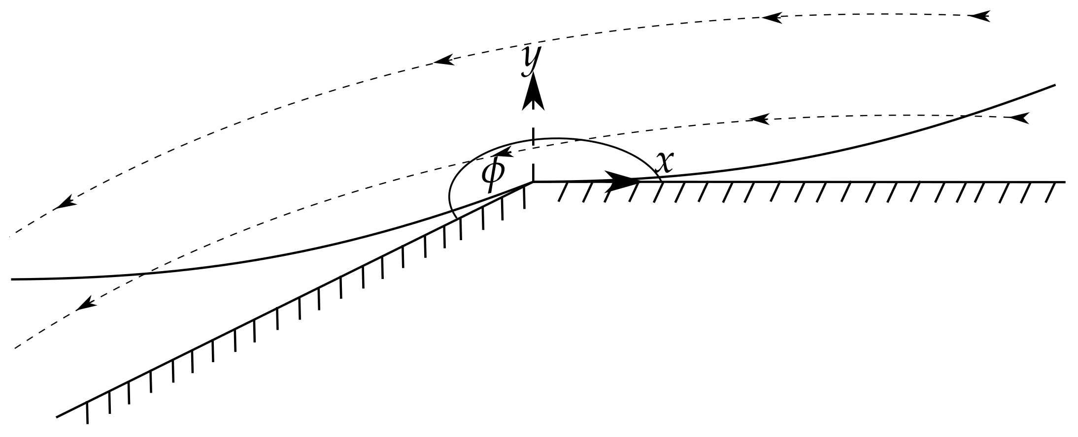
Figure 1. Schematic of the re-entrant corner problem and the boundary layer structure.
Fluids 06 00241 g001
Figure 2. Solution of the upstream boundary layer with a = 1 and p 0 = 1 for q = n . The results are shown for n = 0.2 , 1 and 2 which are denoted by the solid, dashed, and dotted lines respectively.
Fluids 06 00241 g002
Figure 3. Solution of the scaled upstream boundary layer with a = 1 and p 0 = 1 for q = n . The results, which are scaled by the outer solution, are shown for n = 0.2 , 1 and 2 which are denoted by the solid, dashed and dot-dashed lines, respectively.
Fluids 06 00241 g003aFluids 06 00241 g003b
Table 1. Tabulated values of parameters for the WM model. Fluid A is polyisobutylene solution in decalin solvent  [32]. The parameters for Fluid B are those fitted from a pseudo-Carreau Cross WM model to a low-density polyethylene melt [33]. Fluids C and D are polyethylene and polystyrene melts [34].
Fluidnq
A0.330.56
B0.40.0
C0.290.11
D0.170.064
Publisher’s Note: MDPI stays neutral with regard to jurisdictional claims in published maps and institutional affiliations.