Article

Numerical Analysis for Augmentation of Thermal Performance of Single-Phase Flow in Microchannel Heat Sink of Different Sizes with or without Micro-Inserts

by
Shailesh Ranjan Kumar
1 and
Satyendra Singh
2,*
1
Department of Mechanical Engineering, Motihari College of Engineering, Motihari 845401, Bihar, India
2
Department of Mechanical Engineering, Bipin Tripathi Kumaon Institute of Technology, Dwarahat 263653, Uttarakhand, India
*
Author to whom correspondence should be addressed.
Fluids 2022, 7(5), 149; https://doi.org/10.3390/fluids7050149
Submission received: 26 March 2022 / Revised: 19 April 2022 / Accepted: 22 April 2022 / Published: 24 April 2022
(This article belongs to the Special Issue Recent Advances in Computational Fluid Dynamics)

Abstract

:
With the development of miniaturized and enormous heat density generating novel technologies, the microchannel heat sink is rapidly establishing itself in modern cooling fields. Enhancement of heat transfer performance of microchannels is done by incorporating improved design structure, changing working fluids and flow conditions, using different materials for fabrication, etc. Coupling of two parameters influencing heat transfer performance of microchannels is in a nascent age, and complex coupling of heat transfer influencing parameters of microchannel sinks has not been clearly understood yet. This study provides the thermal-fluid flow features–fluid flow characteristics and heat transfer characteristics- of single-phase flow in microchannel of different sizes with or without microinserts by the use of computational fluid dynamics. The numerical simulation is performed by employing distilled water with thermophysical properties that depends on temperature for the Reynolds number range of 56–2242. The effect of microinserts on characteristics of fluid flow and heat transfer is analyzed. The results of numerical analysis show that heat transfer performance in microchannel with microinserts is enhanced effectively, however resistance in fluid flow is increased simultaneously. The 0.5 mm microchannel with microinserts shows the best performance of heat transfer characteristics with enhancement of 1–9% in the Reynolds number range of 56–2242 with simultaneous maximum increase in pressure drop by 14.5%. It’s overall performance, evaluated by thermal performance factor, is found to be best among all cases of three different channel sizes with and without microinserts. The maximum enhancement of heat transfer is found to be in case of 0.5 mm channel size with microinserts by a factor of 1.09. The maximum pressure drop is increased is found to be by factor of 2.28 in case of 2 mm channel size with microinserts.

1. Introduction

The expeditious development of miniaturized and enormous heat density generating novel professional equipment emphasized the problem of requiring a very-compact heat removal system. The problem of increased heat generation density with reduced characteristic dimensions [1] attracted tremendous attention towards fluid flow in microchannel. With the sharp rise in heat generation density [2,3] and continuous decrease in space available for heat removal systems to micro-meter level [4], the pioneer work of Tuckerman and Pease (1981) [5] to solve the problem of removal of enormous heat generation density laid the foundation of microchannel technology. Thereafter, many active researchers have put their effort towards improvement of thermo-hydraulic performance of microchannel employing different methodology [6].
Microchannel technology has been rapidly recognized for compact and effective removal of highly concentrated heat generation in modern cooling fields. Available space constraint for heat removal resulting in decreasing channel size made it possible to have a high heat transfer rate in lesser space due to increased surface area to volume ratio for such smaller channels. Recently, many researchers have paid their attention towards improvement in the design of structure of microchannels and cooling regions in order to have better heat transfer performance. The recent progress in fluid flow and heat transfer in microchannel by varying various channel shape, cross-section and geometry, working fluids, flow conditions and arrangements, materials of fabrication have been reviewed by Gao et al. (2022) [7]; and Mohammad et al. (2013) [8]. Several researchers have put their efforts towards enhancing thermal–hydrodynamic performance of microchannel by employing different techniques of varying-channel shape (wavy [9], tapered [10]); geometry (circular [11], rectangular [12], triangular [13], square [14]); working fluids (water [15], air [16], nano-fluids [17]); materials (silicon [18], copper [19]); and surface modifications (staggered [20], porous [21],, ribs [22], sinusoidal wavy [23]). Hasan et.al (2009) [24] numerically studied the influence of geometry of channel of thermal–hydraulic performance of microchannel. They found that parameters such as relative size of channel, Reynolds number, temperature dependent thermophysical properties influenced microchannel performance. Brandner et al. (2006) [25] investigated heat transfer performance of a crossflow microstructure heat exchanger. He found that heat transfer performance can be intensified with micro column heat exchangers, which were most effective in regimes of transition flow as well as turbulent flow.
Various researchers reported that the main challenge of the study was to manage the pressure drop. The flow loss was reported to get larger with increased complexity in structure, cross-section, or modified flow arrangements. Presently, studies mostly focused on exploring only individual factors, such as channel geometry, cross-section, structure, working fluids, materials, etc., influencing liquid flow characteristics and heat transfer performance. Ma et al. (2022) [26] reported that study of compound effects of variation in structures and cross-section is in a nascent age and needs further exploration in order to have more insight of it. Only a few researchers have worked upon the improvement of the performance of microchannel results because of combing two factors [27,28,29]. Due to unclear insight of the effect of multi-factors on heat transfer performance, there are contradictory results reported by various researchers. Chen et al. (2009) [30], and Wang et al. (2016) [31] reported that triangular microchannel was most efficient for overall performance followed by trapezoidal and rectangular microchannel, contrary to Gunnasegaran et al. (2010) [32], who reported rectangular microchannel to be most efficient for heat transfer performance. The insight of compound effect of multi-factors influencing the performance of microchannel is still unclear and needs more exploration. It will clarify the compound influencing mechanism driven by multi-factors effectively in order to move forward for effective design development of microchannels.
It is found that as the complexity of the cross-section as well as in the arrangement of the flow increases, the effect on heat transfer is accompanied by other simultaneous compound effects of loss of flow or increment of pump work. From previous work, it can be summarize that, though many researchers have paid attention towards enhancement of heat transfer performance, it is essential to carry out more exploration towards the compound effect of changing size and structure on the performance of microchannel. In the present study, the attention is focused on analyzing thermal-fluid flow features such as fluid flow characteristics and heat transfer characteristics of single phase fluid flow through channels of three different channel sizes of 0.5 mm, 1 mm, and 2 mm. Additionally, the effect of insertion of the microinserts on fluid flow characteristics and heat transfer characteristics have been analyzed and discussed. The comparative study of compounding effect of varying channel sizes and addition of microinserts has been performed and presented.
The present study characterizes the thermal–hydraulic performance of a microchannel influenced by different parameters. The pressure drop, heat transfer characteristics and overall thermal–hydrodynamic performance are chosen as cooling performance criteria. The testing parameter considered includes channel size and addition of microinserts. The effect of varying channel size and adding micro inserts on the thermal-hydraulic performance are investigated in this study.

2. Problem Statement and Numerical Methods

2.1. Governing Equations and Boundary Conditions

In the present study, thermal-fluid flow features of fluid flow characteristics and heat transfer characteristics of single-phase fluid flow in microchannels of three different channel sizes of 0.5 mm, 1 mm and 2 mm, with or without microinserts, were investigated by the use of computational fluid dynamics.
The working fluid used in this study is water. The choice of water as working fluid for the present study is valid and justifiable because the characteristic dimension of microchannel under study exceeds the value of 0.1 μm, and hence the flow of water through microchannel was continuum [33]. As the flow of fluid under consideration is continuum and, hence, in the present numerical study, the theory of conventional fluid flow is applicable [34].
To simplify simulation of the heat flow the reasonable assumptions are embedded in the present study. These assumptions are as follows: (1) fluid is Newtonian and incompressible; (2) the steady-state fluid flow is single-phase flow; (3) thermo-physical properties of solid is constant; piecewise-linear variation of thermos-physical properties of fluid with temperature (temperature dependent viscosity of the fluid) is assumed [35]; (4) steady-state heat transfer is considered; (5) the thermal radiation effects are neglected; and (6) viscous dissipation, gravity forces, volume forces and other body forces are assumed to be negligibly small and hence neglected.
By incorporating above assumptions the obtained continuity equation, momentum equation, and energy equation for the region of fluid domain are as follows:
. ( ρ U ) = 0
U = 0
. ( ρ U . U ) = p + . ( μ U )
ρ ( U . U ) = p + . ( μ U )
. ρ c p U T = . k f T
ρ c p ( U . T ) = k f 2 T
where subscript f represents fluid, U is velocity vector of the fluid in the unit of m/s, T is the temperature in unit of K, p is the pressure in unit of Pa, ρ is the density of fluid in unit of kg/m3, μ is the dynamic viscosity of fluid in unit of Pa-s, cp is the specific heat of water in unit of J/kg-K, and kf is the thermal conductivity of fluid in unit of J/s-m-K.
Since, for the solid regions, the velocity vector U = 0, therefore, only the energy equation needs to be considered, which is expressed as
k s 2 T = 0
where subscript s represents solid, and ks is the solid thermal conductivity.
In the present numerical study, the boundary conditions applied are: at the inlet to the microchannel, uniform velocity is applied with inlet temperature of Ti = 303 K; and at the outlet of the microchannel, the relative pressure is assumed to be zero with adoption of average static pressure boundary condition.
In the present model, three domains—solid domain, fluid domain and additional solid domain for microinserts were considered. The coupled heat transfer model was applied. On the interface between fluid and solid domain, the fluid–solid domain interface boundary conditions were employed. The symmetry surfaces were set for both side walls of the microchannel. The contact surfaces between solid–liquid interfaces were set as coupling faces. All the remaining wall surfaces were assigned to adiabatic and no-slip boundary conditions.

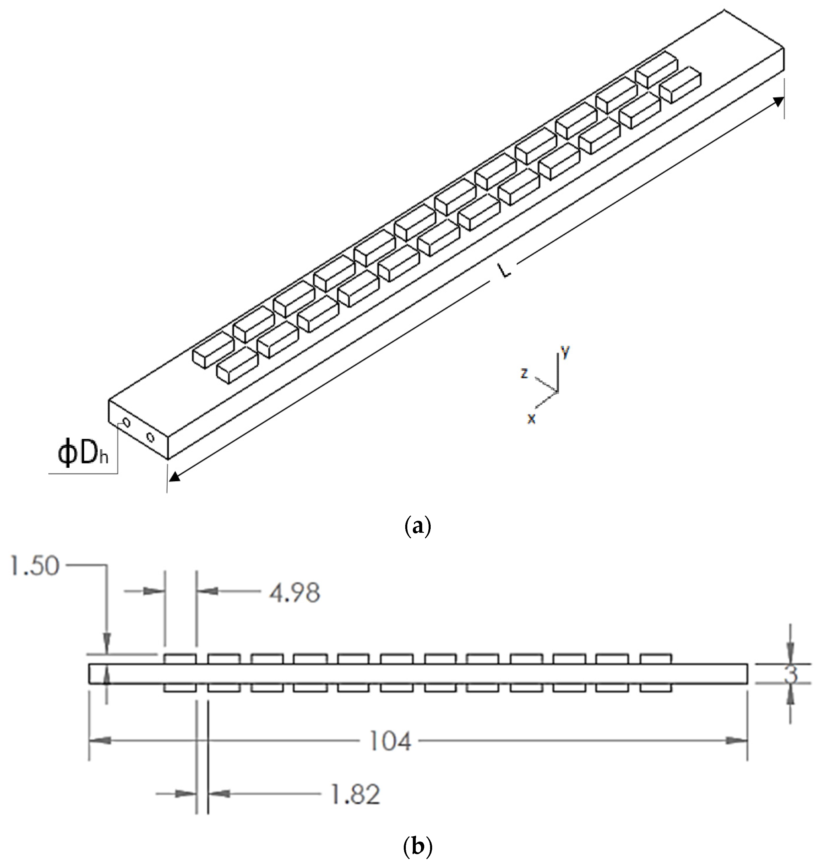
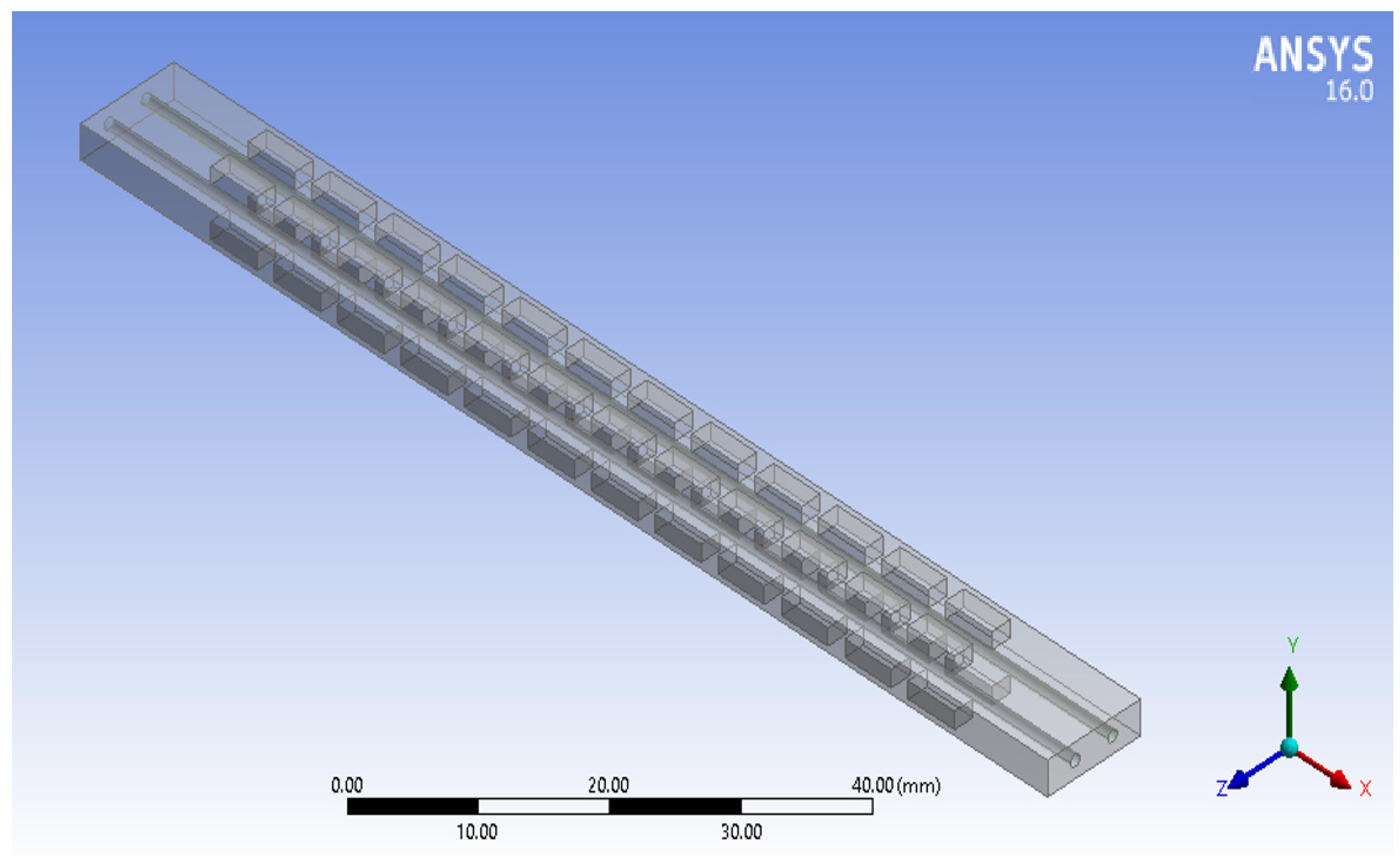
2.2. Physical Models

The schematic diagram of the modelled microchannel heat sink and its dimensions are presented in Figure 1a,b. Dh and L represents the hydraulic diameter of channel and length of the microchannel heat sink, respectively. Considering the microchannel heat sink model as shown in Figure 2, the computational domain model for numerical simulation is presented in Figure 3. The boundary conditions were applied on the computational domain during numerical analysis followed by the processes of meshing. Irrespective of running time during analysis it is evident that higher mesh counts results in high accurate results.

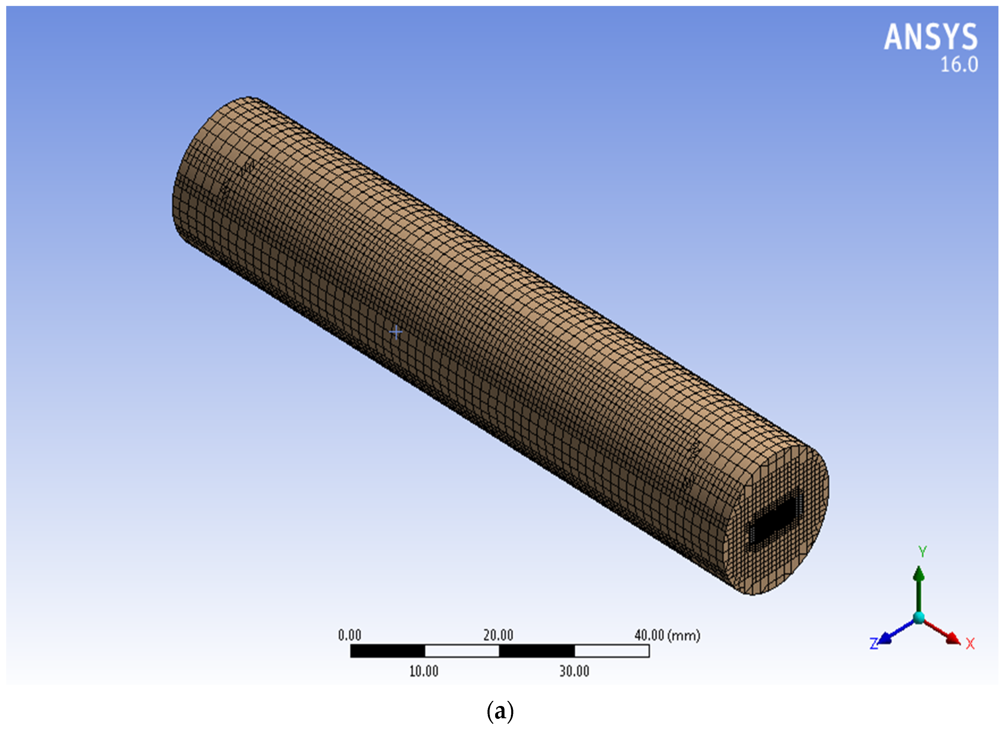
2.3. Computational Fluid Dynamics (CFD) Simulation and Grid Independence Test

In the present study, the computational fluid dynamics (CFD) software ANSYS simulation tool was employed to obtain the numerical solutions. For the computational fluid dynamics model, a grid independence test was conducted for the optimal grid in order to reduce the error introduced because of coarseness of grids. The typical grid on the x-y plane for the microchannel heat sink is shown in Figure 3. Table 1 presents the details of meshing parameters and properties. The cut cell method is employed for grid independent test as the tetrahedral grids are generated for higher quality accuracy for simulation. In the present study, four different grid numbers counted as 756456, 929682, 1043276 and 1145665 were used in grid independent test.
Results of grid independent test shows that variation in numerical solution obtained on two different mesh is insignificant. Solution is varying by increasing number of nodes and element counts as presented in Table 2. The term ∆T is defined as follows: ∆T = temperature difference between cold fluid outlet and inlet; (∆T)n = temperature difference in first element; (∆T)n+1 = temperature difference after first element. The increase in node counts is 2012 when mesh size is increased from 1,229,781 to 1,231,793 with the variation in obtained solution is 0.016% that is insignificant. It can be concluded that by increasing the grid size with increased computational time as well as computational cost, the gain in accuracy of solution is not significant. It can be observed from Table 2 that difference between results corresponding to mesh size of 1,043,276 and 1,145,665 is not noticeable, hence, the node size of 1,229,781 and mesh element count 1,043,276 are selected for numerical simulation.

2.4. Data Reduction

In order to evaluate the performance of the microchannel, different analysis parameters that defines the thermo-hydraulic characteristics of microchannel have been presented with relevant expressions. Additionally, evaluation criteria to estimate overall performance has been described [36].
The Reynolds number (Re) are defined as:
R e = ρ U D h μ
where ρ represents density with the unit of kg/m3, U represents velocity with unit of m/s and μ is the dynamic viscosity of the fluid with unit of Pa-s. Dh represents hydraulic diameter at the microchannel inlet and is defined as
D h = 2 WH W + H
With W as the width of the microchannel in mm and H as height of the microchannel in mm.
The expression for friction factor f of microchannel is as follows:
f = D h 0.5 ρ m U 2 Δ P L
where ρm is the measured density of fluid at temperature of the arithmetic mean of inlet temperature and outlet temperature in kg/m3. L is length of the microchannel in mm. With pin and pout are the pressure at inlet and outlet of the microchannel, respectively, and ∆p is the pressure drop that occurs between inlet and outlet of microchannel and expressed as
Δ p = p in p o u t
The average Nusselt number Nu is expressed as
N u = D h k f , m m C p T b , o u t T b , i n A s T w T b
where kfm is measured thermal conductivity of fluid at arithmetic mean of inlet temperature and outlet temperature in W/m-K. As is contact surface area of the fluid and microchannel in mm2 and is expressed as
As = (W + 2H) L
To evaluate the overall performance of the microchannel for assessing the improved performance an effective parameter, thermal performance factor (TPF) has been adopted. Thermal performance factor of microchannel is defined as the ratio between the heat transfer coefficient with improved heat transfer surfaces and the heat transfer coefficient with plain microchannel at an equal pumping power [37]. Therefore, for a constant pump power, the TPF is expressed as
TPF = h h s P P = N u N u S P P = N u / N u s f / f s 1 3

2.5. Validation of Numerical Model

Before proceeding further to numerical analysis, it becomes necessary to examine and verify the reliability of the proposed model. In order to validate the proposed model reliability, results obtained from simulation were compared with the published results as illustrated in Figure 4. For the comparison, Reynolds number data and Nusselt number data are obtained from published article of the experimental work performed [38,39,40]. It was found that the simulation results agreed and consistent with the reference data. It is also observed that Nusselt number follow the similar trend. This examination indicates good reliability of the present proposed model.

3. Results and Discussion

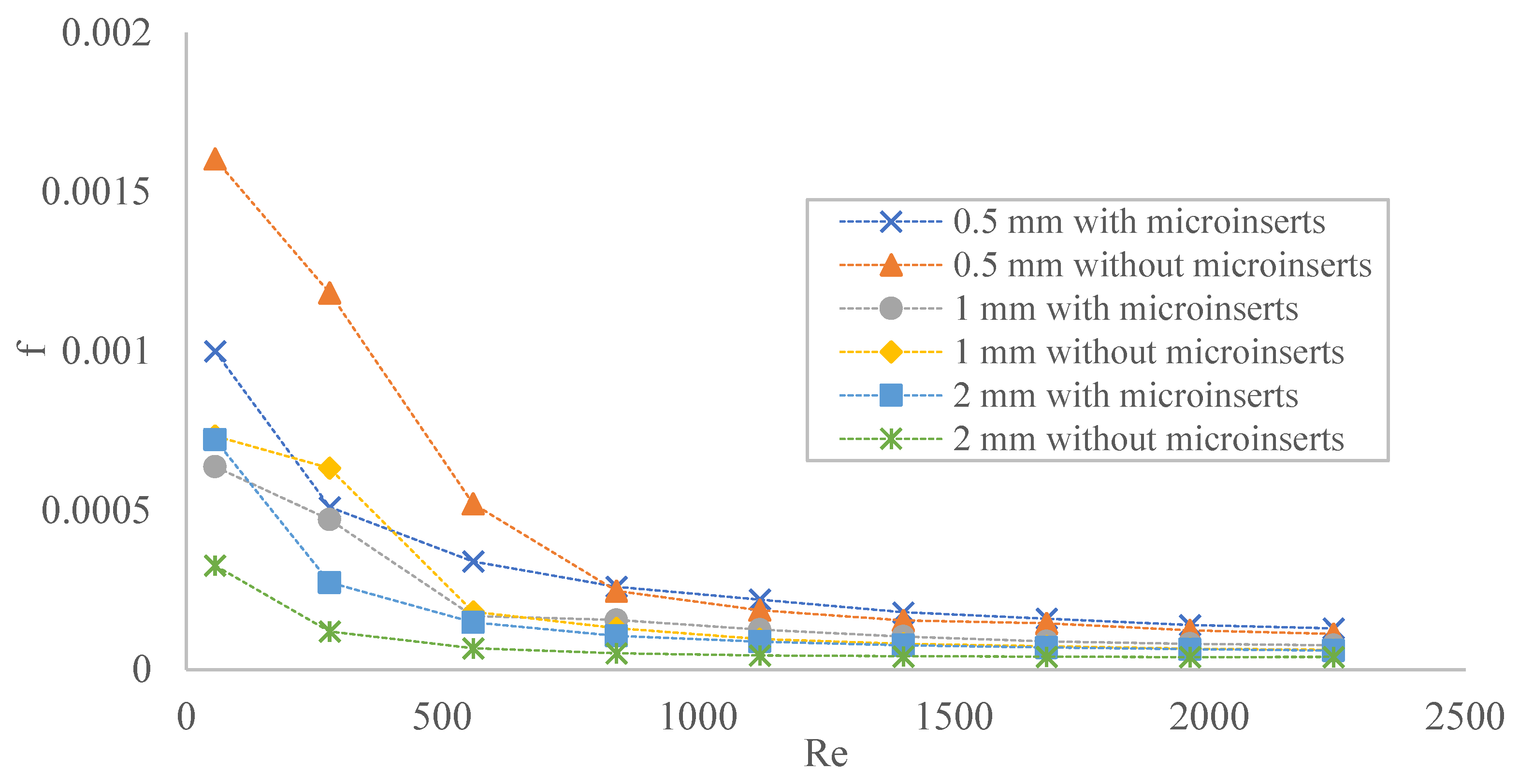
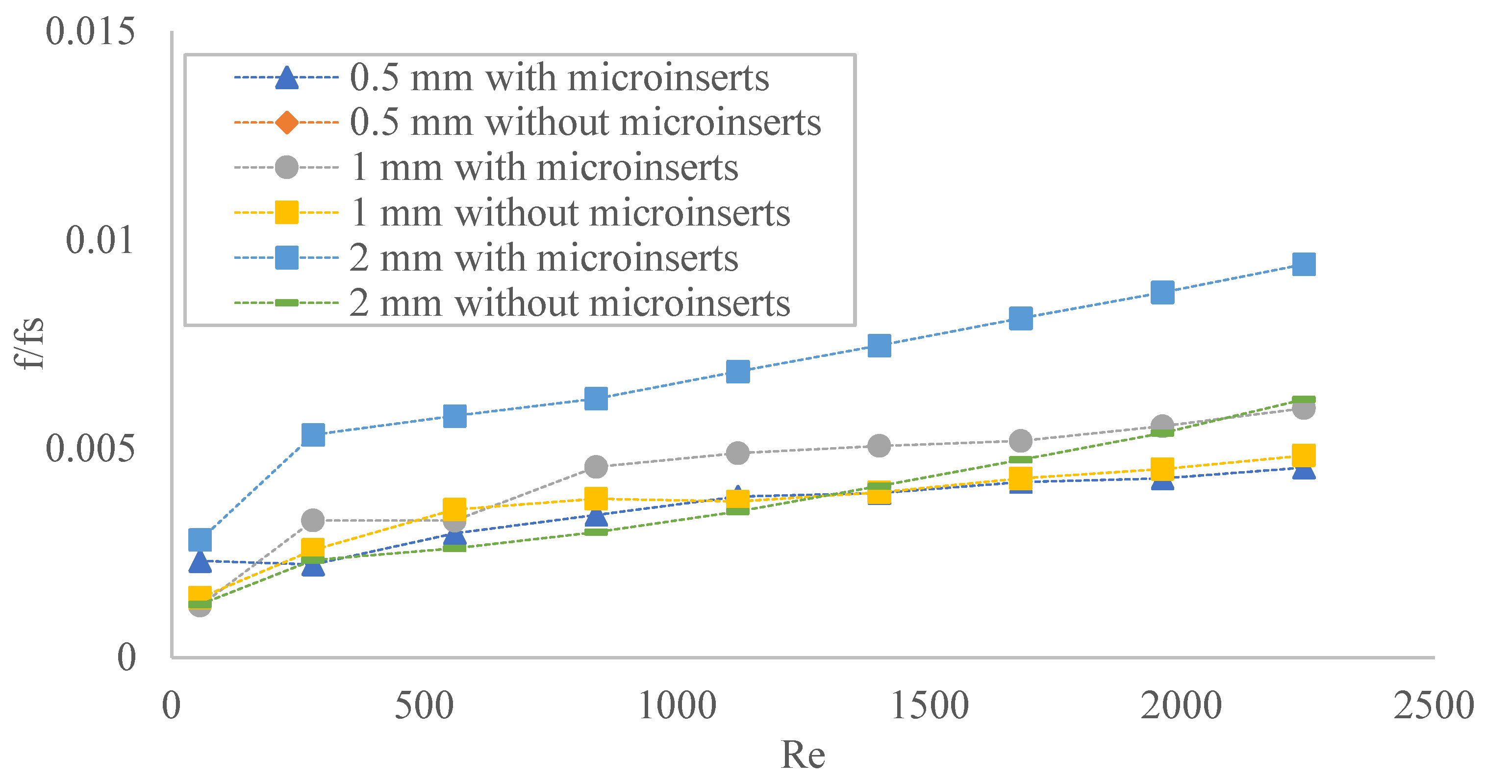
3.1. Pressure Drop Characteristics

In the present study, the working fluid is assumed to be viscous. When viscous fluid passes through a channel, it offers resistance to flow due to viscosity of the fluid, which results in a decrease in pressure drop. Velocity contour and temperature contour for the channel size of 2 mm are shown in Figure 5. The velocity contour of three dimensional (3D) streamline velocity is for the whole domain with equally spaced sampling considering forward direction starting from cold fluid inlet. The variation of evaluated pressure drop with Reynolds number is presented in Figure 6. It is found that addition of microinserts induces the pressure drop increment by the factor in the range of 0.48–1.14, 0.53–1.31 and 1.52–2.28 for the channel size of 0.5 mm, 1 mm, and 2 mm, respectively. It is observed that the pressure drop increases with increasing Reynolds number for all channel size and with microinserts. The variation of pressure drop with increasing Reynolds number is almost linear. With decreasing channel size, for moderate range of Reynolds number, it was found to have maximum pressure drop for smaller size channel and with microinserts. At lower Reynolds number the addition of microinserts resulted in decrement in pressure drop. At lower values of the Reynolds number, the pressure drop is lower due to reason that the higher temperature of water decrease the viscosity of water. By the addition of microinserts to the microchannel, which leads to increase complexities in structure, the flow loss, in terms of pressure drop, is found to become larger. Additionally, decreasing the channel size results in increment in pressure drop with maximum value of pressure drop is found to be in case of 0.5 mm channel size. The compound effect of addition of microinserts and decreasing the channel size simultaneously, leads to have larger pressure drop. The pressure drop in case of smallest channel size of 0.5 mm with microinserts is found to have the largest pressure drop. During designing of the heat exchange systems, a very high Reynolds number usually results in an unacceptably high pressure drop that needs to be avoided. These pressure drops are associated with increased energy cost and compromise the overall effectiveness of heat exchange systems. The rate increase of pressure drop is higher through small size channel with or without microinserts. With increasing channel size, the rate of increasing pressure drop becomes slower. At the low Reynolds number, the addition of microinserts is advantageous, as it exhibits a relatively low pressure drop. Figure 7 depicts variation of friction factor with Reynolds number. Better heat transfer performing systems should have the least possible values of friction factor. It is observed from Figure 7 that values of friction factor decrease as Reynolds number increases. The friction factor for smaller channel size is found to decrease more rapidly with increasing Reynolds number in the range of Reynolds number 56–841. The largest value of friction factor is found to be in case of channel size of 0.5 mm. The largest reduction in the value of friction factor is found to be by 57% due to addition of microinserts in case of 0.5 mm channel size. It may be attributed to a sharp increment of pressure drop due to the reduction of channel size in addition to the presence of microinserts. Friction factor is found to change by the factor in the range of 0.43–1.18, 0.74–1.31 and 1.51–2.27 for the channel size of 0.5 mm, 1 mm, and 2 mm, respectively, when microinserts are added to the microchannel. Narrow passages for fluid flow in smaller channel size offers the highest resistance to fluid flow, which causes a larger pressure drop and, hence, greater pumping power requirements. It is found that addition of microinserts significantly influence the frictional resistance in microchannels with microinserts.

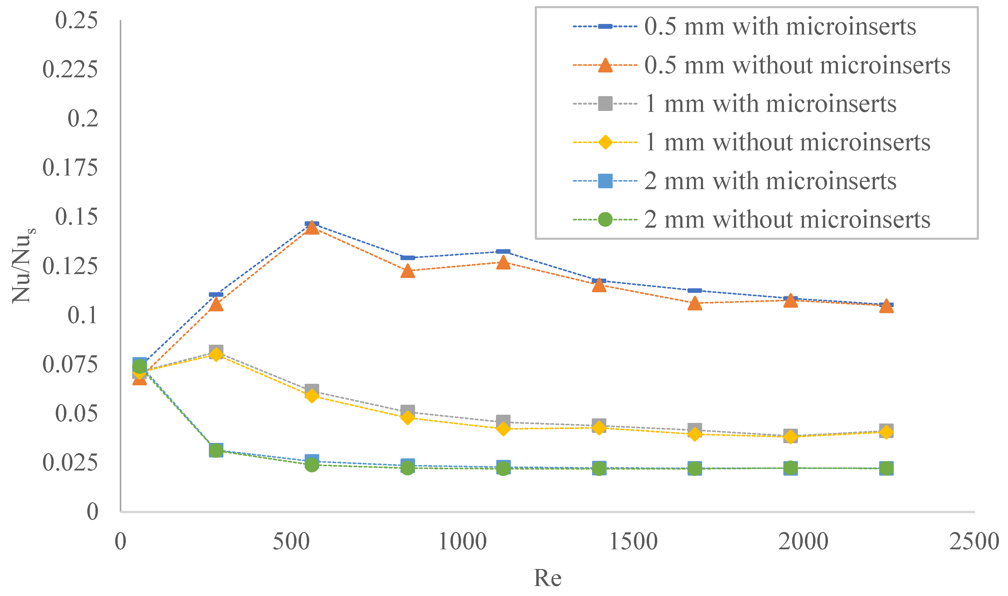
3.2. Heat Transfer Characteristics

Figure 8 illustrates the Nusselt number behavior of microchannel with the Reynolds number for three different channel sizes of 0.5 mm, 1 mm and 2 mm, with or without microinserts. The Nusselt number evaluates the heat transfer performance of the microchannel. It is a measure of ratio of total heat transfer to the conductive heat transfer at the boundary in fluid flow. The Nusselt number varies in the range of 0.84–22.83 and 0.77–22.71 in 0.5 mm channel size with and without microinserts, respectively, for the range of Reynolds number from 56 to 2242. The improvement in heat transfer performance is increased by the factor of 1.01–1.09, 1.01–1.07 and 0.99–1.08 in the case of 0.5 mm, 1 mm and 2 mm, respectively, when microinserts are added to the microchannel. From Figure 8, it is observed that Nusselt number increases with increasing Reynolds number for all cases, which is as expected. The increase of 5%, 3% and 6% in the Nusselt number are found for microchannels with microinserts of channel sizes of 0.5 mm, 1 mm and 2 mm, respectively, as compared with microchannels without microinserts at the Reynolds number of 280. Similarly, the Nusselt number increases of 6%, 7% and 7% are obtained at Reynolds number 841. The value of Nusselt number of microchannels with microinserts is larger than that of without microinserts, which shows the enhancement of heat transfer performance because of addition of microinserts. Decreasing channel size increases Nusselt number. The slope of increment of Nusselt number with increasing Reynolds number is steeper in small channel size, whereas it becomes a flatter slope as channel size increases. This indicates that the smaller channel size can significantly enhance the heat transfer performance. This enhancement of heat transfer characteristics can be attributed to increased convective area and enhanced disturbances of flow. It is found that the microinserts have a less pronounced effect on heat transfer enhancement at two extremities of values of Reynolds number. At a moderate range of Reynolds number for each case, microinserts have significant improvement in the performance of heat transfer characteristics. At a very high value of Reynolds number, effective heat transfer gets hampered as opposite to that of at moderate Reynolds number. Heat transfer performance is intensified by the addition of microinserts to the microchannel. Microinserts are found to be most effective for the smallest channel size of 0.5 mm in the range of Reynolds number of 560–2242, for which Nusselt number is found to be increased in the range of 10.48–22.83. As can be seen from Figure 8, as the Reynolds number increases, the Nusselt number increases sharply at first and then increases slowly. It dictates that the transfer of heat between channel wall and fluid is taking place at a faster rate first and then slows down. This indicates that as the Reynolds number increases, firstly, a quick reduction of temperature difference between channel wall and the fluid takes place, and then reduction slows down. The addition of microinserts causes more uniform temperature gradients in fluid flow fields by disarrange of thermal boundary layer, and is thus beneficial to enhancement of heat transfer. Thereby, addition of microinserts to microchannel improve effective exchange of thermal energy. Between Reynolds number, 56 and 280, heat transfer performance of 2 mm with microinserts are the best one, followed by 1 mm and 0.5 mm channel size. For the Reynolds number above 280 and less than 1961, heat transfer performance of 0.5 mm with microinserts is the best, followed by 1 mm and 2 mm channel size. Above Reynolds number 1961, heat transfer performance of 0.5 mm with microinserts is the best, followed by 2 mm and 1 mm channel size. The enhanced performance of heat transfer characteristics is associated with the larger pressure drop as similar to findings reported by Shen et al. (2018) [20], Feng et al. (2017) [34], and Kumar and Singh (2021) [36].

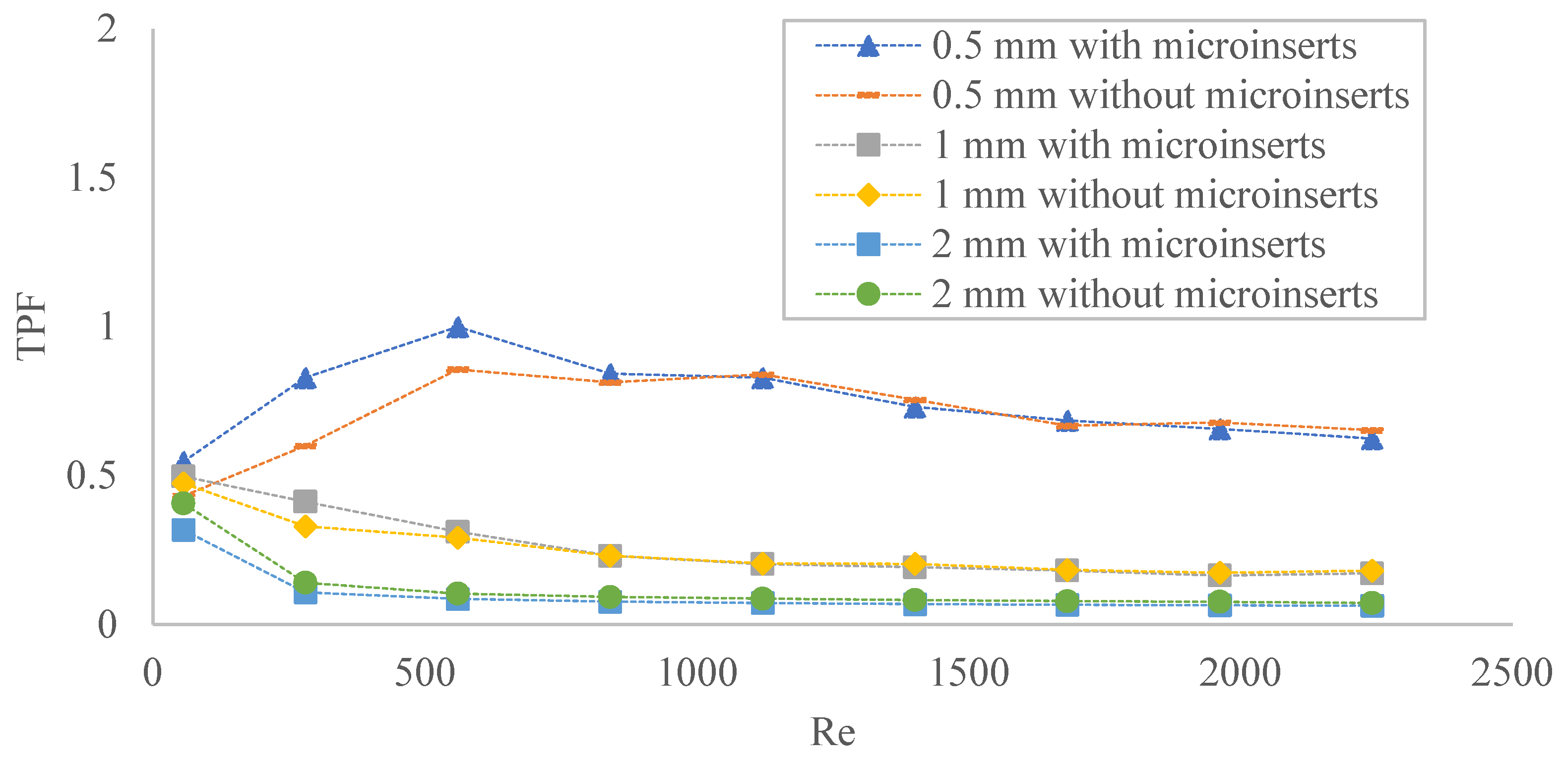
3.3. Thermal Performance Factor

It is interesting to note that addition of microinserts not only enhances the heat transfer performance of microchannel of all sizes, but also causes a high pressure drop by increasing the resistance to fluid flow. Hence, it is necessary to determine the simultaneous effects of heat transfer performance and fluid flow resistance by assessing overall performance of the microchannel for different channel size with the addition of microinserts. The assessment of overall thermal- and hydraulic- performance the method of thermal performance factor (TPF) is employed. Thermal performance factor (TPF) is a ratio of improvement in heat transfer rate to friction factor increment. The value of TPF indicates the extent of enhancement of heat transfer performance to the pressure drop.
The variation of f/fs as a function of Reynolds number is shown in Figure 9. Here, fs is the friction factor that is evaluated by using the Darcy Friction factor equation. It is found that for higher values of Reynolds number, larger channel size values of f/fs increase as Reynolds number increases. For smaller Reynolds number, smaller channel size f/fs behaves differently, as it first sharply increases, followed by a sharp decrease and then very slow increment as the Reynolds number increases. For moderate values of Reynolds number, the addition of microinserts causes a larger increment in f/fs for all channel sizes. However, at a lower Reynolds number, smaller size channel addition of microinserts causes a steep increase of f/fs firstly. This behavior is observed because of the influence of temperature on viscosity of fluid flow.
The variation of Nu/Nus as a function of Reynolds number is shown in Figure 10. Here, Nus is a Nusselt number that is evaluated by using the Dittus–Bolter equation. From Figure 10, it is observed that values of Nu/Nus are continuously decreasing with increasing Reynolds number for larger channel size with sudden decrement at lower Reynolds number and slow decrease at moderate Reynolds number. For moderate range of Reynolds number, the smaller channel size behaves in a similar fashion to that of large channel size. However, at low Reynolds number, Nu/Nus first increases sharply followed by continuous slow decrement. As the channel size keeps decreasing, it is found that, at a low Reynolds number, increment of Nu/Nus is much steeper. The addition of microinserts influences heat transfer to have in easy way for all channel sizes. Additionally, microinserts become more significant as the channel size decreases because it eases the heat transfer rate. This behavior is observed because temperature dependent thermo-physical properties have more influence on the performance of heat transfer characteristics for small size channel. Feng et al. (2017) [34] have also reported that heat transfer enhancement is highly influenced at high Reynolds number due to addition of inserts. They summarized that the temperature dependent properties play a vital role for such observations.
In many engineering applications such as MEMS, etc., microchannel heat sink with less flow resistance characteristics and highly effective heat removal performance is highly desirable. The variation of thermal performance factor with Reynolds number for different size microchannel with microinserts is illustrated in Figure 11. It reveals that TPF holds a decreasing trend if the Reynolds number increases for 1 mm and 2 mm channel size. At the smaller Reynolds number, TPF decreases at a higher rate for large channel size, and at higher Reynolds number, the TPF decrement rate gets flatter. Such a trend is obtained because the rate of pressure drop is dominating over heat transfer rate at low Reynolds number. Dominancy of rate of pressure drop vanishes as the Reynolds number increases and both effects becomes comparable, still, TPF continues to decrease, however. The values of TPF are found to be in the range of 0.96–1.38, 0.95–1.25 and 0.77–0.87 for the channel size of 0.5 mm, 1 mm and 2 mm, respectively. It can be seen that TPF of 0.5 mm channel with and without microinserts first increases and then decreases when Reynolds number increases, while that of 1 mm and 2 mm channel size keeps decreasing. It is worth noting that for the smaller channel size of 0.5 mm, TPF first shows improvement with an increasing Reynolds number followed by a change of trend of TPF to get decreases with the Reynolds number. It may be because, at a lower Reynolds number for smaller channel sizes, heat transfer phenomena are dominant over pressure loss and continue to follow the same trend and, thereafter, suddenly, dominant effects become reversed. It is observed in Figure 11 that TPF values are essentially lower for all channel size with microinserts than that of channel without microinserts for higher Reynolds number. For decreasing channel size TPF values of channel with microinserts are dominating over that of channel without microinserts. Decreasing channel size influences enhancement in heat transfer rate more effectively at lower Reynolds number. It can be concluded that combined effect of decrement of channel size and addition of microinserts improves the overall performance of microchannel at lower values of Reynolds number. Addition of microinserts are beneficial for lower Reynolds numbers when the channel size decreases, however, it can be of a reverse effect for large channel sizes. Overall, for smaller channel sizes, heat transfer performance is more effective at lower values of Reynolds number, on the other hand, flow resistance increment is more dominant at higher Reynolds numbers.

4. Conclusions

The numerical simulation using ANSYS is performed for three different channel sizes of 0.5 µm, 1 µm and 2 µm with and without microinserts. For numerical simulation, water with temperature dependent thermo-physical properties was employed as a working fluid. The major conclusions drawn from the present study are as follows:
  • The fluid flow behavior of microchannels is significantly affected by the presence of microinserts. The pressure drop was increased due to the presence of microinserts. The pressure drop of fluid flow through all sized channels with microinserts was large when compared to channels without microinserts. Additionally, the friction factors were decreasing with an increase in Reynolds number for all channel sizes. Decreasing channel size of microchannels resulted in an increase in the pressure drop in the microchannel. The addition of microinserts causes increment in the pressure drop with an increment factor of 0.48–1.14, 0.53–1.31 and 1.52–2.28 for the channel size of 0.5 mm, 1 mm, and 2 mm, respectively. The maximum pressure drop is increased and is found to be by a factor of 2.28 in the case of a 2 mm channel size with microinserts.
  • Addition of microinserts to the microchannel enhanced the heat transfer with simultaneous increase in the flow resistance. The small channel size combined with microinserts significantly improved the heat transfer, resulting in lower temperature heating surface. The largest enhancement in Nusselt number due to inserts were observed to be in 0.5 µm channel size, especially, at lower Reynolds number.
  • Assessment of the overall performance channels were evaluated by using the performance evaluation criteria—thermal performance factor, which is a ratio of increase in heat transfer against increment in friction factor. It was found that the additions of microinserts are beneficial to the overall performance of all channel sizes. The 0.5 µm channel size can provide significantly improved performance, followed by that of 1 µm channel size, however, 2 µm channel size had the least improved performance due to the addition of microinserts.
The obtained results show that microinserts not only increase the performance in heat transfer characteristics, but also cause more resistance to the fluid flow, resulting in increased pressure drop. Appreciable augmentation of heat transfer is observed, and the analysis indicated that addition of microinserts exhibited improved overall performance. Additionally, the overall performance is found to improve when the channel size is decreasing.

Author Contributions

S.R.K.: Conceptualization, methodology, software analysis, validation, investigation, writing—original draft preparation. S.S.: visualization, supervision, writing-review and editing project administration. All authors have read and agreed to the published version of the manuscript.

Funding

This research received no external funding.

Conflicts of Interest

The authors declare no conflict of interest.

Nomenclature

SymbolsDescriptionsUnit
AsContact surface area of the fluid and microchannelmm2
CFDComputational fluid dynamics
cpSpecific heat of waterJ/kg-K
DhHydraulic diametermm
fFriction factor
HHeight of the microchannelmm
hHeat transfer coefficientW/m2-K
kfThermal conductivity of fluidJ/s-m-K
KsSolid thermal conductivityJ/s-m-K
LLength of the microchannelmm
mMasskg
NuNusselt number
pPressurePa
ReReynolds Number
TTemperatureK
TPFThermal performance factor
UFluid velocitym/s
WWidth of the microchannelmm
ΔpPressure difference
ΔTTemperature difference
Greek symbols
ρFluid densityKg/m3
µDynamic viscosityPa-s
Subscript
fFluid
sSolid

References

  1. Pan, X.; Hong, X.; Xu, L.; Li, Y.; Yan, M.; Mai, L. On-chip micro/nano devices for energy conversion and storage. Nano Today 2019, 28, 100764. [Google Scholar] [CrossRef]
  2. Abdoli, A.; Jimenez, G.; Dulikravich, G.S. Thermo-fluid analysis of micro pin-fin array cooling configurations for high heat fluxes with a hot spot. Int. J. Therm. Sci. 2015, 90, 290–297. [Google Scholar] [CrossRef]
  3. Sohel, M.; Nieto-de-Castro, C.A. A critical review of traditional and emerging techniques and fluids for electronics cooling. Renew. Sustain. Energy Rev. 2017, 78, 821–833. [Google Scholar] [CrossRef]
  4. Dixit, T.; Ghosh, I. Review of micro- and mini-channel heat sinks and heat exchangers for single phase fluids. Renew. Sustain. Energy Rev. 2015, 41, 1298–1311. [Google Scholar] [CrossRef]
  5. Tuckerman, D.B.; Pease, R.F.W. High-Performance Heat Sinking for VLSI. IEEE Electron Device Lett. 1981, 2, 126–129. [Google Scholar] [CrossRef]
  6. Alihosseini, Y.; Zabetian, M.; Mohammad, T.; Heyhat, M. Thermo-hydraulic performance of wavy microchannel heat sink with oblique grooved finned. Appl. Therm. Eng. 2021, 189, 116719. [Google Scholar] [CrossRef]
  7. Gao, J.; Hu, Z.; Yang, Q.; Liang, X.; Wua, H. Fluid flow and heat transfer in microchannel heat sinks: Modelling review and recent progress. Therm. Sci. Eng. Prog. 2022, 29, 101203. [Google Scholar] [CrossRef]
  8. Mohammed, A.; Mohd-Ghazali, N.; Ahmad, R. Thermal and hydrodynamic analysis of microchannel heat sinks: A review. Renew. Sustain. Energy Rev. 2013, 21, 614–622. [Google Scholar] [CrossRef]
  9. Xie, G.; Liu, J.; Liu, Y.; Sunden, B.; Zhang, W. Comparative study of thermal performance of longitudinal and transversal-wavy microchannel heat sinks for electronic cooling. J. Electron. Packag. 2013, 135, 21008. [Google Scholar] [CrossRef]
  10. Osanloo, B.; Mohammadi-Ahmar, A.; Solati, A.; Baghani, M. Performance enhancement of the double-layered microchannel heat sink by use of tapered channels. Appl. Therm. Eng. 2016, 102, 1345–1354. [Google Scholar] [CrossRef]
  11. Ali, A.M.; Ron, A.; Kadhim, H.T.; Angelino, M.; Gao, S. Thermo-hydraulic performance of a circular microchannel heat sink using swirl flow and nanofluid. Appl. Therm. Eng. 2021, 191, 116817. [Google Scholar] [CrossRef]
  12. Datta, A.; Sharma, V.; Sanyal, D.; Das, P. A conjugate heat transfer analysis of performance for rectangular microchannel with trapezoidal cavities and ribs. Int. J. Therm. Sci. 2019, 138, 425–446. [Google Scholar] [CrossRef]
  13. Liang, J.; Engelbrecht, K.; Nielsen, K.K.; Loewe, K.; Vieyra, H.; Barcza, A.; Bahl, C.R.H. Performance assessment of a triangular microchannel active magnetic regenerator. Appl. Therm. Eng. 2021, 186, 116519. [Google Scholar] [CrossRef]
  14. Khalesi, J.; Sarunac, N. Numerical analysis of flow and conjugate heat transfer for supercritical CO2 and liquid sodium in square Microchannels. Int. J. Heat Mass Transf. 2019, 132, 1187–1199. [Google Scholar] [CrossRef]
  15. Burk, B.E.; Grumstrup, T.P.; Bevis, T.A.; Kotovsky, J.; Bandhauer, T.M. Computational examination of two-phase microchannel heat transfer correlations with conjugate heat spreading. Int. J. Heat Mass Transfer. 2019, 132, 68–79. [Google Scholar] [CrossRef]
  16. Su, L.; Duan, Z.; He, B.; Ma, H.; Ning, X.; Ding, G.; Cao, Y. Heat transfer characteristics of thermally developing flow in rectangular microchannels with constant wall temperature. Int. J. Therm. Sci. 2020, 155, 106412. [Google Scholar] [CrossRef]
  17. He, W.; Mashayekhi, R.; Toghraie, D.; Akbari, O.A.; Li, Z.; Tlili, I. Hydrothermal performance of nanofluid flow in a sinusoidal double layer microchannel in order to geometric optimization. Int. Commun. Heat Mass Transf. 2020, 117, 104700. [Google Scholar] [CrossRef]
  18. Derakhshanpour, K.; Kamali, R.; Eslami, M. Effect of rib shape and fillet radius on thermal-hydrodynamic performance of microchannel heat sinks: A CFD study. Int. Commun. Heat Mass Transf. 2020, 119, 104928. [Google Scholar] [CrossRef]
  19. Soleimani, A.; Sattari, A.; Hanafizadeh, P. Thermal analysis of a microchannel heat sink cooled by two-phase flow boiling of Al2O3 HFE-7100 nanofluid. Therm. Sci. Eng. Prog. 2020, 20, 100693. [Google Scholar] [CrossRef]
  20. Shen, H.; Zhang, Y.; Wang, C.C.; Xie, G. Comparative study for convective heat transfer of counter-flow wavy double-layer microchannel heat sinks in staggered arrangement. Appl. Therm. Eng. 2018, 137, 228–237. [Google Scholar] [CrossRef]
  21. Dey, P.; Saha, S.K. Fluid flow and heat transfer in microchannel with porous bio-inspired roughness. Int. J. Therm. Sci. 2021, 161, 106729. [Google Scholar] [CrossRef]
  22. Li, X.Y.; Wang, S.L.; Wang, X.-D.; Wang, T.-H. Selected porous-ribs design for performance improvement in double-layered microchannel heat sinks. Int. J. Therm. Sci. 2019, 137, 616–626. [Google Scholar] [CrossRef]
  23. Bin, F.; Hasis, A.; Krishna, P.M.M.; Aravind, G.P.; Deepu, M.; Shine, S.R. Thermo hydraulic performance analysis of twisted sinusoidal wavy Microchannels. Int. J. Therm. Sci. 2018, 128, 124–136. [Google Scholar]
  24. Hasan, M.I.; Rageb, A.A.; Yaghoubi, M.; Homayoni, H. Influence of channel geometry on the performance of a counter flow microchannel heat exchanger. Int. J. Therm. Sci. 2009, 48, 1607–1618. [Google Scholar] [CrossRef]
  25. Brandner, J.J.; Anurjew, E.; Bohn, L.; Hansjosten, E.; Henning, T.; Schygulla, U.; Wenka, A.; Schubert, K. Concepts and realization of microstructure heat exchangers for enhanced heat transfer. Exp. Therm. Fluid Sci. 2006, 30, 801–809. [Google Scholar] [CrossRef]
  26. Ma, Y.; Liu, C.; Jiaqiang EMao, X.; Yu, Z. Research on modeling and parameter sensitivity of flow and heat transfer process in typical rectangular microchannels: From a data-driven perspective. Int. J. Therm. Sci. 2022, 172 Pt B, 107356. [Google Scholar] [CrossRef]
  27. Khoshvaght-Aliabadi, M.; Nozan, F. Water cooled corrugated minichannel heat sink for electronic devices: Effect of corrugation shape. Int. Commun. Heat Mass Trans. 2016, 76, 188–196. [Google Scholar] [CrossRef]
  28. Alfaryjat, A.A.; Mohammed, H.A.; Adam, N.M.; Stanciu, D.; Dobrovicescu, A. Numerical investigation of heat transfer enhancement using various nanofluids in hexagonal microchannel heat sink. Therm. Sci. Eng. Prog. 2018, 5, 252–262. [Google Scholar] [CrossRef]
  29. Ma, H.; Duan, Z.; Ning, X.; Su, L. Numerical investigation on heat transfer behavior of thermally developing flow inside rectangular microchannels. Case Stud. Therm. Eng. 2021, 24, 100856. [Google Scholar] [CrossRef]
  30. Chen, Y.; Zhang, C.; Shi, M.; Wu, J. Three-dimensional numerical simulation of heat and fluid flow in noncircular microchannel heat sinks. Int. Commun. Heat Mass Trans. 2009, 36, 917–920. [Google Scholar] [CrossRef]
  31. Wang, H.; Chen, Z.; Gao, J. Influence of geometric parameters on flow and heat transfer performance of micro-channel heat sinks. Appl. Therm. Eng. 2016, 107, 870–879. [Google Scholar] [CrossRef]
  32. Gunnasegaran, P.; Mohammed, H.A.; Shuaib, N.H.; Saidur, R. The effect of geometrical parameters on heat transfer characteristics of microchannels heat sink with different shapes. Int. Commun. Heat Mass Trans. 2010, 37, 1078–1086. [Google Scholar] [CrossRef]
  33. Koo, J.; Kleinstreuer, C. Liquid flow in microchannels: Experimental observations and computational analyses of microfluidics effects. J. Micromech. Microeng. 2003, 13, 568–579. [Google Scholar] [CrossRef]
  34. Feng, Z.; Luo, X.; Guo, F.; Li, H.; Zhang, J. Numerical investigation on laminar flow and heat transfer in rectangular microchannel heat sink with wire coil inserts. Appl. Therm. Eng. 2017, 116, 597–609. [Google Scholar] [CrossRef]
  35. Chai, L.L.; Xia, G.; Zhou, M.; Li, J.; Qi, J. Optimum thermal design of interrupted microchannel heat sink with rectangular ribs in the transverse microchambers. Appl. Therm. Eng. 2013, 51, 880–889. [Google Scholar] [CrossRef]
  36. Kumar, S.R.; Singh, S. CFD analysis for heat transfer and fluid flow in microchannel heat sink with micro inserts. Mater. Today Proc. 2021, 46 Pt 20, 11213–11216. [Google Scholar] [CrossRef]
  37. Webb, R.L. Performance evaluation criteria for use of enhanced heat transfer surfaces in heat exchanger design. Int. J. Heat Mass Transf. 1981, 24, 715–726. [Google Scholar] [CrossRef]
  38. Ling, W.; Zhou, W.; Yu, W.; Zhou, F.; Chen, J.; Hui, K.S. Experimental investigation on thermal and hydraulic performance of microchannels with interlaced configuration. Energy Convers. Manag. 2018, 174, 439–452. [Google Scholar] [CrossRef]
  39. Wang, G.; Qian, N.; Ding, G. Heat transfer enhancement in microchannel heat sink with bidirectional rib. Int. J. Heat Mass Transf. 2019, 136, 597–609. [Google Scholar] [CrossRef]
  40. Deng, D.; Chen, L.; Chen, X.; Pi, G. Heat transfer and pressure drop of a periodic expanded-constrained microchannels heat sink. Int. J. Heat Mass Transf. 2019, 140, 678–690. [Google Scholar] [CrossRef]
Figure 1. (a) Schematic diagram of microchannel heat sink (b) microchannel dimensions.
Fluids 07 00149 g001
Figure 2. Three-dimensional view of microchannel heat sink model.
Fluids 07 00149 g002
Figure 3. (a,c) Computational grids (b) Computational domain, used for computational fluid dynamics (CFD) simulation.
Fluids 07 00149 g003aFluids 07 00149 g003b
Figure 4. Consistency check for the proposed model.
Fluids 07 00149 g004
Figure 5. (a) Velocity contour starts from cold fluid duct with equally spaced sampling for 2 mm channel size. (b) Temperature contour of 2 mm channel size.
Fluids 07 00149 g005
Figure 6. The pressure drop as a function of Reynolds number.
Fluids 07 00149 g006
Figure 7. Friction factor variation as a function of Reynolds number.
Fluids 07 00149 g007
Figure 8. Variation of Nusselt number as a function of Reynolds number.
Fluids 07 00149 g008
Figure 9. Variation of f/fs with Reynolds number.
Fluids 07 00149 g009
Figure 10. Variation of Nu/Nus with Reynolds number.
Fluids 07 00149 g010
Figure 11. Variation of thermal performance factor with Reynolds number.
Fluids 07 00149 g011
Table 1. Meshing parameters and properties.
Use Advanced Size FunctionOn: Proximity and Curvature
Relevance CenterCoarse
SmoothingMedium
Inflation OptionSmooth Transition
Transition Ratio0.272
Maximum Layers5
Growth Rate1.5
MethodCut Cell
Nodes1,229,781
Elements1,043,276
Table 2. Grid details of grid independence test.
NodeElementTemperature Difference (∆T) Δ T n + 1 Δ T n Δ T n × 100 Pressure Difference (ΔP) Δ P n + 1 Δ P n Δ P n × 100
872,615756,45617.26-1.17-
1,099,007929,68218.979.901.245.98
1,229,7811,043,27619.934.811.304.83
1,231,7931,145,66519.960.151.353.84
Publisher’s Note: MDPI stays neutral with regard to jurisdictional claims in published maps and institutional affiliations.

