Article

Serre-Green-Naghdi Dynamics under the Action of the Jeffreys’ Wind-Wave Interaction

by
Miguel Alberto Manna
1,* and
Anouchah Latifi
2
1
Laboratoire Charles Coulomb-UMR 5221 CNRS, Université de Montpellier, 34095 Montpellier, France
2
Departement of Mechanics, Qom University of Technology, Qom 1519-37195, Iran
*
Author to whom correspondence should be addressed.
Fluids 2022, 7(8), 266; https://doi.org/10.3390/fluids7080266
Submission received: 5 July 2022 / Revised: 20 July 2022 / Accepted: 24 July 2022 / Published: 4 August 2022
(This article belongs to the Special Issue Nonlinear Wave Hydrodynamics, Volume II)

Abstract

:
We derive the anti dissipative Serre-Green-Naghdi (SGN) equations in the context of nonlinear dynamics of surface water waves under wind forcing, in finite depth. The anti-dissipation occurs du to the continuos transfer of wind energy to water surface wave. We find the solitary wave solution of the system, with an increasing amplitude under the wind action. This leads to the blow-up of surface wave in finite time for infinitely large asymptotic space. This dispersive, anti-dissipative and fully nonlinear phenomenon is equivalent to the linear instability at infinite time. The theoretical blow-up time is calculated based on real experimental data. Naturally, the wave breaking takes place before the blow-up time. However, the amplitude’s growth resulting in the blow-up could be observed. Our results show that, based on the particular type of wind-wave tank data used in this paper, for h = 0.14 m , the amplitude growth rate is of order 0.1 which experimentally, is at the measurability limit. But we think that by gradually increasing the wind speed U10, up to 10 m/s, it is possible to have the experimental confirmation of the present theory in existing experimental facilities.

1. Introduction

Euler equations which describe both water and air flow dynamics provide the framework for studying wind-generated surface waves. Airflow and surface waves are in mutual interaction. Indeed, surface waves are generated by the airflow, and the generated surface waves modify the profile of air pressure on the water surface. Wave growth occurs due to the continuous energy and momentum transfer from air to the surface wave, the so-called anti dissipation mechanism. To be more specific, local air pressure oscillations due to surface waves are in quadrature with surface waves’ elevation slope. Therefore, surface waves and air pressure oscillations result in anti-phase which causes momentum transfer from airflow to water surface waves. Consequently, according to water depth and wind speed, the monochromatic waves’ amplitude grows exponentially in time. However, several assumptions and approximations must be carried out in order to describe the problem. The first theoretical work on surface wind-waves interaction was published almost a century ago by Jeffreys (Jeffreys [1,2]). In this approach, Jeffreys disregards the viscosity and linearizes the equations of motion in a two dimensional deep-water model. In this theory, by denoting both wind and water surface waves using normal Fourier modes of wave-number k, the linear wave growth γ J can be computed. As a result, the wave amplitude η ( x , t , k ) , where x and t are spatial and temporal coordinates, respectively, has a time exponential growth of η ( x , t , k ) exp ( γ J t ) . Hence, the wave amplitude evolution depends on the value of the coefficient γ J , which itself depends on wind speed. Recently, this work was extended to finite depth, Manna et al. [3], and it was that in this context, the coefficient γ J depends not only on wind speed, but also on the water depth h.
However, dispersionless and linear approximations are valid within certain limits. Outside the validity of these approximations, dispersive and non-linear processes start to become relevant. Here, we studied the time evolution of a normal mode k, under the simultaneous actions of weak dispersion and anti-dissipation, in a fully nonlinear approach. Nonlinearity tends to counterpoise dispersion as well as thwart time exponential growth or decay due to anti-dissipation or dissipation, respectively. Solitary waves are the result of the balance between dispersion and nonlinearity, as it occurs in the Korteweg-de Vries equation (Korteweg and de Vries [4]), Boussinesq equation (Whitham [5]) or Serre-Green-Naghdi equation (Green et al. [6], Green and Naghdi [7]). If balance occurs between dissipation or anti-dissipation and nonlinearity, this can result in shock structures as in the Burgers equation (Whitham [5]), while competition between dispersion, dissipation and weak non-linearity, is found in the Korteweg-de Vries–Burgers equation (KdV–B). The KdV–B equation arises from many and various physical contexts (see f.i. Benney [8], Johnson [9], Grad and Hu [10], Hu [11], Wadati [12], Karahara [13]).
In recent years, due to their fully nonlinear nature, SGN equations have aroused great interest in the field of fluid dynamics for the following reasons: their potential applications to describe and study surface waves in shallow water (Jalali and Borthwick [14], Le [15]); to develop various methods for solving these equations (Dehghan and Abbaszadeh [16], Sharifian et al. [17]); and to study the mathematical properties of SGN equations (Lannes and Métivier [18]) or their properties or solutions (Tkachenko et al. [19]).
In this work, we derived a Serre-Green-Naghdi type equation with anti-dissipation due to the Jeffreys mechanism, taking into account the simultaneous competing effects of dispersion, anti-dissipation and full nonlinearity.
The paper is organized as follows. In Section 2.2, the fully nonlinear SGN equations, describing the propagation of surface waves in shallow water, are derived. In Section 3, the wind action is taken into account through Jeffreys’ hypothesis. The result is a new two-phase water/airflow system in which the constant atmospheric pressure is replaced by variable pressure, depending on x and t, resulting in a flux of energy from the wind to waves. In Section 2.2, we present and justify the application of Green’s theorem in one dimension to the matrix form of SGN equations and study the soliton solution of the SGN system as well as the associated blow-up in finite time. In Section 3, the blow up time is evaluated on the basis of experimental data. Finally, in Section 4 conclusions and perspectives are drawn. Appendix A, provides a direct proof of the application of Green’s theorem in one dimension to the matrix form of SGN equations.

2. Materials and Methods

2.1. The Water Domain in the Nonlinear Serre-Green-Naghdi Approximation

We associated water particles, in a system of two-dimensional Cartesian coordinates ( x , z ) with origin 0, where z is the upward vertical direction. We let z = 0 at the water–air interface. Hence, the positive values of z, z ] 0 , [ , correspond to the (unperturbed) air domain, while negative values of z, z [ h , 0 ] correspond to the (unperturbed) water domain. Consequently, for the bottom of the water domain of depth h, we obtain z = h . The bottom is considered to be impermeable, and both water and air, are taken to be inviscid and incompressible. Moreover, the surface tension effects, at the interface, are not taken into account. The governing equations are the well known Euler equations, with the mass conservation equations used in ( x , z , t ) frame, where t accounts for the time. Namely,
u x + w z = 0 ,
ρ w ( u t + u u x + w u z ) = P x ,
ρ w ( w t + u w x + w w z ) = P z g ρ w ,
where u ( x , z , t ) and w ( x , z , t ) are the fluid’s horizontal and vertical velocities, respectively. P ( x , z , t ) is the Archimedean pressure, g the gravitational acceleration, ρ w is the water density and subscripts x, z and t denote partial derivatives with respect to x, z and t, respectively. The set of Equations (1) are completed by the following boundary conditions:
w = 0 , at z = h ,
η t + u η x w = 0 , at z = η ,
P = P a , at z = η ,
where P a ( x , z , t ) is the air pressure, and Equation (2c) expresses the pressure’s continuity across the air/water interface. Notice that z = η ( x , t ) is the perturbed water surface. For convenience, we introduced a reduced pressure P , such that P ( x , z , t ) = P ( x , z , t ) + ρ w g z P 0 , where P 0 denotes the atmospheric pressure. Using the reduced pressure P ( x , z , t ) , the set of Equations (1) can be written as follows:
ρ w ( u t + u u x + w u z ) = P x ,
ρ w ( w t + u w x + w w z ) = P z ,
P ( x , η , t ) ρ w g η + P 0 = P a ( x , η , t ) .
Shallow water model equations, such as the Korteweg-Vries, modified Korteweg-Vries, and Boussinesq equations and many others, are usually derived by performing an asymptotic analysis directly from the equations of continuity (1a), the motion Equations (3a) and (3b) and the boundary conditions (2a,b) and (3c) (see Latifi et al. [20] and references therein). In this work, our approach was somewhat different, in the sense that instead of applying a perturbation theory to the entire problem, we first considered the nonlinear evolution of a given velocity field profile. Indeed, we assumed the horizontal velocity u ( x , z , t ) to be independent of z, i.e.,
u = u ( x , t ) .
The choice of Equation (4), is known as the columnar flow hypothesis, which was introduced by Su and Gardner [21], and Serre [22]. Using Equations (1a), (2a) and (4) we obtain
w ( x , z , t ) = ( z + h ) u x ( x , t ) .
Hence, Equations (2b) and (3a),(3b) read
η t + [ u ( η + h ) ] x = 0 ,
ρ w ( u t + u u x ) = P x ,
ρ w ( z + h ) ( u x t + u u x x u x 2 ) = P z .
The integration of Equation (6c), using Equation (3c), yields the pressure P ( x , z , t ) :
P ( x , z , t ) = 1 2 ρ w [ ( z + h ) 2 ( η + h ) 2 ] ( u x t + u u x x u x 2 ) + P a ( x , η , t ) + ρ w g η P 0 .
The next step consists of substituting Equation (7) in Equation (6b), and taking the z-average of Equation (6b) for h z η . Finally, using Equation (3c) we obtained the following system:
η t + [ u ( η + h ) ] x = 0 ,
u t + u u x + g η x 1 3 ( η + h ) { ( η + h ) 3 ( u x t + u u x x u x 2 ) } x = 1 ρ w [ P a ( x , η , t ] x .
If P a = P 0 , Equations (8a) and (8b) are reduced to the usual Serre-Green-Naghdi equations. However, in our approach, P a was not taken as equal to P 0 , and the expression of P a ( x , z , t ) was found using the sheltering mechanism.

2.2. Jeffreys’ Sheltering Mechanism of Wind Waves Generation Applied to Serre-Green-Nagdhi Equations

The physical sheltering mechanism assumes that the energy transfer is caused by pressure drag (also known as “form drag”). The air pressure on the windward face of the wave is larger than the leeward face, which is the origin of continuous energy transfer from wind to wave. Using dimensional arguments, Jeffreys [1,2] showed that the air pressure perturbation P a ( x , z , t ) evaluated on the surface can be represented by
P a ( x , z = η , t ) = ρ a ϵ ( U 10 c ) 2 η x ( x , t ) ,
where ϵ is the sheltering coefficient, ρ a is the air density and U 10 is the wind velocity at a 10 m height. The sheltering coefficient is less than 1 ( ϵ < 1 ) . By substituting Equation (9) in Equation (8b), we obtained
η t + [ u ( η + h ) ] x = 0 ,
u t + u u x + g η x 1 3 ( η + h ) { ( η + h ) 3 ( u x t + u u x x u x 2 ) } x = ϵ s Δ 2 η x x ,
where s = ρ a ρ w 10 3 and Δ = ( U 10 c ) . Thus, Equation (10) constitutes the fully nonlinear Serre-Green-Naghdi system describing surface wave propagation in shallow water under the action of the wind sheltering mechanism.
For convenience, we introduced new variables S ( x , t ) , U ( x , t ) and α , defined as follows:
S ( x , t ) = η ( x , t ) + h ,
U ( x , t ) = u ( x , t ) ,
α = ϵ Δ 2 .
Using the variables (11), the system of Equations (10a) and (10b) can be written as follows:
S t + U x S + U S x = 0 ,
U t + U U x + g S x 1 3 S S 3 U x t + U U x x ( U x ) 2 x = α s S x x .
Considering the following frame σ , and the slow time τ :
σ = x v t ,
τ = s t ,
and applying Leibniz’s chain rules by considering the change of variables (13), the x and t derivatives can be expressed as follows:
x = σ , t = v σ + s τ , x t 2 = v σ σ 2 + s τ σ 2 , x x = σ σ , x x x = σ σ σ .
With the parameter s being small ( s 10 3 ), Equations (12a) and (12b) can be expanded in terms of s, as follows:
U = U 0 + s U 1 + O ( s 2 ) ,
S = S 0 + s S 1 + O ( s 2 ) .
Notice that the expansion should not be continued beyond the first order, because Equation (12b) is an s 1 -order equation. Using the expansions (15), the partial derivate chain rules (14) in the Serre-Green-Naghdi Equation (12) yields the following:
At order 0
v S 0 , σ + U 0 , σ S 0 + U 0 S 0 , σ = 0 , v U 0 , σ + U 0 U 0 , σ + g S 0 , σ + S 0 S 0 , σ v U 0 , σ σ U 0 U 0 , σ σ + ( U 0 , σ ) 2
+ 1 3 ( S 0 ) 2 v U 0 , σ σ σ U 0 U 0 , σ σ σ + U 0 , σ U 0 , σ σ = 0 .
At order 1
v S 1 , σ + U 0 , σ S 1 + U 1 , σ S 0 + U 0 S 1 , σ + U 1 S 0 , σ = S 0 , τ , v U 1 , σ + U 0 U 1 , σ + U 1 U 0 , σ + g S 1 , σ + ( S 0 S 1 , σ + S 1 S 0 , σ ) v U 0 , σ σ + ( U 0 , σ ) 2 U 0 U 0 , σ σ + S 0 S 0 , σ v U 1 , σ σ U 0 U 1 , σ σ U 1 U 0 , σ σ + 2 U 0 , σ U 1 , σ + 1 3 ( S 0 ) 2 v U 1 , σ σ σ U 0 U 1 , σ σ σ U 1 U 0 , σ σ σ + U 0 , σ U 1 , σ σ + U 1 , σ U 0 , σ σ + 2 3 S 1 S 0 v U 0 , σ σ σ + U 0 , σ U 0 , σ σ U 0 U 0 , σ σ σ
= α S 0 , σ σ U 0 , τ 1 3 ( S 0 ) 2 U 0 , τ σ σ + S 0 S 0 , σ U 0 , τ σ .
The set of Equations (16) and (17) can be reformulated in a matrix. Indeed, Equation (16) can be written equivalently as follows:
A ^ 0 B ^ 0 C ^ 0 D ^ 0 U 0 S 0 = 0 0 ,
where
A ^ 0 = S 0 σ ,
B ^ 0 = v σ + U 0 σ ,
C ^ 0 = v σ + U 0 σ + 1 3 ( S 0 ) 2 v σ σ σ U 0 σ σ σ + U 0 , σ σ σ ,
D ^ 0 = g σ + v U 0 , σ σ U 0 U 0 , σ σ + ( U 0 , σ ) 2 S 0 σ .
Similarly, Equation (17) can be expressed as follows:
A ^ 1 B ^ 1 C ^ 1 D ^ 1 U 1 S 1 = E 1 E 2 ,
where
A ^ 1 = S 0 σ + S 0 , σ ,
B ^ 1 = v σ + U 0 σ + U 0 , σ , C ^ 1 = v σ + U 0 σ + U 0 , σ + S 0 S 0 , σ v σ σ U 0 σ σ U 0 , σ σ + 2 U 0 , σ σ
+ 1 3 ( S 0 ) 2 v σ σ σ U 0 σ σ σ U 0 , σ σ σ + U 0 , σ σ σ + U 0 , σ σ σ , D ^ 1 = g σ + v U 0 , σ σ U 0 U 0 , σ σ + ( U 0 , σ ) 2 ( S 0 σ + S 0 , σ )
+ 2 3 S 0 v U 0 , σ σ σ U 0 U 0 , σ σ σ + U 0 , σ U 0 , σ σ ,
E 1 = S 0 , τ ,
E 2 = α S 0 , σ σ U 0 , τ + 1 3 ( S 0 ) 2 U 0 , τ σ σ + S 0 S 0 , σ U 0 , τ σ .

2.3. Application of Green’s Theorem in One Dimension

Green’s theorem in one dimension has been proved and applied to linear differential operators (Dunkel [23], Svendsen [24], Chiang [25]). Here, by extension, we applied this theorem to matrix differential operators. To do so, we briefly recalled the following theorem:
a b z P ( y ) y P ¯ ( z ) d x = P ( y , z ) a b ,
where P is a linear differential operator and y and z, any two functions of x and, P ¯ ( z ) and P ( y , z ) , are the adjoint and the bilinear differential expressions of P ( y ) , respectively (Darboux [26]). This theorem, in its usual form, as it is shown in (22), was previously used to show the damping of solitary waves (Ott and Sudan [27,28]).
In our case, we considered operators L ^ 0 and L ^ 1 , defined as follows:
L ^ 0 = A ^ 0 B ^ 0 C ^ 0 D ^ 0 , L ^ 1 = A ^ 1 B ^ 1 C ^ 1 D ^ 1 .
Using L ^ 0 and L ^ 1 , Equations (18) and (20) become
L ^ 0 V 0 = 0 and L ^ 1 V 1 = E ,
where
V 0 = U 0 S 0 , V 1 = U 1 S 1 , E = E 1 E 2 .
Taking into account the symmetric behaviour of S ( x , t ) and U ( x ; t ) at x = ± , the extension of Green’s theorem in one dimension to linear differential matrix operator L ^ 1 yields
+ V 0 L ^ 1 V 1 V 1 L ^ 1 V 0 d σ = 0 ,
where V 0 and V 1 are V 0 and V 1 transposed, respectively. This extension can easily be proved following the procedure proposed in the original work of Dunkel [23]. However, direct proof of Equation (24) is presented in (Appendix A).

2.4. Blow-Up in Finite Time of the Serre-Green-Naghdi Soliton Solution

Using Equations (23) and (24), we have:
+ U 0 S 0 , τ + S 0 α S 0 , σ σ U 0 , τ + 1 3 ( S 0 ) 2 U 0 , τ σ σ + S 0 S 0 , σ U 0 , τ σ d σ = 0 ,
which can be written as follows:
+ τ U 0 S 0 , d σ + α + ( S 0 , σ ) 2 d σ α S 0 S 0 , σ + + 1 3 ( S 0 ) 3 U 0 , τ σ + = 0 ,
where U 0 and S 0 are the unperturbed solutions with a time-dependent amplitude, namely,
U 0 = c 0 1 + a ( τ ) h 1 / 2 1 h S 0 ,
S 0 = a ( τ ) [ cosh ( β ) ] 2 , β = 3 4 1 h a ( τ ) a ( τ ) + h 1 / 2 x c 0 t 1 + a ( τ ) h 1 / 2 .
After inserting (28) and (27) into Equation (26), alongside Equation (13) it can be noticed that the limit of 1 cosh ( σ ) tends to zero, while σ ± . The Equation (26) yields the following:
a ( 0 ) a ( τ ) ( a + h ) 1 / 2 ( 2 a + h ) a 3 d a = 4 α 5 c 0 1 h 3 / 2 τ .
The integral in the left-hand side of Equation (29) can be calculated, and produces:
7 a 2 a + h h tanh 1 a + h h + 9 a 2 + 11 a h + 2 h 2 4 a 2 a + h a ( 0 ) a ( τ ) = 4 α 5 c 0 1 h 3 / 2 τ .
By introducing the variable r = a h , where h can be considered as a parameter of the problem, Equation (30) becomes:
7 r 2 1 + r tanh 1 1 + r + 9 r 2 + 11 r + 2 r 2 1 + r r ( 0 ) r ( τ ) = 16 α 5 c 0 h τ .
It worth noting that although Equations (30) and (31) are formally correct, they will not lead to acceptable solutions. Indeed, tanh 1 is defined in the interval [ 1 ; + 1 ] . Therefore, due to the presence of tanh 1 1 + r in Equation (31), r must satisfy 1 < r < 0 . However, since a and h are both positive, r is a positive value too. To overcome this difficulty, we have to take into account that 0 < a h < 1 before performing the integration in Equation (29). In other words, he have to impose physical constraints before the integration of Equation (29). Hence, the solution is consistent with the physical conditions of the problem. Using the variable r, Equation (29) yields:
r ( 0 ) r ( τ ) ( 1 + r ) 1 / 2 ( 1 + 2 r ) r 3 d r = 4 α 5 c 0 h τ .
The series expansion for a small value of r in the Equation yields:
r ( 0 ) r ( τ ) 1 r 3 + 5 2 r 2 + 7 8 r 3 16 + o ( r ) d r = 4 α 5 c 0 h τ .
After integration, Equation (33) becomes
3 r 16 + 7 ln ( r ) 8 5 2 r 1 2 r 2 + o ( r 2 ) r ( 0 ) r ( τ ) = 4 α 5 c 0 h τ ,
and by keeping the leading term for r small, Equation (34) becomes
1 2 r 2 r ( 0 ) r ( τ ) = 4 α 5 c 0 h τ .
Hence, the time dependent amplitude reads as follows:
a ( τ ) = A 0 1 8 α A 0 2 τ 5 c 0 h 3 ,
where A 0 = a ( 0 ) . From Equation (36), it can be seen that the amplitude a ( τ ) tends to infinity, when the slow time τ approaches a certain value τ b , which we call the “slow” blow-up time. Replacing α = ϵ Δ 2 , and τ = s t , the blow-up time can be written as follows:
t b = 5 c 0 h 3 8 ϵ Δ 2 A 0 2 s ,
where Δ 2 = U 10 C G N 2 , and the dispersion relation of the SGN solitary wave C G N , can be written (Green and Naghdi [7], Manna et al. [29]) as follows:
C G N = c 0 1 + 1 3 ( k h ) 2 .

3. Results

In order to effectively evaluate the blow-up time t b and the growth rate of wind waves in finite depth, we used detailed measurements of shallow water parameters in finite depth experiments conducted in the IRPHÉ/Pythéas wind-wave tank (Branger et al. [30]). These measurements were carried out for non-dimensional depth k h and non-dimensional initial waves’ peak value k A 0 . This led us to consider the non-dimensional soliton solution k S 0 , instead of S 0 , as well as the non-dimensional amplitude k a that we denoted as a function of non dimensional time t ¯ , as follows:
k a ( t ¯ ) = k A 0 1 8 ϵ ( k A 0 ) 2 s 5 ( k h ) 2 t ¯ ,
where
t ¯ = Δ 2 c 0 h t .
Notice that the values of c 0 as well as U 10 were also measured experimentally. For this reason, in what follows, the values of c 0 differ slightly from the theoretical values c 0 = g h .

3.1. For a Depth of 0.14 m

We utilized the experimental data of IRPHÉ/Pythéas facilities (Branger et al. [30]):
k h = 1.54 , k A 0 = 0.114 , c 0 = 0.92 m / s , U 10 = 4.82 m / s ,
for the sheltering coefficient, we used ϵ = 0.5 , and for the small parameter we used s = 0.001 . Using experimental data (41) and Equations (37) and (38) assisted in calculating the value of the blow-up time:
t b 1721 s .
Using experimental data (41), the non dimensional expression ( k S 0 ) of the soliton solution of the SNG Equation (28), was plotted for different times (Figure 1), and revealed the continuous growth of ( k S 0 ). Notice that the x-axis was not scaled. Indeed, during the first 500 s, the growth rate was almost insignificant. Therefore, in order to show the growth of the soliton solution in time, ( k S 0 ) was plotted at different times on an unscaled x-axis.
The x-position of the SGN soliton solution as a function of time is found using
x ( t ) = c 0 t 1 + a ( τ ) h 1 / 2 .
The length of the IRPHÉ/Pythéas wind-wave tank facility was 40 m. The growing solitary wave reaches the tank’s end after 40–45 s. Consequently, the soliton amplitude is not nearly that of the blow-up. The growth rate of the soliton at different times and positions, for h = 0.14 m , and U 10 = 4.48 m / s , is given in (Table 1). In these conditions, when the wave reaches the tunnel’s end, the growth rate is approximately 0.1 . Hence, it is at the measurability limit of the IRPHÉ/Pythéas wind-wave tank facility.

3.2. For a Depth of 0.26 m

Again, we utilized the experimental data of IRPHÉ/Pythéas facilities (Branger et al. [30]), namely,
k h = 2.57 , k A 0 = 0.146 , c 0 = 1.0 m / s , U 10 = 4.35 m / s .
with a sheltering coefficient ϵ = 0.5 and small parameter s = 0.001 . Similarly, experimental data (44) and Equations (37) and (38) led to the corresponding blow-up time:
t b 7008 s .
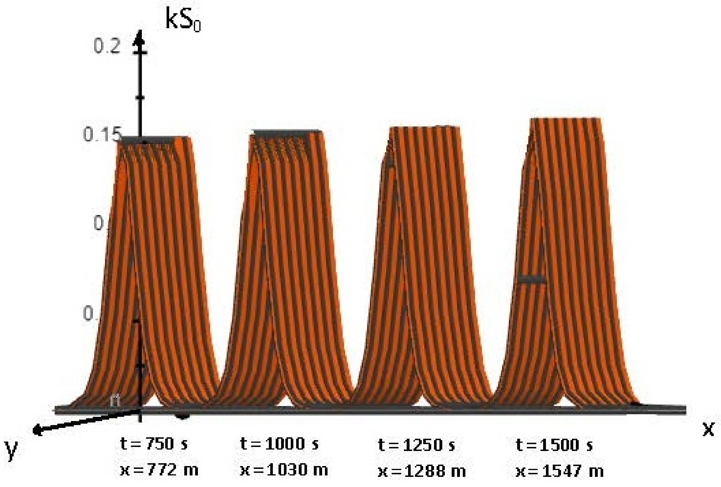
Using experimental data (44), the non dimensional expression ( k S 0 ) of the soliton solution of the SNG Equation (28), was plotted on an unscaled x-axis, for different times (Figure 2), and demonstrated an extremely slow continuous growth of ( k S 0 ). The growth rate was almost insignificant for a long period. It becomes observable after more than 1500 s.
The continuous growth of ( k S 0 ), leads to blow-up at finite time, t b 7008 s, which of course, is out of reach. Therefore, in this case, a significant growth in the soliton’s amplitude was not observable in experimental facilities, but it could be in situ. The growth rate of the soliton at different times and positions, for h = 0.26 m, and U 10 = 4.35 m / s , is given in (Table 2).

4. Conclusions

We derived a Serre-Green-Naghdi fully nonlinear, dispersive and antidissipative system of equations, in the context of the nonlinear dynamics of surface water waves under wind forcing, in finite depth. We found its soliton solution with amplitude, velocity and effective wave length increasing with time. Antidissipation due to wind action through the sheltering Jeffreys’ mechanism increases the amplitude of the solitary wave and leads to blow-up which occurs in finite time for infinitely large asymptotic space. This dispersive, anti-dissipative and fully nonlinear phenomenon is equivalent to the linear instability at infinite time. The blow-up time is not directly testable in existing experimental facilities. Indeed, soliton breaking must occur in finite space in a period prior to the blow-up. Focusing on experimental conditions and experimental data of IRPHÉ/Pythéas facilities (Branger et al. [30]), we established that for depth h = 0.14 m , and wind speed at 10 m U 10 = 4.82 m / s , the solitary wave travels 35 m in 40 s; hence, at the tunnel’s end, its growth rate reaches 0.09 . Likewise, for a depth of h = 0.26 m , and wind speed of 10 m U 10 = 4.35 m / s , the solitary wave travels 41 m in 40 s, which means that at the tunnel’s end, the growth rate is 0.02 only. It is clear that these growth rates are not measurable in IRPHÉ/Pythéas facilities. Nevertheless, in the case of h = 0.14 m , we believe that by gradually increasing the wind speed U 10 by up to 10 m / s , experimental confirmation of the present theory in existing experimental facilities could be obtained.
As noticed before, due to soliton blow-up being clearly impossible to probe experimentally, another interesting approach is to evaluate the solitary waves’ breaking time t d under specific wind forcing, and more generally during breaking conditions. There exist several breaking criteria among which the most widely known were introduced by (McCowan [31], Miche [32], Shemer [33]). It is of major importance to conduct further investigations in this direction.

Author Contributions

Both authors contributed equally to this manuscript. All authors have read and agreed to the published version of the manuscript.

Funding

This research received no external funding.

Institutional Review Board Statement

Not applicable.

Informed Consent Statement

Not applicable.

Data Availability Statement

Not applicable.

Conflicts of Interest

The authors declare no conflict of interest.

Appendix A

In this section, we prove Equation (24) by direct calculation.
We shall show that each of the constituent integrals of Equation (24), namely, + V 0 L ^ 1 V 1 d σ and + V 1 L ^ 1 V 0 d σ , is null. The nullity of the first of these integrals is shown explicitly. The nullity of the second one, can be obtained following the same procedure.
+ V 0 L ^ 1 V 1 d σ = + U 0 A ^ 1 U 1 + B ^ 1 S 1 + S 0 C ^ 1 U 1 + D ^ 1 S 1 d σ .
By expanding and slightly rearranging Equation (A1), the right hand side of Equation (A1) can be written as follows:
+ v S 0 U 1 , σ + U 0 U 1 , σ S 0 d σ + + U 0 v S 1 , σ + ( U 0 ) 2 S 1 , σ + g S 0 S 1 , σ d σ + + U 0 U 0 , σ S 1 d σ + + S 1 S 0 S 0 , σ [ v U 0 , σ σ + ( U 0 , σ ) 2 U 0 U 0 , σ σ ] ) d σ + + S 1 ( S 0 ) 2 3 v U 0 , σ σ σ + U 0 , σ U 0 , σ σ U 0 U 0 , σ σ σ d σ + + [ U 0 U 1 S 0 , σ + S 0 U 0 U 1 , σ + S 0 U 1 U 0 , σ + ( S 0 ) 2 S 1 , σ v U 0 , σ σ + ( U 0 , σ ) 2 U 0 U 0 , σ σ + ( S 0 2 ) S 0 , σ v U 1 , σ σ U 0 U 1 , σ σ U 1 U 0 , σ σ + 2 U 0 , σ U 1 , σ + 1 3 ( S 0 ) 3 v U 1 , σ σ σ U 0 U 1 , σ σ σ U 1 U 0 , σ σ σ + U 0 , σ U 1 , σ σ + U 1 , σ U 0 , σ σ + 1 3 S 1 ( S 0 ) 2 v U 0 , σ σ σ + U 0 , σ U 0 , σ σ U 0 U 0 , σ σ σ ] d σ .
It is clear to see that the first integral on the right hand side of the Equation (A2) is equal to zero. Indeed, it is sufficient to integrate in part using Equation (16a) and take into account the symmetric behaviour of S ( x , t ) and U ( x ; t ) at x = ± . The second integral on the right-hand side of the Equation (A2) can also be easily integrated in part. Using Equation (16b) and rearranging the terms, the remaining integrals in (A2) are:
+ 2 S 1 v U 0 , σ + U 0 U 0 , σ + g S 0 , σ d σ + + 1 3 S 1 ( S 0 ) 2 v U 0 , σ σ σ + 2 U 0 , σ U 0 , σ σ U 0 , σ U 0 , σ σ U 0 U 0 , σ σ σ d σ + + [ U 0 U 1 S 0 , σ + S 0 U 0 U 1 , σ + S 0 U 1 U 0 , σ + ( S 0 ) 2 S 1 , σ v U 0 , σ σ + ( U 0 , σ ) 2 U 0 U 0 , σ σ + ( S 0 ) 2 S 0 , σ v U 1 , σ σ U 0 U 1 , σ σ U 1 U 0 , σ σ + 2 U 0 , σ U 1 , σ + 1 3 ( S 0 ) 3 v U 1 , σ σ σ U 0 U 1 , σ σ σ U 1 U 0 , σ σ σ + U 0 , σ U 1 , σ σ + U 1 , σ U 0 , σ σ ] d σ ,
Integrating part the second integral of Equation (A3) and regrouping some of the terms, Equation (A3) becomes:
+ 2 S 1 v U 0 , σ + U 0 U 0 , σ + g S 0 , σ d σ + + 2 3 S 1 , σ ( S 0 ) 2 2 3 S 1 S 0 S 0 , σ v U 0 , σ σ + ( U 0 , σ ) 2 U 0 U 0 , σ σ d σ + + [ U 0 U 1 S 0 , σ + S 0 U 0 U 1 , σ + S 0 U 1 U 0 , σ + + ( S 0 ) 2 S 0 , σ v U 1 , σ σ U 0 U 1 , σ σ U 1 U 0 , σ σ + 2 U 0 , σ U 1 , σ + 1 3 ( S 0 ) 3 v U 1 , σ σ σ U 0 U 1 , σ σ σ U 1 U 0 , σ σ σ + U 0 , σ U 1 , σ σ + U 1 , σ U 0 , σ σ ] d σ
The third integral of Equation (A4) is a total differential and can be directly integrated. Using Equation (16b), the remaining integrals of Equation (A4) can be rearranged as follows:
+ S 1 v U 0 , σ + U 0 U 0 , σ + g S 0 , σ d σ + + 1 3 σ S 1 ( S 0 ) 2 v U 0 , σ σ + ( U 0 , σ ) 2 U 0 U 0 , σ σ d σ + 1 3 S 1 S 0 S 0 , σ v U 0 , σ σ + ( U 0 , σ ) 2 U 0 U 0 , σ σ d σ + + 1 3 S 1 , σ ( S 0 ) 2 v U 0 , σ σ + ( U 0 , σ ) 2 U 0 U 0 , σ σ d σ .
The second integral in Equation (A5) can be directly integrated. Furthermore, we integrate, in part, the last integral in Equation (A5). After regrouping similar terms, we obtained:
+ S 1 v U 0 , σ + U 0 U 0 , σ + g S 0 , σ d σ + S 1 S 0 S 0 , σ v U 0 , σ σ + ( U 0 , σ ) 2 U 0 U 0 , σ σ d σ + + 1 3 S 1 ( S 0 ) 2 v U 0 , σ σ σ + U 0 , σ U 0 , σ σ U 0 U 0 , σ σ σ d σ .
Equation (16b) implies the nullity of the sum of the three remaining integrals in Equation (A6). Hence, Equation (A1) becomes
+ V 0 L ^ 1 V 1 d σ = U 0 U 1 S 0 + 1 3 ( S 0 ) 3 v U 1 , σ σ U 0 U 1 , σ σ U 1 U 0 , σ σ + 2 U 0 , σ U 1 , σ + + U 1 v S 0 + U 0 S 0 + + S 1 v U 0 + ( U 0 ) 2 + g S 0 + + S 1 ( S 0 ) 2 v U 0 , σ σ + ( U 0 , σ ) 2 U 0 U 0 , σ σ + .
Finally, by taking into account the symmetric behaviour of S ( x , t ) and U ( x ; t ) at x = ± , and using Equations (16a) and (16b), we obtained:
+ V 0 L ^ 1 V 1 d σ = 0 .

References

  1. Jeffreys, H. On the formation of water waves by wind. Proc. R. Soc. A 1925, 107, 189–206. [Google Scholar]
  2. Jeffreys, H. On the formation of water waves by wind (Second paper). Proc. R. Soc. A 1926, 110, 241–247. [Google Scholar]
  3. Manna, M.A.; Montalvo, P.; Kraenkel, R.A. Finite time blow-up and breaking of solitary waves. Phys. Rev. E 2014, 90, 013006. [Google Scholar] [CrossRef] [PubMed] [Green Version]
  4. Korteweg, D.; de Vries, G. On the Change of Form of Long Waves Advancing in a Rectangular Canal, and on a New Type of Long Stationary Waves. Philos. Mag. 1895, 39, 422–443. [Google Scholar] [CrossRef]
  5. Whitham, G. Linear and Nonlinear Waves; Wiley: New York, NY, USA, 1974. [Google Scholar]
  6. Green, A.; Laws, N.; Naghdi, P.M. On the theory of water waves. Proc. R. Soc. A 1974, 338, 43–55. [Google Scholar]
  7. Green, A.; Naghdi, P.M. A Derivation of Equations for Wave Propagation in Water of Variable Depth. Fluid. Mech. 1976, 78, 237–246. [Google Scholar] [CrossRef]
  8. Benney, D.J. Long waves in liquid films. J. Math. Phys. 1996, 45, 150–155. [Google Scholar] [CrossRef]
  9. Johnson, R. Shallow water waves on a viscous fluid-the undular bore. Phys. Fluids 1972, 15, 1693–1699. [Google Scholar] [CrossRef]
  10. Grad, H.; Hu, P. Unified shock in plasma. Phys. Fluids 1967, 10, 2596–2602. [Google Scholar] [CrossRef]
  11. Hu, P. Collisional theory of shock and nonlinear waves in plasma. Phys. Fluids 1972, 15, 854–864. [Google Scholar] [CrossRef]
  12. Wadati, M. Wave propagation in nonlinear lattice. J. Phys. Soc. Jpn. 1975, 38, 673–680. [Google Scholar] [CrossRef]
  13. Karahara, T. Weak nonlinear magneto-acoustic waves in a cold plasma in the presence of effective electron-ion collisions. J. Phys. Soc. Jpn. 1970, 27, 1321–1329. [Google Scholar] [CrossRef]
  14. Jalali, M.R.; Borthwick, A. One-dimensional and two-dimensional Green-Naghdi equations for sloshing in shallow basins. Proc. Inst. Civ. Eng. Eng. Comput. Mech. 2017, 170, 49–70. [Google Scholar] [CrossRef] [Green Version]
  15. Le, T.T. Application of Green-Naghdi equations for a nonlinear stability of a tangential-velocity discontinuity in shallow water flow. J. Math. Methods Eng. 2019, 2, 1–5. [Google Scholar] [CrossRef]
  16. Dehghan, M.; Abbaszadeh, M. The solution of nonlinear Green-Naghdi equation arising in water sciences via a meshless method which combines moving kriging interpolation shape functions with the weighted essentially non–oscillatory method. Commun. Nonlinear Sci. Numer. Simul. 2019, 68, 220–239. [Google Scholar] [CrossRef]
  17. Sharifian, M.K.; Hassanzadeh, Y.; Kesserwani, G.; Shaw, J. Performance study of the multiwavelet discontinuous Galerkin approach for solving the Green-Naghdi equations. Int. J. Numer. Methods Fluids 2019, 90, 501–521. [Google Scholar] [CrossRef] [Green Version]
  18. Lannes, D.; Métivier, G. The shoreline problem for the one-dimensional shallow water and Green-Naghdi equations. J. l’École Polytech. Math. 2018, 5, 455–518. [Google Scholar] [CrossRef] [Green Version]
  19. Tkachenko, S.; Gavrilyuk, S.; Shyue, K. Hyperbolicity of the Modulation Equations for the Serre–Green–Naghdi Model. Water Waves 2020, 2, 299–326. [Google Scholar] [CrossRef] [Green Version]
  20. Latifi, A.; Manna, M.A.; Montalvo, P.; Ruivo, M. Linear and Weakly Nonlinear Models of Wind Generated Surface Waves in Finite Depth. J. Appl. Fluid Mech. 2017, 10, 1829–1843. [Google Scholar] [CrossRef]
  21. Su, C.; Gardner, C. Collisional theory of shock and nonlinear waves in plasma. J. Math. Phys. 1969, 10, 536–539. [Google Scholar] [CrossRef]
  22. Serre, F. Contribution à L’étude des écoulements Permanents et Variables Dans Les Canaux. La Houille Blanche 1953, 3, 830–872. [Google Scholar] [CrossRef] [Green Version]
  23. Dunkel, O. Some applications of Green’s theorem in one dimension. Bull. Am. Math. Soc. 1902, 8, 288–292. [Google Scholar] [CrossRef] [Green Version]
  24. Svendsen, I.A. Introduction to Nearshore Hydrodynamics; World Scientific: London, UK, 2005. [Google Scholar] [CrossRef]
  25. Chiang, C.M. The Applied Dynamics of Ocean Surface Waves; World Scientific: London, UK, 1992. [Google Scholar] [CrossRef]
  26. Darboux, G. Leçons sur la Théorie Générale des Surfaces; CreateSpace: Scotts Valley, CA, USA, 2016. [Google Scholar]
  27. Ott, E.; Sudan, R.N. Damping of Solitary Waves. Phys. Fluids 1970, 13, 1432–1434. [Google Scholar] [CrossRef]
  28. Ott, E.; Sudan, R.N. Nonlinear Theory of Ion Acoustic Waves with Landau Damping. Phys. Fluids 1969, 12, 2388–2394. [Google Scholar] [CrossRef]
  29. Manna, M.A.; Latifi, A.; Kraenkel, R.A. Green-Naghdi dynamics of surface wind waves in finite depth. Fluid Dyn. Res. 2018, 50, 025514. [Google Scholar] [CrossRef] [Green Version]
  30. Branger, H.; Manna, M.; Luneau, C.; Abid, M.; Kharif, C. Growth of surface wind-waves in water of finite depth: A laboratory experiment. Coast. Eng. 2022, 177, 104174. [Google Scholar] [CrossRef]
  31. McCowan, J. On the highest wave of permanent type. Philos. Mag. Ser. 5 1894, 38, 351–358. [Google Scholar] [CrossRef] [Green Version]
  32. Miche, R. Mouvement Ondulatoires de la Mer en Profondeur Constante ou Décroissante; École Nationale des Ponts et Chaussées: Marne-la-Vallée, France, 1944. [Google Scholar]
  33. Shemer, L. On kinematics of very steep waves. Nat. Hazards Earth Syst. Sci. 2013, 13, 2101–2107. [Google Scholar] [CrossRef] [Green Version]
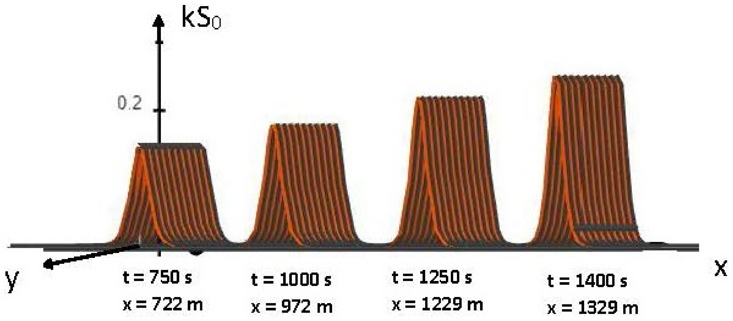
Figure 1. The non dimensional SGN soliton solution on a water surface at finite depth h = 0.14 m, with a wind speed of 10 m U 10 = 4.82 m/s, is plotted on an unscaled x-axis at times t = 750 s, t = 1000 s, t = 1250 s and t = 1400 s.
Fluids 07 00266 g001
Figure 2. The non dimensional SGN soliton solution on a water surface at finite depth h = 0.26 m, and the wind speed at 10 m U 10 = 4.35 m/s, is plotted on an unscaled x-axis at times t = 750 s, t = 1000 s, t = 1250 s and t = 1500 s.
Fluids 07 00266 g002
Table 1. The growth rate of the SNG solitary wave at different times and positions, for depth h = 0.14 m , and wind speed of 10 m U 10 = 4.82 m / s .
t(s)040750100012501400
x(m)03572297212291329
growth rate 0.090.150.5511.36
Table 2. The growth rate of the SNG solitary wave at different times and positions, for depth h = 0.26 m , and wind speed at 10 m U 10 = 4.35 m / s .
t(s)0407501000125015,000
x(m)041772103012881547
growth rate 0.020.060.080.10.12
Publisher’s Note: MDPI stays neutral with regard to jurisdictional claims in published maps and institutional affiliations.