Article

Experimental Observations on Flow Characteristics around a Low-Aspect-Ratio Wall-Mounted Circular and Square Cylinder

by
Seyed M. Hajimirzaie
Department of Civil and Environmental Engineering, IIHR—Hydroscience and Engineering, University of Iowa, Iowa City, IA 52242, USA
Present Address: Lead Engineer, Hydrology and Hydraulics, (H&H) Bureau, South Florida Water Management District (SFWMD), 3301 Gun Club Rd., West Palm Beach, FL 33406, USA.
Fluids 2023, 8(1), 32; https://doi.org/10.3390/fluids8010032
Submission received: 29 November 2022 / Revised: 10 January 2023 / Accepted: 13 January 2023 / Published: 15 January 2023
(This article belongs to the Special Issue Challenges and Directions in Fluid Structure Interaction)

Abstract

:
The mean wake structures of a cube (square cylinder) and circular cylinder of height-to-width aspect ratio 1.0, at a Reynolds number of 1.78 × 10⁴ based on the obstacle width, were investigated experimentally. The boundary-layer thickness was 0.14 of the obstacle height. The study was performed using thermal anemometry and two-dimensional digital particle image velocimetry (DPIV). Streamwise structures observed in the mean wake for both cylinders included well-known tip- and horseshoe (HS)-,vortex pairs as well as additional structures akin to the base vortices. In addition to tip-, base-, and HS-vortices, in the near wake of the cube, two more counter-rotating pairs of streamwise structures, including upper and inboard vortices, were observed. The existence of base vortices formed in the near wake for both obstacles is a unique observation and has not been previously reported for such low-aspect-ratio obstacles in thin boundary-layers. A model of arch-vortex evolution was proposed, in which arch structures were deformed by the external shear-flow to explain the observed base-vortices in the cylinder wake. A weak dominant-frequency of St = f0D/U∞ = 0.114 was observed across the height for the cube, while no discernible spectral peaks were apparent in the wake of the cylinder. Cross-spectral analysis revealed the shedding to be symmetric (in-phase) arch-type for the cylinder and predominantly anti-symmetric (out-of-phase) Karman-type for the cube. The study makes fundamental contributions to the understanding of the flow-field surrounding low-aspect-ratio cylinders.

1. Introduction

Wall-mounted cylinders in boundary-layer flows are ubiquitous in numerous natural systems and engineering applications such as buildings and exhaust stacks. Despite their geometric simplicity, the flow field around a single wall-mounted cylinder in a boundary-layer is incredibly complex, unsteady, and highly three-dimensional [1,2].
The wake structures, vortex-shedding behavior, and parameters governing the flow fields around wall-mounted cylinders including aspect ratio (AR), boundary-layer characteristics, and Reynolds number have been studied extensively [1,2,3,4,5]. Several studies have shown that the near wake of finite cylinders extending from a stationary wall mainly depend on the aspect ratio, AR = H/D, where H and D are the height and the width (or diameter) of the cylinder, respectively [4,5]. When H/D is less than critical value, which has been reported as being from one to seven in different studies [5], vortex-shedding from the sides of the cylinder changes from the anti-symmetrical Karman type to the symmetric arch type.
While wake components of square-cross-section cylinders of AR ≥ 3 have been investigated most extensively [1,2,3,4,5,6,7], to the author’s knowledge, studies that show the wake structures of low-aspect-ratio (AR ≤ 1) square and circular cylinders are scarce in the literature.
Pattenden et al. [8] showed that the mean flow-structure around circular cylinder of AR = 1 is characterized by three dominant features: (1) a horseshoe (HS)-vortex that forms at the junction upstream of the obstacle, (2) the streamwise tip-vortices that induce a downwash in the wake, and (3) the arch-vortices shed from the obstacle sides and connected near the free end. In addition to these three vortex structures, for higher aspect-ratio obstacles (AR > 3), base-vortices may be observed in the mean flow, close to the obstacle-wall junction plane, which induces an upwash on the symmetry plane of the wake [1,4]. However base structures are much less robust than the tip and HS structures and the conditions of their existence are not well-understood. Sumner et al. [4] reported base-vortices for cylinders of aspect ratios of 5, 7, and 9 but not for AR = 3.
Hajimirzaie [9] reviewed the wake structures and shedding-dynamics of wall-mounted bodies of aspect ratio of O(1). A review of research on the origins of tip- and base-vortices demonstrate that the wake structures of obstacles of aspect ratio of O(1) can be highly varied, depending on obstacle’s shape and flow conditions (Reynolds number, boundary-layer thickness relative to the obstacle height (δ/H) or width (δ/D)).
For high-aspect-ratio cylinders, when both tip- and base-vortices are present, studies by Hosseini et al. [3] suggested that the tip- and base-vortices were projections of the Karman-shedding connecting to the next newly shed structure. However, there is a lack of consensus in the literature regarding the mean wake-components of low-aspect-ratio cylinders [9,10].
For circular cylinders of AR = 0.67 and 0.89, Hajimirzaie [9] showed streamwise-vortices of opposite-sign (similar to base-vortices that create upwash) form in the near wake, just below the tip structures (Figure 1). To the author’s knowledge, this was the first observation of base-like vortices in the wakes of low-aspect-ratio cylinders in a thin laminar boundary-layer (δ/D = 0.14) especially when AR < 1.0. The wake of cylinder of AR = 0.89 (Figure 1a) also contains a tertiary-vortex near the base plane. The origin of the base- (or tertiary-vortices) and their relationship with the other structures in the wake remained unclear, and motivate this study.
The present study contributes to the general knowledge of the flow and vortex structure around wall-mounted square- and circular-cross-section cylinders. It is also important to note that most of the data on low-aspect-ratio cylinders provided by previous research were collected in fully turbulent boundary-layer flow compared to a thin laminar boundary-layer investigated here.

2. Experimental Setup and Methods

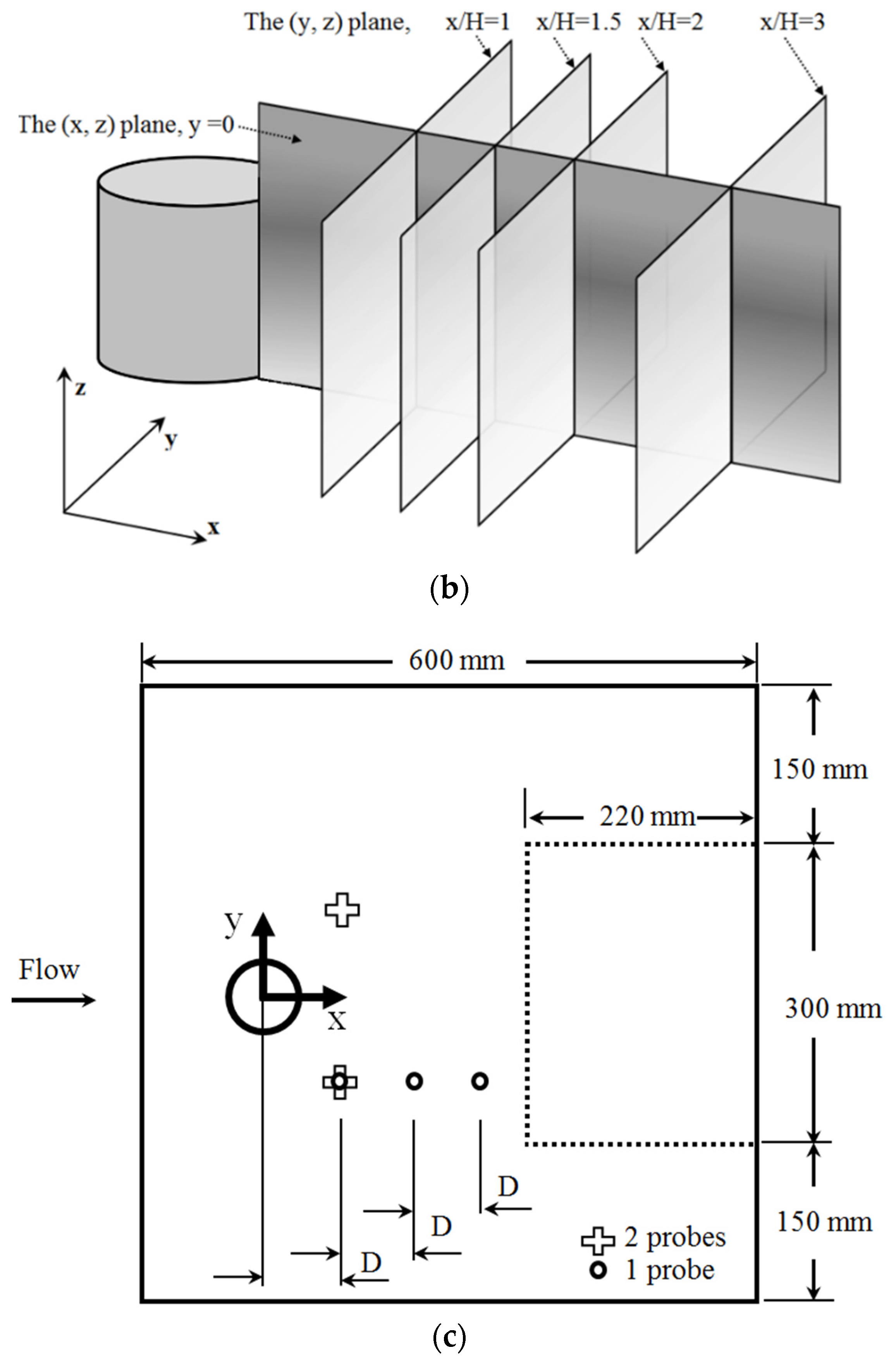
A wall-mounted cube (square cylinder) and circular cylinder of diameter, D = 50 mm, and aspect ratio, AR = H/D = 1.0, were investigated in a thin boundary layer. The measurement methods and experimental setup were the same as in the prior studies by the author [9,10]. The experiments were performed in a free-surface water channel of width 0.6 m, depth 0.3 m, and length 10.0 m. Cylinders were mounted 152 mm from the leading edge of the base plate, and the unperturbed boundary-layer thickness at this location was δ99/D = δ99/H = 0.14. A schematic of the setup is shown in Figure 2. A short acrylic plate was placed on the free surface to allow optical access from above the water channel. The Reynolds number based on D and U∞ = 0.35 m s−1 was ReD = U∞D/ν = 17,800.
Measurements were conducted using two-dimensional DPIV. A LaVision Flowmaster system consisted of a dual-cavity Litron Nano Nd:YAG laser with a maximum power-output of 200 mJ per pulse, a CCD camera with a frame rate of 7.2 Hz and resolution of 2048 × 2048 pixels, and a PC-based timing and data-acquisition system controlled by LaVision DaVis 8.1.2 software.
Measurements of the vortex-shedding frequency were obtained using a TSI IFA-300 anemometer and a hot-film probe (TSI model 1210-20).
Cross-correlation functions were calculated via two single hot-film probes, which were installed in parallel at x/D = 1, y/D = ±1, and 0.25 ≤ z/H ≤ 1 along the cylinders. More details of the experimental set-up, measurement techniques, and estimations of uncertainties can be found in the prior studies by the author [9,10].

3. Results

This section is organized as follows. Section 3.1 presents the mean velocity-fields downstream of obstacles. Section 3.2 and Section 3.3 present the mean vorticity-fields in the vicinity of the cube and cylinder, respectively, which allow the characterization of flow-field properties. Section 3.4 examines the shedding characteristics and unsteadiness in the wake of both obstacles.

3.1. Flow Patterns in the Streamwise Symmetry-Plane

Figure 3 contains the mean streamlines downstream of the obstacles. The reattachment lengths (Xr) on the symmetry plane measured from the center of the obstacle and non-dimensionalized by the obstacle diameter or width are Xr/D = 1.95 and 2.0 for the cube and cylinder, respectively. For comparison, Pattenden et al. [8] found Xr/D = 1.6 for a circular cylinder of AR = 1 at ReD = 20 × 104. Hajimirzaie et al. [10] reported Xr/D = 2.0 and 1.63 for cylinders of AR = 0.89 and 0.67, respectively, at ReD = 1.78 × 10⁴. Gildersleeve and Amitay [11] reported Xr/D = 1.75 for a circular cylinder of AR = 1 at ReD = 2.03 × 10⁴.
The locations of the reattachment point over the top (free end) of the cylinders show that reattachment occurs very close to the leading edge for the cube (Figure 3a). The reattachment locations over the top are in good agreement with what is reported in the literature [11].

3.2. Flow Patterns in the Wake of Cube

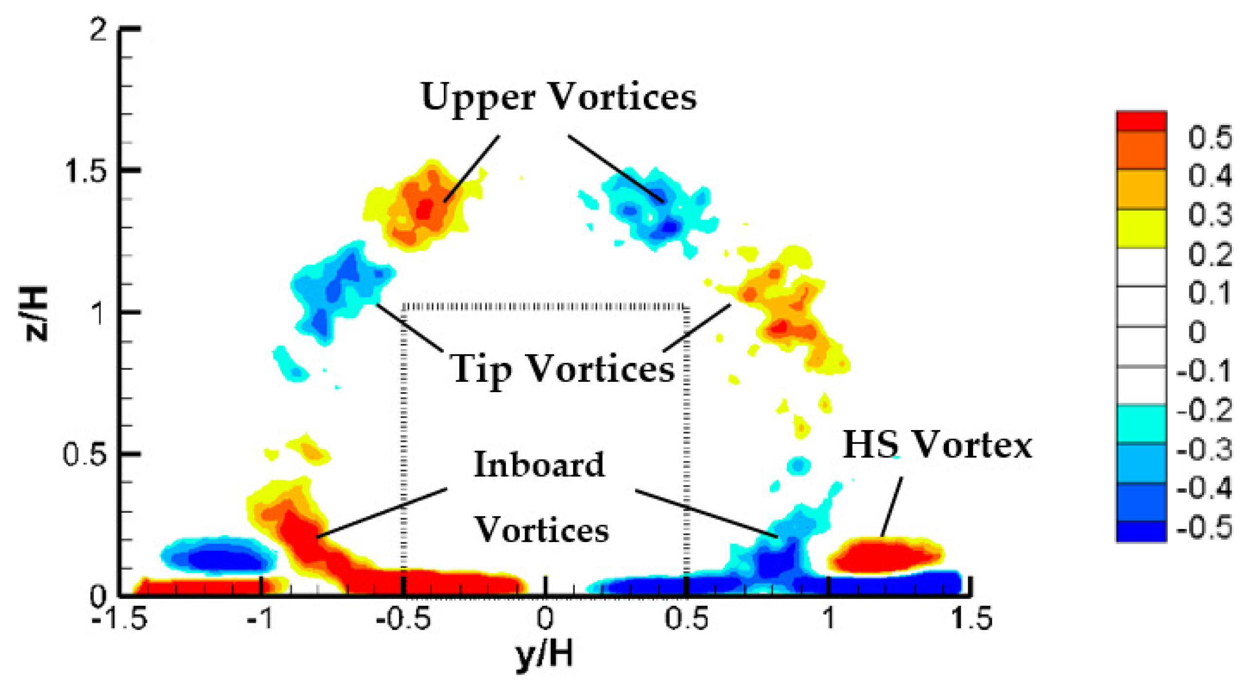
Figure 4 displays isocontours of streamwise dimensionless-vorticity ( ω x *   = ω x H / U ) in the wake of the cube between x/H = x/D = 0 and 3. Each mean vorticity-field was obtained from 3000 instantaneous velocity-fields.
In the near wake of the cube, complex systems of counter-rotating pairs of streamwise structures are visible, probably due to roll-up of the separated shear layers from the sharp leading-edge of the cube. The streamwise-vorticity distribution in the wake at x/D = 0 and 0.5 (Figure 4a,b) consists of several streamwise structures: counter-rotating tip-vortices inducing downwash, horseshoe-vortices (HS), and a pair of vortices near the base and inboard of the HS-vortex legs, therefore named as “inboard” vortices. In addition, another pair of vortex structures, named upper-vortices, is visible in the upper wakes of the cube between the tip-vortices inducing upwash. The existence of the upper-vortices is controversial in the existing literature, and is questioned by several studies including Pattenden et al. [8], Palau-Salvador et al. [12], and Krajnovic [13]. To the authors’ knowledge, the only other studies that have noted the existence of upper-vortices are Roh and Park [14] and Hain et al. [15], who conducted their experiments over a circular cylinder of AR = 1.25 (ReD = 5.92 × 10³ and 1.48 × 10⁵) and AR = 2.2 (ReD = 1.0 × 10⁵), respectively.
At x/D = 1.0 (Figure 4c), in addition to four noted vortices at x/D = 0.5, an unprecedented pair of counter-rotating streamwise base-like vortices or upwash are visible. The existence of base-vortices in x/D = 1.0 and 1.5 (Figure 4c,d) is surprising, and further investigation is required to find their origin. This will be described later, in Section 4.
At x/D = 1.5 (Figure 4d), the base-like vortices remain in approximately the same vertical position, but the tip-vortices are sheared toward the base plane. Further downstream at x/D = 2.0 and 3.0 (Figure 4e,f), the tip and horseshoe structures combine near the base plane and create other streamwise structures named the trailing-vortices, as shown in Pattenden et al. [8] as well.

3.3. Flow Patterns in the Wake of Cylinder

Figure 5 displays isocontours of streamwise dimensionless-vorticity ( ω x * = ω x H / U ) in the wake of the cylinder between x/H = 0 and 3.0. Each mean vorticity-field was obtained from 3000 instantaneous velocity-fields. Comparison with Figure 3b indicates that the planes at x/D < 1.5 fall within the recirculation region.
In the near wake of the cylinder at x/D = 0 and 0.5, similar to the cube, the well-known tip- and HS-vortices are visible (Figure 5b). In addition, a weak pair of base-like vortices is visible at x/D = 1 (Figure 5c). It is plausible that these base structures are generated by the deformation of arch structures shed into the wake, as described in Hajimirzaie et al. [10]. Further investigation is required to find their origin, as later described in a discussion of the dynamics of the wakes, in Section 4.
At x/D = 1.0, the wake of the cylinder also contains a tertiary-vortex (of the same sign as the tip-vortices) below the base-vortices near the base plane. A similar observation was reported [9] for the cylinder of AR = 0.89 (Figure 1a). At x/D = 1.5, the tip-vortices are moved toward the base plane. Furthermore, the tertiary-vortex is no longer evident in the wake.
Further downstream at x/D = 2.0 and 3.0, similar to the cube’s wake at this location, the tip- and the horseshoe-vortices combine and form trailing-vortices, as shown in Pattenden et al. [8].
In general, the tip-vortices shed by the cylinder are much stronger than for the cube, as a comparison of Figure 4b and Figure 5b demonstrates. Furthermore, whereas Sumner et al. [4] observed the tip-vortices weakening with increasing downstream distance, for the cylinder, there are increases—see for instance tip-vortices in Figure 5b vs. 5c. The dimensionless circulations, Γ = Γ/(UD), of each structure in the wake were computed but not discussed, for brevity.

3.4. Shedding Characteristics

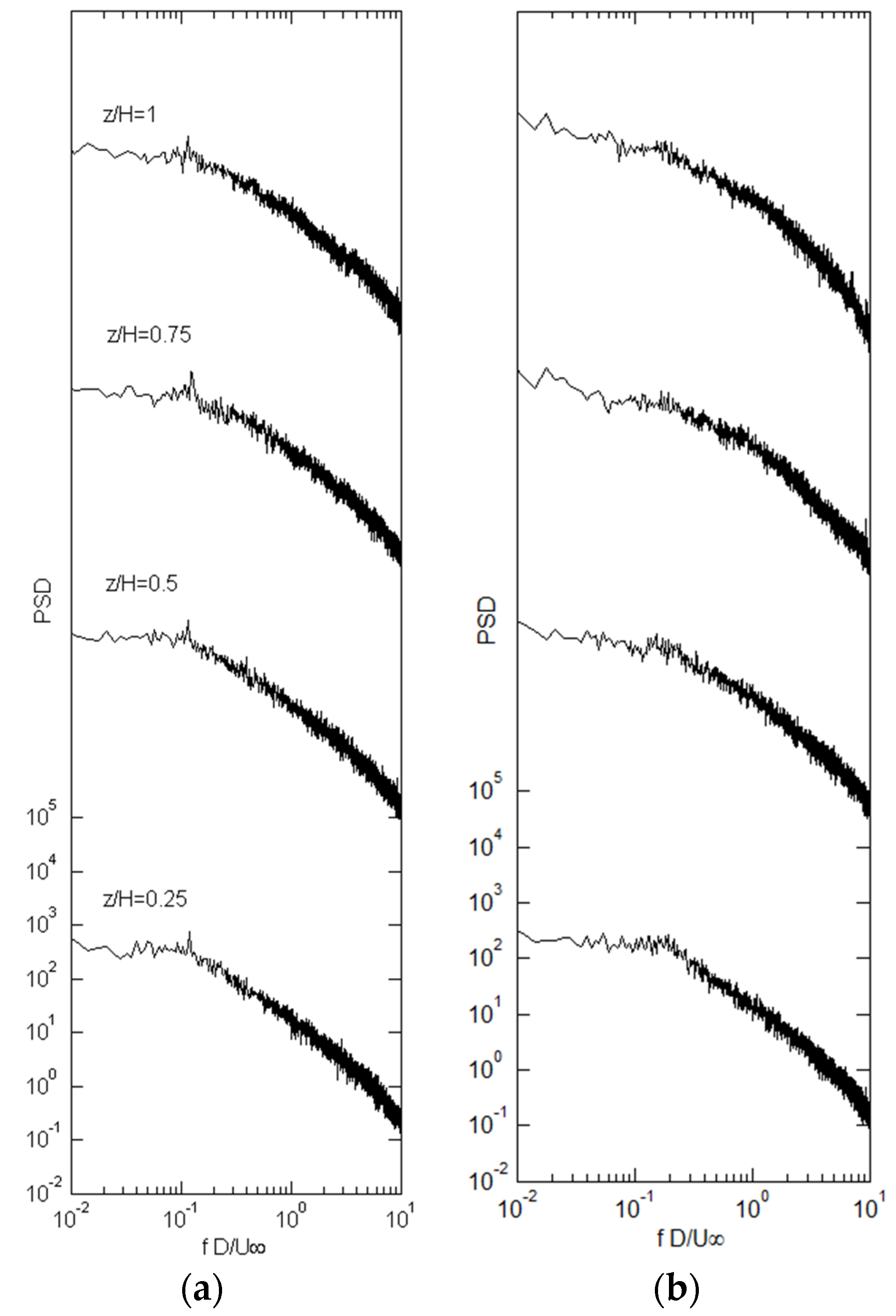
Figure 6 illustrates the power-spectral-density function (PSD) of the streamwise velocity for a cube and cylinder.
For the cube, a peak is visible (Figure 6a) across the height with St = f0D/U∞ = 0.114 (f0 = dominant frequency = 0.798 Hz), while no spectral peaks are visible in the wake of the cylinder along the height. For a circular cylinder of AR = 1 at ReD = 4.7 × 10⁴ and δ/D = δ/H = 0.057, Okamoto and Sunabashiri [16] reported a spectral peak around St = 0.23. Ata similar Reynolds number, Okamoto and Uemura [17] reported St = 0.112 for a cube (which is very similar to the weak dominant-frequency observed in this study) and 0.225 for a cylinder of AR = 1 in a slightly thicker boundary-layer (δ/D = δ/H = 0.086). For a circular cylinder of AR = 1, Pattenden et al. [8] reported St = 0.09 at δ/D = 0.1 and a ReD = 1.96 × 10⁵ and Gildersleeve and Amitay [11] reported St = 0.14 at δ/D = 1.0 and ReD = 2.03 × 10⁴.
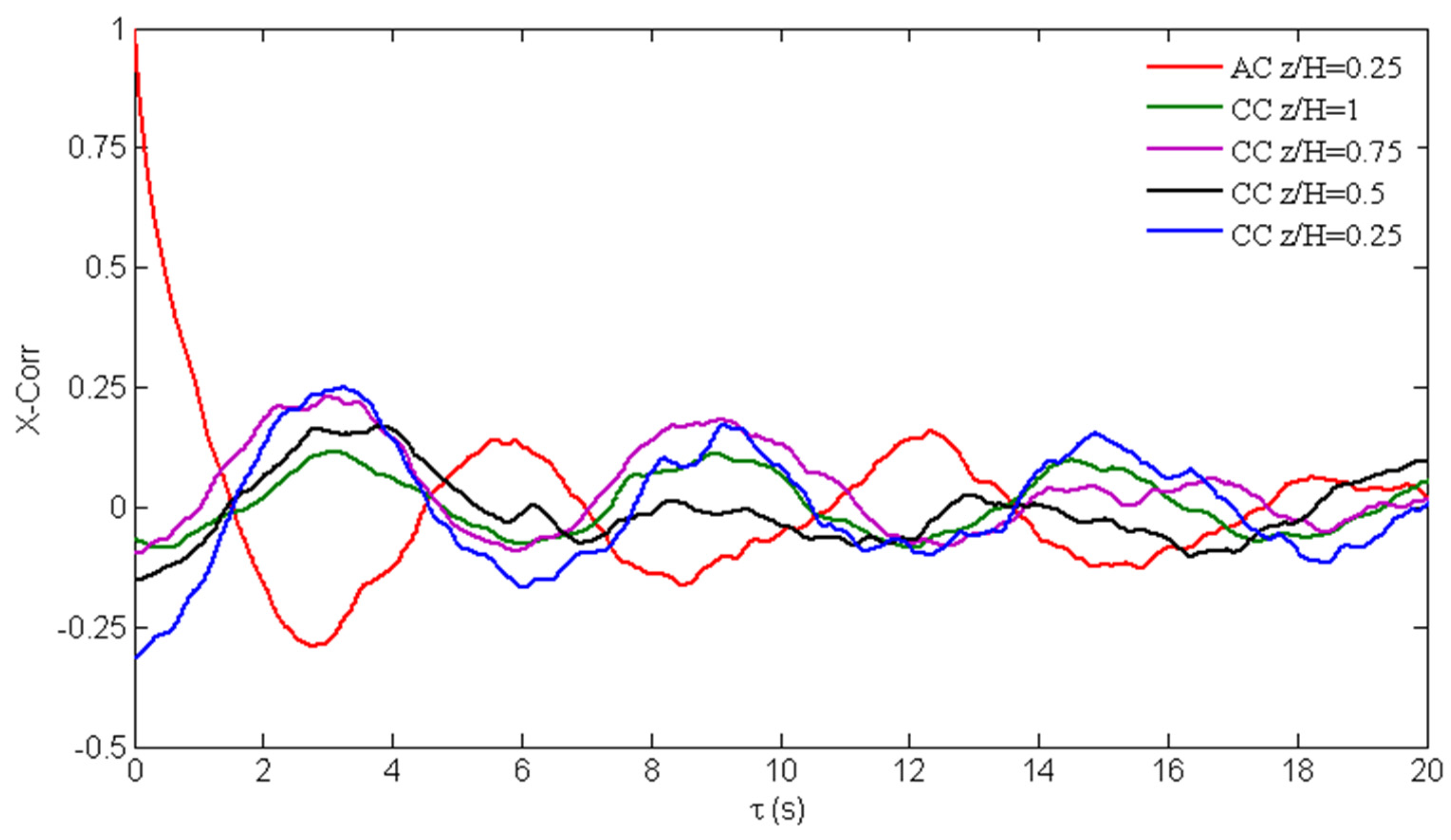
Figure 7 shows cross-correlations of streamwise velocity-fluctuations for measurements at symmetric positions (Figure 2c) in the wake of the cube at x/H = 1.0, y/H = ±1, and 0.25 ≤ z/H ≤ 1. The autocorrelation function at x/H = 1.0, y/H = 1.0, and z/H = 0.25 is also shown, for reference. The spatial cross-correlations, s = 0 sec, are negative for all the vertical positions, indicating approximately out-of-phase (antisymmetric) shedding on opposite sides of the cube, resembling the Karman-shedding. For the cylinder (not shown, for brevity), the spatial cross-correlations are positive for each wall-normal position, showing that wake oscillations at symmetric positions in the wake are approximately in-phase.

4. Discussion

Based on the previous work reviewed in Section 1, it is expected that the mean flow in the near wake of low-aspect-ratio cylinders would be characterized by the arch-vortex, consisting of the mean spanwise-vortices shed from the obstacles’ sides. While this, to some extent, is correct for the cylinder, the existence of upper- and inboard-vortices (e.g., Figure 4b) in the wake of the cube showed that arch-type shedding (at least from a time-averaged perspective) does not fit well with the present measurements. The wake structure of the cube is necessarily more complex than that of the circular cylinder with the same aspect ratio (AR = 1).
Models for higher-aspect-ratio bodies presented in the literature [1,3,4] suggest that tip and base structures are streamwise projections of Karman vortices. These proposed models do not fit well with the present observations, in the wake of the cylinder/cube investigated here. Opposite to high-aspect-ratio cylinders, it seems that base-vortices here (Figure 4c and Figure 5c) are not a projection of Karman vortices, for the following reasons: (1) tip and base structures often appear near each other, and (2) there is a vast disparity in the strengths of tip- and base-vortices. The wake model presented by Pattenden et al. [8] for a low-aspect-ratio cylinder also does not account for the presence of base (upwash) structures observed in either the cube or the cylinder.
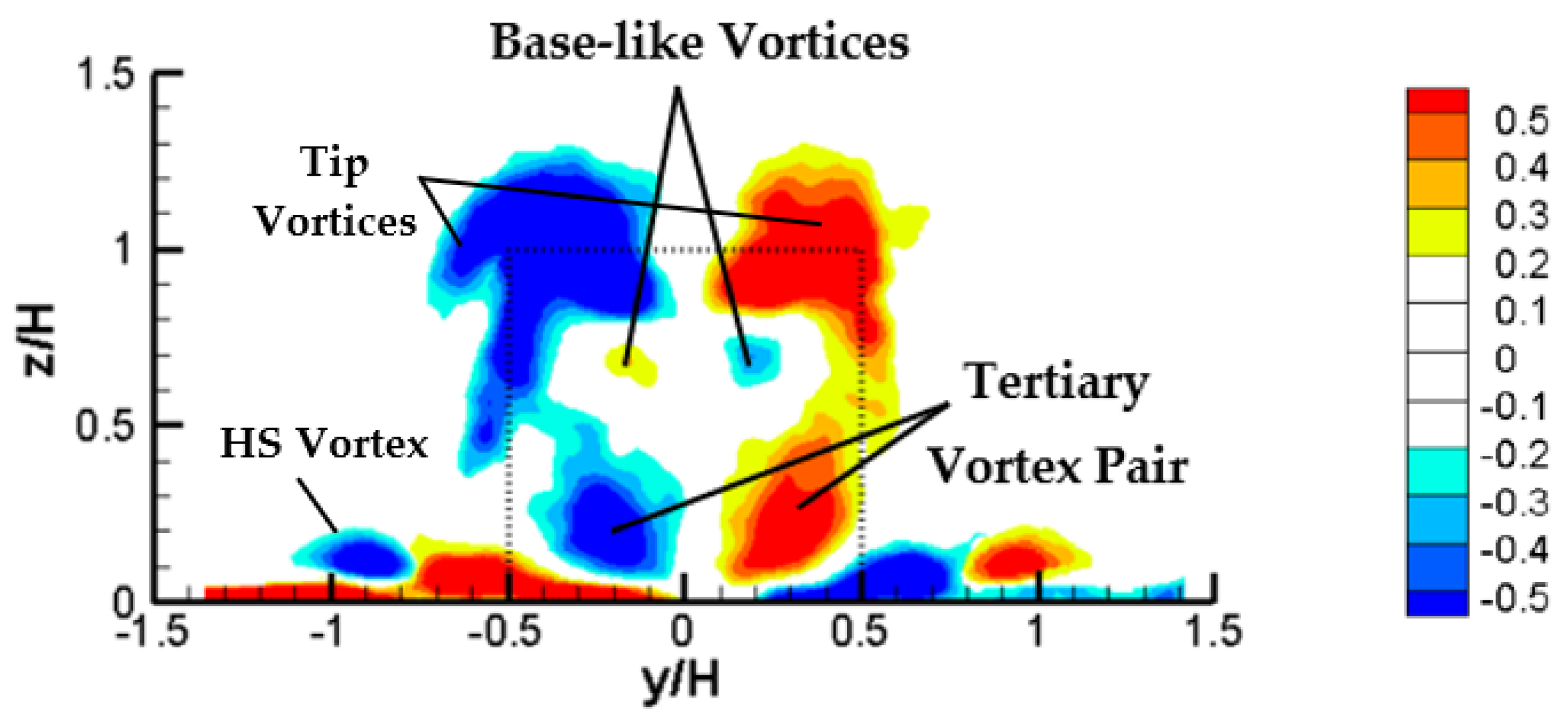
In the wake of the cylinder, using the identified structures in Figure 8 as a basis, a possible model for the vortex structure in the wake is proposed. Since there is no source of vorticity away from the boundaries, the existence of the base structures in the wake (Figure 4c) must be explained by a tilting of vorticity into the streamwise orientation, as described by Hajimirzaie et al. [10]. A vortex skeleton model of the wake by Hajimirzaie et al. [10] showed that the presence of dominant upwash (base) or downwash (tip) in the wakes of the transverse and streamwise ellipsoids, respectively, can be attributed to the tilting of the arch-vortex tips downstream or upstream. The mean flow in the near wake of the cylinder is characterized by three dominant features: (1) a horseshoe-vortex, (2) the streamwise tip-vortices, and (3) the arch-vortex, with tips tilted in the downstream direction (source of observed base structures) due to the action of the mean flow-shear.
As Figure 8 shows, the cylinder wake also contains a tertiary vortex (of the same sign as the tip-vortices) near the base plane. The author surmises that this is related to a higher-order bending instability in the vertical legs of the arch structures. This may also be explained by competing spanwise- and axial-vorticity components associated with the arch and tip-vortices. This may lead to the development of the tertiary-vortex pair.
It should be noted that the author does not believe that the results presented here are in contradiction to those of Pattenden et al. [8]. A key difference that separates the two studies is that their Reynolds number is an order of magnitude higher. The effects of the Reynolds number on the wake components have been reported by several studies [18,19,20,21].
Using the identified structures in Figure 9 as a basis, a possible model for the vortex structure in the wake of the cube is proposed. Furthermore, some insight into the physical mechanisms responsible for the provenance of the identified vortex structures around the cube is suggested. As Figure 7 shows, oscillations at symmetric positions are approximately out of phase (Karman-type vortices). Therefore, it can be deduced that the tip- and inboard-vortices are projection of Karman vortices. These structures are locally comparable to the Karman vortices observed by Wang and Zhou [1] and the full-loop structure described by Bourgeois et al. [22]. However, the source of base-vortices in the wake of the cube (Figure 4c,d) remained unknown. Further analysis is required for determining the exact mechanism that generates the base-vortices.
The upper-vortices observed in wake of the cube appear to coincide more closely with the observations of Roh and Park [14] and Hain et al. [15], who reported the existence of two foci as a source of vortex pairs spatially coincident with the mean tip-vortices near the free end of circular cylinders. While some studies [8,12,13] showed that the proposed model by Roh and Park [14] for the free-end flow field of a low-aspect-ratio, wall-mounted circular cylinder differs topologically from other models in the literature, the existence of upper-vortices in the wake of the cube here (Figure 4b) is consistent with Roh and Park’s observation. A similar observation was made by Gildersleeve and Amitay [11].

5. Summary and Conclusions

Experimental studies that show the evolution of flow structures in the wake of low-aspect-ratio cylinders are scarce in the literature. This work, using 2-D particle-image-velocimetry (DPIV) and thermal anemometry, presents the vortex structures that develop in the wake of square- and circular-cross-section cylinders of aspect ratio AR = H/D = 1.0 in a thin laminar boundary-layer (δ/D = 0.14).
Mean streamwise-structures observed in the wake for both obstacles include well-known tip- and HS-vortex pairs. Streamwise-vortices similar to the base-vortices (upwash) also form in the near wake for both obstacles. The existence of base-vortices is a unique observation and has not been previously reported for low-aspect-ratio cylinders in thin boundary-layers with a thickness significantly smaller than the obstacle dimensions. This observation (Figure 4c and Figure 5c) illustrates that the base-vortex pairs in both cube and cylinder wakes appear very high—near the tip-vortices, which is inconsistent with the explanation for the source of base-vortices in the literature, e.g., [1,4].
For the cube (square cylinder), in addition to tip-, HS-, and base-vortices, complex systems of counter-rotating pairs of streamwise structures including upper- and inboard-vortices were observed. It was proposed that the tip- and inboard-vortices were projections of Karman vortices, comparable to the Karman vortices observed by Bourgeois et al., [22] named as the full-loop structure. However, the source of base-vortices in the mean flow-field could not be satisfactorily explained—at least from a time-averaged perspective. The existence of upper-vortices in the wake of the cube (Figure 4b), albeit controversial in the existing literature and questioned by several studies, appears to coincide more closely with the observation of Roh and Park [14] and Hain et al. [15].
For the circular cylinder, the wake was characterized by arch-vortices with tips tilted in the downstream direction, due to the mean flow-shear. The downstream-tilting arch-vortices were evident as a pair of counter-rotating base-vortex structures that induced upwash in the cylinder’s wake.
Point-velocity measurements in the wake identified a dominant frequency of St = 0.114 across the height for the cube, while no discernible spectral peaks were apparent in the wake of the cylinder, along the height. Cross-correlations of velocity fluctuations for measurements at symmetric positions in the wake of both obstacles revealed that the shedding was symmetric (in-phase) arch-type for the cylinder and predominantly out-of-phase (anti-symmetric) Karman-type for the cube.
With the cylinder’s broad potential applications, there exists a strong need for an accurate wake model to represent the flow-field associated with low-aspect-ratio cylinders. While the mean wake-structure around the obstacle of interest is reported here, many details of the dynamics of these wakes are still unknown. Further investigation is required to obtain a full picture of the wake topology. In particular, these fundamental questions need to be addressed in future studies into low-aspect-ratio cylinders:
(1)
Is the base-vortex connected with other known vortical structures in the mean flow-wake?
(2)
What is the nature of the base-vortices in low-aspect-ratio cylinders and their interactions with the instantaneous flow-structures?
(3)
Must base-vortices exist concurrently with anti-symmetric Karman-shedding, assuming the existence of intermittent Karman-shedding?
Conditional averaging of DPIV data can be employed at constant phases of the vortex-shedding, to better understand the wake dynamics.

Funding

This work was supported by the National Science Foundation (NSF) under award number CBET-1033732.

Data Availability Statement

Not applicable.

Acknowledgments

I would like to express my deep gratitude to James Buchholz, my Ph.D. supervisor (University of Iowa), for his assistance throughout all aspects of this study. Three reviewers are also thanked for helpful comments which have strengthened the paper.

Conflicts of Interest

The author declares no conflict of interest.

Abbreviations

x: y, zStreamwise, transverse (lateral), and spanwise (vertical or wall-normal) directions
ARAspect Ratio = H/D = 1.0
HObstacle height (mm) = 50
DObstacle diameter (mm) = 50
dFlow depth above the base plate (mm) = 175
RSRelative submergence = d/H = 3.5
δ99/DRelative thickness of the boundary-layer = 0.14
U∞Free-stream velocity (m/s) = 0.35
ReDReynolds number = U∞D/υ
υKinematic viscosity (m2/s)
fFrequency of velocity fluctuations in the wake (Hz)
fD/U∞Dimensionless frequency
f0Dominant frequency
StStrouhal number = f0D/U∞
ωVorticity (s−1)
ω*Dimensionless vorticity, ω* = ωD/U∞
ΓCirculation (mm2/s)
Γ*Dimensionless circulation Γ* = Γ/(U∞D)

References

  1. Wang, H.F.; Zhou, Y. The finite-length square cylinder near wake. J. Fluid Mech. 2009, 638, 453–490. [Google Scholar] [CrossRef] [Green Version]
  2. Kindree, M.G.; Shahroodi, M.; Martinuzzi, R.J. Low-frequency dynamics in the turbulent wake of cantilevered square and circular cylinders protruding a thin laminar boundary layer. Exp. Fluids 2018, 59, 186. [Google Scholar] [CrossRef]
  3. Hosseini, Z.; Bourgeois, J.A.; Martinuzzi, R.J. Large Scale Structures in Dipole and Quadrupole Wakes of a Wall Mounted Finite Rectangular Cylinder. Exp. Fluids 2013, 54, 1595–1610. [Google Scholar] [CrossRef]
  4. Sumner, D.; Heseltine, J.L.; Dansereau, P. Wake structure of a finite circular cylinder of small aspect ratio. Exp. Fluids 2004, 37, 720–730. [Google Scholar] [CrossRef]
  5. Yauwenas, Y.; Porteous, R.; Moreau, D.J.; Doolan, C.J. The effect of aspect ratio on the wake structure of finite wall-mounted square cylinders. J. Fluid Mech. 2019, 875, 929–960. [Google Scholar] [CrossRef]
  6. Essel, E.; Tachie, M.; Balachandar, R. Time-resolved wake dynamics of finite wall-mounted circular cylinders submerged in a turbulent boundary layer. J. Fluid Mech. 2021, 917, A8. [Google Scholar] [CrossRef]
  7. Crane, R.; Popinhak, A.; Martinuzzi, R.; Morton, C. Tomographic PIV investigation of vortex shedding topology for a cantilevered circular cylinder. J. Fluid Mech. 2022, 931, R1. [Google Scholar] [CrossRef]
  8. Pattenden, R.J.; Turnock, S.R.; Zhang, Z. Measurements of the flow over a low-aspect-ratio cylinder mounted on a ground plane. Exp. Fluids 2005, 39, 10–21. [Google Scholar] [CrossRef]
  9. Hajimirzaie, S.M. Flow Structure in the Wake of a Low-Aspect-Ratio Wall-Mounted Bluff Body. Ph.D. Thesis, University of Iowa, Iowa City, IA, USA, 2013. [Google Scholar] [CrossRef] [Green Version]
  10. Hajimirzaie, S.M.; Wojcik, C.J.; Buchholz, J.H.J. The role of shape and relative submergence on the structure of wakes of low-aspect-ratio wall-mounted bodies. Exp. Fluids 2012, 53, 1943–1962. [Google Scholar] [CrossRef]
  11. Gildersleeve, S.; Amitay, M. Vortex dynamics of a low aspect ratio cantilevered cylinder immersed in a boundary layer. J. Fluid Mech. 2020, 901, A18. [Google Scholar] [CrossRef]
  12. Palau-Salvador, G.; Stoesser, T.; Fröhlich, J.; Kappler, M.; Rodi, W. Large eddy simulations and experiments of flow around finite-height cylinders. Flow Turbul. Combust. 2010, 84, 239. [Google Scholar] [CrossRef]
  13. Krajnovic, S. Flow around a tall finite cylinder explored by large eddy simulation. J. Fluid Mech. 2011, 676, 294–317. [Google Scholar] [CrossRef] [Green Version]
  14. Roh, S.; Park, S. Vortical flow over the free end surface of a finite circular cylinder mounted on a flat plate. Exp. Fluids 2003, 34, 63–67. [Google Scholar] [CrossRef]
  15. Hain, R.; Kahler, C.J.; Michaelis, D. Tomographic and time resolved PIV measurements on a finite cylinder mounted on a flat plate. Exp. Fluids 2008, 45, 715–724. [Google Scholar] [CrossRef]
  16. Okamoto, S.; Sunabashiri, Y. Vortex shedding from a circular cylinder of finite length placed on a ground plane. ASME J. Fluids Eng. 1992, 112, 512–521. [Google Scholar] [CrossRef]
  17. Okamoto, S.; Uemura, N. Effect of rounding side-corners on aerodynamic forces and turbulent wake of a cube placed on a ground plane. Exp. Fluids 1991, 11, 58–64. [Google Scholar] [CrossRef]
  18. Da Silva, B.L.; Chakravarty, R.; Sumner, D.; Bergstrom, D.J. Aerodynamic forces and three-dimensional flow structures in the mean wake of a surface mounted finite-height square prism. Int. J. Heat Fluid Flow 2020, 83, 108569. [Google Scholar] [CrossRef]
  19. Cao, Y.; Tamura, T.; Zhou, D.; Bao, Y.; Han, Z. Topological description of near-wall flows around a surface-mounted square cylinder at high Reynolds numbers. J. Fluid Mech. 2022, 933, A39. [Google Scholar] [CrossRef]
  20. Rastan, M.R.; Sohankar, A.; Alam, M.M. Low-Reynolds-number flow around a wall-mounted square cylinder: Flow structures and onset of vortex shedding. Phys. Fluids 2017, 29, 103601. [Google Scholar] [CrossRef]
  21. Wang, H.F.; Zhou, Y.; Chan, C.K.; Lam, K.S. Effect of initial conditions on interaction between a boundary layer and a wall-mounted finite-length-cylinder wake. Phys. Fluids 2006, 18, 065106. [Google Scholar] [CrossRef] [Green Version]
  22. Bourgeois, J.A.; Sattari, P.; Martinuzzi, R.J. Alternating half-loop shedding in the turbulent wake of a finite surface-mounted square cylinder with a thin boundary layer. Phys. Fluids 2011, 23, 095101. [Google Scholar] [CrossRef]
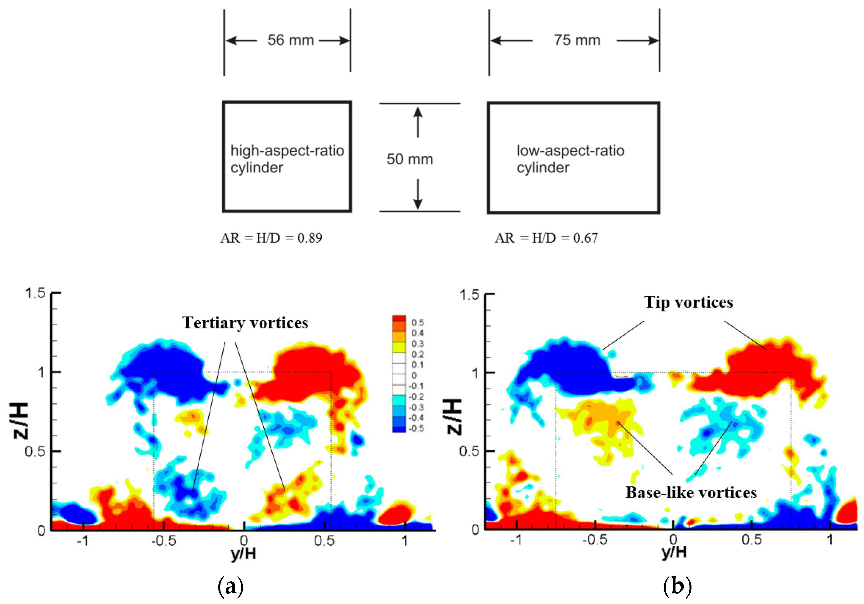
Figure 1. Isocontours of dimensionless, time-averaged streamwise vorticity, ωx* = ωxH/U, in the wake of circular cylinders (H = 50 mm) [9] in x/H = 1.0. (a) AR = 0.89 and (b) AR = 0.67. Red shades represent positive counter-clockwise vorticity, blue shades represent negative clockwise rotation.
Fluids 08 00032 g001
Figure 2. (a) Side view of DPIV experimental-setup and cylinder cross-sections. Laser position is for transverse (y – z) planes (upstream images) illumination. (b) Location of the some DPIV measurement planes. (c) Plan view of hot-film probe positions. The probe was positioned in y/D = ±1 and 1 ≤ x/D ≤ 3. Dotted line square shows the projection of the top access window on the base plate.
Fluids 08 00032 g002aFluids 08 00032 g002b
Figure 3. Mean streamlines downstream of the cylinders (H = D = 50 mm): (a) cube; (b) cylinder.
Fluids 08 00032 g003
Figure 4. Dimensionless, time-averaged, streamwise vorticity, ωx* = ω x H / U , in the wake of cube in x/D = x/H = 0, 0.5, 1.0, 1.5, 2.0, and 3.0. Red shades represent positive counter-clockwise vorticity, blue shades represent negative clockwise rotation.
Fluids 08 00032 g004
Figure 5. Dimensionless, time-averaged, streamwise vorticity, ωx*, in the wake of cylinder in x/D = x/H = 0, 0.5, 1.0, 1.5, 2.0, and 3.0. Red shades represent positive counter-clockwise vorticity, blue shades represent negative clockwise rotation.
Fluids 08 00032 g005aFluids 08 00032 g005b
Figure 6. The power-spectral-density function of the streamwise velocity at x/H = 1 and y/H = 1 for: (a) cube, (b) cylinder. Each spectrum is the average of 20 individual spectra. Spectra are offset by constant factor for clarity.
Fluids 08 00032 g006
Figure 7. Auto- and cross-correlation-coefficients for fluctuating velocity on opposite sides of the cube at x/H = 1 and y/H = ±1 and 0.25 ≤ z/H ≤ 1.
Fluids 08 00032 g007
Figure 8. Naming convention of the main vortex structures identified in the cylinder wake.
Fluids 08 00032 g008
Figure 9. Naming convention of the main vortex structures identified in the cube wake.
Fluids 08 00032 g009
Disclaimer/Publisher’s Note: The statements, opinions and data contained in all publications are solely those of the individual author(s) and contributor(s) and not of MDPI and/or the editor(s). MDPI and/or the editor(s) disclaim responsibility for any injury to people or property resulting from any ideas, methods, instructions or products referred to in the content.