Abstract
This research conducts a numerical study of a wave energy converter (WEC) device with five coupled hydropneumatic chambers, operating based on the principle of an oscillating water column (OWC). A turbine was not included, only considering the tube without it. The computational domain was defined by a wave channel housing an OWC device subjected to regular incident waves. The central objective was to assess the impact of chamber geometry on maximizing the total hydropneumatic power in energy conversion. The numerical simulations consider the pressure, mass flow rate, and total hydropneumatic power, with the latter being the performance indicator. To determine the geometries to be analyzed, the Constructal Design method was employed in conjunction with the exhaustive search optimization method to maximize the performance indicator. The degrees of freedom defined were the ratios between the height (Hn) and the length (Ln) of the hydropneumatic chambers (Hn/Ln, where n varies from one to five). Based on the results of the mass flow rate and pressure, their influence on power was evaluated. It was observed that the influence of the degrees of freedom on the pressure difference, mass flow rate, and hydrodynamic power was quite similar, displaying an increase for low ratios of Hn/Ln up to a maximum magnitude and followed by a decrease in magnitude. The best performance was achieved for the geometric configuration with Hn/Ln = 0.2613 (Hn = 5.0625 m and Ln = 15.8219 m), representing an improvement of 98.6% compared to the worst case analyzed.
1. Introduction
The ocean presents itself as a significant concentration of renewable energy. According to the International Energy Agency (IEA), ocean energy can currently be exploited using five different technologies: (i) high and low tides, (ii) marine/ocean currents, (iii) waves, (iv) temperature gradients, and (v) salinity gradients [1].
Wave energy is a renewable, inexhaustible source and a native resource; the success of wave energy converter (WEC) installations is directly linked to research and development in this field, as well as to the study of implications for the marine ecosystem [2,3]. WECs can be categorized in various ways, including by their installation location, size, wave direction characteristics, and operating principle [4].
One of the standout WEC devices is the oscillating water column (OWC). Its operating principle consists of a hollow chamber partially submerged in which the action of external waves excites the oscillation of the internal water column. This oscillating water column pressurizes the air in the top part of the chamber, inducing airflow through a duct that drives bidirectional airflow over the turbine [5].
With the characteristic of reducing the cross-sectional area, as the fluid (air) passes from the hydropneumatic chamber to the turbine duct, the air velocity increases, and, consequently, the energy conversion also increases [6]. An important feature is that such devices have no direct contact of the turbine and generator with water, increasing their durability [7].
Projects involving the study of OWCs can be categorized into two aspects: numerical and experimental. The choice of these methodologies depends on the researcher’s approach to the work, but some OWC-WEC studies use one of the mentioned methodologies or even both in the same investigation. Additionally, some studies employ the Constructal Design method for the geometric evaluation of devices, focusing on examining the geometry of hydropneumatic chambers.
The classification of OWC devices is also an important factor for the delineation of research conducted; one possibility for classification concerns the depth at which they are installed. Work concentration in the area of an OWC is limited to devices on the coast or nearby, even with wave energy loss due to the shallower water depth. However, the study of offshore devices is of interest as they exhibit higher power per wave front meter due to the greater depth of the device compared to the seabed [4].
State of the Art
For a better understanding of the reader, the state of the art has been divided into (i) experimental works; (ii) numerical works without the use of the Constructal Design method; and (iii) numerical works with the use of the Constructal Design method. The presentation of the research, the summary of it, and the contribution to the present work will be given in the same order as already mentioned.
Experimental works are the basis for numerical works; one can cite the research developed by Ning et al. [8], who conducted an experimental investigation on the hydrodynamic performance of an onshore OWC device equipped with two hydropneumatic chambers. Their objective was to evaluate both the overall performance and the individual performance of the two sub-chambers in the system. The study revealed that both the maximum efficiency and the wave frequency range improve wave energy absorption in an OWC system with dual chambers compared to a standard single-chamber OWC device. This work is relevant because it presents an experimental application of a project very similar to what was studied in the research developed in this article.
The study of multiple coupled chambers experimentally serves as a starting point for numerical studies, as it is possible to numerically evaluate points that are not as well understood with experimental studies. Kim et al. [9] conducted a study on an OWC device with multiple experimental chambers, focusing on its hydrodynamic performance and energy conversion properties. They analyzed devices with single, triple, and asymmetric triple chambers in a wave tank. The results revealed that the triple-chamber OWC led to enhanced hydropneumatic energy conversion compared to the single-chamber OWC, which was mainly attributed to the reduction in the internal fluid motion, leading to the study of devices with more coupled chambers and the influence of adding chambers to OWC devices.
For the execution of numerical works, it is necessary to validate and verify the numerical model to be used. Thus, the work of Maciel et al. [10] presented a numerical investigation of an OWC device, during which they verified and validated a methodology for numerically generating waves using transient discrete data as a prescribed velocity boundary condition. Although there was a small discrepancy in the results obtained when using discrete data as a velocity boundary condition, they generally aligned with the results of laboratory experiments.
A numerical study of devices with two coupled chambers was developed by Yu et al. [11], who presented a work investigating the hydrodynamic performance and efficiency of an OWC device with two coupled hydropneumatic chambers under different combinations of damping and width. The results indicate that an OWC with variable opening ratios is more efficient and offers benefits by adjusting to floating wave conditions compared to an OWC composed of two chambers with identical orifice dimensions. This work does not yet present the possibility of multiple coupled chambers but defines parameters to assist future work in the area.
Studies on the design of chambers have been developing possibilities for better energy conversion. The research on coupled chambers by Li et al. [12] introduced a new design for OWC devices. The proposed device includes a floating body and two extended vertical tubes open at the bottom, creating dual chambers at the top. The findings of the study indicate that increasing the draft, which has a positive correlation with the total mass of the CEO model, improves the ideal response period. Furthermore, it was observed that the CEO model with a flat bottom demonstrates superior energy capture performance. This work, together with others, led to the possibility of thinking about OWC devices with more coupled chambers and how their geometry influences the converted power.
Additionally, the use of Constructal Design for the evaluation of the geometric configurations of CEO devices, particularly in the case of OWC devices, has been steadily increasing. Constructal Design is based on the Constructal Law, which initially served as a design tool to improve the performance of engineering systems or represent a natural phenomenon. Consequently, the Constructal Law deals with the transformations experienced by any flow system [13]. The geometry of the structures needs to be altered to maximize usage while minimizing energy consumption [14].
Focusing on the application of Constructal Design to OWC CEO, the following studies employed the exhaustive search optimization method to evaluate all suggested geometric configurations and determine the one that provides superior performance. Additionally, a two-dimensional approach was employed using the finite volume method (FVM) and the volume of fluid (VOF) technique to address water–air interactions in multiphase problems with regular waves as a computational model.
A study of coupled chambers was conducted by Lima et al. [15]. In this work, an OWC device with four coupled chambers was presented, with its degree of freedom being the Hn/Ln ratio (the ratio of the height to length of coupled hydropneumatic chambers). The results show that there is a maximum hydropneumatic power, with this value used as a reference for the analyzed configuration and geometric arrangement. This work, together with others, opened up space for the discussion of adding coupled chambers and device design and their influence on hydropneumatic power gain.
The study of OWC devices’ inlets proves to be important, along with the study of their geometry, forming a set of theoretical references for the formulation of future works. Letzow et al. [16] numerically investigated the influence of geometry on a full-scale OWC device with a seabed ramp. The study involved three degrees of freedom, and the globally optimized geometry resulted in twice the maximized available power, 37.3% greater than in the best case without the seabed ramp below the chamber and 7 times better than in the worst case.
Finally, Lima et al. [17] conducted a study to assess the increase in coupled chambers and their influence on the accumulated hydropneumatic power. In total, devices containing from one to five coupled chambers were evaluated, and it was observed that devices with five coupled chambers exhibit higher accumulated power values than others, even with a decrease in hydropneumatic power in chambers farther from the initial wave structure interaction.
Therefore, the present work is conducted numerically and aims to specifically analyze the geometric variation of an offshore OWC device with five coupled chambers, detailing each parameter and its variations with different geometric configurations. It is a specific analysis of this configuration, differentiating itself from previous works.
Constructal Design [18] is used through the investigation of chamber shapes, where they are varied by changing the degree of freedom Hn/Ln (the ratio between the height and length of coupled hydropneumatic chambers), where n varies depending on the number of chambers, in this case, n = 1, …, 5. Due to its numerical nature, certain simplifications are taken into account, including a two-dimensional, transient, and incompressible multiphase flow.
Numerical solutions are employed to solve the equations of mass and momentum conservation and an equation governing the transport of the volumetric fraction of water. These calculations are performed using the finite volume method (FVM) [19,20], and the interaction between water and air is addressed using the volume of fluid (VOF) model [21,22].
The studies conducted in this research are original and complement the research developed in [17], presenting an analysis of the influence of coupling five hydropneumatic chambers in an OWC device and how this coupling affects the available power in the system, thereby contributing to the state of the art.
2. Mathematical Modeling
Ocean waves are generated by the action of the wind or disturbances on its surface, in addition to landslides, earthquakes, and the gravitational attraction of the sun and moon [23]. Different parameters can define the characteristics of a regular wave. These characteristics can be seen in [17,24].
For the accurate representation of waves in computational works, the choice of the appropriate wave theory is crucial. A resource commonly employed is presented by Dean and Dalrymple [24], who provide a diagram based on the parameters h (depth), H (wave height), and T (period). Through these parameters, it is possible to determine dimensionless quantities that, when applied in the proposed diagram, allow one to verify that the study fits within the characteristics of regular waves of the Stokes Second Order type.
The free surface elevation (η) represents the free surface’s position relative to the MWL [24], and it is defined as follows:
The parameters present in Equation (1) are as follows: A is the wave amplitude (m), x is the coordinate representing the main direction (m), t is the time (s), ω is the frequency (rad/s), k is the wave number (m−1), and h is the depth (m).
2.1. Description of Wave Characterization
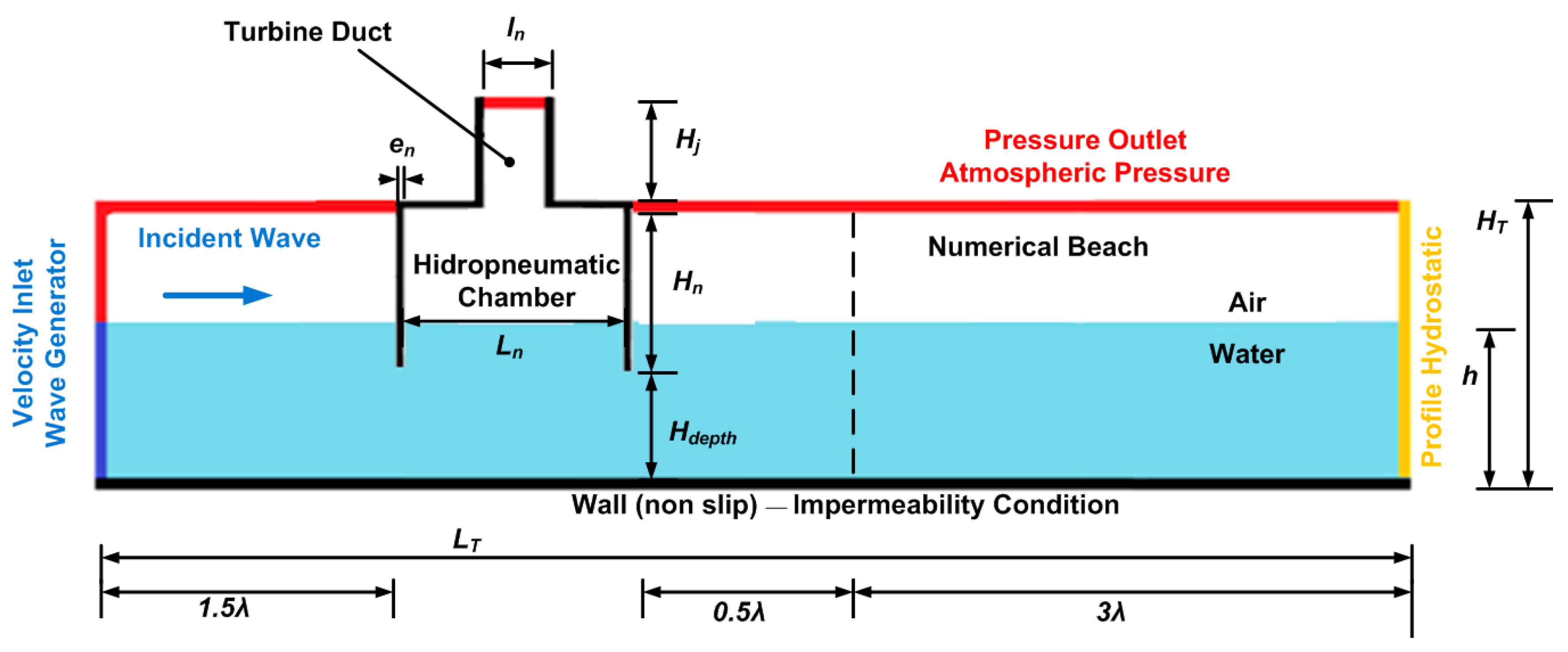
The work developed was performed numerically but using real-scale relationships. Figure 1 presents the two-dimensional schematic model of the numerical wave channel with only one chamber, simplifying the model studied in the investigation. Its dimensions depend directly on the characteristics of the waves adopted in the proposed problem, which are considered on a real scale.

Figure 1.
Visualization of the 2D computational model comprising the wave channel and the OWC device. (Adapted from Lima et al. [17]).
Care must be taken so that the water in the wave channel does not occupy space outside the computational domain. To achieve this, one needs to consider both the water depth (h) and wave height (H). As per the research conducted by Gomes et al. [25], it is feasible to establish a minimum wave channel height described by the expression h + 3H.
All dimensions of the wave channel can be seen in Table 1. The values for the chosen wave climate were based on the conditions presented by Pianca et al. [26] and Espindola et al. [27] in their works. Along the southern coast of Brazil, the wave height and period vary throughout the seasons within the range of 1.0 m ≤ H ≤ 3.0 m and 5.0 s ≤ T ≤ 12.0 s at offshore positions. Other studies also utilize this same sea state, as seen in the works conducted by Gomes et al. [25,28] and Letzow et al. [16].

Table 1.
Characteristics of the wave and wave channel.
The depth of wave propagation equals that of the wave channel. When determining the channel’s length, it is essential to take the wave length into account. These dimensions are recommended and presented by Lima et al. [17].
Additional features are required to delineate the two-dimensional geometry of the OWC device, encompassing the heights of the hydropneumatic chambers (Hn), the submersion depth of the device (Hdepth), the elevations of the turbine ducts (Hj), the lengths of the ducts (lj), the lengths of the chambers (Ln), and the thicknesses of the columns dividing the devices (en). Here, the variable n ranges from one to five, while j ranges from 7 to 11.
2.2. Formulation of Pressure and Mass Flow Rate Using the RMS Methodology
The specific objective of this investigation is to assess the influence of geometric variation on the maximization of hydropneumatic power in multi-chamber OWC devices. Since the performance indicator depends directly on the pressure and mass flow rate, the study of changes in these two quantities is also observed throughout the obtained results. The RMS (root mean square) methodology was used to obtain average values.
The water-free surface elevation is monitored using the following integral [29]:
where αwater is the amount of water in each volume, and At is the area of each volume (m2). The monitoring of the mass flow rate at the center of each turbine duct is conducted through the following integral [29]:
where represents the velocity in the z direction (m/s); ρair is the density of the air (kg/m3). The mean values were calculated using the arithmetic mean for transient RMS problems [17]:
where n represents the quantity to be calculated on the average RMS. For further details on Equations (2)–(4), it is recommended to consult Marjani et al. [30].
The available hydropneumatic power is calculated according to [31]:
where Pair is the static pressure in the turbine duct of the OWC device (Pa), is the mass flow rate through the turbine duct (kg/s), and vair is the velocity of the air in the turbine duct (m/s); the other parameters can be found in Gomes et al. [28] and Lima et al. [32].
2.3. Constructal Design Applied to OWC–WEC
The attainment of geometries for OWC devices that optimize wave energy extraction is achieved through the use of Constructal Design, a method employed to apply the Constructal Law. In accordance with the Constructal Design method [18], the constraints of the problem include the volume of hydropneumatic chambers (VEn), total volumes (VTn), and device column thicknesses (en), where n ranges from one to five, representing the number of interconnected chambers.
Some geometric recommendations follow what was presented by Lima et al. [15], such as the thickness (en) of 0.1 m. Since it is a problem in which all hydropneumatic chambers exhibit geometric similarity, it is possible to generalize their formulation; the sub-indices follow the definition already presented in this text. The dimension W in Equations (6) and (7) is kept constant and equal to 1 m because it is a two-dimensional computational model.
The analyzed degrees of freedom in this work are the ratios between the height and width of the hydropneumatic chambers (Hn/Ln). Using Equations (6) and (7), it is possible to determine the equations that define the lengths (Ln) and the heights (Hn) of the problem:
To determine the initial values of the inlet volume and total volume, the following recommendations are followed: represents 70% of , using values of = 93.4 m3 and = 65.4 m3. These values for the entrance and total volumes are presented by Gomes et al. [28], who studied the geometric recommendations of OWC devices by means of Constructal Design.
The use of the Constructal Design method in the present work lies in determining geometric constraints, enabling the derivation of dimensionless formulations of the degrees of freedom so that a numerical method can be applied. It was also utilized to perform the analysis of the variation in selected geometries. The numerical methods used in the present work are presented in the following section.
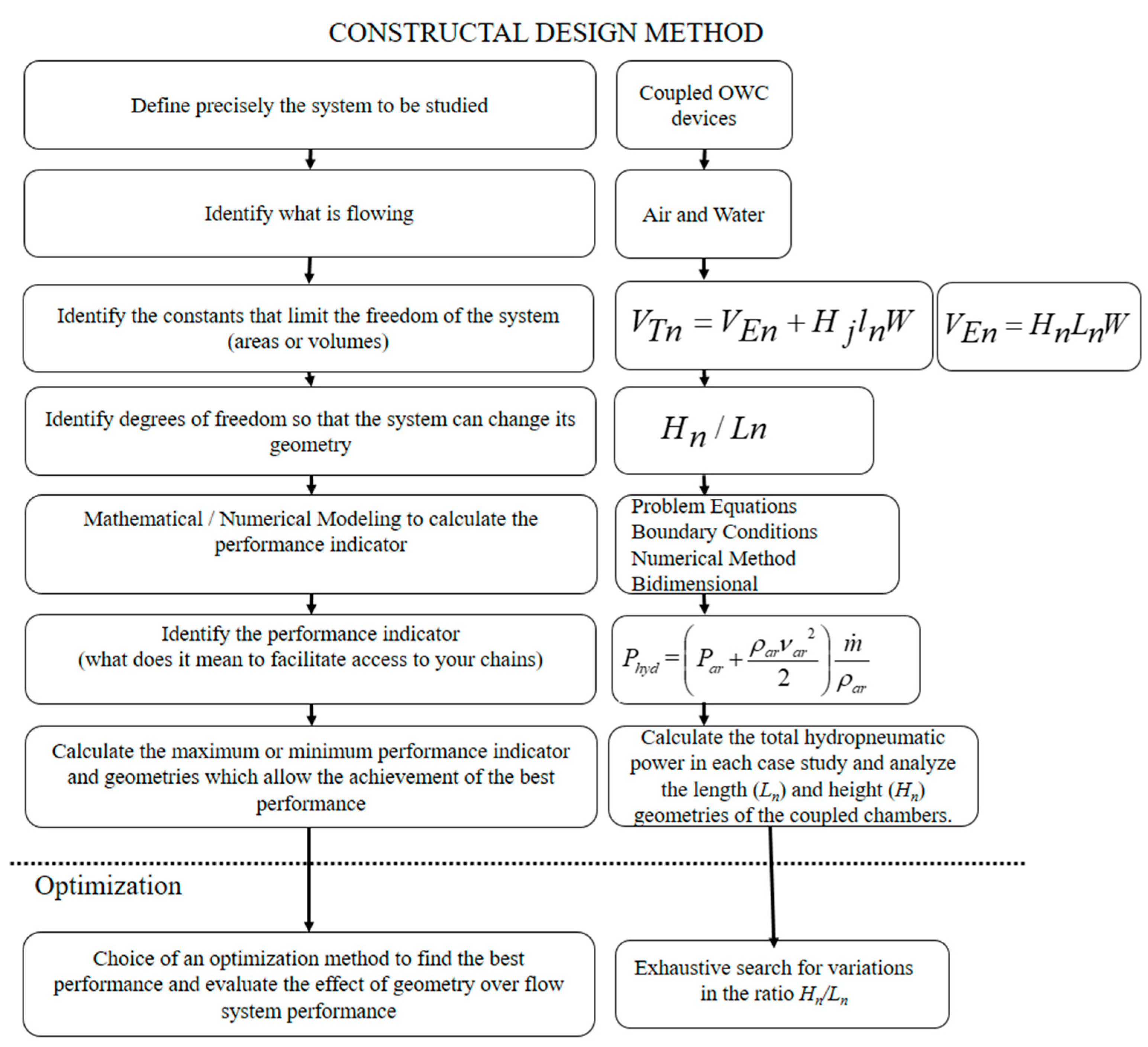
For a better understanding of the execution steps of the Constructal Design method, Figure 2 presents the detailed scheme. Figure 3 illustrates all the cases studied with the analyzed degrees of freedom and the values used. All analyzed geometries are presented in Table A1, Table A2 and Table A3 in Appendix A.
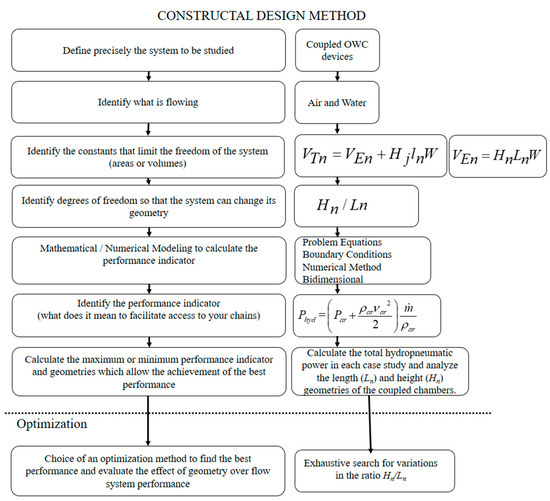
Figure 2.
Execution steps of the Constructal Design method.
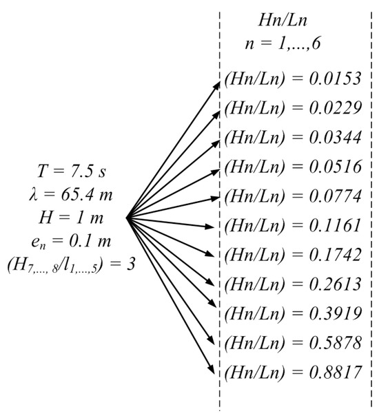
Figure 3.
Representation of the analyzed cases and the value used for the degrees of freedom.
3. Computational Modeling
This study presents a two-dimensional computational domain with an OWC device comprising five chambers. There is no reduction or addition of chambers, and the device is inserted into a wave channel. This configuration enables the numerical simulation of the structure’s interaction with waves generated numerically, thereby replicating real-scale sea conditions. The volume of the hydropneumatic chambers was kept constant in all cases analyzed in the numerical simulations.
For the numerical solution of the conservation equations for mass, momentum, and volumetric fraction, the FVM was used [33,34]. The numerical simulation of the analyzed cases was carried out using the CFD Fluent™ 14th edition commercial package. The numerical parameters adopted in the ANSYS Fluent 14th edition commercial software are presented in Table 2 [34].
Table 2.
Methods adopted in numerical simulations.
3.1. The Multiphase Model
As the present study involves numerical analysis, the research methodology relied on Computational Fluid Dynamics (CFD). This approach deals differentially with the conservation equations of mass and momentum, employing a system of algebraic equations that can be computationally solved [33,34].
This research presents a study involving two fluids, water and air, characterizing a multiphase problem, in which the recommended numerical modeling is called volume of fluid (VOF), which performs surface tracking. In the proposed problem involving two fluids, it is essential to introduce the concept of volume fraction (α) to represent the phases within each control volume. Here, α is a continuous variable both in space and time, signifying the presence of fluid within the control volume [35].
Therefore, Fox et al. [36] present the model formulation, which includes the equation for the conservation of mass in two phases.
the volume fraction equation is given by
and the momentum equation for the water–air mixture is solved in the computational domain and given by
where is the density of the fluid (kg/m3), t is the time (s), is the flow velocity vector (m/s), p is the static pressure (Pa), is the viscosity (kg/m·s), is the tension tensor, and is the acceleration of gravity (m/s2).
The VOF method does not explicitly calculate the position of the free surface between fluids. Consequently, it becomes essential to discretize the volume fraction within the interface region between the two fluids. Hence, cells with αwater ranging from 0 to 1 encompass the interface between water and air (αair = 1 − αwater). Cells with αwater = 0 are entirely filled with air (αair = 1), while, conversely, those with αair = 0 are entirely filled with water.
The physical properties of the region between the two fluids are determined as weighted averages using the volumetric fraction. Consequently, density and viscosity are expressed as detailed in [37]. The properties of the fluids involved in this work can be found in [38]:
For the numerical solution of the mass (Equation (12)) and momentum conservation (Equation (14)) equations, a commercial code based on the FVM was used. The primary advantage of this method is that spatial discretization occurs directly in physical space, eliminating issues associated with coordinate system transformations, as observed in the finite difference method (FDM) [39].
Thus, the VOF methodology made it possible to obtain results for the power indicator of the proposed problem regarding the presence of the two fluids, which is different from what other authors have presented, as they only analyze either the water phase or the air phase; Table 3 presents a scheme of the multiphase method used in the present work.
Table 3.
Scheme of the multiphase model.
3.2. Numerical Wave Generation and Boundary Conditions
The numerical wave employed in this study was generated using the methodology available in the Fluent 14th edition software. The chosen wave theory (for this investigation, it was Second Order Stokes) and parameters such as height and wave length were specified through the VOF methodology, defined as the open channel wave boundary condition [39]. The numerical wave generator was situated to the left of the wave tank, as highlighted in blue in Figure 1.
It is necessary to divide the prescribed velocity into horizontal and vertical components, respectively, described as a boundary condition [40]:
The other boundary conditions present in the problem can be observed in Figure 1. The initial condition of the problem considers a fluid at rest (flat condition), with depth h = 10 m and t = 0 s in the free surface elevation equation (Equation (1)). To reduce the effects of wave reflection and thus maintain results closer to real sea conditions, a numerical beach region was inserted into the channel, and a sink term (S) was added to the momentum conservation equation, recommended by [28,39,41], as follows:
where C1 and C2 are the linear and quadratic damping coefficients, respectively, the term (kg/m3) refers to density, (m/s) is the velocity, z (m) is the vertical position, zfs (m) and zb (m) are the vertical positions of the top and the bottom, x (m) is the horizontal position, and xs (m) and xe (m) are the horizontal positions of the beginning and finish of the numerical beach. More details about the studies related to the linear and quadratic terms in the equations can be found in [29,42].
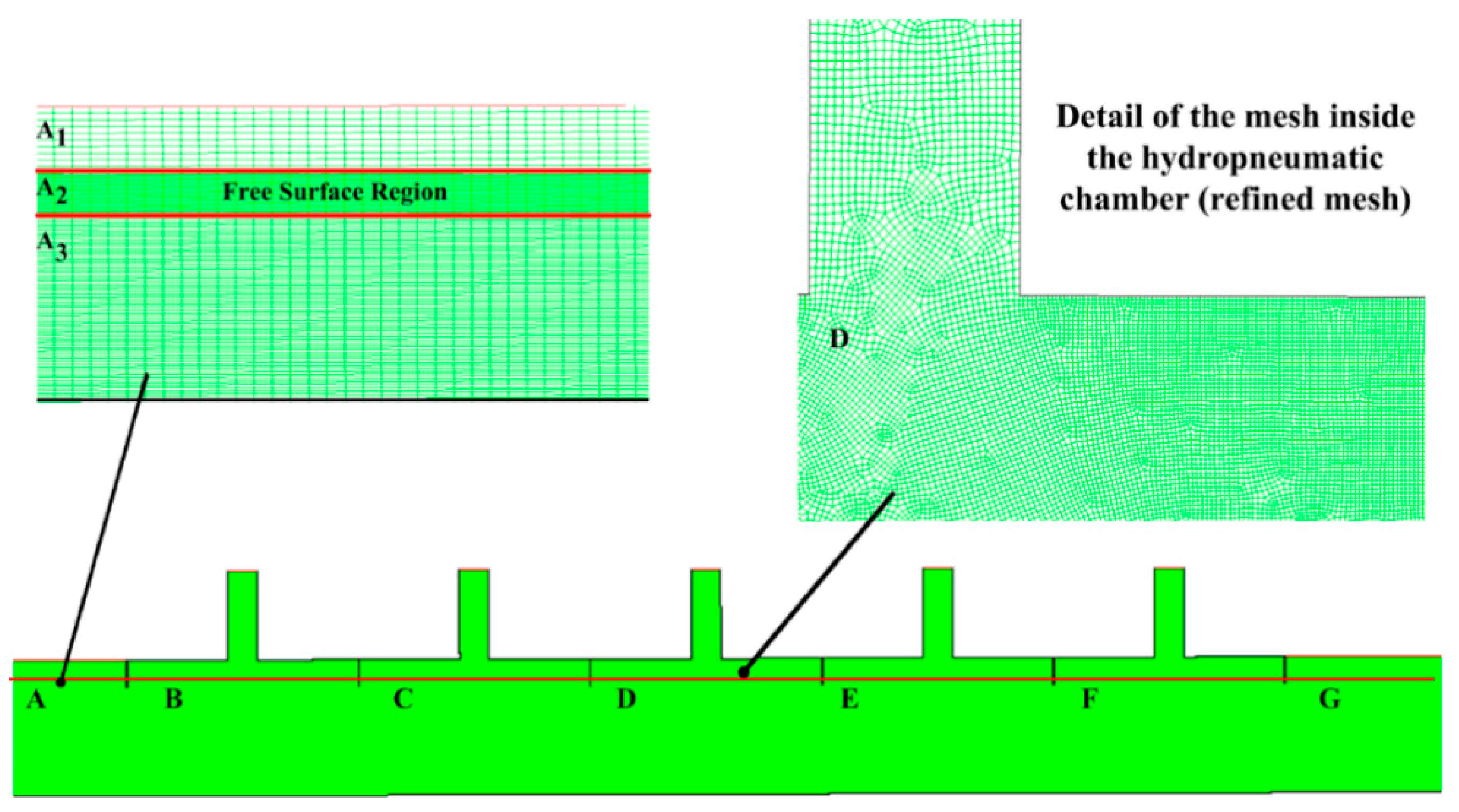
3.3. Mesh Study
The computational domain was discretized using rectangular volumes with the finite volume technique. All numerical meshes generated in this research used the stretched methodology, developed by Mavripilis [43] and employed in other works by researchers such as Gomes et al. [28], Letzow et al. [16], and Lima et al. [17]. Mesh quality tests were also conducted by the researchers and can be consulted in their works, as well as in Table 4, with the mesh quality test referring to the current study, and with case 2 being chosen.
Table 4.
Results of the mesh quality study.
The stretched methodology consists of defining regions that are more refined than others. These regions are defined by the interest of the investigation, which in the present work is the free surface region and the interiors of the hydropneumatic chambers. Figure 4 presents the bidimensional computational mesh of the studied problem and its divisions.
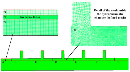
Figure 4.
Numerical bidimensional mesh of the computational domain.
To streamline the modeling of the computational domain, it was partitioned into three regions with distinct subdivisions (refer to Figure 4): for wave verification before the device, Region A was further divided into three sub-regions (A1, A2, and A3) with varying refinements, in accordance with the stretched methodology. Region A2 underwent a more intricate refinement due to its involvement with the free water surface, entailing 40 volumes in the vertical direction and 120 volumes horizontally. Conversely, for Regions A1 and A3, where the extracted values did not directly impact the performance indicator, 30 and 110 volumes in the vertical direction, respectively, were utilized, following the recommendations of Barreiro [44].
In the internal regions of the hydropneumatic chambers, detailed in Figure 4, greater refinement of the mesh can be observed to ensure greater precision of the results, following the recommendation of mesh construction according to the stretching methodology. The region after the OWC devices has 200 horizontal volumes and the same vertical discretization as Region A.
Due to the computational domain employed in this research and following theoretical recommendations, spatial discretization was built with squares of 0.1 m per side, totaling 620 horizontal control volumes for the more refined region, while squares of 1 m were used for the regions outside the devices. This choice was based on the recommendations presented by Gomes et al. [28].
3.4. Evaluation of the Numerical Model
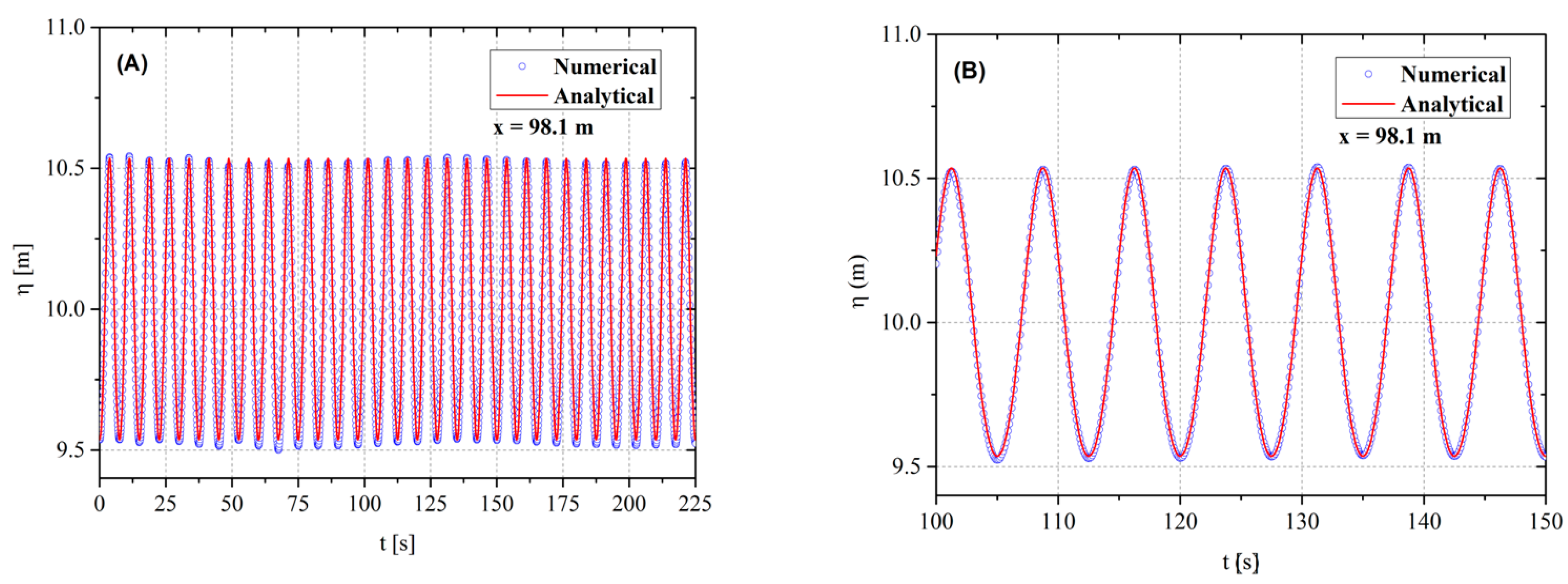
The evaluation of the numerical model used in works in this line of research was necessary for verification and validation, that is, to observe if the model used is in accordance with the theoretical equations and experimental results already performed. One way to analyze wave energy problems is to compare the transient elevation of the numerical free surface with the respective analytical solution presented in Equation (1), maintaining the same position. This procedure is called verification.
Figure 5 compares these results in a two-dimensional wave channel without the OWC device. The measuring probes were placed at position x = 98.1 m. The total simulation time was 225 s. Thus, the mean difference between the numerical and analytical results was 1.39%, with a maximum value of 3.54%. The accuracy of the result makes the chosen model suitable for simulating the OWC device.
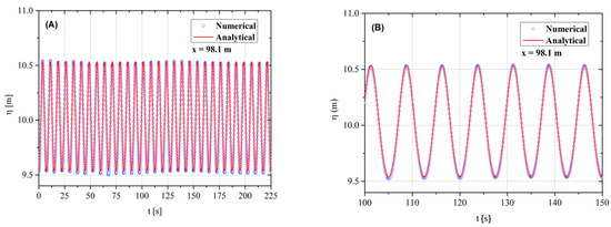
Figure 5.
Comparison of the free water surface elevation for numerical and experimental results: (A) all simulation times; (B) detail of 100 s ≤ t ≤ 150 s.
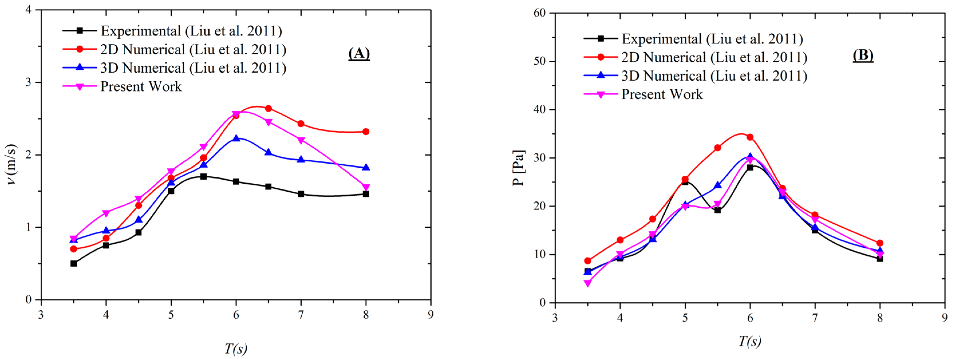
Validation of the numerical model was also necessary. Figure 6 presents it, where the comparison of the present work with the experimental results obtained by Liu et al. [45] can be observed. The validation construction was based on the work developed by Letzow et al. [16] and Gomes et al. [25].

Figure 6.
Comparison among the results obtained in the present study and those presented by Liu et al. [45] for different wave periods.
The obtained results do not show total convergence with the results of Liu et al. [45], but they do exhibit similar trends for the numerical and experimental results. The difference can be explained by the resonance effects between the waves and the chambers.
Despite the difference between the results, it is also possible to observe that as the period (T) of the waves increases, the relative pressure also increases, following the same trend as the experimental results. One point to consider is that the mathematical and numerical model used considers the flow in a laminar and incompressible regime, these being some of the simplifications adopted in the construction of the simulation.
Thus, with the observations made, it is possible to understand the close trend of the numerical and experimental results when compared. The computational model used in the present work can be considered validated, since its verification and validation results have been presented and are consistent with the literature.
4. Results and Discussion
The presented results take into account the formulation of hydropneumatic power as already outlined in Equation (5), which considers pressure and mass flow formulations. In total, eleven geometric configurations proposed by the Constructal Design method were analyzed; this choice was assisted by the exhaustive search optimization method.
In addition to determining the optimal geometry, it was also possible to assess how the degree of freedom influences the behavior of the performance indicator and parameters such as the mass flow rate and pressure drop in the devices, allowing us to go beyond a simple geometric optimization study. It is worth noting that the computational effort is high, preventing a high number of simulations. Despite that, the cases selected in the present work allowed us to perform the investigation on how the H/L ratio of the coupled chambers influenced the behavior and performance of the OWC, which has been less explored in the literature.
The relationships between the height and length of the hydropneumatic chambers were also analyzed, keeping their inlet volume constant. The other geometric measurements present in the coupled devices can be obtained using the work of Lima et al. [17].
The results for each hydropneumatic chamber were analyzed individually. The sum of the individual performances of each coupled chamber was used to compose the overall performance of the device.
The relationship between free surface elevation, pressure, and hydropneumatic power was established through the implementation of probes for calculating elevation inside the hydropneumatic chambers, making it possible to measure the variation in wave height and water rest position (10 m). This allowed us to determine the air velocity inside the chambers, which is a component of the pressure calculation and, consequently, of the available power.
4.1. Results for Pressure and Mass Flow Rate
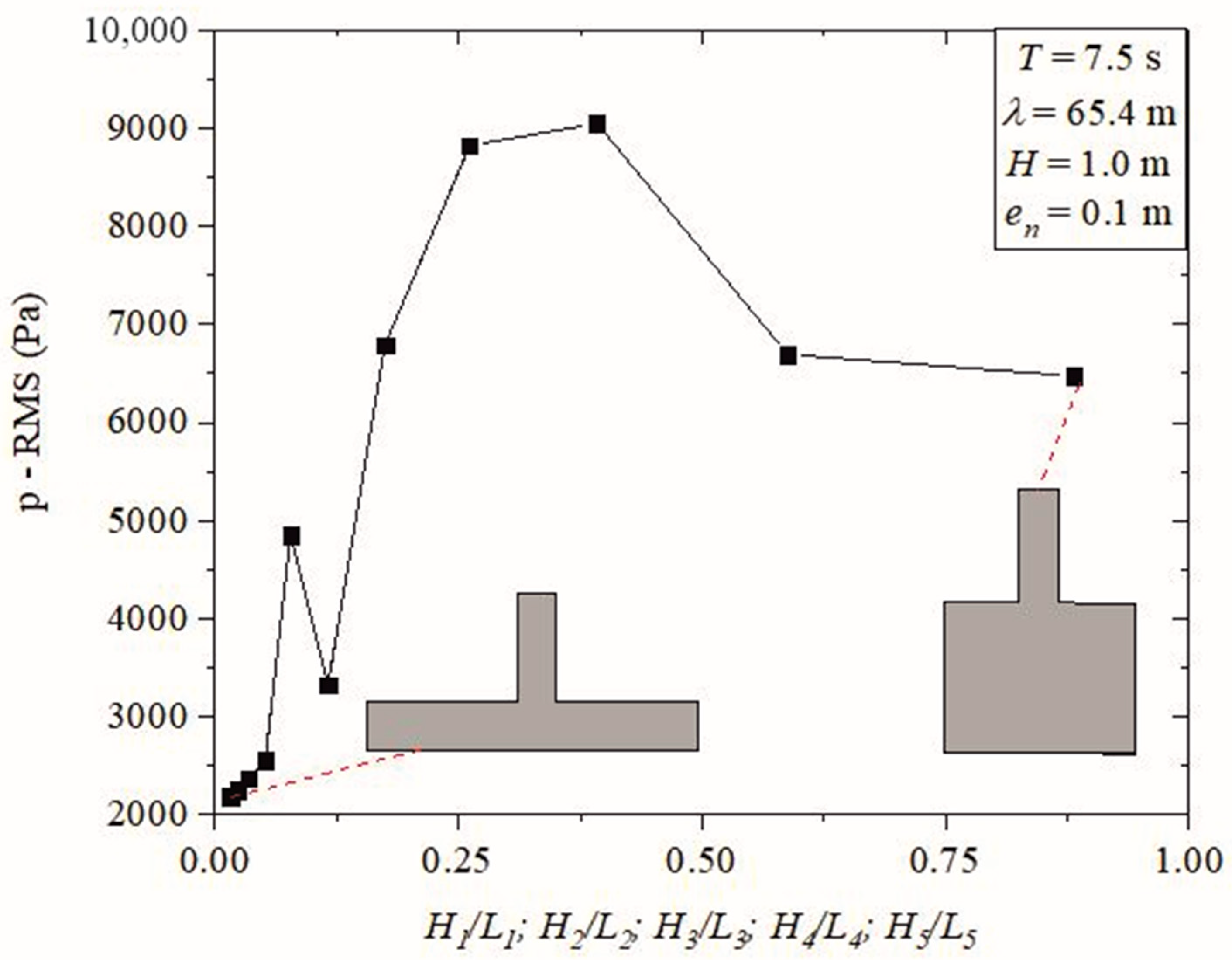
Figure 7 presents the RMS pressure values for the analyzed device as the degrees of freedom vary. An increase in pressure is observed as the chamber width decreases. Some oscillations are noted, but they can be attributed to the compression and decompression process of the air inside the chambers, as well as the effects of wave reflection on their internal walls.
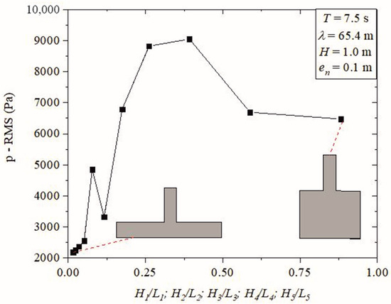
Figure 7.
Accumulated root mean square pressure in coupled device as function of height/length of OWC chambers.
The simulation of the piston movement of the water column inside the device caused the compression and decompression of the air inside the chamber; this shows an increase in the internal pressure in all the coupled chambers, directly influencing the hydropneumatic power. Furthermore, it is possible to observe how the geometry occurs in cases with a smaller and larger Hn/Ln ratio.
With the variation in the degrees of freedom, pressure increases occurred again, which can be explained by the more discontinuous oscillatory movement resulting from the reflection of waves throughout the chambers, which consequently increased the pressure inside them. The case with the highest pressure value, p = 9049.54 Pa, occurred with a degree of freedom equal to Hn/Ln = 0.3919, i.e., Hn = 5.063 m and Ln = 12.918 m.
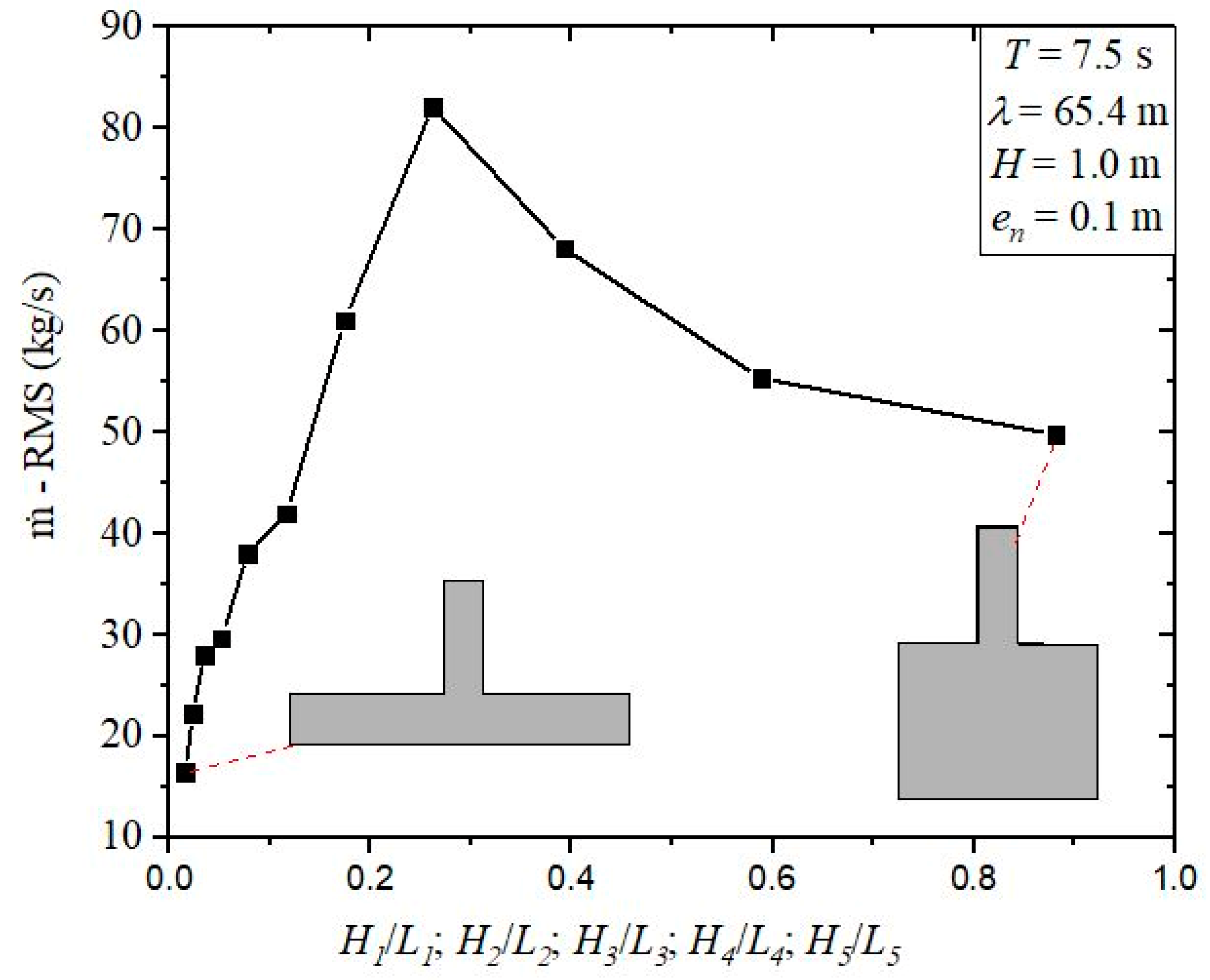
The mass flow rate is another element in the calculation of the device’s hydropneumatic power equation. Figure 8 shows the total mass flow rate behavior for the coupled device.
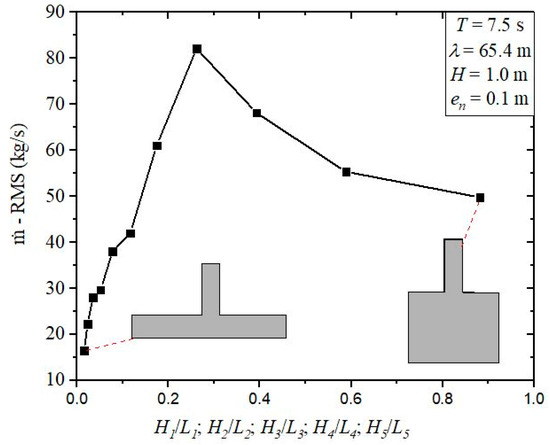
Figure 8.
Accumulated root mean square mass flow rate in each coupled device as a function of the height/length ratios of the OWC chambers.
One can note a similar behavioral trend to that observed for the pressure variation (see Figure 7). Due to the geometric variation, it was possible to identify a decrease in the total mass flow rate after an absolute maximum point. The increase in the height of the hydropneumatic chambers can explain this.
Thus, unlike pressure, the highest performance case was determined to be Hn/Ln = 0.2613, with Hn = 4.1335 m and Ln = 15.8219 m. Furthermore, with an increase in the ratio—meaning an increase in chamber height and a decrease in chamber length—there was a reduction in the mass flow rate values. This trend is explained by the length of the duct housing the turbine of the device, which remained constant, as the mass flow rate tends to decrease even under high pressure.
4.2. Results for Hydropneumatic Power
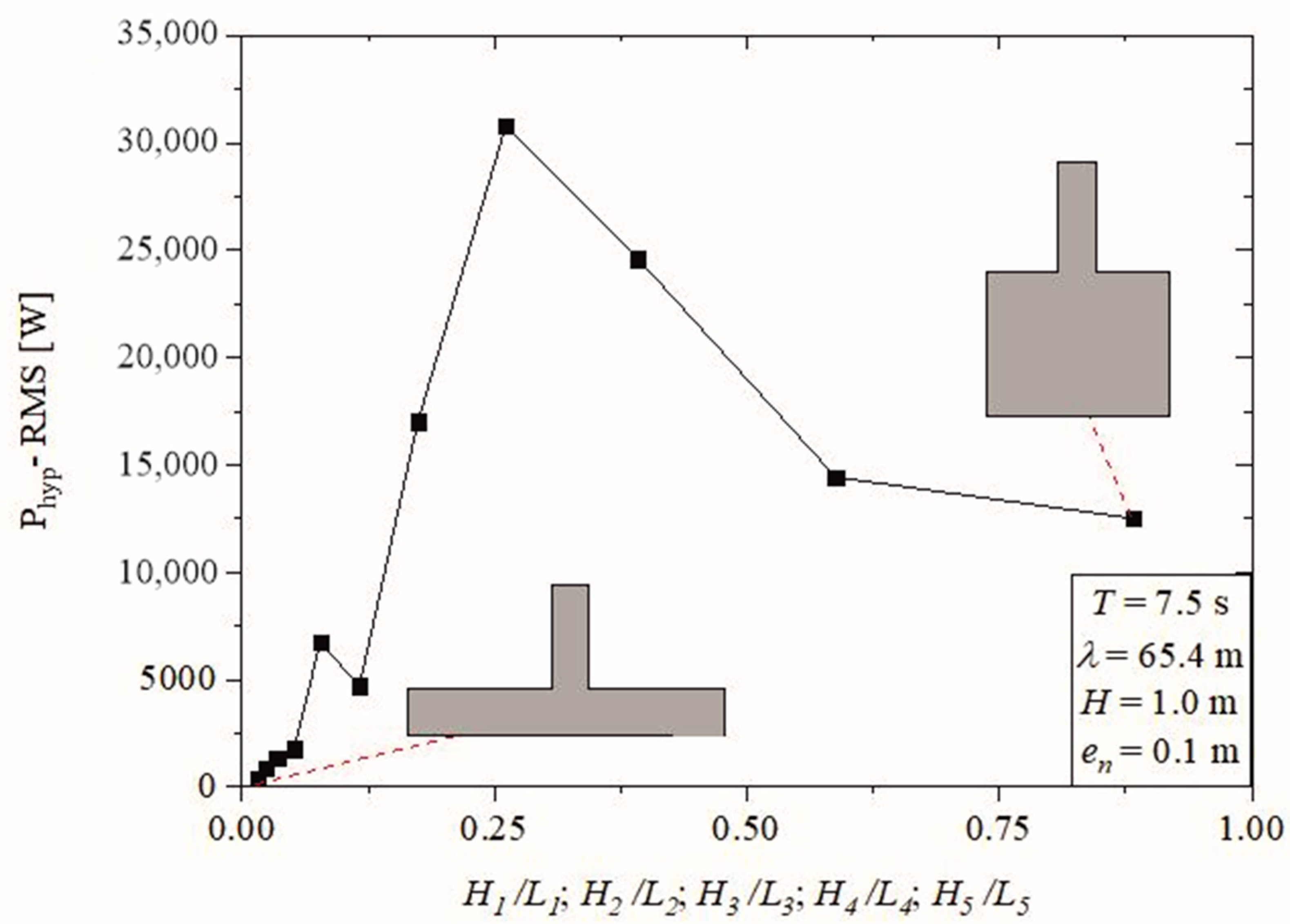
In turn, the hydropneumatic power represents an association of the results obtained with the accumulated pressure and mass flow rate, according to Equation (5). As in the previous results, the accumulated power is represented by the sum of the individual powers of each coupled hydropneumatic chamber.
Figure 9 shows the variation in the accumulated hydropneumatic power for all geometries studied. As in the case of pressure (see Figure 7) and mass flow rate (see Figure 8), it is possible to perceive a very similar behavior of the available hydropneumatic power variation as the geometries change by increasing Hn/Ln. The main explanation rests on the effect of compression and decompression of the hydropneumatic chambers and the piston effect that occurs differently with the increase in the height of the chambers and the decrease in their width.
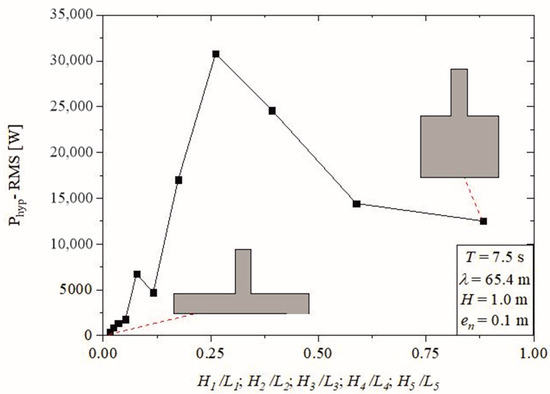
Figure 9.
Accumulated available root mean square hydropneumatic power in each coupled device as function of height/length of OWC chambers.
The gradual increase in the accumulated available hydropneumatic power, with its maximum in the geometry already indicated, can be explained by the increase in pressure due to the area of the turbine duct being fixed and, with the decrease in the area for air passage, there is an increase in pressure that is a factor directly proportional to hydropneumatic power.
The case with the highest performance within the displayed range, with five chambers coupled and geometry with the ratio Hn/Ln = 0.2613 (Hn = 5.0625 m and Ln = 15.8219 m), led to an available hydropneumatic power of (Phyd)opt = 30.8 kW. The lowest performance case had one chamber, and the ratio Hn/Ln = 0.0153 (Hn = 1 m and Ln = 65.4 m) conducted an available hydrodynamic power of (Phyd)opt = 0.4168 kW.
With the obtained results, it is possible to establish a theoretical recommendation for the geometry of hydropneumatic chambers using the height and wave length parameters referenced in the numerical investigation. Thus, it can be recommended that the configuration Hn/Ln achieves maximum energy conversion. This result is a theoretical recommendation for cases with five coupled OWC devices based on the geometry that presented the best performance (Hn/Ln = 0.2613).
Thus, the combination of the Constructal Design method with the exhaustive search optimization approach demonstrated its effectiveness as a tool for analyzing OWC devices with multiple coupled chambers, especially with five chambers, and understanding the impact of design on the device’s performance.
5. Conclusions
The present work presents a numerical study of an OWC device with five coupled chambers. This investigation aims to analyze the influence of geometric variation, keeping the inlet volumes constant, in relation to the total available hydropneumatic power converted by the device.
The research associates computational modeling, Constructal Design, and exhaustive search studies. The first is based on CFD, approaching the equations of conservation of mass and momentum in the differential form through a system of algebraic equations and using the VOF methodology since it involves two fluids (water and air). The exhaustive search method allows one to go through all the determined results and discover the geometric arrangement with the highest performance for a device with five chambers coupled in the search space defined with Constructal Design.
As part of the Constructal Design method, degrees of freedom were defined as H1/L1, H2/L2, H3/L3, H4/L4, and H5/L5. The problem restrictions were defined as the volume of the hydropneumatic chambers (VE1, VE2, VE3, VE4, and VE5), the volume of each hydropneumatic chamber added to the turbine duct volume (VT1, VT2, VT3, VT4, and VT5), and the thickness of the columns that divide the devices, which were kept constant (e1, e2, e3, e4, and e5).
With the variation in the geometries, the results for pressure, mass flow rate, and total available hydropneumatic power, which represent the sum of the objective functions in each hydropneumatic chamber individually, were analyzed. In all studies, it was possible to observe an absolute maximum point that defines a geometry that maximizes the magnitudes studied. For the analyzed performance parameter, it is possible to infer that both the mass flow rate and hydropneumatic power present the same geometry for their cases of greater performance. However, there is a different geometry for the case of maximum pressure, but with a slight variation in the other magnitudes analyzed.
The results show that as the height of the chambers increases and their length decreases, the performance indicators show an increase up to a degree of freedom value. After the absolute maximum point, there is a decreasing behavior of the indicators, tending to their stability. Through this study, it was possible to identify that the highest performance case was found in the geometric configuration Hn/Ln = 0.2613 (Hn = 5.0625 m and Ln = 15.8219 m).
The difference in the available hydropneumatic power for the optimal and worst performance cases was 98.6%. The highest performing case had Hn/Ln = 0.2613 (Hn = 5.0625 m and Ln = 15.8219 m), leading to a hydropneumatic power of (Phyd)opt = 30.8 kW. The lowest performance case had one chamber, and the ratio Hn/Ln = 0.0153 (Hn = 1 m and Ln = 65.4 m) conducted a hydrodynamic power of (Phyd)opt = 0.4168 kW.
Thus, it was possible to determine that OWC and WEC with five coupled hydropneumatic chambers present an energy conversion with values consistent with the literature and that geometric analysis proves to be a powerful tool for determining the maximum energy conversion. Future work should present a study of the variation in different degrees of freedom for devices with five coupled chambers. The study of the variation in the degree of freedom involving the turbine duct is also important, as it completes the hydropneumatic chamber plus the duct set turbine, thus making it possible to determine the complete geometric configuration that leads to the highest converted available hydropneumatic power.
Author Contributions
Conceptualization, Y.T.B.d.L., L.A.O.R., E.D.d.S. and L.A.I.; methodology, Y.T.B.d.L., B.N.M. and M.d.N.G.; software, Y.T.B.d.L., B.N.M. and M.d.N.G.; validation, Y.T.B.d.L.; formal analysis, L.A.I. and C.B.; investigation, Y.T.B.d.L.; resources, E.D.d.S. and C.B; data curation, L.A.I.; writing—original draft preparation, Y.T.B.d.L.; writing—review and editing, L.A.I., E.D.d.S., B.N.M., M.d.N.G., C.B. and L.A.O.R.; visualization, Y.T.B.d.L.; supervision, M.d.N.G. and L.A.O.R.; project administration, M.d.N.G.; funding acquisition, L.A.O.R., L.A.I., E.D.d.S. and C.B. All authors have read and agreed to the published version of the manuscript.
Funding
This research was financed in part by the Coordenação de Aperfeiçoamento de Pessoal de Nível Superior—Brazil (CAPES)—Finance Code 001; the authors E.D.d.S., L.A.I., and L.A.O.R. thank Conselho Nacional de Desenvolvimento Científico e Tecnológico—Brazil (CNPq) for research grants (processes 308396/2021-9, 309648/2021-1, and 307791/2019-0, respectively). The authors also thank Fundação de Amparo à Pesquisa do Estado do Rio Grande do Sul—Brazil (FAPERGS) for the financial support (process: 21/2551-0002231-0), as well as CNPq (Process: 403408/2023-7).
Data Availability Statement
Data are contained within the article.
Acknowledgments
The authors thank CAPES, CNPq, and FAPERGS for the financial support that allowed the development of this research. They thank the Universidade Federal do Rio Grande do Sul (UFRGS), Universidade Federal do Rio Grande (FURG), and the Instituto Federal do Paraná (IFPR). The author L.A.O.R. also thanks Fundação para a Ciência e Tecnologia, I.P. https://doi.org/10.54499/UIDP/04683/2020 (accessed on 12 March 2024).
Conflicts of Interest
The authors declare no conflicts of interest. The funders had no role in the design of the study; in the collection, analyses, or interpretation of data; in the writing of the manuscript, or in the decision to publish the results.
Nomenclature
| Parameters | ||
| VEn | volume of the hydropneumatic chambers | m3 |
| VTn | total volume | m3 |
| en | thickness of the columns | m |
| Hn | height of the hydropneumatic chambers | m |
| Hj | height of the turbine duct | m |
| Ln | length of the hydropneumatic chambers | m |
| ln | length of the turbine duct | m |
| Hdepth | device’s submersion depth | m |
| T | period of wave | s |
| H | height of wave | m |
| H | depth | m |
| A | amplitude | m |
| T | time | s |
| flow velocity vector | m/s | |
| Pe,air | static pressure | Pa |
| LT | tank length | m |
| HT | tank height | m |
| U | velocity in the x direction | m/s |
| Z | velocity in the y direction | m/s |
| AT | area of each volume | m2 |
| C1 | linear damping coefficient | - |
| C2 | quadratic damping coefficient | - |
| x, z | spatial coordinates | m |
| P | pressure | Pa |
| Phyp | hydropneumatic power | W |
| mass flow rate | kg/s | |
| Subscript and abbreviations | ||
| WEC | wave energy converter | |
| OWC | oscillating water column | |
| FVM | finite volume method | |
| VOF | volume of fluid | |
| CFD | Computational Fluid Dynamics | |
| PRESTO | Pressure Staggering Option | |
| PISO | Pressure Implicit Split Operator | |
| RMS | root mean square | |
Appendix A
Table A1.
Geometric variation in hydropneumatic chambers.
Table A1.
Geometric variation in hydropneumatic chambers.
| Cases | Hn/Ln | Hn (m) | Hj (m) | Ln (m) | lj (m) |
|---|---|---|---|---|---|
| 1 | 0.0153 | 1.0000 | 9.1698 | 65.4000 | 3.0566 |
| 2 | 0.0229 | 1.2247 | 9.1698 | 53.3989 | 3.0566 |
| 3 | 0.0344 | 1.5000 | 9.1698 | 43.6000 | 3.0566 |
| 4 | 0.0516 | 1.8371 | 9.1698 | 35.5993 | 3.0566 |
| 5 | 0.0774 | 2.2500 | 9.1698 | 29.0667 | 3.0566 |
| 6 | 0.1161 | 2.7557 | 9.1698 | 23.7328 | 3.0566 |
| 7 | 0.1742 | 3.3750 | 9.1698 | 19.3778 | 3.0566 |
| 8 | 0.2613 | 4.1335 | 9.1698 | 15.8219 | 3.0566 |
| 9 | 0.3919 | 5.0625 | 9.1698 | 12.9185 | 3.0566 |
| 10 | 0.5878 | 6.2003 | 9.1698 | 10.5479 | 3.0566 |
| 11 | 0.8817 | 7.5938 | 9.1698 | 8.6123 | 3.0566 |
Table A2.
Geometric variation in the height of the columns that divide the devices with five coupled chambers.
Table A2.
Geometric variation in the height of the columns that divide the devices with five coupled chambers.
| Cases | H2, H3, H4, H5 (m) | H1/L1; H6/L5 | Hj (m) | L1; L5 (m) | lj (m) |
|---|---|---|---|---|---|
| 1 | 0.0000 | 0.2613 | 9.1698 | 15.8219 | 3.0566 |
| 2 | 0.2419 | 0.2613 | 9.1698 | 15.8219 | 3.0566 |
| 3 | 0.3629 | 0.2613 | 9.1698 | 15.8219 | 3.0566 |
| 4 | 0.5443 | 0.2613 | 9.1698 | 15.8219 | 3.0566 |
| 5 | 0.8165 | 0.2613 | 9.1698 | 15.8219 | 3.0566 |
| 6 | 1.2247 | 0.2613 | 9.1698 | 15.8219 | 3.0566 |
| 7 | 1.8371 | 0.2613 | 9.1698 | 15.8219 | 3.0566 |
| 8 | 2.7557 | 0.2613 | 9.1698 | 15.8219 | 3.0566 |
| 9 | 4.1335 | 0.2613 | 9.1698 | 15.8219 | 3.0566 |
| 10 | 6.2003 | 0.2613 | 9.1698 | 15.8219 | 3.0566 |
| 11 | 9.3004 | 0.2613 | 9.1698 | 15.8219 | 3.0566 |
Table A3.
Pressure, mass flow rate, and hydropneumatic power results.
Table A3.
Pressure, mass flow rate, and hydropneumatic power results.
| Cases | p (Pa) | (kg/s) | Phid (W) |
|---|---|---|---|
| 1 | 2191.0142 | 16.4658 | 416.7942 |
| 2 | 2259.7285 | 22.2433 | 896.1300 |
| 3 | 2378.7092 | 28.0633 | 1341.7517 |
| 4 | 2558.5239 | 29.6668 | 1776.1438 |
| 5 | 4857.0251 | 38.0522 | 6750.6147 |
| 6 | 3332.7051 | 41.9347 | 4703.5118 |
| 7 | 6784.9656 | 61.0432 | 17,010.7276 |
| 8 | 8820.8559 | 82.1106 | 30,815.7217 |
| 9 | 9049.5421 | 68.1899 | 24,617.2238 |
| 10 | 6694.0390 | 55.3329 | 14,426.9606 |
| 11 | 6474.0304 | 49.7657 | 12,517.5821 |
References
- IEA, International Energy Agency. Available online: http://www.iea.org/topics/renewables/ (accessed on 15 February 2023).
- Azzelino, A.; Conley, D.; Vicinanza, D.; Kofoed, J.P. Marine renewable energies: Perspectives and implications for marine ecosystems. Sci. World J. 2013, 2013, 547563. [Google Scholar] [CrossRef] [PubMed]
- Azzelino, A.; Kofoed, J.P.; Lanfredi, C.; Margheritini, L.; Pedersen, M.L. A marine spatial planning framework for the optimal siting of Marine Renewable Energy Installations: Two Danish case studies. J. Coast. Res. 2013, 65, 1623–1628. [Google Scholar] [CrossRef]
- Cruz, J.P.; Sarmento, A.J. Energia das Ondas: Introdução aos Aspectos Tecnológicos, Econômicos e Ambientais; Instituto do Ambiente: Alfragide, Portugal, 2004; 65p. [Google Scholar]
- Simonetti, I.; Cappietti, L.; Elsafti, H.; Oumeraci, H. Optimization of the geometry and the turbine induce damping for fized detached and asymmetric OWC device: A numerical study. Energy 2017, 139, 1197–1209. [Google Scholar] [CrossRef]
- Twidell, J.; Weir, T. Renewable Energy Resources; Routledge: London, UK, 2015. [Google Scholar] [CrossRef]
- Khaligh, A.; Onar, O.C. Energy Harvesting: Solar, Wind, and Ocean Energy Conversion Systems; CRC Press: Boca Raton, FL, USA, 2017. [Google Scholar]
- Ning, D.; Wang, R.-Q.; Zou, Q.-P.; Teng, B. An experimental investigation of hydrodynamics of a fixed OWC Wave Energy Converter. Appl. Energy 2016, 168, 636–648. [Google Scholar] [CrossRef]
- Kim, J.S.; Nam, B.W.; Kim, S.; Park, J.; Park, S.; Kim, K.H. Experimetal Study on hydrodynamic behavior and energy conversion of multiple oscillating-water-column chamber in regular waves. Ocean Eng. 2023, 280, 114495. [Google Scholar] [CrossRef]
- Maciel, R.P.; Fragassa, C.; Machado, B.N.; Rocha, L.A.O.; dos Santos, E.D.; Gomes, M.N.; Isoldi, L.A. Verification and Validation of a Methodology to Numerically Generate Waves Using Transient Discrete Data as Prescribed Velocity Boundary Condition. J. Mar. Sci. Eng. 2021, 9, 896. [Google Scholar] [CrossRef]
- Yu, T.; He, S.; Shi, H.; Chen, X.; Guo, Q. Numerical investigation of hydropneumatic performance and efficiency of a dual-chamber oscillating water column inder different damping and chamber breadth ratio combination. Ocean Eng. 2022, 266, 113008. [Google Scholar] [CrossRef]
- Li, M.; Yang, Z.; Wu, R.; Wu, B. Numerical study on the hydrodynamic performance of a symmetrical dual-chamber oscillating water column wave energy converter. Front. Energy Res. 2023, 10, 1058186. [Google Scholar] [CrossRef]
- Lorente, S. The constructal law in engineering and elsewhere. In Proceedings of the Constructal Law & Second Law Conference, Porto Alegre, Brazil, 11–13 March 2019. [Google Scholar]
- Bejan, A. Constructal-theory network of conducting paths for cooling a heat generating volume. Int. J. Heat Mass Trans. 1997, 40, 799–816. [Google Scholar] [CrossRef]
- Lima, Y.T.B.; Gomes, M.N.; Isoldi, L.A.; Santos, E.D.; Rocha, L.A.O. The influence of four coupled devices in hydropneumatic power and geometrical analysis through constructal design. In Proceedings of the Constructal Law & Second Law Conference, Porto Alegre, Brazil, 11–13 March 2019. [Google Scholar]
- Letzow, M.; Lorenzini, G.; Barbosa DV, E.; Hübner, R.G.; Rocha, L.A.O.; Gomes, M.N.; Isoldi, L.A.; Dos Santos, E.D. Numerical Analysis of the Influence of Geometry on a Large Scale Onshore Oscillating Water Column Device with Associated Seabed Ramp. Int. J. Des. Nat. Ecodyn. 2020, 15, 873–884. [Google Scholar] [CrossRef]
- Lima, Y.T.B.; Gomes, M.N.; Isoldi, L.A.; Santos, E.D.; Lorenzini, G.; Rocha, L.A.O. Geometric Analysis through the contructal design of a sea wave energy converter with several coupled hydropneumatic chambers considering the oscillating water column operating principle. Appl. Sci. 2021, 11, 8630. [Google Scholar] [CrossRef]
- Bejan, A.; Lorente, S. Design with Constructal Theory; Wiley: Hoboken, NJ, USA, 2008. [Google Scholar]
- Patankar, S.V. Numerical Heat Transfer and Fluid Flow; McGraw-Hill: New York, NY, USA, 1980; 196p. [Google Scholar] [CrossRef]
- Versteeg, H.K.; Malalasekera, W. An Introduction to Computational Fluid Dynamics; Pearson: Selangor, Malaysia, 2007. [Google Scholar]
- Hirt, C.W.; Nichols, B.D. Volume of fluid (VOF) method for the dynamics of free boundaries. J. Comput. Phys. 1981, 39, 201–225. [Google Scholar] [CrossRef]
- Lv, X.; Zou, Q.; Reeve, D. Numerical simulation of overflow at vertical weirs using a hybrid level set/VOF method. Adv. Water Resour. 2011, 34, 1320–1334. [Google Scholar] [CrossRef]
- Tolmasquim, A. Energia Renovável Hidráulica, Biomassa, Eólica, Solar, Oceânica; Interciência: Rio de Janeiro, Brazil, 2016. [Google Scholar]
- Dean, R.G.; Dalrymple, R.A. Water Wave Mechanics for Engineers and Scientists; World Scientific: Singapore, 1991; Volume 2, 353p. [Google Scholar]
- Gomes, M.N.; Lorenzini, G.; Rocha, L.A.O.; Dos Santos, E.D.; Isoldi, L.A. Constructal Design Applied to the Geometric Evaluation of an Oscillating Water Column Wave Energy Converter Considering Different Real Scale Wave Periods. J. Eng. Thermophys. 2018, 27, 173–190. [Google Scholar] [CrossRef]
- Pianca, C.; Mazzini, P.L.F.; Siegle, E. Brazilian offshore wave climate based on NWW3 reanalysis. Braz. J. Oceanogr. 2010, 58, 53–70. [Google Scholar] [CrossRef]
- Espindola, R.L.; Araújo, A.M. Wave energy resource of Brazil: An analysis from 35 years of ERA–Interim reanalysis data. PLoS ONE 2017, 12, 8. [Google Scholar] [CrossRef] [PubMed]
- Gomes, M.N.; Deus, M.J.; Santos, E.D.; Isoldi, L.A.; Rocha, L.A.O. The Choice of Geometric Constraints Value Applied in the Constructal Design for Oscillating Water Column Device. In Proceedings of the XXXVIII Iberian Latin-Ametican Congress on Computational Methods in Engineering (CILAMCE 2017), Florianópolis, Brazil, 5–8 November 2017. [Google Scholar]
- Lisboa, R.; Teixeira PR, F.; Didier, E. Regular and irregular wave propagation analysis in a flume with numerical beach using a Navier-Stokes based model. In Defect and Diffusion Forum; Trans Tech Publications: Zurich, Switzerland, 2016; pp. 81–90. [Google Scholar] [CrossRef]
- Marjani, A.E.; Castro, F.; Bahaji, M.; Filali, B. 3D Unsteady Flow Simulation in na OWC Wave Converter Plant. In Proceedings of the International Conference on Renewable, Florence, Italy, 19–25 August 2006. [Google Scholar]
- Dizadji, N.; Sajadian, S.E. Modeling and optimization of the chamber of OWC system. Energy 2011, 36, 2360–2366. [Google Scholar] [CrossRef]
- Lima YT, B.; Rocha, L.A.O.; Plamer, C.B.; Isoldi, L.A.; Santos, E.D.; Gomes, M.N. Análise numérica com Constructal Design da Forma Geométrica na Região de Transição entre a Câmara Hidropneumática e a Chaminé de um Dispositivo do Tipo Coluna de Água Oscilante. In Proceedings of the XXXVI Iberian Latin-American Congress in Computational Methods in Engineering, Rio de Janeiro, Brazil, 11–14 November 2015. [Google Scholar]
- Ferziger, J.H.; Peric, M. Computational Methods for Fluid Dynamics; Springer: Berlin, Germany, 1997; 423p. [Google Scholar]
- Fluent Inc. FLUENT 17.0 Theory Guide; Fluent Inc.: New York, NY, USA, 2016. [Google Scholar]
- Srinivasan, V.; Salazar, A.J.; Saito, K. Modeling the disintegration of modulated liquid jets using volume-of-fluid (VOF) methodology. Appl. Math. Model. 2011, 35, 3710–3730. [Google Scholar] [CrossRef]
- Fox Robert, W.; Pritchard, P.J.; McDonald, A.T. Introdução À Mecânica Dos Fluidos; Grupo Gen-LTC: Sao Paulo, Brazil, 2000. [Google Scholar]
- Van Wylen, G.; Sonntag, R.; Borgnakke, C. Fundamentos de Termodinâmica Clássica; Editora Blucher: Sao Paulo, Brazil, 1994. [Google Scholar]
- Blazek, J. Computational Fluid Dynamics: Principles and Applications; Elsevier: Oxford, UK, 2001; 440p. [Google Scholar]
- Zwart, P.; Godin, P.; PeManrose, J.; Rhee, S. Ship Hull Simulations with a Coupled Solution Algorithm. In Proceedings of the 10th International Symposium on Practical Designs of Ships and Others Floating Structures, Houston, TX, USA, 30 September–5 October 2007. [Google Scholar]
- Gomes, M.D.N.; Salvador, H.; Magno, F.; Rodrigues, A.A.; Santos, E.D.; Isoldi, L.A.; Rocha, L.A.O. Constructal Design Applied to Geometric Shapes Analysis of Wave Energy Converters. Defect and Diffusion Forum; Trans Tech Publications: Zurich, Switzerlands, 2021; Volume 407, pp. 147–160. [Google Scholar] [CrossRef]
- Park, J.; Kim, M.; Mitaya, H. Fully non-linear free surface simulations by a 3D viscous numerical wave tank. Int. J. Numer. Methods Fluids 1999, 29, 685–703. [Google Scholar] [CrossRef]
- Peric, R.; Abdel-Maksoud, M. Reliable damping of free-surface waves in numerical simulations. Ship Technol. Res. 2016, 63, 1–13. [Google Scholar] [CrossRef]
- Mavriplis, D.J. Unstructured Grid Techniques. Annu. Rev. Fluid Mech. 1997, 29, 473–514. [Google Scholar] [CrossRef]
- Barreiro, T. Estudo da Interação de uma onda Monocromática com um Conversor de Energia. Master’s Thesis, Faculdade de Ciências e Tecnologia da Universidade Nova de Lisboa, Lisboa, Portugal, 2009; 87p. [Google Scholar]
- Liu, Z.; Hyun, B.; Hong, K. Numerical Study of air chamber for oscillating water column wave energy converter. China Ocean Eng. 2011, 25, 169–178. [Google Scholar] [CrossRef]

Disclaimer/Publisher’s Note: The statements, opinions and data contained in all publications are solely those of the individual author(s) and contributor(s) and not of MDPI and/or the editor(s). MDPI and/or the editor(s) disclaim responsibility for any injury to people or property resulting from any ideas, methods, instructions or products referred to in the content. |
© 2024 by the authors. Licensee MDPI, Basel, Switzerland. This article is an open access article distributed under the terms and conditions of the Creative Commons Attribution (CC BY) license (https://creativecommons.org/licenses/by/4.0/).