Article

A Nitrogen/Oxygen Dual-Doped Porous Carbon with High Catalytic Conversion Ability toward Polysulfides for Advanced Lithium–Sulfur Batteries

1
School of Energy Sciences and Engineering, Nanjing Tech University, Nanjing 211816, China
2
Key Laboratory of Estuarine Ecological Security and Environmental Health (Fujian Province University), Xiamen University Tan Kah Kee College, Zhangzhou 363105, China
*
Authors to whom correspondence should be addressed.
Submission received: 4 June 2024 / Revised: 20 July 2024 / Accepted: 26 July 2024 / Published: 30 July 2024

Abstract

:
Lithium–sulfur batteries (LSBs) have attracted widespread attention due to their high theoretical energy density and low cost. However, their development has been constrained by the shuttle effect of lithium polysulfides and their slow reaction kinetics. In this work, a nitrogen/oxygen dual-doped porous carbon (N/O-PC) was synthesized by annealing the precursor of zeolitic imidazolate framework-8 grown in situ on MWCNTs (ZIF-8/MWCNTs). Then, the N/O-PC composite served as an efficient host for LSBs through chemical adsorption and providing catalytic conversion sites of polysulfides. Moreover, the interconnected porous carbon-based structure facilitates electron and ion transfer. Thus, the S/N/O-PC cathode exhibits high cycling stability (a stable capacity of 685.9 mA h g−1 at 0.2 C after 100 cycles). It also demonstrates excellent rate performance with discharge capacities of 1018.2, 890.2, 775.1, 722.7, 640.4, and 579.6 mAh g−1 at 0.2, 0.5, 1.0, 2.0, 3.0, and 5.0 C, respectively. This work provides an effective strategy for designing and developing high energy density, long cycle life LSBs.

1. Introduction

In order to achieve the goal of “carbon peak” by 2030 and “carbon neutrality” by 2060, it is critical to develop renewable green energy and sustainable energy storage technologies. To date, various rechargeable energy storage devices such as nickel–cadmium, lead–acid, or lithium–ion batteries (LIBs) have been developed [1]. Compared to other rechargeable battery technologies, LIBs have many advantages. They have a high energy density of 300 Wh kg−1 compared to roughly 75 Wh kg−1 for alternative technologies. In addition, LIBs can deliver up to 3.6 V, 2–3 times the voltage of alternatives, which makes them suitable for high-power applications like transportation [2]. LIBs have no memory effect, a detrimental process where repeated partial discharge/charge cycles can cause a battery to ‘remember’ a lower capacity. LIBs also have a low self-discharge rate of around 1.5–2% per month, and do not contain toxic lead or cadmium. Thus, LIBs have been widely used in portable electronic devices such as smartphones, laptops, digital cameras, smart grids, and 5G base stations. However, LIBs cannot meet the demand for batteries in electric vehicles due to their low energy density. LIBs are still around a hundred times less energy-dense than gasoline, which contains 12,700 Wh kg−1 by mass or 8760 Wh L−1 by volume. Therefore, there is an urgent need to develop high energy density rechargeable energy storage devices [3].
Lithium–sulfur batteries (LSBs), which convert energy through reversible electrochemical reactions between lithium and sulfur, have a high theoretical energy density (2600 Wh kg−1) and high theoretical specific capacity (1675 mAh g−1). Unlike the expensive and rare elements (nickel, manganese, and cobalt) commonly found in LIB cathodes, sulfur is plentiful and can be found almost anywhere on Earth. Moreover, LSBs require much less production energy since sulfur only requires 112 °C to melt into crystal form [4,5,6]. Therefore, LSBs are considered to be the most promising next-generation energy storage technology. Although LSBs possess many advantages, LSBs also have some challenges to overcome [6,7]. The main problem is that current LSBs possess poor cycling performance. It is all in the internal chemistry. The electrochemical reaction between lithium and sulfur proceeds via a complicated multi-step mechanism and a variety of intermediate polysulfides (Li2Sn) are formed. The polysulfides, however, are often very soluble in electrolytes. The dissolution of polysulfides depletes electrodes from active materials. Furthermore, when polysulfides diffuse into the electrolyte, they can easily travel between the cathode and anode and instead of useful oxidation and reduction cycles, parasitic reduction and oxidation of intermediate polysulfides occurs on the electrodes (shuttle effect), resulting in capacity fading. And the conductivity of sulfur is low. Moreover, the volume change of sulfur during cycling is huge.
To address these problems, suitable cathode host materials are effective approaches [8,9,10,11,12,13]. Porous carbon materials hold great potential as S cathode hosts due to their high specific surface area, high conductivity, and excellent chemical stability [14,15]. Li et al. prepared a hybrid graphene album structure (g-C3N4@n-G) as an S host for LSBs. The g-C3N4@n-G provides a hierarchical porous structure, easy mass transport and excellent conductivity for the S cathode. Thus, S/C3N4@n-G showed a high initial capacity of 1252 mA h g−1 at 0.2 C and an extremely lower capacity decay of 0.028% per cycle at 0.2 C. Although porous carbon materials can immobilize polysulfides through physical adsorption, the surface affinity between carbon materials and sulfur is poor.
Doping heteroatoms (such as nitrogen, oxygen, and boron) into carbon substrates can promote covalent bonding between carbon materials and sulfur, thus improving the electrochemical performance of the sulfur cathode. MOFs are a new type of porous organic–inorganic hybrid material formed by the coordination of metal ions and organic ligands [5,16,17]. MOFs have many advantages such as rich doping of heterogeneous atoms (such as N, P, S, and B), a porous structure, and a high porosity, which makes them ideal precursors for carbon materials. MOF-derived carbon materials retain the precursors’ pore structure and high specific surface area and possess high conductivity and high stability [18,19,20]. Therefore, MOF-derived porous carbon materials show great potential as S cathode hosts [21,22,23,24]. However, MOF-derived porous carbon materials agglomerate in the process of pyrolysis of MOFs [25,26]. The introduction of two-dimensional materials such as graphene, carbon nanotubes, and Mxene can effectively address the agglomeration issue [27]. Herein, zeolitic imidazolate framework-8 (ZIF-8) nanoparticles in situ grow on multiwalled carbon nanotubes (ZIF-8/MWCNTs) [28]. Then, the ZIF-8/MWCNT composite was annealed to obtain nitrogen/oxygen dual-doped porous carbon (N/O-PC). The N/O-PC composite serves as an efficient host for the S cathode (S/N/O-PC), which not only effectively traps soluble lithium polysulfides but also offers more catalytic conversion sites for polysulfides. Additionally, the MWCNTs in the S/N/O-PC mainly interconnect the N/O-doped porous carbon and provide richly continuous electron transport channels. Thus, the S/N/O-PC cathode exhibits high cycling stability.

2. Materials and Methods

2.1. Materials

Polyvinylpyrrolidone (PVP, K23-27, MW = 24,000), zinc nitrate hexahydrate (Zn(NO3)2·6H2O, AR)), 2-methylimidazole (2-MeIm, 96%), multiwalled carbon nanotubes (MWCNTs, >98%), N-methyl-pyrrolidone (NMP, AR), and concentrated nitric acid (GR) were purchased from Aladdin. The electrolyte used in our experiments is the LS6903 electrolyte (0.5 M lithium bis(trifluoromethanesulfonyl)imide (LiTFSI) and 0.5 M lithium nitrate (LiNO3) dissolved in a mixture of 1,3-dioxolane (DME) and 1,2-dimethoxyethane (DME, DME:DOL = 1:1 vol%) was purchased from Acros Organics). All chemicals were used without further purification.

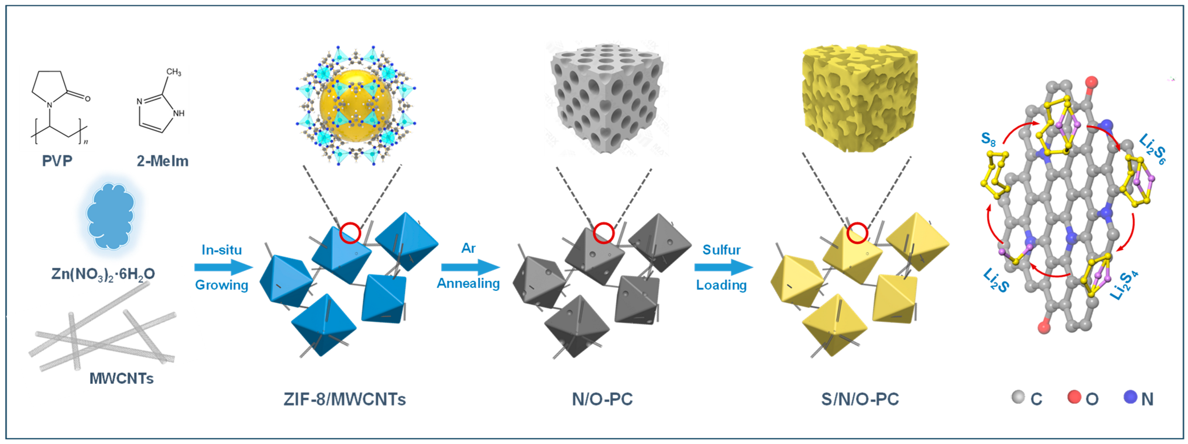
2.2. Synthesis of N/O-PC Composite

The N/O-PC composite was constructed by the MWCNTs interconnecting N/O-doped porous carbon (~100 nm) via annealing the precursor of large-size zeolitic imidazolate framework-8 (ZIF-8) grown in situ on MWCNTs. The MWCNTs need to undergo activation treatment before use to increase their surface active sites and promote ZIF-8 growth on their surface. In the typical activation process, the MWCNTs were pre-activated in concentrated HNO3 solution at 110 °C for 2 h to generate hydrophilic surface structures with oxygen-containing functional groups. Subsequently, the MWCNTs were washed three times with deionized water and then dried at 80 °C for 12 h to obtain the activated MWCNTs. After that, 300 mg activated MWCNTs and 6.0 mmol 2-MeIm were added into 400 mL methanol solution containing 200 mg 2-Melm under vigorous stirring for 2 h to form homogeneous ink. Next, 800 mL methanol containing 3.0 mmol Zn (NO3)2·6H2O was transferred into the above-mentioned MWCNTs solution and the resulting mixture was allowed to react for 24 h at room temperature to form the ZIF-8/MWCNTs precursors. The obtained ZIF-8/MWCNTs precursors were collected by centrifugation at 9000 rpm for 10 min, washed three times with methanol and deionized water and then dried in vacuum at 80 °C overnight. Finally, annealing the as-obtained ZIF-8/MWCNTs precursors under Ar atmosphere in a tube furnace at 950 °C for 3 h with a ramp rate of 2 °C min−1 yielded the N/O-PC composite.

2.3. Fabrication of S/N/O-PC Composite

The S/N/O-PC composite was prepared by a simple method of solution infiltration and heat treatment. First, the N/O-PC composite was activation treated at 100 °C maintained for 8 h. Then, 200 mg sulfur powder was dissolved in 10 mL CS2 solution. Subsequently, N/O-PC composite was immersed in sulfur/CS2 solution for 96 h, in which the mass ratio of N/O-PC composite and sulfur was 1 to 4. Then, the mixture was dried at 60 °C for 2 h at room temperature. The mixture was heated at 155 °C for 12 h in a sealed autoclave under Ar, generating the S/N/O-PC composite. The fabrication processes of S/N/O-PC are illustrated in Figure 1. Also, the S/carbon black (S/C) composite was prepared by using a method similar to that used for constructing the S/N/O-PC composite.

2.4. Materials Characterization

X-ray diffraction (XRD) patterns were collected using a SmartLab3KW X-ray diffractometer equipped with Cu-Kα radiation (λ = 0.1540 nm). The measurements were conducted at 40 kV and 40 mA, with a scanning rate of 10° min−1 in a 2θ range of 10–80°. Scanning electron microscopy (SEM) and transmission electron microscopy (TEM) experiments were performed using a Phenom ProX SEM and a JEM1200EX high-resolution TEM, respectively. Thermal gravimetric analysis (TGA) and differential scanning calorimetry (DSC) were carried out using a TGA2 thermogravimetric analyzer in an argon atmosphere. The scan rate was set at 10 °C min−1, covering a temperature range from room temperature to 800 °C. The Brunauer–Emmett–Teller (BET) surface area was determined by analyzing nitrogen adsorption isotherms using an Autosorb iQ3 automated gas sorption system.

2.5. Electrochemical Measurement

For the S/N/O-PC cathodes, S/N/O-PC composite, super P, and PVDF in a weight ratio of 8:1:1 were mixed in NMP to form a uniform slurry that was then coated onto Al foil. For comparison, the S/C cathodes were also prepared by using a process similar to fabricating the S/N/O-PC cathodes. Sulfur cathodes, Li foil anodes, commercial PP separators, and 40 μL electrolyte (0.5 M LiCF3SO3, 0.5 M LiNO3 in DME:DOL = 1:1 vol%) were used to assemble CR2025 coin-type cells for electrochemical measurements. Cyclic voltammetry (CV) measurements were performed using a CHI760e electrochemical workstation (Shanghai Chenhua Instrument, Shanghai, China) with a scan rate of 0.1 mV s−1 and a voltage range of 1.7–2.8 V. Electrochemical impedance spectroscopy (EIS) was conducted using a PARSTAT 2273 within a frequency range of 10−1–105 Hz. Galvanostatic charge/discharge tests were carried out using a battery test system (LAND CT2001A). The S/N/O-PC cathodes were cycled by using galvanostatic charge-discharge at a current density of 0.2 C with a voltage range of 1.7 V to 2.8 V. The cycling stability of the S/N/O-PC cathode is reflected by plotting the specific capacity versus the number of cycles. The rate performance of the S/N/O-PC cathode was investigated by using galvanostatic charge–discharge at gradual charge/discharge rates from 0.2, 0.5, 1, 2, 3 to 5 C with each current density cycled for 5 cycles. The rate performance of the S/N/O-PC cathode was demonstrated by the plotted curve of the specific capacity versus the current density.

3. Results and Discussion

MOFs possess a porous structure and high porosity, which make them ideal precursors for porous carbon materials [19]. In the process of pyrolysis of MOFs, MOF-derived porous carbon materials agglomerate. Multiwalled carbon nanotubes (MWCNTs) have a unique structure in which carbon atoms are bonded together in a hexagonal lattice, forming tubes with a diameter of nanometers. Thus, carbon nanotubes can effectively address the agglomeration issues of MOF-derived porous carbon. In this paper, we used MWCNTs to support ZIF-8 [29,30]. The morphologies of MWCNTs were characterized by SEM and TEM techniques. The MWCNTs feature an even surface (Figure 2a–c) and a diameter distribution from 10 to 30 nm with average diameter of 19.9 nm (Figure S1).
After in situ growth of ZIF-8 nanoparticles on MWCNTs and pyrolysis of the precursor, their morphologies have been changed significantly. Figure 2d,e shows the SEM images of N/O-PC. A large number of carbon nanoparticles (particle sizes ranging from 100 to 200 nm with an average particle size of 150.5 nm (Figure S2) are interconnected in series by the MWCNTs, resulting in the formation of necklace-like structures. TEM images (Figure 2f) clearly indicate that the MWCNTs penetrate through the carbon nanoparticle. The N/O-PC necklace-like structure not only provides three-dimensional interconnected electron transport paths, but also effectively alleviates the detachment of active materials caused by the volume change of sulfur during the charge–discharge process [31,32,33,34,35].
Figure 3a shows the XRD patterns of the ZIF-8, ZIF-8/MWCNT and N/O-PC composites. The ZIF-8 peaks are similar to that in previous work, indicating the successful synthesis of ZIF-8 crystals [36]. The peaks are sharp, indicating a high crystallinity degree of ZIF-8. For the XRD pattern of ZIF-8/MWCNTs, it is similar to that of the ZIF-8 crystal, which indicates the successful synthesis of ZIF-8 on MWCNTs. The XRD pattern of the N/O-PC composite shows a broad diffraction peak around 26°, which is characteristic of amorphous carbon. Additionally, a weak peak can be observed at around 44°, which belongs to graphite [37,38]. This weak peak suggests that the NCPs exhibit some level of graphitization. Figure 3b shows the N2 adsorption–desorption isotherm of the N/O-PC composite. It can be observed that the N/O-PC composite exhibits typical Type I isotherms. At a relative low pressure (P/P0 < 0.1), the adsorption shows a steep increase, indicating the presence of a large number of micropores. Between the relative pressures of 0.8 to 1.0, a hysteresis loop appears, which is characteristic of mesopores [39]. These results indicate the co-existence of micropores and mesopores in the N/O-PC composite. The pore size distribution is typically quantified using the Barrett–Joyner–Halenda (BJH) method, which is applied to the desorption branch of the nitrogen adsorption isotherm. Figure S3 illustrates the pore size distribution of the N/O-PC composite. The pore size of the N/O-PC composite is mainly at 1.2 nm, corresponding to micropores. Additionally, the specific surface area of the N/O-doped porous carbon (N/O-PC) can be measured using the Brunauer–Emmett–Teller (BET) method, which is applied to the isotherm data in the relative pressure range to calculate the surface area. The surface area and the pore volume of the N/O-PC composite were measured to be 504.7 m2 g−1 and 0.18 cm3 g−1, respectively [40]. As a sulfur host, the N/O-PC composite exhibits a high specific surface area and pore volume, which allows more sulfur accommodation and reduces the dissolution and diffusion of the polysulfides and provides pathways for electron and ion transport [41,42]. The XPS technique was applied in the identification of the chemical composition and electronic states of the N/O-PC composite. As shown in Figure S4, the full spectrum clearly reveals the presence of C, N, and O, and a small amount of un-gasified Zn on the surface of the derivatives. Based on the XPS data, the atomic ratio of the doped N to O was found to be 1.43. Figure 3c shows the electronic states of O in N/O-PC. Two deconvoluted peaks correspond to O-O (533.3 eV) and C-O (532.4 eV), respectively. Figure 3d shows the electronic states of N in N/O-PC. Four deconvoluted peaks correspond to pyridinic N (398.5 eV), Zn-N (399.4 eV), graphitic N (401.0 eV), and pyrrolic N (401.5 eV), respectively [43,44,45]. Lithium polysulfides can be adsorbed and catalyzed through nitrogen and oxygen heteroatoms of the carbon matrix.
To investigate the structure of S/N/O-PC, we performed XRD analysis. Figure 4a shows the XRD patterns of the pure S and S/N/O-PC composite. For the S/N/O-PC composite, no obvious crystalline S peaks are observed, indicating that sulfur is filled in the micropores of the N/O-PC composite. To determine the sulfur content in the S/N/O-PC composite, we conducted TGA [44,46]. As shown in Figure 4b, the sulfur content was 63.1 wt%. It is worth noting that there was no sulfur evaporation below 200 °C due to the sulfur nanoparticles filled in the micropores of the N/O-PC composite. We further performed nitrogen adsorption–desorption measurements for S/N/O-PC. As shown in Figure 4c, the surface area decreased from 504.70 m2 g−1 of the N/O-PC to 61.4 m2 g−1 of the S/N/O-PC. Additionally, the micropore volume also reduced dramatically from 0.18 cm3 g−1 of the N/O-PC to 0.01 cm3 g−1 of the S/N/O-PC, based on changes in the pore size distribution before and after sulfur loading (Figure 4d). These findings confirm that almost all sulfur is filled into the micropores of the N/O-PC. In addition, the EDS elemental mapping images (Figure S5) unambiguously illustrate that the S, C, N and O elements are evenly distributed over the entire architecture at the nano level.
To evaluate the electrochemical performance of S/N/O-PC, cyclic voltammetry (CV) was tested first. Figure 5a shows the CV curves of the S/N/O-PC and S/C cathodes at a scan rate of 0.1 mV s−1. It can be observed that the S/N/O-PC cathode exhibits two reduction peaks and one oxidation peak. The first reduction peak occurs around 2.3 V, corresponding to the reduction of S to soluble long-chain polysulfides (Li2S4-8). The second reduction peak is around 2.0 V, corresponding to the reduction from Li2S4-8 to insoluble product Li2S2/Li2S. The oxidation peak occurs around 2.41 V, which belongs to the conversion of Li2S2/Li2S into elemental sulfur and lithium. Although the CV curve of the S/C cathode also shows two reduction peaks and one oxidation peak, the current of the oxidation/reduction peaks are much smaller and the voltage polarization is much larger than those of the S/N/O-PC cathode, indicating the excellent electrocatalytic conversion of the polysulfides on S/N/O-PC. The galvanostatic charge/discharge profiles of the S/N/O-PC and S/C cathodes at 0.2 C (1 C = 1675 mA g−1) are presented in Figure 5b, in which a charge plateau and two discharge plateaus can be apparently observed, consistent with the CV result [47]. There are also noticeable differences in the voltage gap between the charge and discharge voltage plateaus, which are associated with the reaction kinetics and the reversibility of the polysulfide redox reactions. Rather than the S/C cathode, the S/N/O-PC cathode delivers a voltage gap, implying the kinetically efficient reaction process in the S/N/O-PC cathode. Figure 5c shows the cycling performance of the S/N/O-PC and S/C cathodes at 0.2 C. The initial discharge capacity of the S/N/O-PC cathode is 1032.8 mA h g−1, which is higher than that of the S/C cathode (862.4 mA h g−1). After 100 cycles, the discharge capacity of S/N/O-PC maintained 685.9 mA h g−1, corresponding to a 66.4% capacity retention rate. In contrast, the S/C cathode displayed a low capacity retention of 38.6%. Meanwhile, the S/N/O-PC kept a relatively high Coulombic efficiency of above 99% over the 100 cycles at 0.2 C, which is significantly superior to that of the S/C, implying efficient kinetics of the polysulfide redox reactions in the S/N/O-PC cathode. Figure 5d shows that the S/N/O-PC has small peak of negative potential at the beginning of the second discharge voltage plateau, suggesting a low overpotential for the reaction of Li2S4 to Li2S2. Also, Figure 5e shows that the S/N/O-PC has a small peak of positive potential at the start of the first charge voltage plateau, indicating a low overpotential for the reaction of Li2S to Li2S4-8. These show that S/N/O-PC displays a low overpotential during both the discharge and charge processes, which is in line with the enhanced kinetics of the polysulfide redox reactions in the S/N/O-PC cathode.
The improvement in the performance of our S/N/O-PC cathode can be attributed to the advantages of the N/O-PC host. First, the N/O-PC composite has a high specific surface area and porous structure, which provide more sites for the physical adsorption of polysulfides, preventing their diffusion and dissolution in the electrolyte. Secondly, doping high electronegativity N and O into the carbon lattice can effectively disrupt the electrical neutrality of the adjacent carbon atoms and form active sites for adsorbing lithium polysulfides by forming chemical bonds, immobilizing the lithium polysulfides in the cathode region and inhibiting the shuttle of lithium polysulfides. Additionally, oxygen-doped carbon has surface functional groups such as hydroxyl, carbonyl, and carboxyl groups. These groups can interact with polysulfides through hydrogen bonds or other chemical bonds, further enhancing the chemical adsorption of polysulfides. More importantly, a stronger interaction between doped N/O and carbon atoms can promote the charge redistribution to form catalytic active sites for redox reactions of adsorbing lithium polysulfides. Then, since MWCNTs are flexible and have a relatively low volume expansion, they can effectively accommodate the volume expansion of S during cycling and improve the cycling performance of the S/N/O-PC cathode. Moreover, NCPs and MWCNTs are chemically stable in the operating conditions of LSBs, which contributes to the overall stability of the battery. Finally, lithium polysulfides can be adsorbed and catalyzed through nitrogen and oxygen heteroatoms of the carbon matrix (Figure 5f).
The electrode kinetics were studied by using electrochemical impedance spectroscopy (EIS) technology. Figure S6 shows the Nyquist plots of the cells with the S/N/O-PC collected before cycling and after 100 cycles, which are composed of a depressed semicircle and a linear section in the high- and low-frequency regions, respectively. The depressed semicircle corresponds to charge-transfer resistance when the electrons transfer from confined sulfur to the NCPs hosts and then to the MWNTs network. The linear section is associated with the Warburg impedance (W) related to the ionic diffusion. The charge-transfer resistance of the S/N/O-PC decreases after 100 cycles, which further confirms that the sulfur-loaded N/O-PC with high conductivity can significantly accelerate the kinetics of polysulfide redox reactions by reducing the charge-transfer resistance of electrochemical reactions [48]. The rate performance of the S/N/O-PC cathode was evaluated by cycling at gradual rates from 0.2 C to 5 C. As shown in Figure 6a, discharge capacities of 1018.2, 890.2, 775.1, 722.7, 640.4, and 579.6 mAh g−1 were obtained for the S/N/O-PC at rates of 0.2, 0.5, 1.0, 2.0, 3.0 and 5.0 C, respectively, which were always higher than that of the S/C at the same rate. When the rate was set back to 0.2 C, the discharge capacity of the S/N/O-PC was still stable, about 1017.9 mAh g−1, which is significantly higher than that of the S/C cathode. More notably, when the rate exceeded 1 C, the second discharge voltage plateau corresponding to the reduction from Li2S4-8 to the insoluble product Li2S2/Li2S completely disappeared (Figure 6c), indicating poor conversion efficiency. In contrast, the S/N/O-PC cathode displayed an obvious second discharge voltage plateau even at a large rate of 5 C (Figure 6b), suggesting efficient catalytic performance toward conversion of Li2S4-8 to the insoluble product Li2S2/Li2S.
Additionally, compared with the S/C cathode, the S/N/O-PC cathode has a small voltage gap between the charge and discharge voltage plateaus as well as a low polarization. The N/O-PC composite has excellent electrical conductivity, which helps in efficient electron transport during the charge and discharge cycles, reducing the internal resistance of the battery and improving its rate capabilities. Thus, these LSBs can deliver and accept high currents, making them suitable for applications that require rapid energy release or recharge. Additionally, the performances of the S/N/O-PC cathodes can also compete with various reported sulfur composite cathodes in the literature (Table S1). Especially for high current discharge, the S/N/O-PC cathode still delivers high discharge capacity. This is due to the high catalytic activity of N/O-PC, which can accelerate the redox reaction kinetics of lithium polysulfides.

4. Conclusions

In summary, we successfully designed a novel structure that embeds O/N-doped porous carbon into a multiwalled carbon nanotubes network (N/O-PC). The structure possesses a three-dimensional conductive network, a high specific surface area, and abundant active sites. These characteristics enable effective adsorption of lithium polysulfides, thereby efficiently suppressing the “shuttle effect” of lithium polysulfides and improving the redox kinetics of the sulfur cathode. As a result, the S/N/O-PC showed a high discharge capacity of 685.9 mA h g−1 at 0.2 C after 100 cycles. Moreover, the S/N/O-PC showed excellent rate performance (discharge capacities of 1018.2, 890.2, 775.1, 722.7, 640.4, and 579.6 mAh g−1 at gradual increasing rates of 0.2, 0.5, 1.0, 2.0, 3.0, and 5.0 C). This unique structural design provides an effective approach for constructing high-performance lithium–sulfur batteries with high energy density.

Supplementary Materials

The following supporting information can be downloaded at: https://www.mdpi.com/article/10.3390/c10030067/s1.

Author Contributions

Conceptualization, X.S. and N.Y.; Methodology, X.S., H.W. and N.Y.; Software, X.S.; Validation, Y.Y. and Z.Y.; Formal analysis, X.S., H.W. and N.Y.; Investigation, X.S., Y.Y., Z.Y., H.W. and N.Y.; Resources, X.S., H.W. and N.Y.; Writing—original draft preparation, X.S., H.W. and N.Y.; Writing—review and editing, N.Y.; Visualization, X.S. and N.Y.; Project administration, X.S.; Funding acquisition, H.W. and N.Y. All authors have read and agreed to the published version of the manuscript.

Funding

This work was financially supported by the Natural Science Foundation of Xiamen City (grant number 3502Z20227321).

Data Availability Statement

The data supporting the findings of this study are available within the article.

Acknowledgments

The author acknowledges fruitful discussion with Z.Y. and H.Q. from Nanjing Tech University.

Conflicts of Interest

The authors declare no conflict of interest.

References

  1. Zhang, Z.; Zhao, D.; Xu, Y.; Liu, S.; Xu, X.; Zhou, J.; Gao, F.; Tang, H.; Wang, Z.; Wu, Y.; et al. A review on electrode materials of fast-charging lithium-ion batteries. Chem. Rec. 2022, 22, e202200127. [Google Scholar] [CrossRef] [PubMed]
  2. Ao, S.; Gouda, S.P.; Selvaraj, M.; Boddula, R.; Al-Qahtani, N.; Mohan, S.; Rokhum, S.L. Active sites engineered biomass-carbon as a catalyst for biodiesel production: Process optimization using RSM and life cycle assessment. Energy Convers. Manag. 2024, 300, 117956. [Google Scholar] [CrossRef]
  3. Ren, J.; Wang, Z.; Xu, P.; Wang, C.; Gao, F.; Zhao, D.; Liu, S.; Yang, H.; Di, W.; Niu, C.; et al. Porous Co2VO4 nanodisk as a high-energy and fast-charging anode for lithium-ion batteries. Nano Micro Lett. 2021, 14, 5. [Google Scholar] [CrossRef] [PubMed]
  4. Zhang, F.; Zhou, Y.; Zhang, Y.; Li, D.; Huang, Z. Facile synthesis of sulfur@titanium carbide Mxene as high performance cathode for lithium-sulfur batteries. Nanophotonics 2020, 9, 2025–2032. [Google Scholar] [CrossRef]
  5. Baumann, A.E.; Han, X.; Butala, M.M.; Thoi, V.S. Lithium thiophosphate functionalized zirconium MOFs for Li-S batteries with enhanced rate capabilities. J. Am. Chem. Soc. 2019, 141, 17891–17899. [Google Scholar] [CrossRef] [PubMed]
  6. Yin, C.; Li, Z.; Zhao, D.; Yang, J.; Zhang, Y.; Du, Y.; Wang, Y. Azo–branched covalent organic framework thin films as active separators for superior sodium–sulfur batteries. ACS Nano 2022, 16, 14178–14187. [Google Scholar] [CrossRef] [PubMed]
  7. Zhao, D.; Ge-Zhang, S.; Zhang, Z.; Tang, H.; Xu, Y.; Gao, F.; Xu, X.; Liu, S.; Zhou, J.; Wang, Z.; et al. Three–dimensional honeycomb–like carbon as sulfur host for sodium–sulfur batteries without the shuttle effect. ACS Appl. Mater. Interfaces 2022, 14, 54662–54669. [Google Scholar] [CrossRef]
  8. Zhao, Q.; Wang, R.; Wen, J.; Hu, X.; Li, Z.; Li, M.; Pan, F.; Xu, C. Separator engineering toward practical Li-S batteries: Targeted electrocatalytic sulfur conversion, lithium plating regulation, and thermal tolerance. Nano Energy 2022, 95, 106982. [Google Scholar] [CrossRef]
  9. Zhou, C.; Li, Z.; Xu, X.; Mai, L. Metal-organic frameworks enable broad strategies for lithium-sulfur batteries. Natl. Sci. Rev. 2021, 8, nwab055. [Google Scholar] [CrossRef]
  10. Cao, G.; Bi, D.; Zhao, J.; Zheng, J.; Wang, Z.; Lai, Q.; Liang, Y. Transformation of ZIF-8 nanoparticles into 3D nitrogen-doped hierarchically porous carbon for Li–S batteries. RSC Adv. 2020, 10, 17345–17352. [Google Scholar] [CrossRef]
  11. Du, X.-L.; You, Y.; Yan, Y.; Zhang, D.; Cong, H.-P.; Qin, H.; Zhang, C.; Cao, F.-F.; Jiang, K.-C.; Wang, Y.; et al. Conductive carbon network inside a sulfur-impregnated carbon sponge: A bioinspired high-performance cathode for li–s battery. ACS Appl. Mater. Interfaces 2016, 8, 22261–22269. [Google Scholar] [CrossRef] [PubMed]
  12. Yoshie, Y.; Hori, K.; Mae, T.; Noda, S. High-energy-density Li-S battery with positive electrode of lithium polysulfides held by carbon nanotube sponge. Carbon 2021, 182, 32–41. [Google Scholar] [CrossRef]
  13. Gueon, D.; Yoon, J.; Hwang, J.T.; Moon, J.H. Microdomain sulfur-impregnated CeO2-coated CNT particles for high-performance Li-S batteries. Chem. Eng. J. 2020, 390, 124548. [Google Scholar] [CrossRef]
  14. Li, H.; Shao, F.; Wen, X.; Ding, Y.; Zhou, C.; Zhang, Y.; Wei, H.; Hu, N. Graphene/Mxene fibers-enveloped sulfur cathodes for high-performance Li-S batteries. Electrochim. Acta 2021, 371, 137838. [Google Scholar] [CrossRef]
  15. Hong, X.; Liang, J.; Tang, X.; Yang, H.; Li, F. Hybrid graphene album with polysulfides adsorption layer for Li-S batteries. Chem. Eng. Sci. 2019, 194, 148–155. [Google Scholar] [CrossRef]
  16. Qiu, S.; Zhang, J.; Liang, X.; Li, Y.; Cui, J.; Chen, M. Tunable MOFs derivatives for stable and fast sulfur electrodes in Li-S batteries. Chem. Eng. J. 2022, 450, 138287. [Google Scholar] [CrossRef]
  17. Chen, Y.; Zhang, L.; Pan, H.; Zhang, J.; Xiang, S.; Cheng, Z.; Zhang, Z. Pore-space-partitioned MOF separator promotes high-sulfur-loading Li-S batteries with intensified rate capability and cycling life. J. Mater. Chem. A 2021, 47, 26929–26938. [Google Scholar] [CrossRef]
  18. Chenxi, Y.; Liping, T.; Bo, W.; Hulin, T.; Xinyue, L.; Jian, C.; Mengyao, G.; Naiqiang, L. NiCoSe4@CNFs derived from MOF compounds enabling robust polysulfide adsorption and catalysis in Li-S batteries. J. Alloys Compd. 2023, 957, 170449. [Google Scholar]
  19. Xiaohua, C.; Mi, Z.; Jin, Z.; Juan, W.; Zengbao, J.; Yong, L. Boosting electrochemical performance of Li-S batteries by cerium-based MOFs coated with polypyrrole. J. Alloys Compd. 2022, 901, 163649. [Google Scholar]
  20. Zhang, H.; Zhao, W.; Zou, M.; Wang, Y.; Chen, Y.; Xu, L.; Wu, H.; Cao, A. 3D, mutually embedded MOF@Carbon nanotube hybrid networks for high—performance lithium—sulfur batteries. Adv. Energy Mater. 2018, 819, 1614–6832. [Google Scholar] [CrossRef]
  21. Bi, T.; Zheng, W.; Zhou, Y.; Lin, Q.; Zhang, X. Three-dimensional N, S co-doped ultra-thin-walled hierarchical porous carbon as sulfur-loading host for high-performance lithiumsulfur battery. J. Energy Storage 2024, 93, 112428. [Google Scholar] [CrossRef]
  22. Haina, C.; Jingyu, S.; Menglei, W.; Yan, H.; Zixiong, S. A review in rational design of graphene toward advanced Li-S batteries. Nano Res. Energy 2023, 2, E9120054. [Google Scholar]
  23. Ye, H.; Li, Y. Towards practical lean-electrolyte Li-S batteries: Highly solvating electrolytes or sparingly solvating electrolytes? Nano Res. Energy 2022, 1, e9120012. [Google Scholar] [CrossRef]
  24. Liu, H.; Liu, F.; Qu, Z.; Chen, J.; Liu, H.; Tan, Y.; Guo, J.; Yan, Y.; Zhao, S.; Zhao, X.; et al. High sulfur loading and shuttle inhibition of advanced sulfur cathode enabled by graphene network skin and N, P, F-doped mesoporous carbon interfaces for ultra-stable lithium sulfur battery. Nano Res. Energy 2023, 2, E912049. [Google Scholar] [CrossRef]
  25. Xue, H.; Gong, H.; Yamauchi, Y.; Sasaki, T.; Ma, R. Photo-enhanced rechargeable high-energy-density metal batteries for solar energy conversion and storage. Nano Res. Energy 2022, 1, E9120007. [Google Scholar] [CrossRef]
  26. Wu, Z.; Wang, L.; Chen, S.; Zhu, X.; Deng, Q.; Wang, J.; Zeng, Z.; Deng, S. Facile and low-temperature strategy to prepare hollow ZIF-8/CNT polyhedrons as high-performance lithium-sulfur cathodes. Chem. Eng. J. 2020, 404, 126579. [Google Scholar] [CrossRef]
  27. Jeon, Y.; Lee, J.; Jo, H.; Hong, H.; Lee, L.Y.S.; Piao, Y. Co/Co3O4-embedded n-doped hollow carbon composite derived from a bimetallic MOF/ZnO core-shell template as a sulfur host for li-s batteries. Chem. Eng. J. 2020, 407, 126967. [Google Scholar] [CrossRef]
  28. Fan, B.; Zhao, D.; Zhou, W.; Xu, W.; Liang, X.; He, G.; Wu, Z.; Li, L. Nitrogen—doped hollow carbon polyhedrons with carbon nanotubes surface layers as effective sulfur hosts for high—rate, long—lifespan lithium–sulfur batteries. ChemElectroChem 2020, 724, 4990–4998. [Google Scholar] [CrossRef]
  29. Chen, P.; Wang, T.; Tang, F.; Chen, G.; Wang, C. Elaborate interface design of CoS2/Fe7S8/NG heterojunctions modified on a polypropylene separator for efficient lithium-sulfur batteries. Chem. Eng. J. 2022, 446, 136990. [Google Scholar] [CrossRef]
  30. Liu, G.; Zeng, Q.; Fan, Z.; Tian, S.; Li, X.; Lv, X.; Zhang, W.; Tao, K.; Xie, E.; Zhang, Z. Boosting sulfur catalytic kinetics by defect engineering of vanadium disulfide for high-performance lithium-sulfur batteries. Chem. Eng. J. 2022, 448, 137683. [Google Scholar] [CrossRef]
  31. Feng, H.; Zhang, M.; Kang, J.; Su, Q.; Du, G.; Xu, B. Nitrogen and oxygen dual-doped porous carbon derived from natural ficus microcarpas as host for high performance lithium-sulfur batteries. Mater. Res. Bull. 2019, 113, 70–76. [Google Scholar] [CrossRef]
  32. Yang, D.; Li, M.; Zheng, X.; Han, X.; Zhang, C.; Biendicho, J.J.; Llorca, J.; Wang, J.; Hao, H.; Li, J.; et al. Phase engineering of defective copper selenide toward robust lithium-sulfur batteries. ACS Nano 2022, 16, 11102–11114. [Google Scholar] [CrossRef] [PubMed]
  33. Yu, H.; Zhang, B.; Sun, F.; Jiang, G.; Zheng, N.; Xu, C.; Li, Y. Core-shell polyhedrons of carbon nanotubes-grafted graphitic carbon@nitrogen doped carbon as efficient sulfur immobilizers for lithium-sulfur batteries. Appl. Surf. Sci. 2018, 450, 364–371. [Google Scholar] [CrossRef]
  34. Geng, M.; Yang, H.; Shang, C. The multi-functional effects of CuS as modifier to fabricate efficient interlayer for Li-S batteries. Adv. Sci. 2022, 9, 202204561. [Google Scholar] [CrossRef] [PubMed]
  35. Yang, X.-X.; Li, X.-T.; Zhao, C.-F.; Fu, Z.-H.; Zhang, Q.-S.; Hu, C. Promoted deposition of three-dimensional Li2S on catalytic Co phthalocyanine nanorods for stable high-loading lithium-sulfur batteries. ACS Appl. Mater. Interfaces 2020, 1229, 32752–32763. [Google Scholar] [CrossRef] [PubMed]
  36. Yin, Y.; Xin, S.; Guo, Y.; Wan, L. Lithium-sulfur batteries: Electrochemistry, materials, and prospects. Angew. Chem. Int. Ed. 2013, 52, 13186–13200. [Google Scholar] [CrossRef] [PubMed]
  37. Uppugalla, S.; Pothu, R.; Boddula, R.; Desai, M.A.; Al-Qahtani, N. Nitrogen and sulfur co-doped activated carbon nanosheets for high-performance coin cell supercapacitor device with outstanding cycle stability. Emergent Mater. 2023, 6, 1167–1176. [Google Scholar] [CrossRef]
  38. Li, H.; Sun, L.; Zhao, Y.; Tan, T.; Zhang, Y. A novel CuS/graphene-coated separator for suppressing the shuttle effect of lithium/sulfur batteries. Appl. Surf. Sci. 2019, 466, 309–319. [Google Scholar] [CrossRef]
  39. Ma, F.; Srinivas, K.; Zhang, X.J.; Zhang, Z.H.; Wu, Y.; Liu, D.W.; Zhang, W.L.; Wu, Q.; Chen, Y.F. Mo2N quantum dots decorated n-doped graphene nanosheets as dual-functional interlayer for dendrite-free and shuttle-free lithium-sulfur batteries. Adv. Funct. Mater. 2022, 32, 2206113. [Google Scholar] [CrossRef]
  40. Chen, X.; Huang, Y.; Li, J.; Wang, X.; Zhang, Y.; Guo, Y.; Ding, J.; Wang, L. Bifunctional separator with sandwich structure for high-performance lithium-sulfur batteries. J. Colloid Interface Sci. 2020, 559, 13–20. [Google Scholar] [CrossRef]
  41. Fang, R.; Zhao, S.; Sun, Z.; Wang, D.; Cheng, H.; Li, F. More reliable lithium-sulfur batteries: Status, solutions and prospects. Adv. Mater. 2017, 29, 1606823. [Google Scholar] [CrossRef]
  42. Zou, K.; Zhou, T.; Chen, Y.; Xiong, X.; Jing, W.; Dai, X.; Shi, M.; Li, N.; Sun, J.; Zhang, S.; et al. Defect engineering in a multiple confined geometry for robust lithium-sulfur batteries. Adv. Energy Mater. 2022, 12, 2103981. [Google Scholar] [CrossRef]
  43. Wang, W.; Xi, K.; Li, B.; Li, H.; Liu, S.; Wang, J.; Zhao, H.; Li, H.; Abdelkader, A.M.; Gao, X.; et al. A Sustainable Multipurpose Separator Directed Against the Shuttle Effect of Polysulfides for High-Performance Lithium-Sulfur Batteries. Adv. Energy Mater. 2022, 12, 2200160. [Google Scholar] [CrossRef]
  44. Wang, M.; Bai, Z.; Yang, T.; Nie, C.; Xu, X.; Wang, Y.; Yang, J.; Dou, S.; Wang, N. Advances in high sulfur loading cathodes for practical lithium-sulfur batteries. Adv. Energy Mater. 2022, 12, 2201585. [Google Scholar] [CrossRef]
  45. Yang, M.; Liu, P.; Qu, Z.; Sun, F.; Tian, Y.; Ye, X.; Wang, X.; Liu, X.; Li, H. Nitrogen-vacancy-regulated Mo2N quantum dots electrocatalyst enables fast polysulfides redox for high-energy-density lithium-sulfur batteries. Nano Energy 2022, 104, 107922. [Google Scholar] [CrossRef]
  46. Chen, S.; Li, D.; Liu, Y.; Huang, W. Morphology-dependent defect structures and photocatalytic performance of hydrogenated anatase TiO2 nanocrystals. J. Catal. 2016, 341, 126–135. [Google Scholar] [CrossRef]
  47. Fan, F.Y.; Chiang, Y.-M. Electrodeposition kinetics in Li-S batteries: Effects of low electrolyte/sulfur ratios and deposition surface composition. J. Electrochem. Soc. 2017, 164, A917–A922. [Google Scholar] [CrossRef]
  48. Yang, M.; Wang, X.; Wu, J.; Tian, Y.; Huang, X.; Liu, P.; Li, X.; Li, X.; Liu, X.; Li, H. Dual electrocatalytic heterostructures for efficient immobilization and conversion of polysulfides in li-s batteries. J. Mater. Chem. A 2021, 9, 18477–18487. [Google Scholar] [CrossRef]
Figure 1. Schematic illustration of fabrication processes of S/N/O–PC.
Carbon 10 00067 g001
Figure 2. (a) SEM image, (b,c) TEM images of MWCNTs. (d) Low magnification, and (e) high magnification SEM image of N/O–PC, and (f) TEM image of S/N/O–PC.
Carbon 10 00067 g002
Figure 3. (a) XRD patterns of ZIF-8, ZIF-8/MWCNTs and N/O–PC. (b) Nitrogen adsorption–desorption isotherms for N/O–PC. (c) XPS high resolution of O 1s. (d) XPS high resolution of N 1s.
Carbon 10 00067 g003
Figure 4. (a) XRD patterns of crystalline S, S/N/O–PC. (b) TGA curves of crystalline S, S/N/O–PC. (c) Nitrogen adsorption–desorption isotherms for the S/N/O–PC. (d) The pore size distribution for S/N/O-PC.
Carbon 10 00067 g004
Figure 5. (a) CV curve of S/N/O-PC and S/C cathodes at a scan rate of 0.1 mV s−1. (b) Galvanostatic charge/discharge profiles of S/N/O−PC and S/C cathodes at 0.2 C. (c) Cycle performances of S/N/O−PC and S/C cathodes at 0.2 C. (d) Discharge and (e) charge profiles of S/N/O–PC and S/C cathodes at a scan rate of 0.1 mV s−1, indicating the overpotentials of solid–liquid phase conversion between soluble LiPSs and insoluble Li2S2/Li2S. (f) Schematic illustration of nitrogen and oxygen heteroatoms on N/O−PC catalyzed lithium polysulfides.
Carbon 10 00067 g005
Figure 6. (a) The rate performance of S/N/O−PC. (b,c) Charge/discharge curves of the S/N/O−PC and S/C cathodes at various rates, respectively.
Carbon 10 00067 g006
Disclaimer/Publisher’s Note: The statements, opinions and data contained in all publications are solely those of the individual author(s) and contributor(s) and not of MDPI and/or the editor(s). MDPI and/or the editor(s) disclaim responsibility for any injury to people or property resulting from any ideas, methods, instructions or products referred to in the content.

