1. Introduction
The field of electrochemical capacitors, with a focus on electrical double layer capacitors (EDLCs), is becoming increasingly popular in our day. Capacitors are energy storage devices that have a fast charging and discharging rate, a high energy density, and a long cycle lifetime [
1]. The ion storage mechanism of a supercapacitor/pseudo-capacitor is based on the Faradaic redox process [
2], whereas the ion storage mechanism of an EDLC is based on a non-redox process (adsorption process) [
3]. Both types of capacitors work on the same principle: two sandwiched electrodes are sandwiched in an electrolyte and set parallel to each other. The electrodes may or may not be separated by membranes, depending on the cell’s architecture.
Supercapacitors have been used in the fields of batteries, catalysis, and sensors, among other things [
4,
5], while EDLCs have been used in the field of desalination, energy storage, etc. [
6]. Because of their porosity, high surface area, and adsorption capabilities, carbon-based materials have been widely explored as capacitor sources [
7,
8]. Carbon, on the other hand, has some downsides—such as low hydrophilicity, low capacitance, and low conductivity, to name a few [
9]—and as a result, techniques to overcome these shortcomings have been the focus of recent research.
The use of chemical or physical methods to improve the physico-chemical properties of carbon via doping, additives, thermal annealing [
10], freeze drying technique [
11], and beam irradiation [
12], has been reported in literature. Due to their high porosity, large surface area, and regulated pores arrangement, carbon-based biopolymers such as cellulose and sucrose have recently gained attention as an alternative carbon source to commercial carbon (petrochemical product) [
13]. Mao et al. [
14] reported sucrose-based carbon with a specific capacitance of 316 F g
−1, while Yan et al. [
15] published N/S coal-based carbon with a specific capacitance of 301 F g
−1 in the literature. However, most of these precursors are expensive and hard to come by, necessitating the search for a low-cost alternative.
Carbons, because of their unique features—such as a large specific surface area, varied pore structure, and availability—have a lot of potential for long-term industrial use. Carbon materials with regulated macroscopic forms, such as beads, are, on the other hand, in high demand because they can suit the needs of most industrial applications.
In the literature, various types of functionalized activated carbon beads have been recorded with the goal of addressing specific applications. Steam, CO
2, ZnCl
2, and KOH activations [
16,
17,
18,
19], have all been studied and optimized for the manufacture of carbon materials with high surface areas and appropriate pore topologies for a variety of applications. However, the time and cost of the extensive post-synthesis modification methods prevent practical manufacture of carbon spheres on a wide scale. As a result, great emphasis was placed on making the preparation of activated carbon as simple as possible. By mixing an activating chemical (solid KOH and ZnCl
2) with biomass, Singh et al. observed a single-step activation. The synthesized activated biocarbon had a high BET surface area and good porosity, but its shape and particle size were not well characterized [
20,
21].
There is little or no well-established synthetic approach for producing carbon beads with the appropriate particle size and homogeneous pore size distribution at the moment to the best of our knowledge. As a result, a unique and efficient method of producing porous carbon spheres is very desirable. The usage of shaped polymer beads as a precursor to activated carbon beads is one option that could be pursued. Cation exchange resin beads are the most likely candidate among the industrially available shaped polymer beads to meet these requirements. They can be made in a variety of sizes and pore configurations. Furthermore, they provide evenly distributed ion exchange sites, allowing for the insertion of an activator that promotes the carbonization reaction and, as a result, the pore structure of the carbon beads. Therefore, the goal of this research is to make carbon beads with a well-defined spherical form and a mesoporous structure that could be employed as an EDLC while using resin beads as the starting material because of their acceptable particle size and morphology.
Because of the pore structure of cation exchange resin beads, the activator—in this case iron—is distributed uniformly, resulting in a very uniform carbonization reaction and in order to optimize the pore structure of the resultant carbon beads for surface charge improvement to promote better electron transport within the carbon structure, the resin beads were ion exchanged with FeCl3 solutions of various concentrations and carbonized at 700–900 °C (optimized temperature range for effective carbonization). Carbon spheres with a predetermined shape and size were created, as well as a mesopore network.
Aside from research on naturally occurring polymers—such as sucrose, glucose, and cellulose—synthetic polymers as carbon sources have recently been a subject of recent research in the EDLCs community, and there has been a report on the electrochemical behavior of carbon-based synthetic polymer sources in the literature [
22,
23]. Intense treatment conditions, such as thermal or hydrothermal breakdown, are required for the synthesis of graphitic carbon from precursory polymers. Due to the significant instability of the polymer backbone, oxygen-rich polymers—particularly those with unsaturated bonds and heteroatoms—have a strong tendency to decompose into carbon when heated. Prior to pyrolysis, the polymer undergoes a crosslinking phase (stabilization), which results in the transformation of the polymer into carbon. Under specific conditions, polymers such as polyacrylonitrile (PAN), polyethylene glycol (PEG), and polyethylene (PE) have been reported as carbon sources in the literature [
24,
25,
26,
27]. However, there are few reports in the literature about carbon-derived polystyrene sulphonate beads.
As a result of this, we studied the pyrolytic conditions and electrochemical behavior of carbon generated from this commercial polymeric-based precursor (polystyrene sulphonate beads) through chemical modification of the polymer followed by pyrolysis at various temperatures.
2. Materials and Methods
2.1. Materials
Polymer resin polystyrene sulphonate beads (DOWEX 50WX8-Hydrogen form CAS no: 217492-100G), polyvinylidenefluoride (PVDF) (CAS no. 24937-79-9), N-methyl-2-pyrrolidone (NMP) (CAS no. 872-50-4, 99.7%, M.W 99.13 g/mol), and sodium chloride (NaCl) were all purchased from Sigma Aldrich, Steinheim, Germany. Iron chloride hexahydrate (FeCl3·6H2O) (CAS no. 10625-77-1 99%, M.W 270.30 g/mol) was purchased from Merck, Sigma Aldrich, Germany.
Resin Pyrolysis and Activation
Briefly, 4.5 g of the polymer resin was put in a crucible boat and placed in a hollow tube furnace under pure nitrogen for 2 h at a ramp rate of 3°/min at different temperatures (700, 800, and 900 °C). After pyrolysis, the samples were named after their corresponding temperature—i.e., CS 700, CS 800, and CS 900.
For chemical activation, different molarities of FeCl3 (0.1, 0.3, and 0.5 M) were prepared and impregnated with 4.5 g of the polymer resin. The solution was stirred for 20 h. After, it was filtered, washed with distilled water, and dried overnight at 80 °C. The modified polymer resin was then pyrolyzed at a particular temperature under the same condition as mentioned above.
2.2. Experimental Procedure
Solid Electrode Preparation for CV and EIS Studies
Solid carbon electrode was prepared as a suspension of carbon sphere powder (0.3 g), and poly (vinylidene fluoride PVDF, 0.03 g) in 2 mL N-Methyl-2-pyrrolidone (NMP). The mixture was stirred for 3 h to ensure homogeneity and PVDF dissolution. Few drops of the slurry were then slowly deposited on a graphite sheet area of 1 cm2. The deposited electrode was dried at 80 °C in an oven for 2 h.
2.3. Physical Characterization
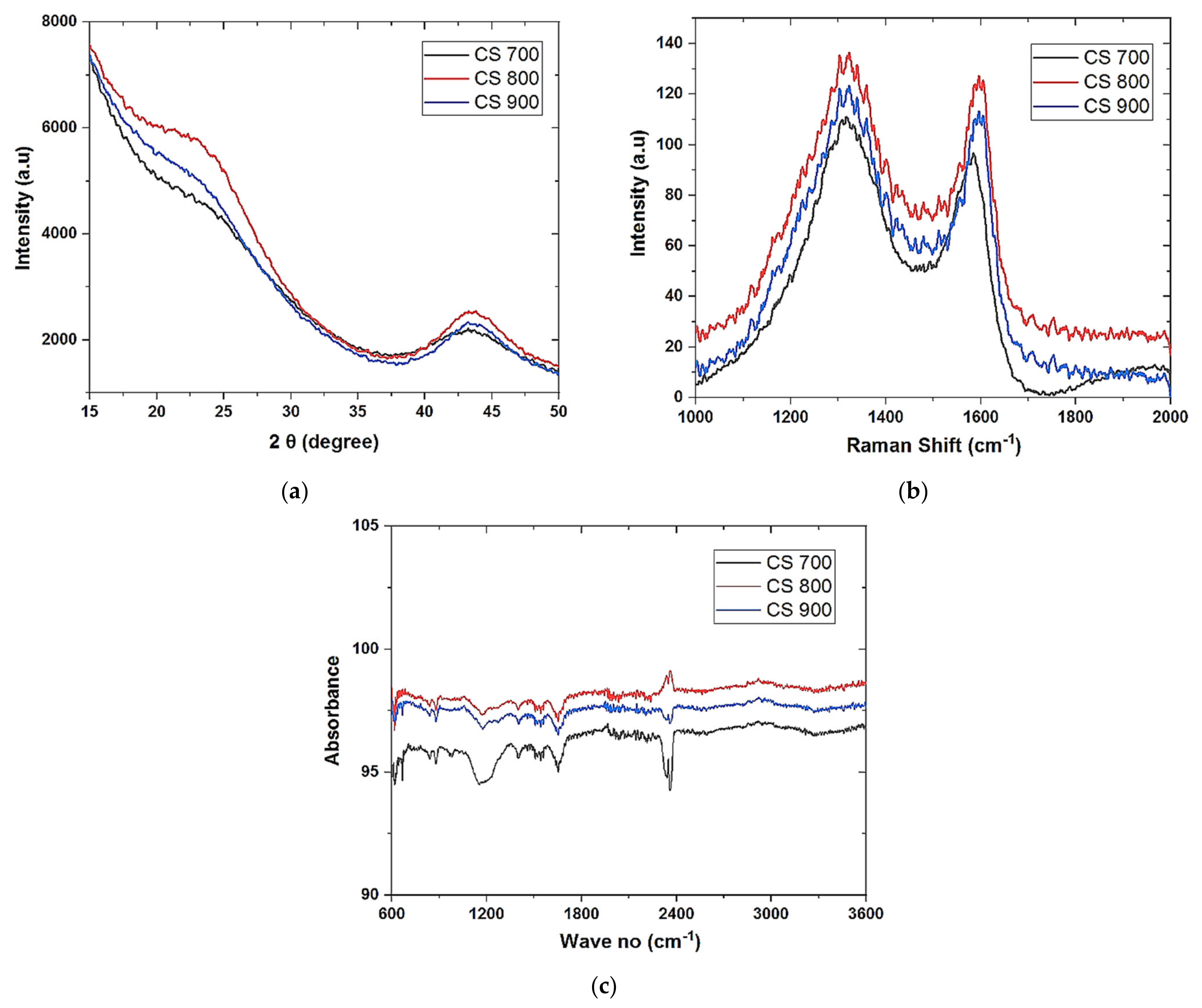
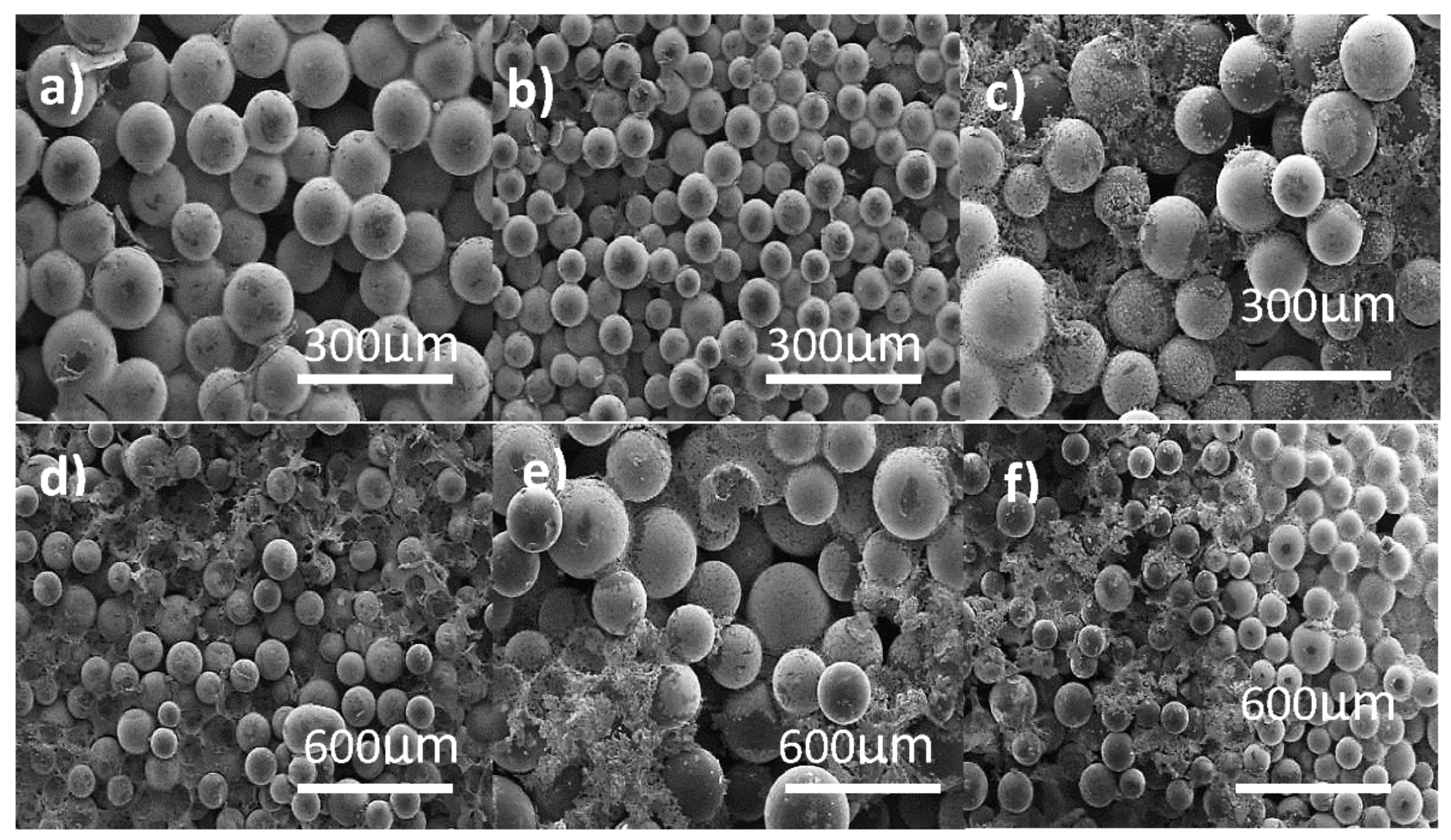
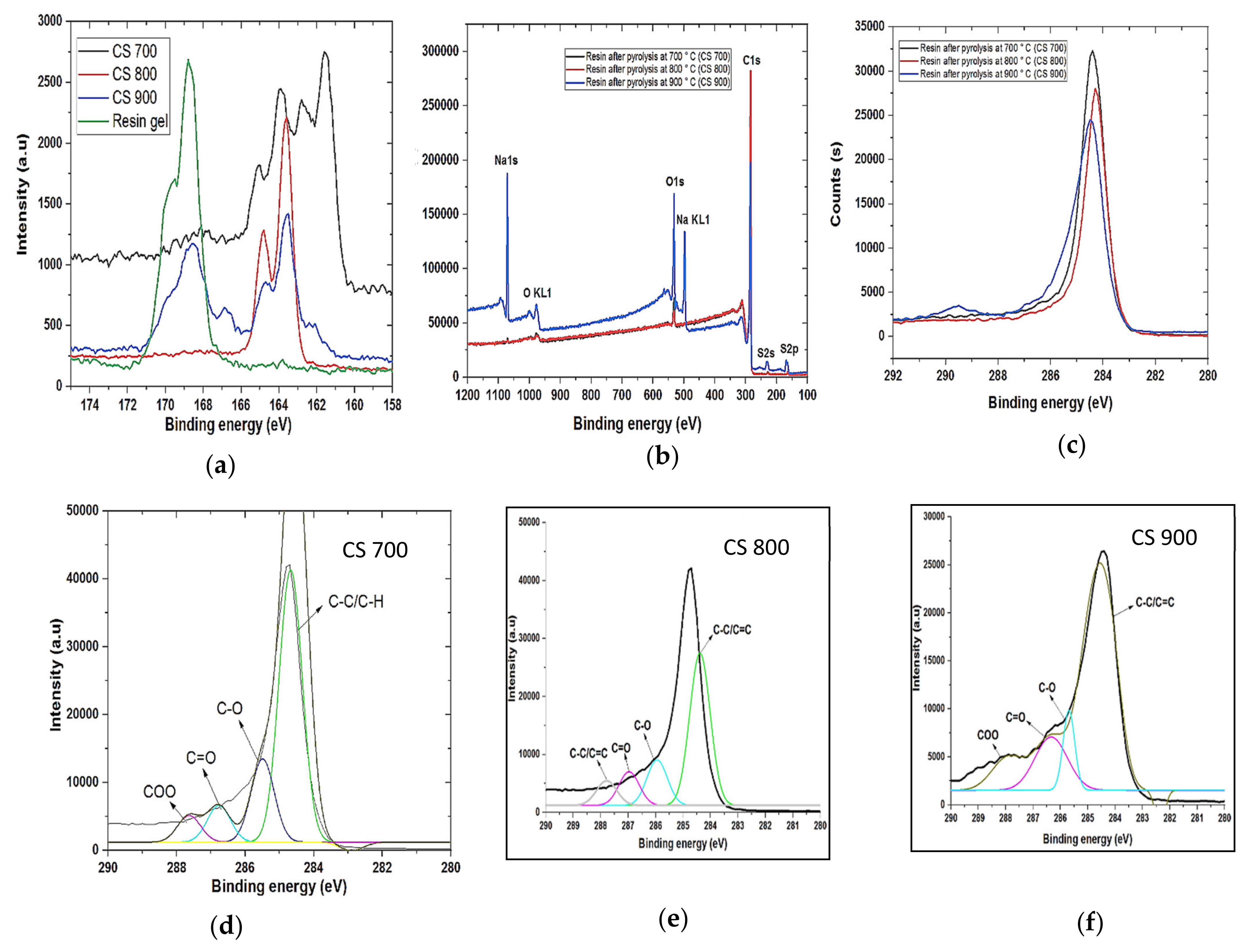
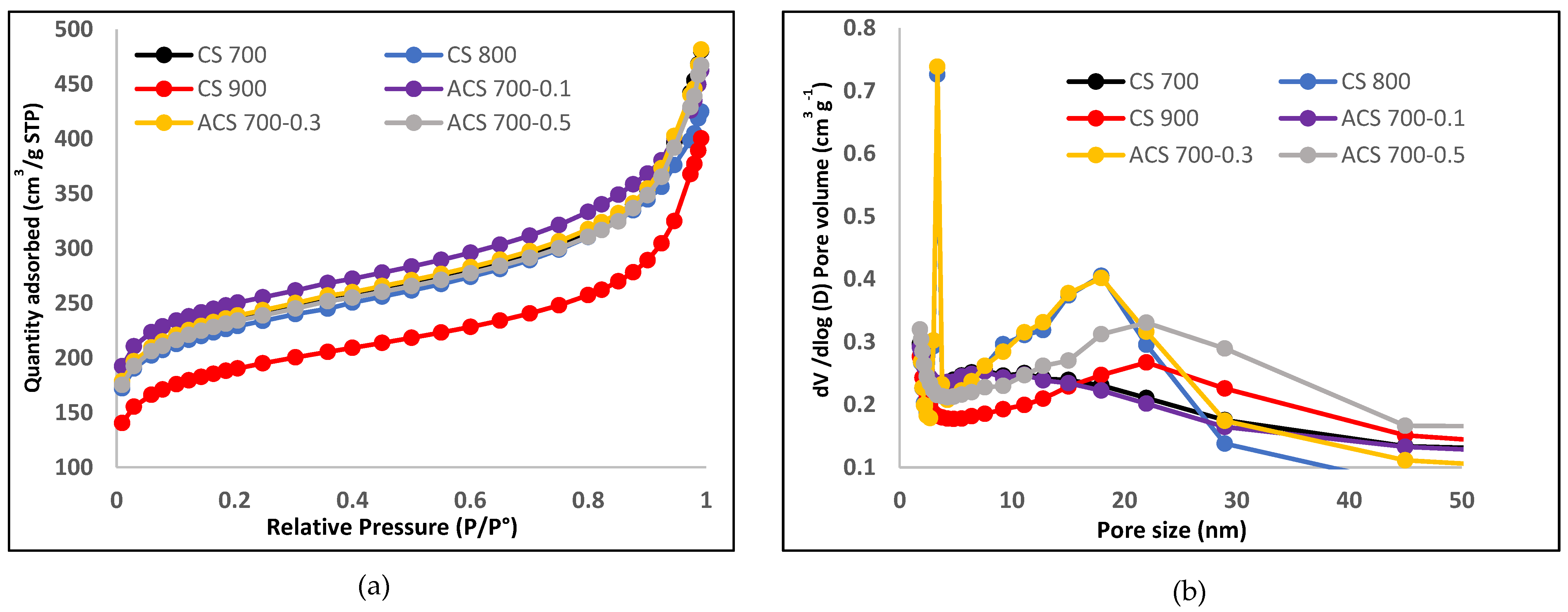
Field emission scanning electron microscopy (FESEM) was used to analyze the morphology of the samples (FESEM, Hitachi S4800, Tokyo, Japan). The structural properties were studied by using Raman spectroscopy (HORIBA Xplora, Minami-ku, Kyoto, Japan). X-ray diffractometer (XRD Pan Analytical X’pert Phillips, Lelyweg, EA, Almelo, The Netherlands) was used to reveal the crystallinity of the materials. Energy dispersive X-ray (EDX Oxford X-Max, Oxford, UK) and X-ray photon electron spectroscopy (XPS) (ESCALAB 250 Thermo Electron, Strasbourg, France) analyses were done to investigate the atomic composition and chemical functional groups (moities) of the materials. For the XPS analysis, the excitation source was a monochromatic source Al Kα anode with photo energy that was observed at 1486.6 eV. The analyzed surface has a diameter of 500 µm. The photoelectron spectra were calibrated in terms of bond energy with respect to the energy of the C=C component of carbon C1s at 284.4 eV and Fourier transmission infer-red (410 ATR FTIR spectrometer) was done to also verify the functional groups present in the materials. Specific surface area was obtained by using N2 adsorption/desorption at 77 K. SBET was the specific surface area calculated by the Brunauer–Emmett–Teller (BET) method (Micromeritics 2020 ASAP, Merignac, France). Vt was the total pore volume calculated from the amount adsorbed at a relative pressure (P/P°) of 0.99, Vmeso was the mesopore volume calculated by the Barrett–Joyner–Halenda (BJH) model.
2.4. Electrochemical Characterizations
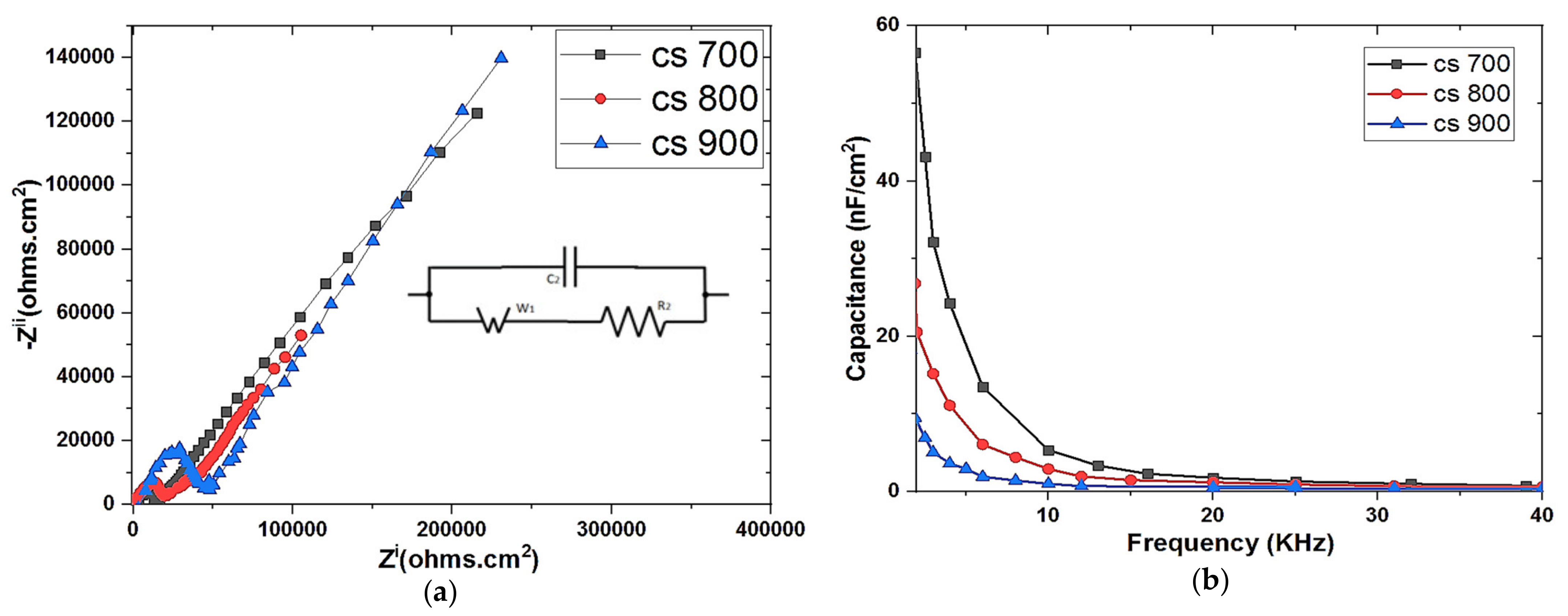
The electrochemical properties of the as prepared electrodes were examined by electrochemical impedance spectroscopy (EIS) and cyclic voltammetry (CV). EIS was performed using a three-electrode system. The carbon electrode (deposited on a graphite sheet as support) with an exposed surface area of 1 cm2 was made to have contact with the electrolyte (1 M NaCl solution), platinum mesh and Ag/AgCl served as counter and reference electrodes respectively. The measurement was done with Origalys Potentiostat (OGF01A, Origalys Electrochem SAS, Les Verchères 2, France) at an operating frequency of 1000 KHz to 10 mHz and a sine wave of 10 mV.
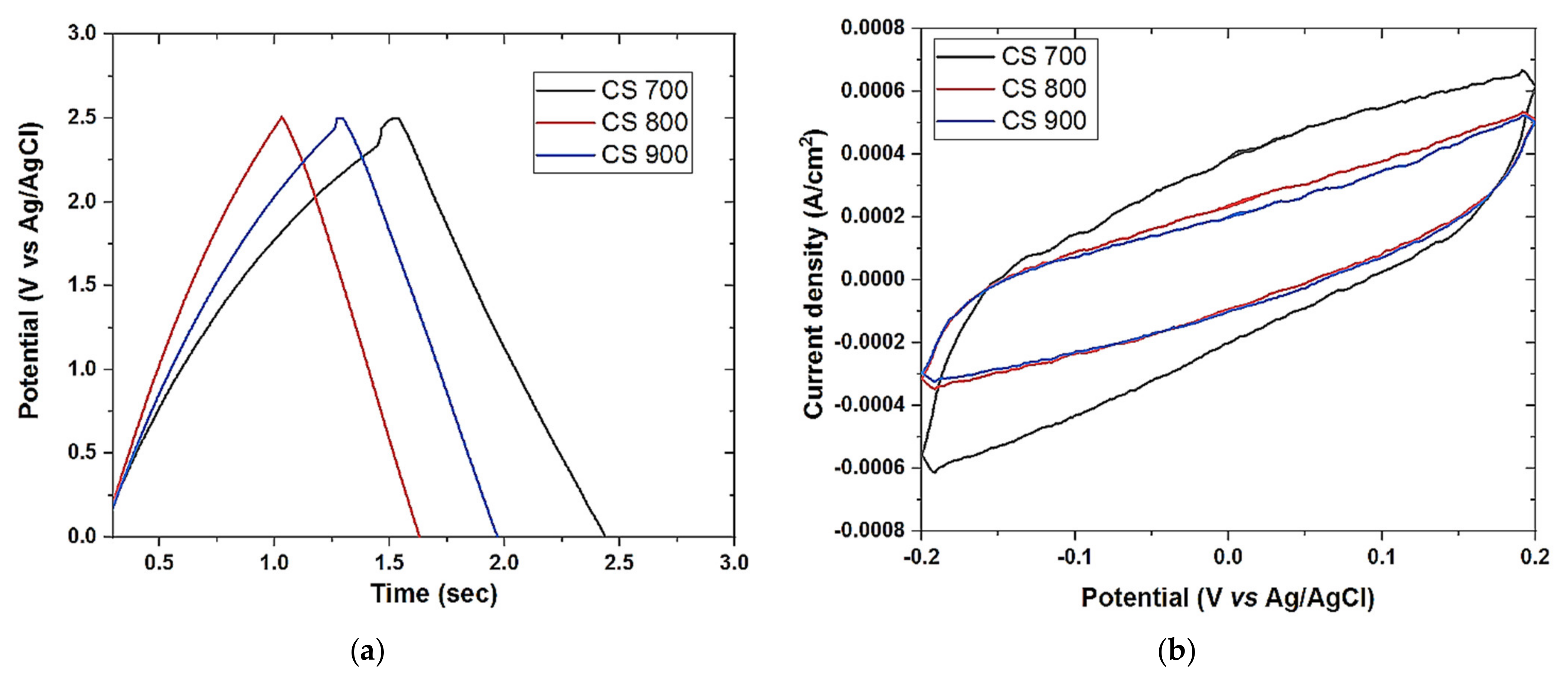
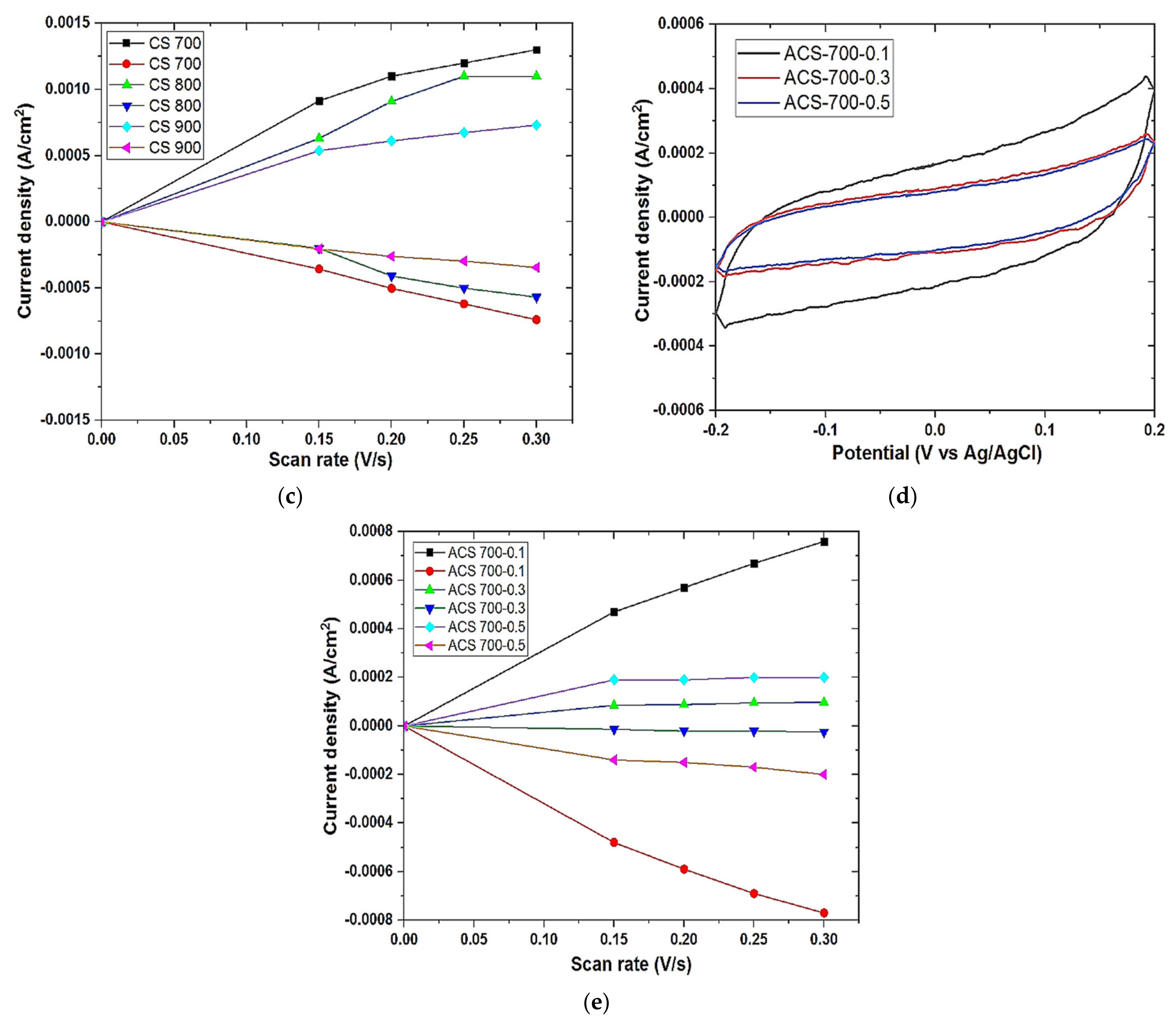
Cyclic voltammetry was also performed on Origalys Potentiostat (OGF01A, Origalys Electrochem SAS, Les Verchères 2, France) using a three-electrode system as described above at an operating window of −0.4 to 0.8 V vs. ref (0.1 V Ag/AgCl) in a 1.0 M NaCl electrolyte. The double-layer capacitance (C
DL) was determined using cyclic voltammetry at different scan rates by considering the open circuit potential (OCP 0.1 V vs. ref) of the charging and the discharging currents. The determined double-layer capacitance of the system was the absolute value of the slope of the linear plot of charging current fitted to the data. Double-layer capacitance (C
DL) is calculated using Equation (1) below
For an ideal capacitor Q = CV, thus by differentiation i = C v, where v is the scan rate.
The double-layer charging current i is equal to the product of the scan rate, v, and the electrochemical double-layer capacitance, CDL.
Galvanostat charge discharge (GCD) was also performed on the same system described above at a current density of 0.1 A/g.


 ,
, 


