Article

Measurement of the Diffusion Coefficient of Xenon in Self-Sintered Nanopore Graphite for Molten Salt Reactor

1
Shanghai Institute of Applied Physics, Chinese Academy of Sciences, Shanghai 201800, China
2
University of Chinese Academy of Sciences, Beijing 100049, China
3
School of Materials Science and Engineering, Changzhou University, Changzhou 213164, China
4
Dalian National Laboratory for Clean Energy, Dalian 116023, China
5
Key Laboratory of Carbon Materials, Institute of Coal Chemistry, Chinese Academy of Sciences, Taiyuan 030001, China
6
Beijing High-Tech Institute, Beijing 100094, China
*
Authors to whom correspondence should be addressed.
These authors contributed equally to this work.
Submission received: 27 September 2023 / Revised: 10 November 2023 / Accepted: 15 November 2023 / Published: 22 November 2023
(This article belongs to the Special Issue High-Performance Carbon Materials and Their Composites)

Abstract

:
The economics and safety of reactors can be affected by the diffusion of fission products into graphite. Xenon (Xe) fission products diffusing into graphite is the most critical neutron absorber and poison that can slow down or stop the chain reaction. The transport parameters for inhibiting the xenon diffusion in graphite are therefore an important scientific problem. Self-sintered nanopore-isotropic (~40 nm) graphite (SSNG) derived from green pitch coke can decrease Xe diffusion into graphite. In this study, the surface morphology and microstructural evolution in graphite before and after irradiation, as well as after annealing, were studied with different characterization methods. A method for the measurement of diffusion coefficients of fission products’ diffusion in graphite using Rutherford backscattering spectrometry (RBS) was also reported. The SSNG substrates were implanted with Xe at a dose of 4.8 × 10¹⁵ ions/cm2 and energy of 7 MeV. The RT-implanted samples were annealed in a vacuum at 650 °C for 9 h. The implanted and annealed samples were characterized using RBS. The diffusion coefficient D (Xe, 650 °C) was 6.49 × 10⁻²⁰ m2/s. The results indicate SSNG’s excellent ability to inhibit Xe diffusion and are significant for designing and evaluating the safety of nuclear reactors.

Graphical Abstract

1. Introduction

Graphite in molten salt reactors (MSRs) acts as a moderator/reflector, structural material, and accommodation for fission products (FPs). The LiF-BeF2-UF4-ThF4 fuel salt in MSRs serves as both a heat transfer storage medium and a fuel carrier. The salt is located in the same circuit and is in direct contact with graphite. As a result, decay reactions of fission products occur throughout the primary loop as well. Some of these fission products are gaseous and cause the mixture to form bubbles in the fluid [1,2]. Most of the gaseous fission products are noble gases that bubble out of the fuel salt mixture. The large neutron absorption cross-section of the 135Xe isotope diffusing into the graphite reduces the neutron economy and multiplication capability of the reactor [3,4]. In addition to this, the graphite dust containing FPs entering the main circuit and causing localized ultra-high temperatures poses a fatal threat to the operational stability and safety of the reactor and poses a major challenge to nuclear graphite reprocessing, decommissioning, etc. Prior studies indicated that graphite with pore diameters of less than 100 nm could effectively prevent the liquid fluoride salt and Xe135 penetration.
A series of graphite with pore sizes below 100 nm was prepared by our research group. In particular, self-sintered nanopore-isotropic graphite (SSNG) prepared from green pitch coke using the isostatic pressing method has a high graphitization degree and good irradiation properties [5,6], with potential for use in MSRs. However, the diffusion behavior of implanted Xe in SSNG has not been investigated. To the best of our knowledge, there are almost no reports on the diffusion coefficient of xenon in nanoporous graphite. Gaining a comprehensive understanding of the interactions between FPs and graphite, especially the diffusion behavior of xenon (Xe135-based) in graphite, is important to guide the design of MSRs.
This study investigated the diffusion behavior of Xe26+ in the SSNG for the first time. The microstructure and defect changes of SSNG before and after irradiation, as well as after annealing, were investigated using scanning electron microscopy (SEM), X-ray diffraction (XRD), and Raman spectroscopy. The diffusion coefficient of xenon ions in nanoporous graphite (~40 nm) was calculated using Rutherford backscattering spectroscopy (RBS). The implanted SSNG samples were subjected to high-temperature diffusion experiments at the MSR operating temperature (650 °C), and the experimental diffusion data of practical significance were measured.

2. Materials and Methods

2.1. Specimen Preparation and Irradiation

The green pitch coke was produced using a pressure-assisted semi-carbonization process. The as-prepared green coke blocks were subsequently wet ground in a ball mill to obtain a powder with an average size of 2.5 μm to ensure sufficient sintering activity. The slurry was then dried at 100 °C for about 3 h to completely remove the solvent before being pulverized again in a mill to obtain the desired powder. These powders were then molded into green bodies through isostatic compaction under a pressure of 100 MPa at room temperature. Subsequently, the green bodies were carbonized in a nitrogen atmosphere at a heating rate of 20 °C/min, reaching a temperature of 1000 °C and maintaining it for 2 h. Finally, the graphitization treatment was conducted under argon at temperatures up to 2600 °C, with a heating rate of 50 °C/h. Then, the self-sintered nanopore-isotropic (~40 nm) graphite (SSNG) was prepared.
The SSNG specimens were cut into 5.0 × 5.0 × 1.0 mm3 pieces for Xe26+ irradiation. All samples were polished and ultrasonically cleaned before irradiation. The samples were irradiated at room temperature using 7 MeV Xe26+ ion beams with a fluence of 4.8 × 10¹⁵ ions/cm2 on a terminal of the 320 kV high-voltage experimental platform equipped with an electron cyclotron resonance ion source in the Institute of Modern Physics, Chinese Academy of Science. To give an overall understanding of the ion irradiation behavior in the graphite bulk, the ion irradiation process was simulated using Stopping and Range of Ions in Matter (SRIM). The type of calculation chosen was “Ion distribution and Quick Calculation of Damage” [7]. A reference graphite compound (ICRU-906) was selected. The value of displacement threshold energy Ed of carbon determines the calculated number of displaced atoms. Due to the anisotropy of the graphite crystal, the displacement threshold energy Ed is not a single value. A value of 28 eV was used for the carbon atoms in the graphite material irradiated by ions [8]. The damage level (displacement per atom, dpa) was calculated using dpa = N d i s p l a c e m e n t N a t o m = Φ n d i s p l a c e m e n t ρ a t o m , where Φ, ndisplacement, and ρatom are the ion fluence, the number of displacements/ion/unit depth (calculated by SRIM 2008), and the atomic density, respectively [9]. According to the calculation of SRIM, the irradiation depth was about 2.9 µm, and the irradiation damage reached the maximum when the depth was about 2.3 µm. The peak depth of the Xe concentration was ~2600 nm. Figure 1 presents the predictions of the Xe concentration and displacement per atom (dpa) as a function of depth (distance from the irradiated surface) for an ion fluence of 4.8 × 10¹⁵ ions/cm2.

2.2. Characterizations

The changes in the microscopic morphology of the graphite were studied with a scanning electron microscope (Carl Zeiss AG, Jena, Germany). An automated mercury porosimeter (AutoPore IV 9500, Micromeritics GmbH, Unterschleißheim, Germany) was utilized to measure the pore diameter distribution and open porosity. The XRD was measured with a Bruker D8 Advance (Micromeritics GmbH, Unterschleißheim, Germany). Raman spectroscopy (HORIBA-Jobin Yvon, Lille, French) with a wavelength of 532.0 nm was used to monitor the variations in defects. The implanted SSNG samples were loaded into quartz tubes and sealed, and then the sealed quartz tubes were placed in a muffle furnace and subjected to annealing at 650 °C for 9 h. The diffusion behavior of Xe in the SSNG due to annealing was investigated using Rutherford backscattering spectrometry (RBS) with 2 MeV He+ (CAS, Shanghai, China). An analysis current of 15 nA and a scattering angle of 165° were used with a total charge of 8 μC. The resulting RBS profiles were fitted with Gaussian line shape fitting.

3. Results and Discussion

3.1. Pore Diameter Analysis

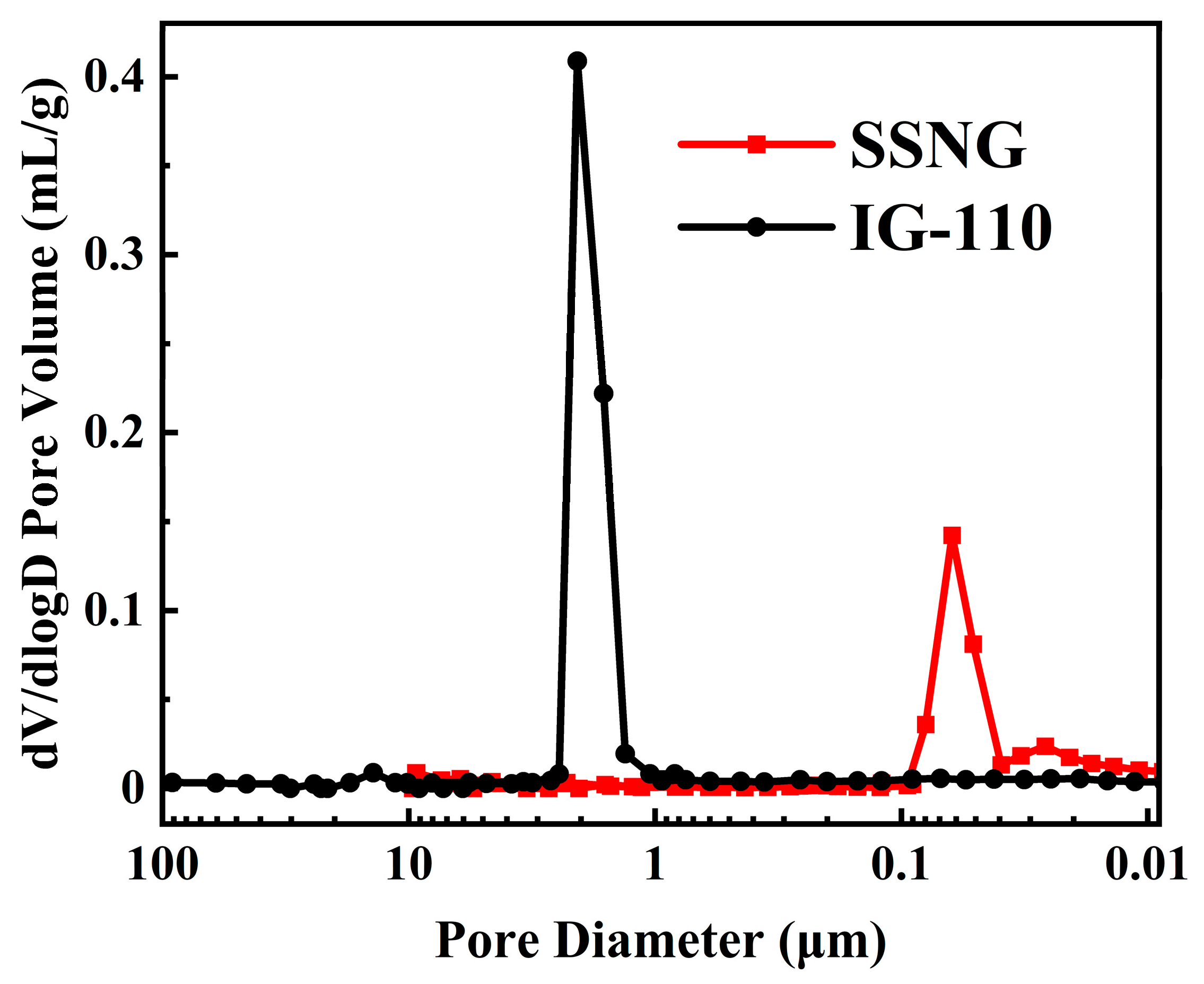
Figure 2 shows the pore size distributions of SSNG and traditional nuclear graphite IG-110. The properties of SSNG and IG-110 are given in Table 1, which clearly reveals that SSNG had a median pore diameter of 0.400 μm, which was significantly smaller compared with the 1.84 μm for IG-110. The density and open porosity of SSNG were 1.92 g/cm3 and 10%, respectively, while those of IG-110 were 1.77 g/cm3 and 18.4%, respectively. Obviously, the open porosity of SSNG was also much lower than that of IG-110. The results indicate that IG-110 was unable to inhibit the penetration of molten salt and Xe135, while SSNG could satisfy the pore size requirements (<100 nm) of MSRs. Previous molten salt infiltration experiments showed that molten salts find it very difficult to infiltrate into SSNG, even at an ambient pressure of 10 atm [5].

3.2. Microstructure Analysis

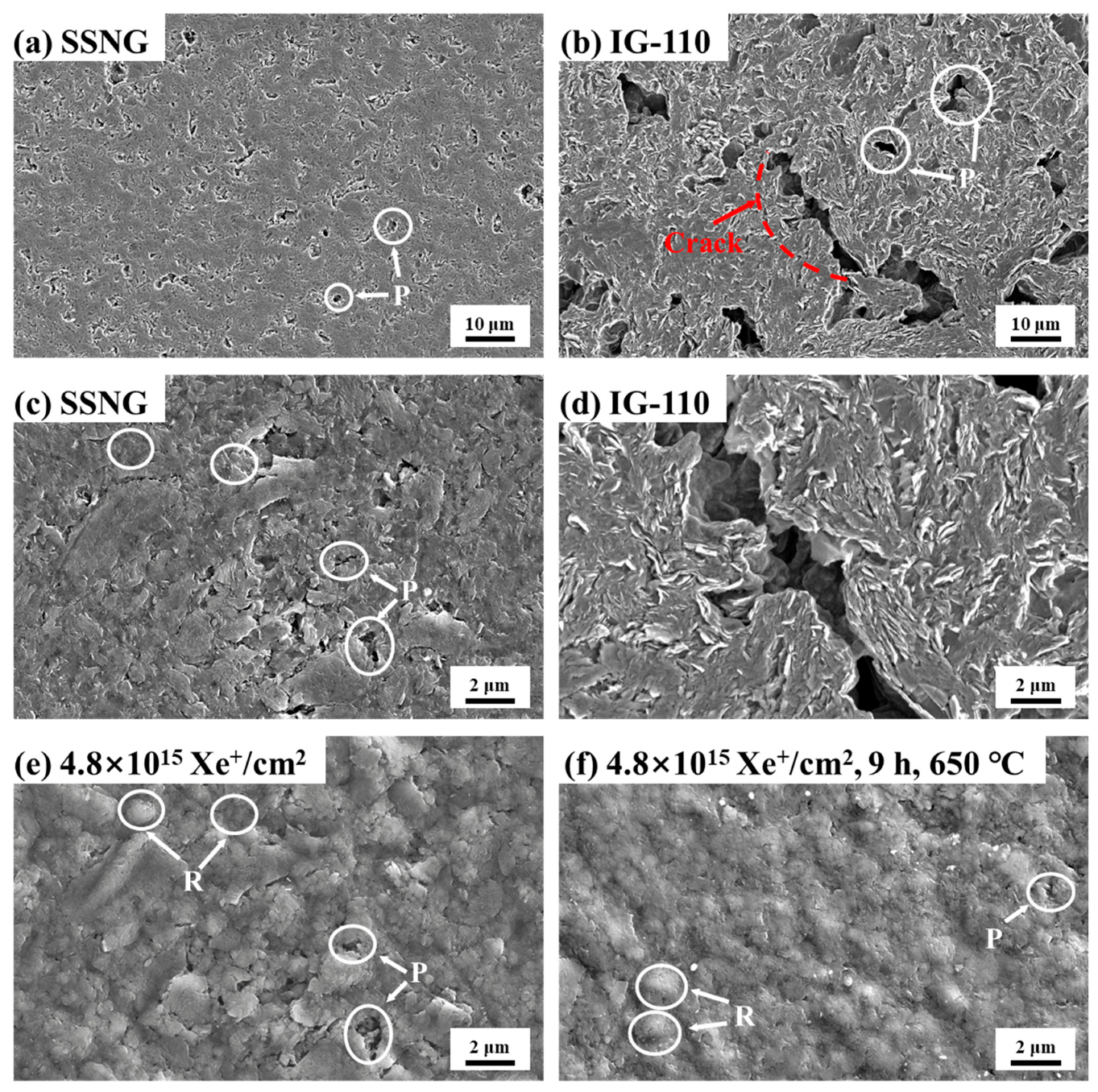
Figure 3 shows the SEM images of SSNG and IG-110. The pre-irradiation SEM images show that the obtained SSNG had a dense and homogeneous structure and exhibited a significantly smoother surface with fewer pores and almost no cracks compared with IG-110. This improvement can be attributed to the green pitch coke fillers, which had the self-sintering property and a smaller average particle size (~2.5 μm). As a result, the dense structure formed by the fillers led to a reduction in the median pore diameter and open porosity of graphite, which was consistent with the above results. After irradiation, a “Ridge-like” structure appeared on the surface of SSNG, as shown in Figure 3e, and most of the micropores shrank, which was related to the anisotropic swelling induced by irradiation. Additionally, the in-plane shrinkage of filler particles due to the swelling of the graphite microcrystals in the vertical direction led to an increase in the size of some micropores, but with a relatively small change. Compared with previous irradiation experiments of IG-110 [10], the surface integrity of the irradiated SSNG was better and less susceptible to the effects of irradiation, varying only within the average particle size of the filler. Figure 3f is an SEM image of the sample surface microstructure after annealing at 650 °C. During the annealing process, the surface flatness increased slightly due to the reduction in the “Ridge-like” structure. This suggests that the degree of irradiation damage in graphite was reduced by annealing, which may be related to the diffusion of interstitial atoms between the graphite planes, leading to the compounding of interstitial atoms and vacancies [11].
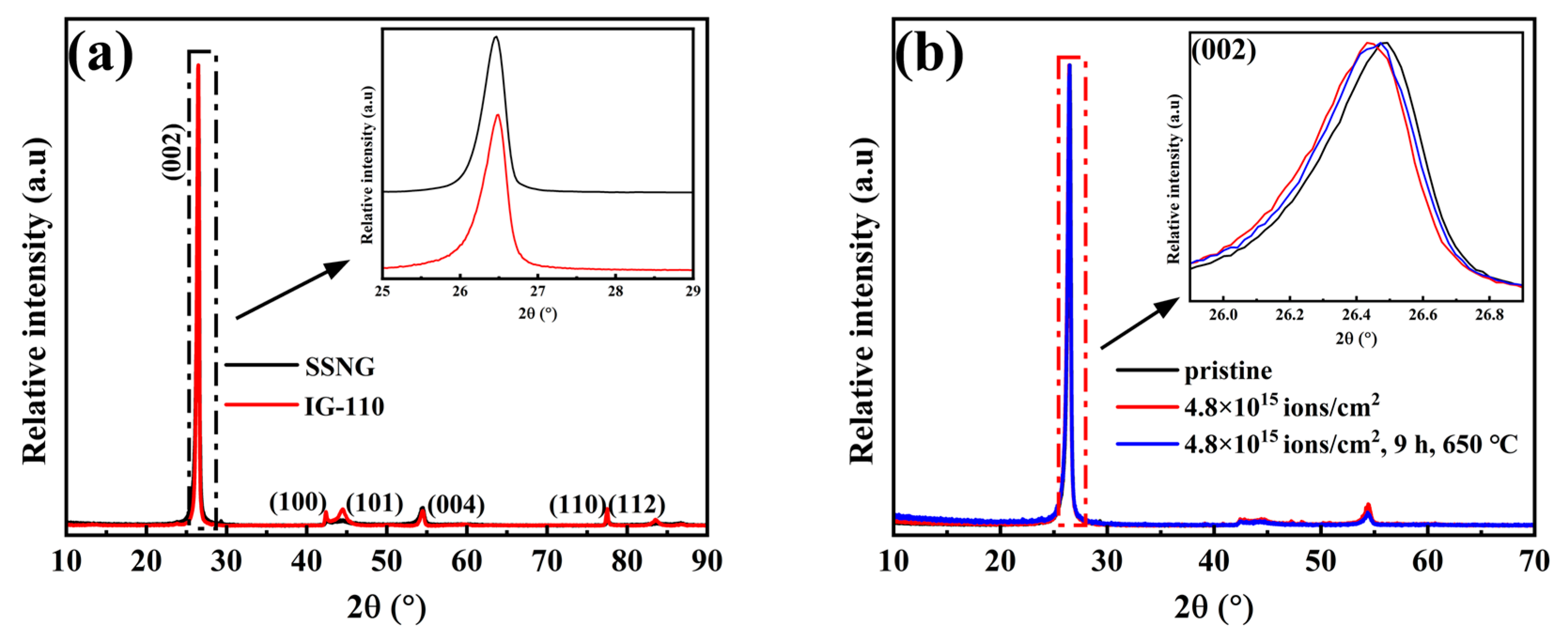
The XRD patterns of unirradiated SSNG and IG-110 are given in Figure 4a. The (002) diffraction peak of SSNG had a larger Braggs diffraction angle than that of IG-110, indicating that it had a smaller interlayer spacing and higher graphitization degree. The d002 (interlayer spacing) and the graphitization degree (g) were calculated using the following formulas [12]: d 002 = λ 2 s i n θ and g = 0.3440 d 002 0.3440 0.3354 . The d002 value for SSNG was calculated to be 0.33647 nm, which was found to be smaller than the 0.33674 nm for IG-110. Additionally, the graphitization degree of SSNG was determined to be 87.6%, whereas IG-110 had a graphitization degree of 84.2%. The differences may have been due to the different types of fillers used. The average particle size of the petroleum coke filler of IG-110 was ~20 μm, whereas that of the green pitch coke was ~2.5 μm; furthermore, the SSNG was prepared without the addition of any binder, which reduced the instability due to volatilization during the graphitization process. This observation was consistent with the SEM results. Figure 4b shows that after Xe26+ irradiation, the center of the (002) peak shifted toward the decrease in the diffraction angle, which indicates that the interlayer spacing of graphite became larger and the graphization degree of SSNG decreased. It can be seen that the defects induced by ion irradiation significantly damaged the internal lattice structure. However, the center of the (002) peak of the irradiated SSNG after annealing at 650 °C for 9 h was shifted to the larger diffraction angle, but it was still smaller than that of the pristine SSNG, indicating that the annealing caused diffusive migration of xenon ions, leading to the reduction in the layer spacing d002 of graphite, and the crystal structure was gradually restored. But the improvement of the graphite structure by the annealing had a certain limitation, and the structural damage caused by the irradiation was not eliminated. Previous studies showed that at high irradiation doses, the interstitial atoms merge to form more stable clusters (eventually forming new graphite layers), which cannot be eliminated using annealing [13].
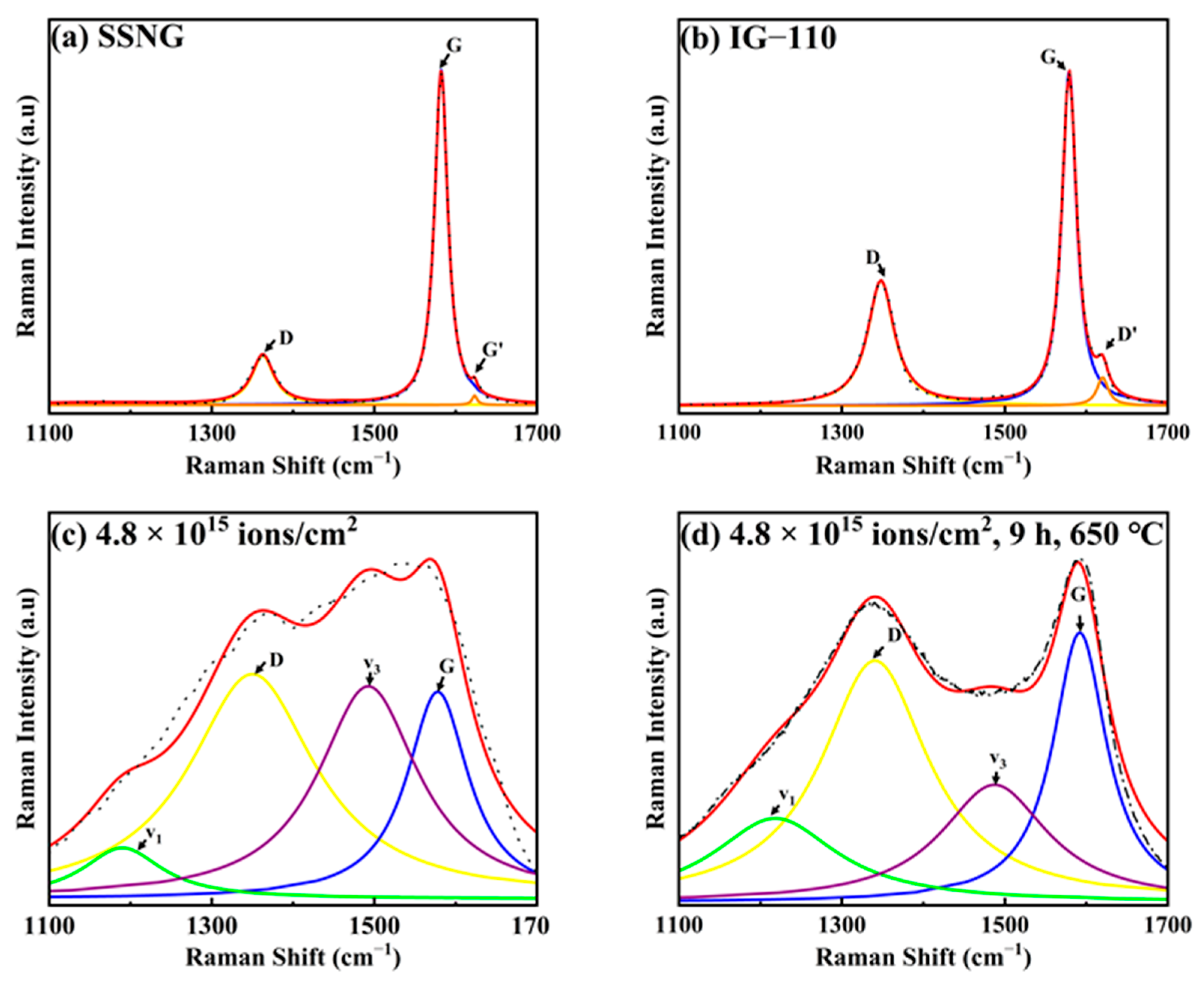
Raman spectroscopy is widely used to characterize defects in carbon materials. The Raman spectra of SSNG and IG-110 are shown in Figure 5. The intrinsic band of graphite is the G band at about 1580 cm−1, and the presence of disorder and defects is revealed using the D band at about 1350 cm−1 and the D′ band at about 1620 cm−1 [14]. The intensity ratio ID/IG is widely used to characterize the defect density in materials such as graphite. The ID/IG of SSNG was about 0.25, which was much smaller than the 0.67 of IG-110. After the xenon ion injection, the relative intensity of the D peak increased significantly, as shown in Figure 5c, and the D and G peaks almost overlapped. The ID/IG increased from 0.25 to 2.09, indicating that the defect density of the graphite increased and the ordered structure of graphite was damaged. After annealing, the profiles of the two peaks began to appear and the ID/IG decreased to 1.7, indicating that the defect concentration of the samples annealed at a high temperature was significantly reduced [15,16]. But due to the disruption of the graphite structure, the irradiation damage introduced by the higher irradiation dose could not be fully recovered by annealing, which may have been due to the fact that under high irradiation doses, interplanar defects become dominant and graphite eventually amorphizes [17], and this disordered structure is more stable and not easily changed under annealing.

3.3. Rutherford Backscattering Analysis

Rutherford backscattering spectrometry (RBS) is a highly effective elemental analysis and depth analysis technique for surface layers and thin films of solids, especially for the analysis of heavy elements on light elemental matrices [18]. This non-destructive testing method is simple to perform and widely used for determining the thickness of thin films and the relative contents of matrix elements. Due to its straightforward sample preparation, ease of operation, and reliable analytical results, RBS plays a crucial role in interdisciplinary research fields, such as materials science, microelectronics, thin film physics, and energy [19,20,21].
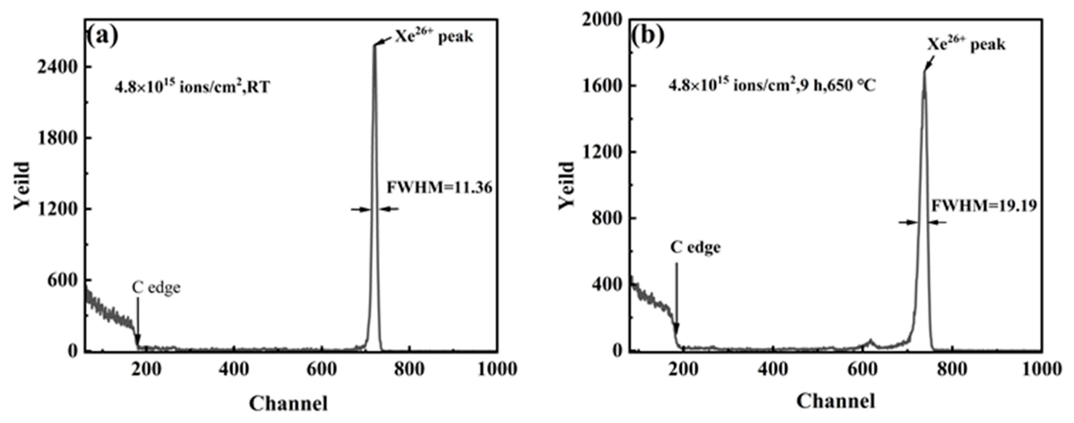
Based on the above qualitative studies, in order to further quantify the diffusion behavior of xenon in SSNG, Figure 6 shows the energy channel numbers and yields of SSNG graphite before and after isothermal annealing at 650 °C for 9 h. It can be seen that annealing the sample at 650 °C for 9 h resulted in a slight broadening of the width of the xenon profile. This broadening indicates that there was a slight loss of xenon, indicating that Xe26+ diffused after annealing at a constant temperature [22]. The diffusion model was similar to a “sandwich” structure, as shown in Figure 7. First, Xe26+ was injected into the graphite, and there was a Xe26+ residence layer under a range of depths, and the peak depth of the Xe concentration can be seen in Figure 1. The irradiation effect in graphite is the result of displacement damage caused by the collision cascade [23]. Incident ions were distributed within a certain depth range after cascade collisions. The content at other depths on the injection side was too low compared with the peak distribution region to be detected, and the graphite injection side was considered to have almost no Xe26+ residence [18,24,25], which is the model for determining the diffusion coefficient using ion injection [26], and the diffusion coefficient was obtained using the change in Xe26+ residence layer thickness before and after annealing. Therefore, the diffusion coefficient D could be obtained directly from the data of the half-height width (FWHM) of the concentration distribution peaks of Xe26+ elements in the labeled layer before and after isothermal annealing. For the FWHM values [22], the Gaussian peak function was required to fit the calculation to the distribution peaks of Xe in the RBS energy spectrum. The fitted peaks and FWHM values were obtained, and the fitting results are shown in Figure 6. The details are discussed below.
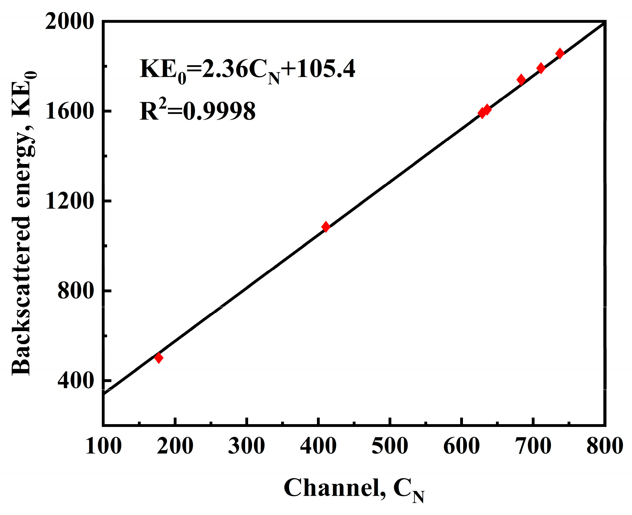
Classical Fickian diffusion kinetics and (effective) diffusion coefficients were used to simulate the diffusive migration of xenon in graphite. The (effective) diffusion coefficient elaborated upon here combined all the fundamental transport coefficients due to physical and chemical phenomena (trapping, adsorption, graphite inhomogeneities, etc.) into one parameter, which is consistent with the approach used in contemporary fuel performance modeling. The diffusion experiment assumed that the rectangular flake sample was homogeneous and did not deviate from the ideal geometry, that the concentration of xenon on the graphite surface was zero (t > 0), and that the concentration of injected xenon was determined using the half-peak width of the xenon peak in the RBS plot of the xenon ion [27]. However, to obtain the accurate diffusion coefficient, the detection system was also calibrated with the energy scale using the Si sheet coated with Au film layer to correct the energy scale of the detection system and reduce the experimental error, where the calibration spectrum is shown in Figure 8 and Figure 9. The linear calibration equation was obtained from Equations (9) and (10): KE0 = CAN + B. The energy scale parameters of the 2 MeV (4He+) detector were obtained from the relationship between the energy channel number and the kinematic factor of the calibration samples, such as Au, Si, and C, in Table 2: A = 2.36 keV/ch and B = 105.4 keV. Then, the relationship between the channel number and concentration of xenon, i.e., the relationship between energy and concentration, was converted. After obtaining the thickness of the injected xenon ion layer by blocking the cross-section factor, the diffusion coefficient of xenon was calculated using the diffusion equation, and the diffusion coefficient of Xe26+ at 650 °C was calculated to be D (Xe, 650 °C) = 6.49 × 10⁻²⁰ m2/s using the method described in Ref [26].
The mathematical model of isotropic material diffusion in this study was based on the assumption that the rate of transfer of diffusing material per unit area through the cross-section was proportional to the measured concentration gradient perpendicular to the cross-section [28]:
F = D C x
In Equation (1), F is the transfer rate through the unit area, C is the concentration of the diffusing substance (Xe26+), D is the diffusion coefficient, and x is the spatial coordinate measured perpendicular to the cross-section. Equation (1) is known as Fick’s first law of diffusion. Fick’s second law of diffusion needed to be coupled with the first law to obtain the diffusion solution for this study. Assume a rectangular strip of unit cross-sectional area with the x-axis passing through the center. Its dimensions are shown in Figure 10.
Suppose that at the center of the rectangular bar, i.e., P (x, y, z), the concentration of the substance is C. The mass of the diffuser entering the rectangular bar in the x-dx plane through the ABCD plane is
4 d y d z F x F x x d x
where Fx is the transfer rate through the corresponding plane per unit area P. The amount of diffusive material lost through face A1B1C1D1 is
4 d y d z F x + F x x d x
The increase in diffusible material in the cell can be given using Equation (7):
8 d x d y d z C t
If the total amount of incoming diffusion material is equal to the increase in the diffusion material in the cell and the diffusion is one-dimensional, i.e., the concentration gradient is only in the x-direction, Fick’s first law can be substituted in:
C t = D 2 C x 2
Equation (5) is known as Fick’s second law. The quantitative measurement of the rate at which a diffusion process occurs is expressed as a diffusion coefficient. For a one-dimensional diffusion process, the diffusion coefficient can be defined as the rate of transfer of the diffusing substance within a segment of units, divided by the spatial gradient of the concentration at that segment. If the rectangular bars in Figure 1 represent SSNG graphite specimens implanted with Xe26+, Equation (5) can be solved using Equation (6) [29]:
C x , t = 2 π D t 1 2 1 0 C 0 y e y x 2 4 D t + e y x 2 4 D t d y
In Equation (6), C is the concentration of Xe26+ and t is time. When time t = 0, C0(x) = C(x,0) represents the initial xenon profile (i.e., the xenon profile before diffusion occurs). The profile measurement at t = 0 can be approximated using Equation (7) [30]:
C 0 x = K π Dt 0 1 2 e x 2 4 D t 0
In Equation (7), K and t0 are adjustable constants. Using the boundary condition lim x 0 d d x C x , t = 0 , Equations (6) and (7) can be simplified to give Equation (8) [29]:
C x , t = K π D t + t 0 1 2 E X 2 4 D t 0 + 4 D t
If a profile W(t) is defined in such a way that C W , t = 1 2 C 0 , t , then Equation (8) becomes Equation (9) [24,31]:
W t 2 = 4 D t l n 2 + W 0 2
Equation (9) can be used to obtain the diffusion coefficient D. A plot of W t 2 versus t yields the diffusion coefficient (slope). The diffusion coefficient can be obtained by determining the slope 4Dln(2) of the unitary primary function, and W t 2 is determined using the FWHM of the Xe26+ peak. To obtain the activation energy E, the Arrhenius equation can be used [32]:
D = D 0 exp E a R T
In Equation (10), D is the diffusion coefficient, D0 is the pre-exponential factor, E is the activation energy, T is the absolute temperature, and k is the gas constant.

4. Conclusions

In summary, the prepared SSNG was irradiated using Xe ions with an ion fluence of 4.8 × 10¹⁵ ions/cm2 and then subjected to annealing at 650 °C. The pore size distribution was investigated using an automated mercury porosimeter, while the changes in the microstructure were observed using SEM, XRD, and Raman spectroscopy. The diffusion coefficient of Xe diffusion in graphite was measured using RBS. The main conclusions are as follows:
(1)
The prepared SSNG (~40 nm) not only met the pore size required for a molten salt reactor but also exhibited better irradiation resistance.
(2)
Annealing had little effect on the morphology of the SSNG but restored the structure of graphite, and this restoration was limited, which may have been related to the amorphization and diffusion of ions in graphite.
(3)
The “sandwich” model was shown to be a viable method for calculating ion diffusion coefficients. The RBS energy spectrums before and after the annealing showed that the xenon peak distributions were all close to being Gaussian, which suggests that Fickian diffusion of xenon occurred within the SSNG after annealing.
(4)
The diffusion coefficient of Xe26+ in graphite was measured using RBS for the first time. The diffusion coefficient D(Xe, 650 °C) = 6.49 × 10⁻²⁰ m2/s, which showed that the nanopore graphite SSNG had an excellent ability to inhibit xenon diffusion.

Author Contributions

Conceptualization, J.S.; Methodology, Q.L. and J.S.; Software, P.L. (Pengda Li); Formal analysis, P.L. (Pengda Li), Q.L. and M.Q.; Investigation, H.Z. and M.Q.; Resources, P.L. (Pengfei Lian); Writing—original draft, P.L. (Pengda Li), Q.L. and M.Q.; Writing—review & editing, P.L. (Pengda Li); Visualization, P.L. (Pengda Li), Q.L. and H.Z.; Supervision, J.S., J.C., Q.W., Z.T. and Z.L.; Project administration, J.S.; Funding acquisition, J.S., Z.T. and Z.L.All authors have read and agreed to the published version of the manuscript.

Funding

This research was funded by the National Natural Science Foundation of China (No. 52072397, No. 12305339); Institute of Coal Chemistry, Chinese Academy of Sciences (No. SCJC-XCL202209); and DNL Cooperation Fund, CAS (DNL202012).

Data Availability Statement

The raw/processed data required to reproduce these findings cannot be shared at this time as the data also forms part of an ongoing study.

Acknowledgments

This work was financially supported by the National Natural Science Foundation of China (No. 52072397, No. 12305339); Institute of Coal Chemistry, Chinese Academy of Sciences (No. SCJC-XCL202209); and DNL Cooperation Fund, CAS (DNL202012).

Conflicts of Interest

The authors declare no conflict of interest.

References

  1. Haubenreich, P.N.; Engel, J.R. Experience with the Molten-Salt Reactor Experiment. Nucl. Appl. Technol. 1970, 8, 118–136. [Google Scholar] [CrossRef]
  2. Price, T.; Chvala, O.; Bereznai, G. A dynamic model of xenon behavior in the Molten Salt Reactor Experiment. Ann. Nucl. Energy 2020, 144, 107535. [Google Scholar] [CrossRef]
  3. Scott, D.; Eatherly, W.P. Graphite and Xenon Behavior and their Influence on Molten-Salt Reactor Design. Nucl. Appl. Technol. 1970, 8, 179–189. [Google Scholar] [CrossRef]
  4. Dunkle, N.; Chvala, O. Effect of xenon removal rate on load following in high power thermal spectrum Molten-Salt Reactors (MSRs). Nucl. Eng. Des. 2023, 409, 112329. [Google Scholar] [CrossRef]
  5. Zhao, H.C.; He, Z.; Liu, Z.J.; Song, J.L.; Tsang, D.K.L.; Zhang, H.Y. Self-sintered nanopore-isotropic graphite derived from green pitch coke for application in molten salt nuclear reactor. Ann. Nucl. Energy 2019, 131, 412–416. [Google Scholar] [CrossRef]
  6. Zhang, H.Y.; Song, J.L.; Tang, Z.F.; He, Z.; Liu, X.D. The surface topography and microstructure of self-sintered nanopore graphite by Xe ions irradiation. Appl. Surf. Sci. 2020, 515, 146022. [Google Scholar] [CrossRef]
  7. Zhao, Y.M.; Lv, S.S.; Gao, J.; Zhou, Z.; Yeli, G.M.; Li, Z.C. Microstructure and defect evolution of nuclear graphite under temperature-dependent ion irradiation. J. Nucl. Mater. 2023, 577, 154308. [Google Scholar] [CrossRef]
  8. Zhu, Y.Q.; He, Z.T.; Ma, H.L.; Liu, F.G.; Theodosiou, A.; Smith, A.; Jones, A.; Marsden, B.; Zhou, X.T. High dose 30 MeV 58Ni5+ ion irradiation causes microstructure evolution in nuclear graphite at 400 °C. J. Nucl. Mater. 2022, 559, 153460. [Google Scholar] [CrossRef]
  9. Zhang, H.Y.; Lei, Q.T.; Song, J.L.; Liu, M.; Zhang, C.; Gao, Y.T.; Zhang, W.T.; Xia, H.H.; Liu, X.D. Direct characterization of ion implanted nanopore pyrolytic graphite coatings for molten salt nuclear reactors. RSC Adv. 2018, 8, 33927–33938. [Google Scholar] [CrossRef]
  10. Zhang, H.Y.; Cheng, J.X.; Song, J.L.; Yin, H.Q.; Tang, Z.F.; Liu, Z.J.; Liu, X.D. Topography changes and microstructural evolution of nuclear graphite (IG-110) induced by Xe26+ irradiation. New Carbon Mater. 2023, 38, 393–402. [Google Scholar] [CrossRef]
  11. Lv, S.S.; Gao, J.; Jin, Y.H.; Zhou, Z.; Zhao, Y.M.; Yano, T.; Li, Z.C. The structure evolution in neutron-Irradiated nuclear graphite and post-annealing. Radiat. Phys. Chem. 2022, 197, 110156. [Google Scholar] [CrossRef]
  12. Houska, C.R.; Warren, B.E. X-ray Study of the Graphitization of Carbon Black. J. Appl. Phys. 1954, 25, 1503–1509. [Google Scholar] [CrossRef]
  13. Burchell, T.D.; Pappano, P.J.; Strizak, J.P. A study of the annealing behavior of neutron irradiated graphite. Carbon 2011, 49, 3–10. [Google Scholar] [CrossRef]
  14. Mathew, S.; Chan, T.K.; Zhan, D.; Gopinadhan, K.; Barman, A.R.; Breese, M.B.H.; Dhar, S.; Shen, Z.X.; Venkatesan, T.; Thong, J.T.L. The effect of layer number and substrate on the stability of graphene under MeV proton beam irradiation. Carbon 2011, 49, 1720–1726. [Google Scholar] [CrossRef]
  15. Odutemowo, O.S.; Malherbe, J.B.; Prinsloo, L.; Langa, D.F.; Wendler, E. High temperature annealing studies of strontium ion implanted glassy carbon. Nucl. Instrum. Methods Phys. Res. Sect. B—Beam Interact. Mater. At. 2016, 371, 332–335. [Google Scholar] [CrossRef]
  16. Lasithiotakis, M.; Marsden, B.J.; Marrow, T.J. Annealing of ion irradiation damage in nuclear graphite. J. Nucl. Mater. 2013, 434, 334–346. [Google Scholar] [CrossRef]
  17. Niwase, K.; Tanabe, T.; Tanaka, I. Annealing experiment of ion-irradiated graphite by laser Raman spectroscopy. J. Nucl. Mater. 1992, 191, 335–339. [Google Scholar] [CrossRef]
  18. Adeojo, S.A.; Malherbe, J.B.; Njoroge, E.G.; Mlambo, M.; Odutemowo, O.S.; Thabethe, T.T.; Abdalla, Z.A.Y.; Hlatshwayo, T.T. Effect of sequential isochronal annealing on the structure and migration behaviour of selenium-ion implanted in glassy carbon. Vacuum 2020, 182, 109689. [Google Scholar] [CrossRef]
  19. Laricchiuta, G.; Vandervorst, W.; Meersschaut, J. High-sensitivity Rutherford backscattering spectrometry employing an analyzing magnet and silicon strip detector. Nucl. Instrum. Methods Phys. Res. Sect. B—Beam Interact. Mater. At. 2019, 439, 59–63. [Google Scholar] [CrossRef]
  20. Qi, M.B.; Lian, P.F.; Li, P.D.; Zhang, H.Y.; Cheng, J.X.; Wang, Q.B.; Tang, Z.F.; Pan, T.J.; Song, J.L.; Liu, Z.J. Diffusion Behavior of Iodine in the Micro/Nano-Porous Graphite for Nuclear Reactor at High Temperature. C 2023, 9, 81. [Google Scholar] [CrossRef]
  21. Gao, J.; Huang, H.F.; Liu, J.Z.; Lei, Q.T.; Wang, C.J.; Han, Z.B.; Yang, G.; Li, Y. Helium release and lattice swelling in nickel foil irradiated by multiply-energy helium ions. Nucl. Instrum. Methods Phys. Res. Sect. B—Beam Interact. Mater. At. 2019, 450, 108–113. [Google Scholar] [CrossRef]
  22. Odutemowo, O.S.; Dhlamini, M.S.; Wendler, E.; Langa, D.F.; Ismail, M.Y.A.; Malherbe, J.B. Effect of heat treatment on the migration behaviour of Sr and Ag CO-implanted in glassy carbon. Vacuum 2020, 171, 109027. [Google Scholar] [CrossRef]
  23. Christie, H.J.; Robinson, M.; Roach, D.L.; Ross, D.K.; Suarez-Martinez, I.; Marks, N.A. Simulating radiation damage cascades in graphite. Carbon 2015, 81, 105–114. [Google Scholar] [CrossRef]
  24. Hlatshwayo, T.T.; Sebitla, L.D.; Njoroge, E.G.; Mlambo, M.; Malherbe, J.B. Annealing effects on the migration of ion-implanted cadmium in glassy carbon. Nucl. Instrum. Methods Phys. Res. Sect. B—Beam Interact. Mater. At. 2017, 395, 34–38. [Google Scholar] [CrossRef]
  25. Odutemowo, O.S.; Malherbe, J.B.; Limbach, R.; Wondraczek, L.; Wendler, E.; Undisz, A.; Njoroge, E.G.; Idisi, D.O.; Dhlamini, M.S. Changes in the mechanical, structural and electrical properties of glassy carbon due to strontium and silver co-implantation and annealing. Appl. Surf. Sci. 2021, 537, 147929. [Google Scholar] [CrossRef]
  26. Malherbe, J.B.; Selyshchev, P.A.; Odutemowo, O.S.; Theron, C.C.; Njoroge, E.G.; Langa, D.F.; Hlatshwayo, T.T. Diffusion of a mono-energetic implanted species with a Gaussian profile. Nucl. Instrum. Methods Phys. Res. Sect. B—Beam Interact. Mater. At. 2017, 406, 708–713. [Google Scholar] [CrossRef]
  27. Malherbe, J.B.; Odutemowo, O.S. Diffusion and segregation of Sr in glassy carbon: Model and analysis. Diam. Relat. Mater. 2021, 120, 108709. [Google Scholar] [CrossRef]
  28. Mukhawana, M.B.; Theron, C.C.; Malherbe, J.B.; van der Berg, N.G.; Botha, A.J.; Grote, W.; Wendler, E.; Wesch, W.; Chakraborty, P. Behavior of iodine implanted in highly oriented pyrolytic graphite (HOPG) after heat treatment. Nucl. Instrum. Methods Phys. Res. Sect. B—Beam Interact. Mater. At. 2012, 273, 65–67. [Google Scholar] [CrossRef]
  29. Myers, S.M.; Picraux, S.T.; Prevender, T.S. Study of Cu diffusion in Be using ion backscattering. Phys. Rev. B 1974, 9, 3953–3964. [Google Scholar] [CrossRef]
  30. Friedland, E.; van der Berg, N.G.; Malherbe, J.B.; Hancke, J.J.; Barry, J.; Wendler, E.; Wesch, W. Investigation of silver and iodine transport through silicon carbide layers prepared for nuclear fuel element cladding. J. Nucl. Mater. 2011, 410, 24–31. [Google Scholar] [CrossRef]
  31. Rocchini, M.; Chiari, M.; Pasquali, E.; Nannini, A.; Hadyńska-Klęk, K.; Sona, P.; Bazzacco, D.; Benzoni, G.; Camera, F.; Czelusniak, C.; et al. Applications of Rutherford backscattering analysis methods to nuclear physics experiments. Nucl. Instrum. Methods Phys. Res. Sect. B—Beam Interact. Mater. At. 2021, 486, 68–72. [Google Scholar] [CrossRef]
  32. Murarka, S. Diffusion Barriers in Semiconductor Devices/Circuits; William Andrew Publishing: Norwich, NY, USA, 2005; pp. 239–281. [Google Scholar]
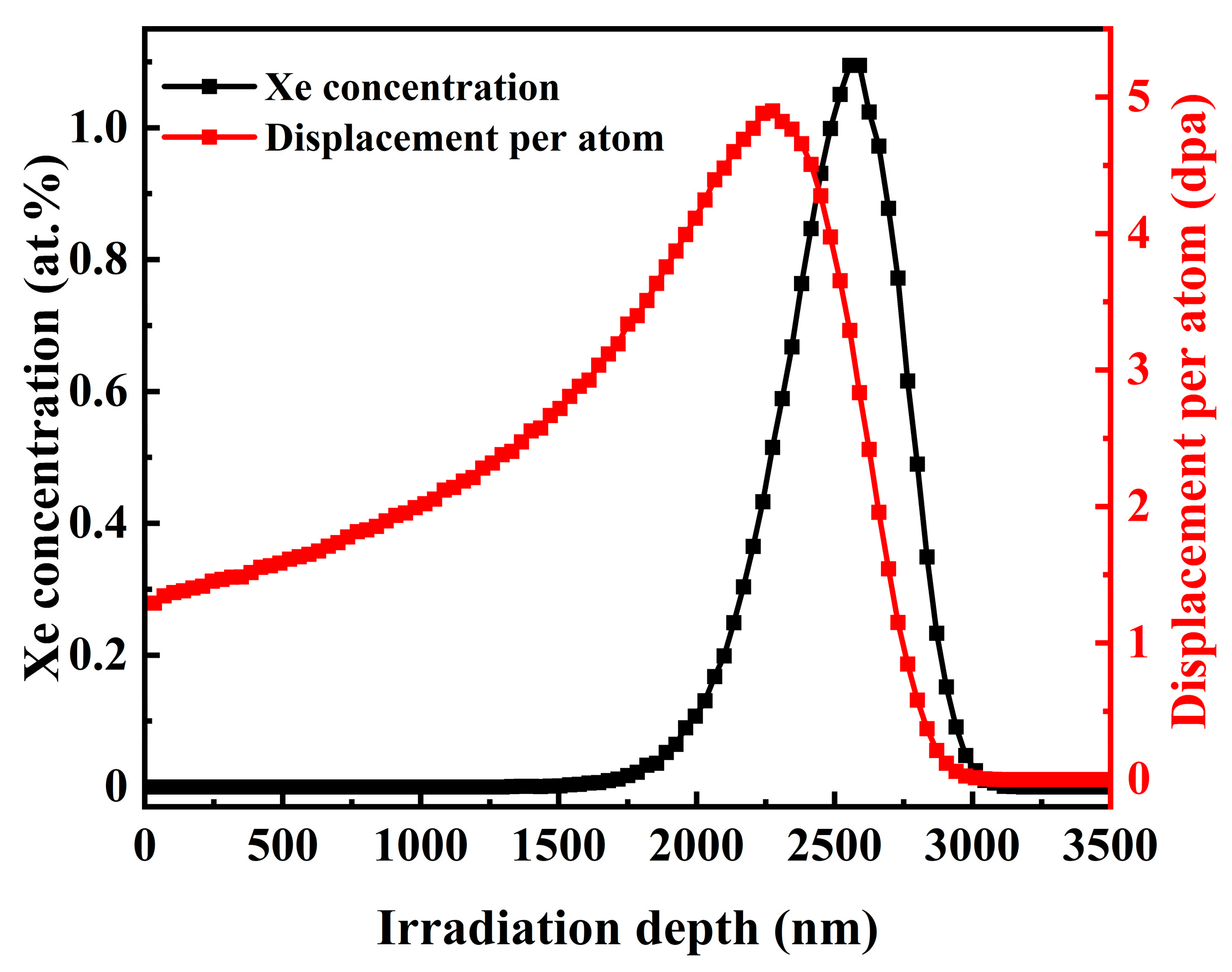
Figure 1. SRIM calculation of the Xe concentration and the displacement per atom in the graphite irradiated using 7 MeV Xe26+ with an ion fluence of 4.8 × 10¹⁵ ions/cm2.
Carbon 09 00113 g001
Figure 2. The pore size distribution of SSNG and IG-110.
Carbon 09 00113 g002
Figure 3. SEM images of SSNG: (a,c) unirradiated, (e) after 4.8 × 10¹⁵ Xe+/cm2 irradiation, (f) after annealing at 650 °C for 9 h after irradiation. (b,d) SEM images of IG-110.
Carbon 09 00113 g003
Figure 4. (a) XRD patterns of pristine SSNG and IG-110; (b) XRD patterns of SSNG before and after irradiation and after annealing at 650 °C for 9 h after irradiation, with (002) peak zoomed to show more details.
Carbon 09 00113 g004
Figure 5. Raman spectra of SSNG: (a) unirradiated, (c) after 4.8 × 10¹⁵ Xe+/cm2 irradiation, (d) after annealing at 650 °C for 9 h after irradiation. (b) Raman spectra of IG-110.
Carbon 09 00113 g005
Figure 6. Rutherford backscattering spectroscopy (RBS) spectra of (a) Xe26+ implanted into SSNG at room temperature (RT) and (b) SSNG after injection of Xe26+ and held at 650 °C for 9 h.
Carbon 09 00113 g006
Figure 7. Schematic diagram of the change in the injected layer after isothermal annealing of Xe26+ injected into SSNG: (a) after 4.8 × 10¹⁵ Xe+/cm2 irradiation, (b) after annealing at 650 °C for 9 h after irradiation.
Carbon 09 00113 g007
Figure 8. RBS spectra of Au-coated Si sheets used to calibrate the energy scale of the detection system.
Carbon 09 00113 g008
Figure 9. A calibration plot for estimating the surface position for carbon and depth profile for Xe26+ implanted in SSNG.
Carbon 09 00113 g009
Figure 10. Schematic representation of a rectangular bar used to derive Fick’s law.
Carbon 09 00113 g010
Table 1. Properties of SSNG and IG-110.
PropertiesSSNGIG-110
Bulk density (g/cm3)1.92 ± 0.021.77 ± 0.02
Open porosity (%)10.0 ± 0.118.4 ± 0.1
Median pore diameter (volume, μm)0.4001.840
Table 2. Elements and conditions used to create a surface position calibration plot (Figure 9). The kinematic factors, backscattered energy, and channel numbers for the elements are also shown.
ElementKinematic Factor/KBackscattered/E0KChannel/CNIncident Energy E0/MeV
Au0.921.8407352.000
Si0.541.0804122.000
C0.260.5201762.000
I0.891.7837112.000
Pd0.861.7206842.000
As0.811.6206422.000
Ga0.801.6006332.000
Disclaimer/Publisher’s Note: The statements, opinions and data contained in all publications are solely those of the individual author(s) and contributor(s) and not of MDPI and/or the editor(s). MDPI and/or the editor(s) disclaim responsibility for any injury to people or property resulting from any ideas, methods, instructions or products referred to in the content.