Article

Batch Fabrication of Electrospun PAN/PU Composite Separators for Safe Lithium-Ion Batteries

1
College of Textile and Engineering, Soochow University, Suzhou 215123, China
2
Jiangsu Engineering Research Center of Textile Dyeing and Printing for Energy Conservation, Discharge Reduction and Cleaner Production (ERC), Soochow University, Suzhou 215123, China
*
Author to whom correspondence should be addressed.
Batteries 2024, 10(1), 6; https://doi.org/10.3390/batteries10010006
Submission received: 27 October 2023 / Revised: 16 December 2023 / Accepted: 22 December 2023 / Published: 25 December 2023

Abstract

:
As an important element of lithium-ion batteries (LIBs), the separator plays a critical role in the safety and comprehensive performance of the battery. Electrospun nanofiber separators have a high porosity and good electrolyte affinity, which are favorable to the transference of lithium ions. In this paper, the batch preparation of polyacrylonitrile (PAN)-based nanofiber separators are obtained via spherical section free surface electrospinning (SSFSE). Introducing an appropriate amount of polyester polyurethane (PU) can effectively enhance the mechanical property of PAN nanofiber separators and help the separators resist the external force extrusion. The results show that when PAN:PU = 8:2, the porosity and electrolyte uptake rate of the composite nanofiber separator (PAN-2) are 62.9% and 643.3%, respectively, exhibiting a high ionic conductivity (1.90 mS/cm). Additionally, the coin battery assembled with PAN-2 as a separator (LiFePO4/PAN-2/lithium metal) shows good cycling performance and good rate performance, with a capacity retention rate of 93.9% after 100 cycles at 0.5 C, indicating that the battery with PAN-2 has a good application potential in advanced energy storage.

Graphical Abstract

1. Introduction

Rechargeable batteries can effectively translate chemical energy into electricity and depend on electrochemical processes to store energy. Compared with other rechargeable batteries, lithium-ion batteries (LIBs) dominate the field of chemical energy storage because of their slow self-discharge, long service life, and relatively high energy and power densities, making them widely used in various fields from portable electronic devices to electric vehicles [1,2,3]. However, the safety accidents caused by the thermal runaway of batteries have attracted widespread concerns recently. The main components of LIBs typically include cathodes, anodes, separators and electrolytes. The separator is an indispensable part of an LIB, which is located between the anode and cathode, playing a major role in the safety and comprehensive performance of LIBs. Currently, the widely used separators in commercialized LIBs are the polyolefin separators, including polypropylene (PP) and polyethylene (PE) separators, because of their low cost, superior mechanical strength, good electrochemical stability, and thermal shutdown characteristics [4,5]. However, their low porosity and poor thermal stability and wettability limit their ion conduction in LIBs, making it difficult to satisfy the needs of high-performance LIBs [6].
Currently, common approaches to improving the performance of commercial battery separators include coating modification [7,8] or selecting suitable materials to prepare composite separators via casting, phase conversion, electrospinning, freeze-drying, and so on [9,10,11,12,13]. Among these ways, electrospinning is a common method for preparing nanofiber separators, which can regulate the diameter of nanofibers. The resulting nanofiber separators have advantages such as high porosity, a unique pore structure, and excellent ionic conductivity [14]. Nevertheless, the electrospun nanofiber separators prepared via the traditional single-needle electrospinning (SNE) are limited in practical application due to their low preparation efficiency. Accordingly, multi-needle electrospinning (MNE) has been presented to increase the nanofiber yield by enhancing the number of needles [15]. Mei et al. [16] used a centrifugal electrospinning method to prepare separators, which was a rotating MNE method that could improve production efficiency, and explored the suitable inner diameter for needles. However, needle blockage is prone to occur during the MNE process, especially if the spinning solution contains particles. In order to solve this problem, free surface electrospinning (FSE) provides a way to increase the nanofiber production, where multiple jets are directly formed from the surface of the solution without the interference from the electric fields between the needles [17]. The FSE process primarily utilizes direct or other auxiliary methods (including air flow [18] or changing the nozzle morphology [19]) to make the applied electric field force overcome the surface tension of the solution, thereby generating lots of tiny protuberances analogous to Taylor cones on the surface of the solution. Afterward, these tiny protuberances produce multiple jets due to the stretching effect of the applied electric field force. Ultimately, these jets are further stretched and solidified to form a large amount of nanofibers.
Presently, the polymers used in electrospun nanofiber separators include polyacrylonitrile (PAN) [20,21,22], polyimide (PI) [23,24,25], polyvinylidene fluoride (PVDF) [26,27,28], and so on [29,30]. Among them, PAN exhibits superior thermal stability at high temperatures due to its high melting point, and its nitrile group (-CN) facilitates the dissociation of lithium ions in electrolytes [31]. Accordingly, PAN is generally applied as a base material in nanofiber separators. PAN nanofiber separators are especially promising owing to their excellent electrolyte affinity and thermal stability [32]. However, the relatively poor mechanical properties of PAN nanofiber separators limit their application in LIBs [33]. The mechanical performances of separators are crucial for resisting the high tension in battery assembly, preventing lithium dendrites from puncturing the separator and improving the safety of batteries. Accordingly, the application of PAN-based nanofiber separators in LIBs can be expanded by combining PAN with other spinnable polymers or adding various fillers [34,35]. Polyurethane (PU) is synthesized from polyisocyanate and polyols, with excellent mechanical properties including high strength and good toughness. Various LIB separators containing PU have been reported [36,37]. Tang et al. [36] used PU to prepare nanofiber separators with elevated strength and toughness for the safety of batteries, which exhibited better tensile strength than PAN separators. Chen et al. [37] used the PAN/PU nanofiber membrane as the substrate of LIB separators, which provided an outstanding mechanical strength that could meet the need for practical application in LIBs.
In our previous research [38,39,40], a series of FSE devices for the batch preparation of nanofibers were proposed to overcome the poor efficiency of SNE. Therefore, this paper presented an FSE device for the batch preparation of PAN/PU nanofiber membranes and discussed the optimal ratio of PAN and PU when they were used as LIB separators. And, the LIB assembled with the optimal separator exhibited better performances in terms of impedance, cycling and rate.

2. Materials and Methods

2.1. Raw Materials

Polyacrylonitrile (PAN, MW = 150,000) was supplied by Beijing Lark Branch Co., Ltd. (Beijing, China). Polyurethane (PU) was supplied by Yuyao Bangchao New Materials Co., Ltd. (Yuyao, China). N,N-dimethylformamide (DMF) (analytical reagent) was purchased from Shanghai Chemical Reagent Co., Ltd. (Shanghai, China). The commercialized polypropylene (PP) separator (Celgard 2400) was provided by Suzhou Shengernuo Technology Co., Ltd. (Suzhou, China). The electrolyte was 1 M solution of lithium hexafluorophosphate (LiPF6) in ethylene carbonate, dimethyl carbonate and ethylmethyl carbonate (EC + DMC + EMC, 1:1:1 by volume), supplied by Suzhou Dodo Chemical Technology Co., Ltd. (Suzhou, China).

2.2. Characterization of Spinning Solution

The solution conductivity was confirmed using a conductivity meter (DDS-307A, INESA Analytical Instrument Co., Ltd., Shanghai, China) at room temperature. The solution viscosity was determined using a digital viscometer (SNB-1, Ruifang Biotechnology Co., Ltd., Shanghai, China).

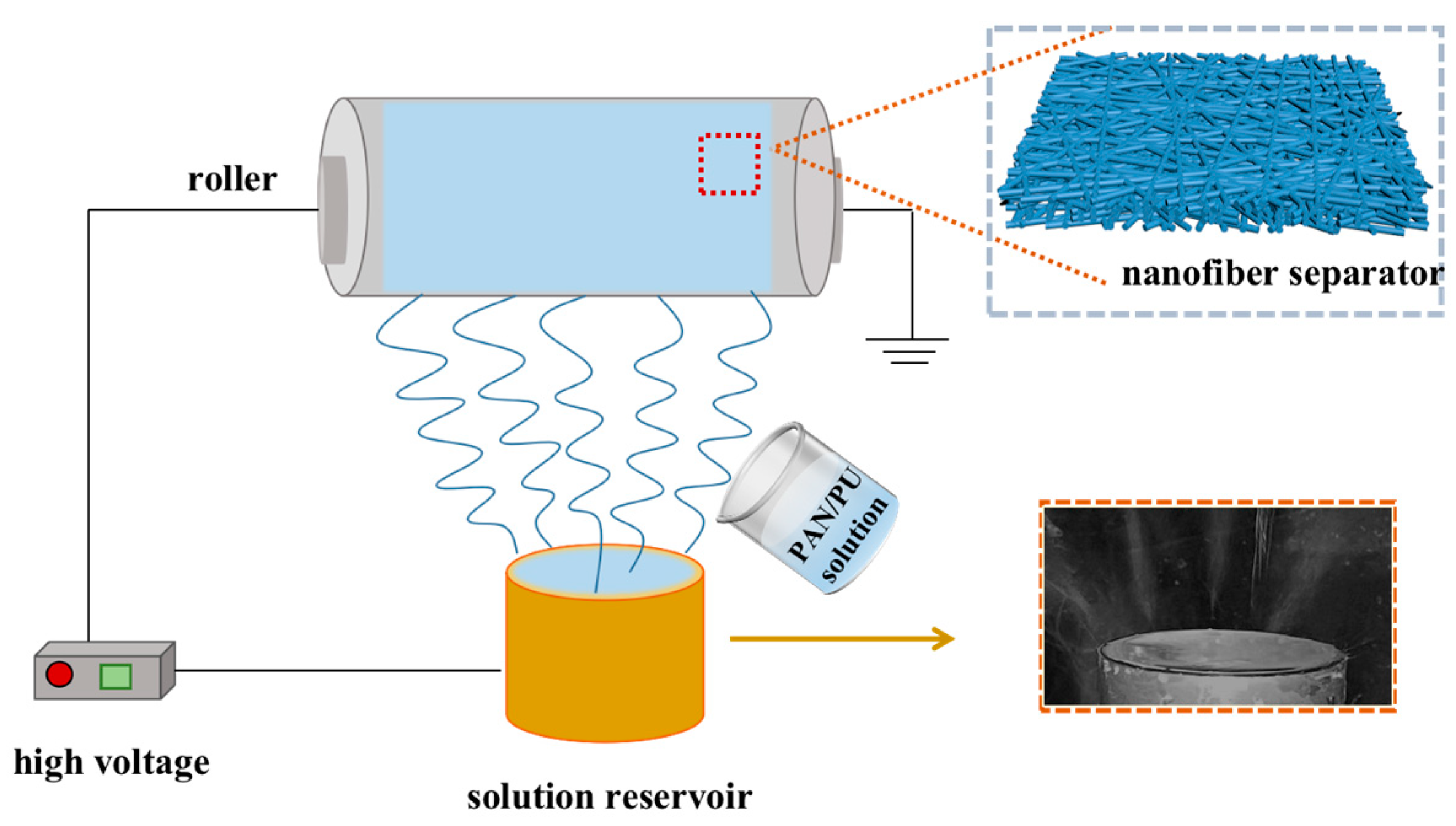
2.3. Batch Fabrication of Nanofiber Separators

As illustrated in Figure 1, the PAN/PU nanofiber membranes were fabricated in batch via a spherical section FSE (SSFSE), which were applied as LIB separators. The obtained spinning solution was added to the solution reservoir with a height of 40 mm and a diameter of 25 mm. After the high-voltage power supply was turned on, the spinning solution at the edge of the reservoir was subjected to the electric field force to overcome the surface tension of the solution and formed multiple jets according to the tip discharge theory [41]. After the solvent evaporated, nanofibers were formed and collected on a high-speed rotating roller with a length of 350 mm and a diameter of 160 mm. Under the appropriate temperature (about 25 °C) and relative humidity (about 60%), all SSFSE processes were carried out at a spinning voltage of 60 kV, a collecting distance of 220 mm and a collector rotating speed of 340 r/min.
The total solute mass fraction of the PAN/PU spinning solution using DMF as the solvent was 12 wt%, with the ratios of PAN to PU being 9:1, 8:2 and 7:3, respectively. The PAN/PU spinning solution was stirred at room temperature for 12 h until uniform. The spinning solution properties have great effects on the yield and quality of nanofibers [42]. An increase in solution viscosity can enhance the fiber diameter and yield, while an increase in solution conductivity can reduce the fiber diameter and improve the fiber yield [43]. The viscosity and conductivity of these three spinning solutions were measured, as shown in Table 1. The nanofiber separators obtained via electrospinning PAN/PU solutions with the ratios of 9:1, 8:2 and 7:3 were named as PAN-1, PAN-2 and PAN-3, respectively. The yields of nanofiber separators were measured via a precise electronic balance after electrospinning for 30 min under a stable spinning condition. And, the measurement was repeated five times to obtain an average value. As displayed in Figure 2a, the yield of PAN, PAN-1, PAN-2 and PAN-2 reached 6,09, 5.49, 2.4 and 1.71 g/h, respectively, which indicated that using SSFSE could efficiently prepare nanofiber separators, with a yield hundreds of times higher than that of SNE. In addition, the yield of electrospun nanofiber separators decreased with the increase in PU content owing to the decrease in the viscosity and conductivity of the spinning solution [44].

2.4. Characterization of Nanofiber Separators

The morphology of nanofiber separators was surveyed through scanning electron microscopy (SEM, Regulus8100 and Hitachi S4800, Hitachi, Tokyo, Japan). In total, 5 SEM images and 20 nanofibers in each SEM image were chosen randomly for nanofiber diameter distribution analysis through ImageJ software (v1.54h).
The weight difference of the separator before and after soaking in n-butanol for 2 h can reflect its porosity (P), which is calculated according to Formula (1), which is as follows:
P = m T m s ρ 1 × π R 2 × h × 100 %
where  m T  is the mass of the separator after absorbing n-butanol,  m s  is the dry mass of the separator,  ρ 1  is the density of n-butanol (0.81 g/cm3),  R  is the radius of the separator (9.5 mm), and  h  is the thickness of the separator.
The PAN/PU membranes prepared using an SSFSE device were cut out into 40 mm × 10 mm rectangular membrane samples, and the average thickness of each sample was measured 5 times and recorded. After that, a universal material testing machine (Instron-3365) was used to test the tensile strength and elongation at break of the samples at the speed of 10 mm/min. Each sample was tested 5 times to obtain the average value, and its tensile strength and elongation at break were calculated according to the following formula:
δ = P A
where  δ  is the stress of the sample membrane (MPa), P is the load (N), and  A  is the cross-sectional area of the sample membrane (mm2).
ε = L L 0 L 0 × 100 %
where  ε  is the strain of the sample membrane (%),  L  is the length of the sample after deformation (mm),  L 0  is the original standard distance length of the sample that is the clamping distance (mm), and  L L 0  is the displacement tested via the universal material testing machine (mm).
The electrolyte affinity of separators could be characterized by measuring the contact angle between the separator and the electrolyte, which was determined using a contact angle meter (Krüss DSA 100, German Cruz company, Hamburg, Germany), and the volume of each drop of electrolyte was set to 5 μL. After each sample was tested at different positions 5 times, the angle average value was obtained. In addition, the electrolyte uptake rate ( U p t a k e ) of separators was tested by soaking in them electrolyte for 2 h and calculated according to Formula (4), which is as follows:
U p t a k e = W w W d W d × 100 %
where  W w  is the weight of separator after absorbing the electrolyte, and  W d  is the dry weight of the separator.
To determine the thermal shrinkage rate of nanofiber separators, the separators with a diameter of 19 mm were heated in a constant temperature drying oven for 30 min at each temperature point, with temperature points set at 140 °C, 160 °C and 180 °C, respectively. Then, the separators were taken out and their sizes before and after heating were measured with a ruler, and the thermal shrinkage rate ( S ) of separators was calculated according to Formula (5), which is as follows:
S = D 1 D 2 D 1 × 100 %
where  D 1  is the separator diameter at room temperature (19 mm), and  D 2  is the minimum diameter of the separator after thermal treatment for 30 min.

2.5. Battery Assembly

Preparation of LiFePO4 cathode: PVDF, carbon black and LiFePO4 were added to the N-methyl pyrrolidone (NMP) solvent in that respective order, stirred for 2 h after adding the previous two, and then stirred for 8–10 h after adding LiFePO4. Subsequently, the slurry was coated onto an aluminum foil and dried for 12 h at 110 °C. The mass-loading LiFePO4 of the LiFePO4 cathode was 2 mg/cm2.
The battery shells were ultrasonically cleaned twice with ethanol and dried at 60 °C before being taken into a glove box filled with argon (both the O2 and H2O content were less than 0.01 ppm). All composite PAN/PU separators and LiFePO4 cathodes were dried for half an hour to remove moisture before assembly.

2.6. Electrochemical Tests

Ion conductivity can characterize the ability of separators to allow lithium ions to pass through. For measuring the ionic conductivity of separators, a separator was placed between two stainless steel (SS) electrodes. Specifically, after placing the separator on one SS, 60 μL of electrolyte was added to completely infiltrate the separator, and the other SS was placed on it. Then, an electrochemical workstation (SP-300, Bio-Logic company, Seyssinet-Pariset, France) was applied to test the battery (SS/separator/SS battery) using the alternating current (AC) impedance method. The AC impedance spectra of batteries were determined with a frequency range from 1 to 106 Hz at an amplitude of 5 mV. And, the ionic conductivity of separators ( δ ) could be determined using Formula (6), which is as follows:
δ = L R b × A
where  L  is the separator thickness (cm),  R b  represents the bulk resistance of the separator confirmed from the Nyquist plot of an AC impedance spectrum (Ω), and  A  is the area of the SS electrode (1.6 × 1.6 cm2), respectively.
For measuring the lithium-ion transference number of the separators, a coin battery with lithium metal (LM) as the electrodes (LM/separator/LM battery) was assembled according to the above method, and then it was tested via the electrochemical workstation (SP-300) with a polarization voltage ( Δ V ) of 10 mV. Afterward, the lithium-ion transference numbers ( t L i + ) of different separators were confirmed according to Formula (7), which is as follows:
t L i + = I S Δ V I 0 R 0 I 0 Δ V I S R S
where  Δ V  is the polarization potential ( Δ V  = 10 mV)  I 0  and  I S  are the onset and stable currents, respectively, during the polarization process, and  R 0  and  R S  are the migration resistance of batteries before and after polarization, respectively.
The electrochemical stability of separators was characterized using a linear scanning voltammetry (LSV) test. Based on the coin battery assembled with SS as the working electrode and LM as the counter electrode (SS/separator/LM battery), the LSV tests were carried out using the electrochemical workstation (SP-300) at a scanning rate of 1 mV/s within the range of 0–6 V at room temperature.
The charge–discharge cycling performance of LiFePO4/separator/LM batteries was conducted using a battery testing system (CT-4008T-5V10Ma-164, Shenzhen Xinwei Electronics Co., Ltd., Shenzhen, China) with a potential window of 2.5–4.2 V at 0.5 C.
In order to confirm the rate capability of the LiFePO4/separator/LM battery, the battery was charged to 4.2 V and discharged to 2.5 V from 0.1 C, 0.2 C, 0.5 C, 1 C to 2 C and then back to 0.2 C at room temperature.

3. Results

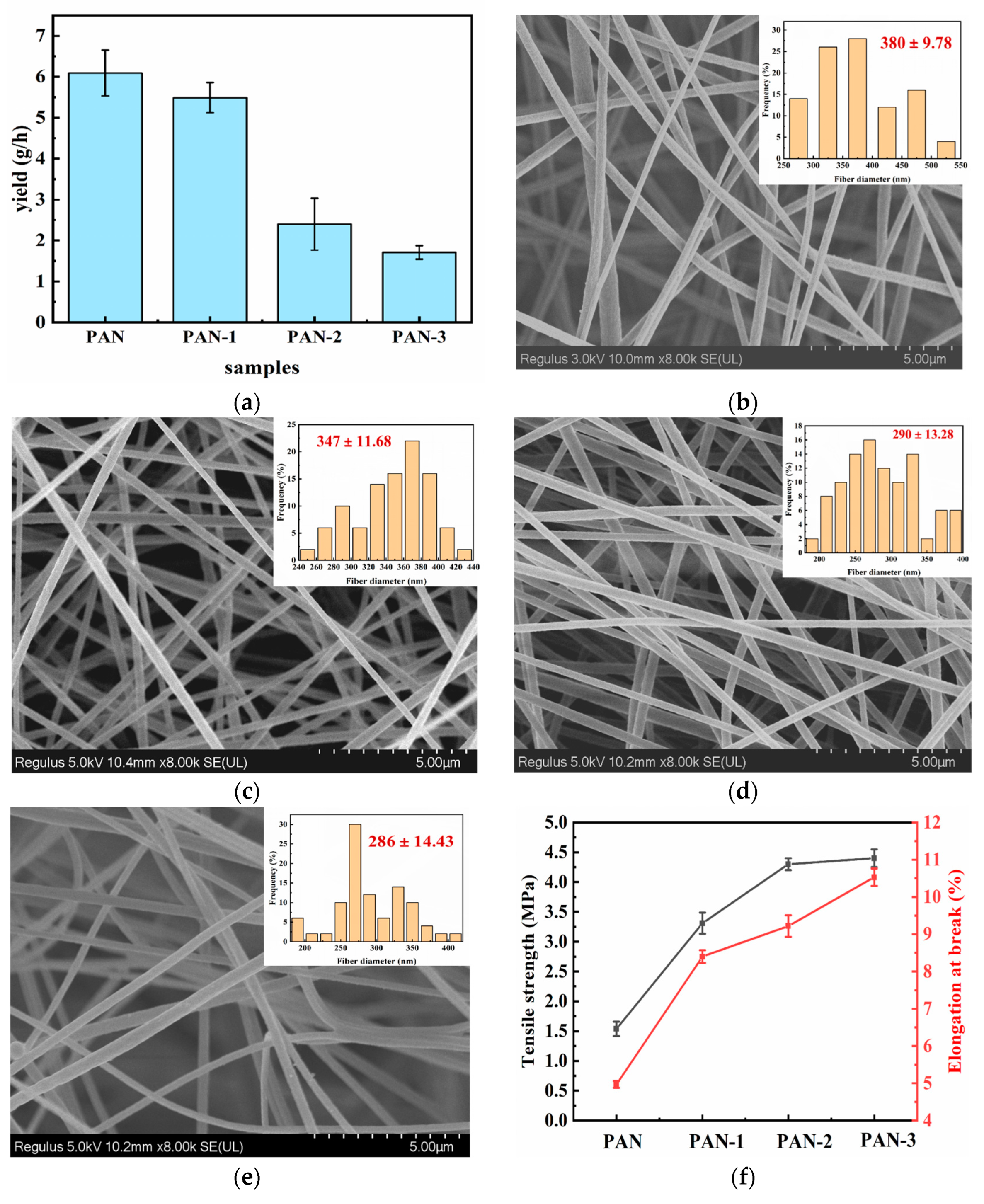
3.1. Morphology and Mechanical Property of Separators

The morphologies of PAN/PU separators were carried out using SEM, and their diameter distributions and average diameters of nanofibers were determined. As illustrated in Figure 2b–e, the SEM pictures of PAN/PU separators all exhibited a three-dimensional porous network structure, which could better absorb the electrolyte. The average nanofiber diameter of PAN-1 was larger than that of PAN-3 and PAN-2 due to its higher viscosity of the spinning solution (Table 1) [43], while the average fiber diameter of PAN-2 (290 ± 13.28 nm) was similar to that of PAN-3 (286 ± 14.43 nm) because of their similar spinning solution properties. Generally, the average fiber diameter influences the strength of nanofiber separators, and the separator with a smaller fiber diameter has higher strength [45].
It can be found from Figure 2f that the tensile strength and elongation at break of the separators increased as the PU contents increased. However, when the content of PU in the separator increased to a certain value, the tensile strength of separator would no longer continue to increase. The tensile strengths of PAN/PU composite separators were 3.3 ± 0.18 MPa (PAN-1), 4.3 ± 0.1 MPa (PAN-2) and 4.4 ± 0.15 MPa (PAN-3), respectively, and their values of elongation at break were about 8.40 ± 0.17%, 9.22 ± 0.29%, and 10.53 ± 0.23%, respectively, which could offer apparently higher mechanical properties than the pure PAN separator (1.54 ± 0.12 MPa, 4.97 ± 0.09%), making them suitable for practical LIB applications.

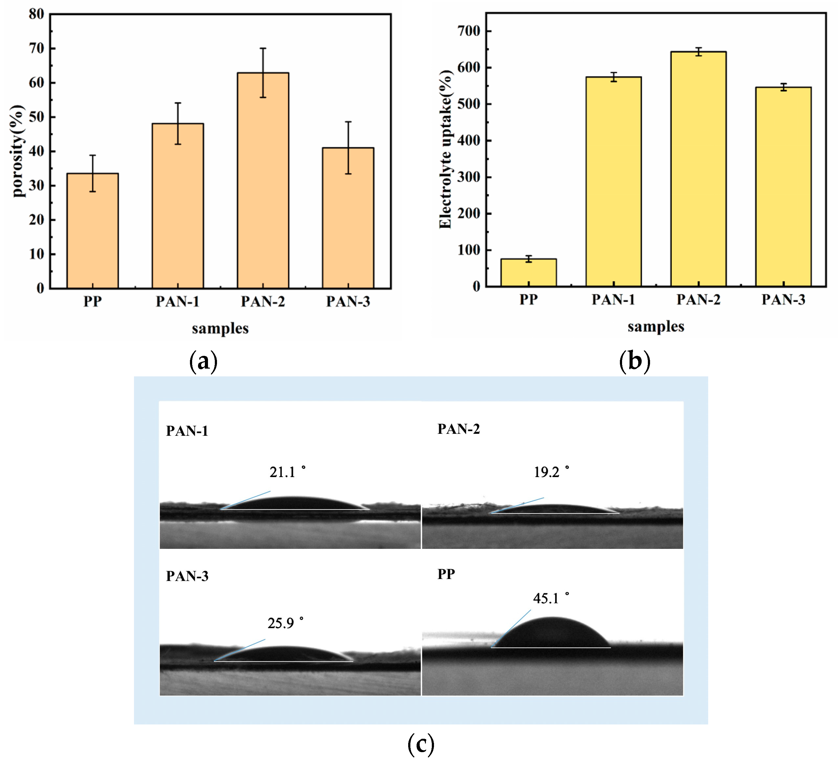
3.2. Porosity and the Electrolyte Affinity of Separators

Generally, the high porosity of the separator can make the electrolyte more easily be absorbed and enable the separator to store more lithium ions (Li+), providing convenient conditions for the transportation of Li+. Figure 3a displays the porosities of PAN/PU separators, which were much higher than PP, especially PAN-2. The high porosity of PAN-2 could make it have a large amount of pores to store the electrolyte, which was conducive to Li+ transportation between the cathode and anode, thus giving the battery assembled from it the best electrochemical performance [46].
The excellent electrolyte affinity of the separator can enhance its ionic conductivity and reduce the internal resistance of LIBs, which is crucial for the cycling and rate performances of LIBs [47]. The electrolyte affinity evaluation of separators is generally based on two aspects: electrolyte uptake rate and electrolyte wettability. The higher the electrolyte uptake rate of the separator, the better its electrolyte wettability, indicating its better electrolyte affinity. The electrolyte uptake rate of separators (Figure 3b) exhibited that the PAN/PU separators had higher electrolyte uptake rates than PP, which were consistent with the porosity of various separators, demonstrating that a nanofiber separator with a three-dimensional network structure was conducive to the absorption of electrolyte, and the PAN/PU separators were more conducive to transport Li+ rapidly. Among them, PAN-2 exhibited the highest electrolyte uptake rate due to it having the highest porosity.
In comparison to PP, the PAN/PU separators quickly absorbed the electrolyte because of their higher electrolyte uptake rates, where the electrolyte droplets easily spread over a wide area of PAN/PU separators, especially PAN-2, indicating good electrolyte wettability of nanofiber separators. To quantitatively evaluate the wettability of separators, the images of electrolyte droplets were photographed using an optical contact measuring device of a contact angle analyzer system, and their contact angles were used to evaluate the electrolyte wettability of separators. The smaller the contact angle of the separator, the better its electrolyte wettability. As illustrated in Figure 3c, the smaller electrolyte contact angles of PAN/PU separators originated from the superiority of nanofiber separators [48]. Moreover, the contact angle of PAN-2 (19.2°) was the smallest due to it having the highest porosity. The high porosity of PAN-2 would provide it with the most pores to store the electrolyte and absorb them the fastest, leading to it having the highest electrolyte uptake rate and smallest contact angle.

3.3. Thermal Stability

The outstanding thermal stability of separators is as vital as their excellent mechanical properties to improve the safety of LIBs. To compare the thermal stability of PP and PAN/PU separators, they were held at 140 °C, 160 °C and 180 °C within a heat oven for half an hour respectively to observe their dimensional changes. The thermal shrinkage values of all separators at the above four temperatures are summarized in Table 2. PP exhibited a significant heat shrinkage (97.89 ± 0.42) under 140 °C, which might cause a short circuit inside the battery and severe security problems. However, the PAN/PU separators almost maintained their original dimensions under 180 °C and the thermal shrinkage rate of PAN-2 (4.21 ± 3.93%) was much lower than that of PP, indicating that PAN-2 with excellent thermal stability and mechanical properties was supposed to be applied in safe LIB applications.

3.4. Electrochemical Performances of Nanofiber Separators

As is known, the ionic conductivity, interfacial impedance and lithium-ion transference number ( t L i + ) are significant in characterizing the electrochemical performance of an LIB separator. Ionic conductivity determines the degree of ion transfer through the separator, and higher ionic conductivity means that ions are more likely to migrate, affecting the internal resistance performance of LIBs [47]. Nyquist plots of stainless steel (SS) symmetrical batteries showed that the intersection point on the real axis represented the bulk resistance of the separator (Rb). It is illustrated in Figure 4a,b that the Rb of separators were 4.0 Ω (PP), 3.2 Ω (PAN-1), 1.7 Ω (PAN-2), 2.1 Ω (PAN-3), respectively, and their ionic conductivities ( δ ) were calculated by Eq. 5 to be 0.24, 1.56, 1.90 and 0.98 mS/cm, respectively. This was because, compared to PP, the PAN/PU separators had a higher porosity and higher electrolyte affinity, which were beneficial for reducing the transference resistance of Li+ [49]. PAN-2 had the smallest Rb and highest ionic conductivity due to its high porosity and electrolyte affinity.
A good interfacial compatibility is key to maintaining the properties of LIBs, helping to weaken the ohmic polarization in the charge–discharge reaction. The interfacial resistance (Rint) of batteries (Figure 4c) using lithium metal (LM) as the electrode was measured, and that of the battery with PAN-2 was the smallest (176.5 Ω) compared with those of other separators. Therefore, the PAN-2 nanofiber separator had the best interface compatibility, because a smaller Rint meant better interface compatibility. This was attributed to its excellent electrolyte affinity, which facilitated good contact between the separator and electrodes and reduced the interfacial resistance [50].
Ionic conductivity is used to characterize the ability of the separator to allow Li+ to pass, while  t L i +  is used to characterize the transference of Li+ in the electrolyte, which is measured via a conjunction of chronoamperometry (the potentiostatic polarization method) and EIS method using a LM/separator/LM battery. Generally,  t L i +  is not only affected by the pore structure and electrolyte affinity of separators, but also by the interaction between the separator surface and the electrolyte. As exhibited in Figure 4d–h and Table 3 t L i + values of PAN-1, PAN-2, PAN-3 and PP were calculated using Equation (6). The battery with PAN-2 had an outstanding lithium-ion conductivity and  t L i + (0.265) because of its high porosity and excellent interaction with the electrolyte, thus increasing the transference of Li+ [51].
The LSV curves reflect the electrochemical stability window of the electrolyte system, and a higher electrochemical stability window is conducive to meeting the long-term stable operation of LIBs. Focusing on Figure 4i, the electrochemical window of batteries with different separators were about 4.3 V (PP), 4.7 V (PAN-1), 4.9 V (PAN-2), and 4.8 V (PAN-3), respectively, indicating that PAN-2 was more stable for the application of high-voltage LIBs.

3.5. Cycling and Rate Performances of Batteries

The cycling and rate performances of batteries are very critical to evaluate the practical applications of an LIB separator. The cycling performance of LiFePO4/separator/LM batteries using different separators was measured at the same C-rate of 0.5 C, as indicated in Figure 5a. All the batteries were activated at a low C-rate of 0.1 C in the first five cycles. The battery with PAN-2 exhibited the highest discharge capacity of 148 mAh/g at 0.5 C, and it could still maintain 139 mAh/g after 100 cycles at 0.5 C, revealing the superiority of the battery with PAN-2, which could be applied to long-term testing.
Figure 5b shows the rate performance of LiFePO4/separator/LM batteries with different separators. The specific capacities of batteries with PP, PAN-1, PAN-2 and PAN-3 at 0.1 C were 151, 156, 156 and 146 mAh/g, respectively, and when the C-rate reached 2 C, their specific capacities still maintained 103, 102, 114 and 108 mAh/g, respectively. Notably, the discharge capacity of the battery with PP at 0.2 C after cycling at 2 C was far from its initial specific capacity at 0.2 C. However, the specific capacity of the battery with PAN-2 could recover to 144 mAh/g, which was the highest value among the batteries assembled with PAN/PU nanofiber separators, illustrating that the battery with PAN-2 had brilliant reversibility. Due to the good electrolyte affinity of PAN-2, the battery with PAN-2 exhibited a lower internal resistance and loss, leading to an enhanced discharge capacity.

4. Conclusions

In summary, PAN/PU composite nanofiber separators for LIBs were successfully prepared using SSFSE in batch. Compared with the traditional SNE, the efficiency of SSFSE was greatly improved, and the highest yield of PAN/PU separators could achieve 5.49 g/h. The results illustrated that the appropriate addition of PU could efficiently enhance the mechanical property and thermal stability of separators as well as reduce the risk of short circuiting batteries, thus enhancing the security performance of LIBs. When the weight ratio of PAN:PU was 8:2, the porosity and electrolyte uptake of separators were the highest, which were 62.9% and 643.3%, respectively. Therefore, the battery assembled with PAN-2 showed excellent electrochemical properties, cycling performance and rate capability and had a capacity retention rate of 93.9% after 100 cycles at 0.5 C. This will be of great significance for improving the comprehensive performances of LIBs.

Author Contributions

Conceptualization, W.D. and L.X.; data curation, W.D.; investigation, W.D.; project administration, L.X.; supervision, L.X.; validation, L.X.; writing—original draft, W.D.; writing—review and editing, L.X. All authors have read and agreed to the published version of the manuscript.

Funding

This research was funded by the National Natural Science Foundation of China, grant number 11672198, Jiangsu Higher Education Institutions of China, grant number 20KJA130001, Jiangsu Engineering Research Center of Textile Dyeing and Printing for Energy Conservation, grant number ERC-Q811580722, and PAPD (A Project Funded by the Priority Academic Program Development of Jiangsu Higher Education Institutions).

Data Availability Statement

The data presented in this study are available on request from the corresponding author.

Conflicts of Interest

The authors declare that they have no known competing financial interests or personal relationships that could have appeared to influence the work reported in this paper.

References

  1. Tomaszewska, A.; Chu, Z.Y.; Feng, X.N.; O’Kane, S.; Liu, X.H.; Chen, J.Y.; Ji, C.Z.; Endler, E.; Li, R.H.; Liu, L.S.; et al. Lithium-ion battery fast charging: A review. Etransportation 2019, 1, 100011. [Google Scholar] [CrossRef]
  2. Liu, K.X.; Wang, Z.Y.; Shi, L.Y.; Jungsuttiwong, S.; Yuan, S. Ionic liquids for high performance lithium metal batteries. J. Energy Chem. 2021, 59, 320–333. [Google Scholar] [CrossRef]
  3. Xia, L.; Miao, H.; Zhang, C.F.; Chen, G.Z.; Yuan, J.L. Review-recent advances in non-aqueous liquid electrolytes containing fluorinated compounds for high energy density lithium-ion batteries. Energy Storage Mater. 2021, 38, 542–570. [Google Scholar] [CrossRef]
  4. Xu, K. Nonaqueous liquid electrolytes for lithium-based rechargeable batteries. Chem. Rev. 2004, 104, 4303–4417. [Google Scholar] [CrossRef] [PubMed]
  5. Arora, P.; Zhang, Z.M. Battery separators. Chem. Rev. 2004, 104, 4419–4462. [Google Scholar] [CrossRef] [PubMed]
  6. Kim, Y.J.; Lee, S.M.; Kim, S.H.; Kim, H.S. Electrochemical and safety performances of polyimide nano fiber-based nonwoven separators for Li-ion batteries. J. Electrochem. Sci. Technol. 2015, 6, 26–33. [Google Scholar] [CrossRef]
  7. Wang, C.; Zhu, G.B.; Hu, Y.Q.; Xu, J.; Wang, L.X.; Wang, H.; Cheng, C.Z. Porous sodium alginate/boehmite coating layer constructed on PP nonwoven substrate as a battery separator through polydopamine-induced water-based coating method. Chemelectrochem 2022, 9, e202200818. [Google Scholar] [CrossRef]
  8. Yang, L.; Sheng, L.; Gao, X.X.; Xie, X.; Bai, Y.Z.; Liu, G.J.; Dong, H.Y.; Wang, T.; Huang, X.L.; He, J.P. rGO/Li-Al-LDH composite nanosheets modified commercial polypropylene (PP) separator to suppress lithium dendrites for lithium metal battery. Electrochim. Acta 2022, 430, 141073. [Google Scholar] [CrossRef]
  9. Xie, Y.J.; Pan, Y.F.; Cai, P.X. Novel PVA-based porous separators prepared via freeze-drying for enhancing performance of Lithium-ion batteries. Ind. Eng. Chem. Res. 2020, 59, 15242–15254. [Google Scholar] [CrossRef]
  10. Wang, H.F.; Li, H.B.; Yu, L.J.; Jiang, Y.M.; Wang, K.X. Synthesis of porous Al2O3-PVDF composite separators and their application in lithium-ion batteries. J. Appl. Polym. Sci. 2013, 130, 2886–2890. [Google Scholar] [CrossRef]
  11. Luo, L.; Gao, Z.H.; Zheng, Z.M.; Zhang, J.M. Polymer-in-Ceramic membrane for thermally safe separator applications. ACS Omega 2022, 7, 35727–35734. [Google Scholar] [CrossRef] [PubMed]
  12. Song, Y.Z.; Wang, L.; Cui, H.; Liang, H.M.; Hu, Q.; Ren, D.S.; Yang, Y.; Zhang, H.; Xu, H.; He, X.M. Boosting battery safety by mitigating thermal-induced crosstalk with a bi-continuous separator. Adv. Energy Mater. 2022, 12, 2201964. [Google Scholar] [CrossRef]
  13. Li, Y.F.; Li, Q.H.; Tan, Z.C. A review of electrospun nanofiber-based separators for rechargeable lithium-ion batteries. J. Power Sources 2019, 443, 227262. [Google Scholar] [CrossRef]
  14. Liu, M.; Deng, N.P.; Ju, J.G.; Fan, L.L.; Wang, L.Y.; Li, Z.J.; Zhao, H.J.; Yang, G.; Kang, W.M.; Yan, J.; et al. A review: Electrospun nanofiber materials for Lithium-sulfur batteries. Adv. Funct. Mater. 2019, 29, 1905467. [Google Scholar] [CrossRef]
  15. Zainab, G.; Wang, X.F.; Yu, J.Y.; Zhai, Y.Y.; Babar, A.A.; Xiao, K.; Ding, B. Electrospun polyacrylonitrile/polyurethane compo-site nanofibrous separator with electrochemical performance for high power lithium ion batteries. Mater. Chem. Phys. 2016, 182, 308–314. [Google Scholar] [CrossRef]
  16. Mei, S.Q.; Liu, T.; Chen, L.; Wang, Y.F. Preparation and performance of a PU/PAN lithium-ion battery separator based on a centrifugal spinning method. Appl. Sci. 2023, 13, 6682. [Google Scholar] [CrossRef]
  17. Zhou, F.L.; Gong, R.H.; Porat, I. Needle and needleless electrospinning for nanofibers. J. Appl. Polym. Sci. 2010, 115, 2591–2598. [Google Scholar] [CrossRef]
  18. He, J.H.; Liu, Y.; Xu, L.; Yu, J.Y.; Sun, G. BioMimic fabrication of electrospun nanofibers with high-throughput. Chaos Soliton. Fract. 2008, 37, 643–651. [Google Scholar] [CrossRef]
  19. Jiang, G.J.; Johnson, L.; Xie, S. Investigations into the mechanisms of electrohydrodynamic instability in free surface electrospinning. Open Phys. 2019, 17, 313–319. [Google Scholar] [CrossRef]
  20. Yusuf, A.; Avvaru, V.S.; Dirican, M.; Sun, C.C.; Wang, D.Y. Low heat yielding electrospun phosphenanthrene oxide loaded polyacrylonitrile composite separators for safer high energy density Lithium-ion batteries. Appl. Mater. Today. 2020, 20, 100675. [Google Scholar] [CrossRef]
  21. Dong, G.X.; Li, H.J.; Wang, Y.; Jiang, W.J.; Ma, Z.S. Electrospun PAN/cellulose composite separator for high performance lith-ium-ion battery. Ionics 2021, 27, 2955–2965. [Google Scholar] [CrossRef]
  22. Mohanta, J.; Kwon, O.H.; Choi, J.H.; Yun, Y.M.; Kim, J.K.; Jeong, S.M. Preparation of highly porous PAN-LATP membranes as separators for lithium ion batteries. Nanomaterials 2019, 9, 1581. [Google Scholar] [CrossRef] [PubMed]
  23. Byun, S.; Lee, S.; Song, D.; Ryou, M.H.; Lee, Y.M.; Park, W.H. A crosslinked nonwoven separator based on an organosoluble polyimide for high-performance lithium-ion batteries. J. Ind. Eng. Chem. 2019, 72, 390–399. [Google Scholar] [CrossRef]
  24. Li, M.L.; Sheng, L.; Xu, R.; Yang, Y.; Bai, Y.Z.; Song, S.J.; Liu, G.J.; Wang, T.; Huang, X.L.; He, J.P. Enhanced the mechanical strength of polyimide (PI) nanofiber separator via PAALi binder for lithium ion battery. Compos. Commun. 2021, 24, 100607. [Google Scholar] [CrossRef]
  25. Wang, L.L.; Liu, F.; Shao, W.L.; Cui, S.Z.; Zhao, Y.M.; Zhou, Y.M.; He, J.X. Graphite oxide dopping polyimide nanofiber mem-brane via electrospinning for high performance lithium-ion batteries. Compos. Commun. 2019, 16, 150–157. [Google Scholar] [CrossRef]
  26. Wu, H.Y. Electrospun graphene oxide (GO)/polyvinylidene flfluoride (PVDF) nanofiber separator for lithium-ion battery. J. Optoelectron. Adv. Mater. 2022, 24, 82–87. [Google Scholar]
  27. Chen, Y.; Qiu, L.L.; Ma, X.Y.; Dong, L.K.; Jin, Z.F.; Xia, G.B.; Du, P.F.; Xiong, J. Electrospun cellulose polymer nanofiber mem-brane with flame resistance properties for lithium-ion batteries. Carbohyd. Polym. 2020, 234, 115907. [Google Scholar] [CrossRef]
  28. Li, D.T.; Gao, X.X.; Cao, M.; Sheng, L.; Yang, L.; Xie, X.; Gong, Y.; Hu, Q.Y.; Xie, Q.Q.; Wang, T.; et al. High-performance nano-TiO2@polyvinylidene fluoride composite separators prepared by electrospinning for safe lithi-um-ion battery. J. Appl. Polym. Sci. 2023, 140, e53618. [Google Scholar] [CrossRef]
  29. Chen, Y.; Qiu, L.L.; Ma, X.Y.; Chu, Z.D.; Zhuang, Z.S.; Dong, L.K.; Du, P.F.; Xiong, J. Electrospun PMIA and PVDF-HFP compo-site nanofibrous membranes with two different structures for improved lithium-ion battery separators. Solid State Ionics 2020, 347, 115253. [Google Scholar] [CrossRef]
  30. Jiang, W.W.; Han, Y.; Ding, Y.H. Sepiolite and ZIF-67 co-modified PAN/PVdF-HFP nanofiber separators for advanced Li-ion batteries. Nanotechnology 2022, 33, 425601. [Google Scholar] [CrossRef]
  31. Chen, D.X.; Wang, X.; Liang, J.Y.; Zhang, Z.; Chen, W.P. A Novel electrospinning polyacrylonitrile separator with dip-coating of zeolite and phenoxy resin for li-ion batteries. Membranes 2021, 11, 267. [Google Scholar] [CrossRef] [PubMed]
  32. Gong, W.Z.; Zhang, Z.; Wei, S.Y.; Ruan, S.L.; Shen, C.Y.; Turng, L.S. Thermosensitive polyacrylonitrile/polyethylene oxide/polyacrylonitrile membrane separators for prompt and safer thermal lithium-ion battery shutdown. J. Electrochem. Soc. 2020, 167, 020509. [Google Scholar] [CrossRef]
  33. Yu, Y.G.; Zhang, F.L.; Liu, Y.; Zheng, Y.S.; Xin, B.J.; Jiang, Z.L.; Peng, X.X.; Jin, S.X. Waterproof and breathable polyacrylonitrile/(polyurethane/fluorinated-silica) composite nanofiber membrane via side-by-side electrospinning. J. Mater. Res. 2020, 35, 1173–1181. [Google Scholar] [CrossRef]
  34. Lee, J.; Yoon, J.; Jeon, J.; Hong, Y.; Oh, S.G.; Huh, H. Electrospun PVDF-HFP/PAN bicomponent nanofibers as separators in lithium-ion batteries with high thermal stability and electrolyte wettability. Korean J. Chem. Eng. 2023, 40, 1901–1911. [Google Scholar] [CrossRef]
  35. Liu, T.; Hu, X.M.; Zhang, Y.D.; He, T.; Zhou, J.P.; Qiao, J.Q. Ion transport regulated lithium metal batteries achieved by electrospun ZIF/PAN composite separator with suitable electrolyte wettability. Batteries 2023, 9, 166. [Google Scholar] [CrossRef]
  36. Tang, L.P.; Wu, Y.K.; He, D.; Lei, Z.Q.; Liu, N.Q.; He, Y.; De Guzman, M.R.; Chen, J. Electrospun PAN membranes toughened and strengthened by TPU/SHNT for high-performance lithium-ion batteries. J. Electroanal. Chem. 2023, 931, 117181. [Google Scholar] [CrossRef]
  37. Chen, Y.F.; Gao, Y.; Jian, J.J.; Lu, Y.H.; Zhang, B.Y.; Liu, H.Q.; Li, L.; Wang, X.W.; Kuang, C.X.; Zhai, Y.Y. A dual-layer mi-cro/nanostructured fibrous membrane with enhanced ionic conductivity for lithium-ion battery. Electrochim. Acta 2018, 292, 357–363. [Google Scholar] [CrossRef]
  38. Shao, Z.B.; Yu, L.; Xu, L.; Wang, M.D. High-throughput fabrication of quality nanofibers using a modified free surface elec-trospinning. Nanoscale Res. Lett. 2017, 12, 470. [Google Scholar] [CrossRef]
  39. Shao, Z.B.; Song, Y.H.; Xu, L. Fomation mechanism of highly aligned nanofibers by a modified bubble electrospinning. Therm. Sci. 2018, 22, 5–10. [Google Scholar] [CrossRef]
  40. Cheng, T.T.; Xu, L.; Wang, M.D. Effect of surface active agent on bubble-electrospun polyacrylonitrile nanofibers. Therm. Sci. 2019, 23, 2481–2487. [Google Scholar] [CrossRef]
  41. Wu, D.Z.; Xiao, Z.M.; Deng, L.; Sun, Y.; Tan, Q.L.; Dong, L.X.; Huang, S.H.; Zhu, R.; Liu, Y.F.; Zheng, W.X.; et al. Enhanced Deposition Uniformity via an Auxiliary Electrode in Massive Electrospinning. Nanomaterials 2016, 6, 135. [Google Scholar] [CrossRef] [PubMed]
  42. Liu, Q.H.; Jiang, W.; Lu, W.Z.; Mei, Y.F.; He, F.K.; Zhang, M.H.; Liu, Y.; Chen, Y.Q.; Peng, J.F.; Ding, Y.H. Anisotropic semi-aligned PAN@PVdF-HFP separator for Li-ion batteries. Nanotechnology 2020, 31, 435701. [Google Scholar] [CrossRef] [PubMed]
  43. Song, Y.H.; Sun, Z.Y.; Xu, L.; Shao, Z.B. Preparation and Characterization of Highly Aligned Carbon Nano-tubes/Polyacrylonitrile Composite Nanofibers. Polymers 2017, 9, 1. [Google Scholar] [CrossRef] [PubMed]
  44. Choi, S.; Park, S.; Huh, H. PU-RGO Composite; Effect of Chain Extender’s Structure on Properties. J. Nanosci. Nanotechnol. 2017, 17, 7480–7484. [Google Scholar] [CrossRef]
  45. Bai, Z.K.; Xu, W.L.; Xu, J.; Liu, X.; Yang, H.J.; Xiao, S.L.; Liang, G.J.; Chen, L.B. Microstructure and mechanical properties of polyurethane fibrous membrane. Fiber. Polym. 2012, 13, 1239–1248. [Google Scholar] [CrossRef]
  46. Xiao, W.; Cheng, D.; Huang, L.; Song, J.; Yang, Z.X.; Qiao, Q.D. An integrated separator/anode assembly based on electrospin-ning technique for advanced lithium-ion batteries. Electrochim. Acta 2021, 389, 138776. [Google Scholar] [CrossRef]
  47. Jiang, F.J.; Nie, Y.; Yin, L.; Feng, Y.; Yu, Q.C.; Zhong, C.Y. Core-shell-structured nanofibrous membrane as advanced separator for lithium-ion batteries. J. Membr. Sci. 2016, 510, 1–9. [Google Scholar] [CrossRef]
  48. He, T.S.; Fu, Y.R.; Meng, X.L.; Yu, X.D.; Wang, X.L. A novel strategy for the high performance supercapacitor based on polyac-rylonitrile-derived porous nanofibers as electrode and separator in ionic liquid electrolyte. Electrochim. Acta 2018, 282, 97–104. [Google Scholar] [CrossRef]
  49. Li, Y.; Cao, J.; Liu, Q.; Wang, A.X.; Li, B.H. A sandwich-structure composite membrane as separator with high wettability and thermal properties for advanced lithium-ion batteries. Int. J. Electrochem. Sci. 2019, 14, 7088–7103. [Google Scholar] [CrossRef]
  50. Xie, Y.; Xiang, H.F.; Shi, P.C.; Guo, J.P.; Wang, H.H. Enhanced separator wettability by LiTFSI and its application for lithium metal batteries. J. Membr. Sci. 2017, 524, 315–320. [Google Scholar] [CrossRef]
  51. Liu, H.Y.; Liu, L.L.; Yang, C.L.; Li, Z.H.; Xiao, Q.Z.; Lei, G.T.; Ding, Y.H. A hard-template process to prepare three-dimensionally macroporous polymer electrolyte for lithium-ion batteries. Electrochim. Acta 2014, 121, 328–336. [Google Scholar] [CrossRef]
Figure 1. Batch preparation of PAN/PU composite nanofiber separators.
Batteries 10 00006 g001
Figure 2. (a) Yields of PAN, PAN-1, PAN-2 and PAN-3 via SSFSE; SEM pictures and their corresponding fiber distribution of (b) pure PAN, (c) PAN-1, (d) PAN-2 and (e) PAN-3; (f) mechanical properties of PAN-based separators.
Batteries 10 00006 g002
Figure 3. (a) Porosity, (b) electrolyte uptake rates and (c) electrolyte contact angles of separators.
Batteries 10 00006 g003
Figure 4. (a,b) Impedance diagrams of stainless steel symmetrical batteries (SS/separator/SS) at low and high measurements, respectively; (c) nyquist plots of the symmetric batteries (LM/separator/LM); (d) chronoamperometry profiles of LM/separator/LM batteries; impedance spectra before and after polarization of LM/separator/LM batteries for (e) PP, (f) PAN-1, (g) PAN-2, and (h) PAN-3; and (i) LSV curves of the PP and PAN/PU at scan rate of 10 mV s−1.
Batteries 10 00006 g004
Figure 5. (a) Cycling performance at 0.5 C and (b) rate performance of LiFePO4/separator/LM batteries with different separators.
Batteries 10 00006 g005
Table 1. Viscosity and conductivity of spinning solutions.
Spinning Solutions of SamplesSpinning Solution Property
Viscosity (mPa·s)Conductivity (μS·cm−1)
PAN1789 ± 5856 ± 2
PAN-11179 ± 2735 ± 12
PAN-2844 ± 7678 ± 8
PAN-3730 ± 3622 ± 2
Table 2. Thermal shrinkage rates of separators after thermal treatment at different temperatures.
S(%)T(°C)25140160180
Separator
PP097.89 ± 0.42100100
PAN-1001.05 ± 2.893.16 ± 1.45
PAN-2002.63 ± 1.584.21 ± 3.93
PAN-305.26 ± 3.167.89 ± 4.5310.52 ± 5.50
Table 3. Rb δ  and tLi+ of batteries for different separators.
SampleThickness (mm)Rb (Ω)   δ tLi+
PP0.025 ± 0.0024.00.240.136
PAN-10.084 ± 0.0082.11.560.215
PAN-20.083 ± 0.0071.71.900.265
PAN-30.080 ± 0.0053.20.980.058
Disclaimer/Publisher’s Note: The statements, opinions and data contained in all publications are solely those of the individual author(s) and contributor(s) and not of MDPI and/or the editor(s). MDPI and/or the editor(s) disclaim responsibility for any injury to people or property resulting from any ideas, methods, instructions or products referred to in the content.

