Article

Thermal Modeling of Lithium-Ion Battery Under High-Frequency Current Excitation and Comparative Study of Self-Heating Scheme

by
Hao Li
1,2,
Jianan Chen
1,2,
Yingtao Ma
1,2,
Weizhi Liu
1,2,
Lei Tang
1,2 and
Bing Liu
1,2,*
1
Locomotive & Car Research Institute, China Academy of Railway Sciences Corporation Limited, Beijing 100081, China
2
Beijing Zongheng Electro-Mechanical Technology Co., Ltd., Beijing 100094, China
*
Author to whom correspondence should be addressed.
Batteries 2024, 10(12), 419; https://doi.org/10.3390/batteries10120419
Submission received: 31 August 2024 / Revised: 25 October 2024 / Accepted: 29 October 2024 / Published: 29 November 2024
(This article belongs to the Section Battery Modelling, Simulation, Management and Application)

Abstract

:
High-frequency ripple current excitation reduces the lithium precipitation risk of batteries during self-heating at low temperatures. To study the heat generation behavior of batteries under high-frequency ripple current excitation, this paper establishes a thermal model of LIBs, and different types of LIBs with low-temperature self-heating schemes are studied based on the established thermal model. Under the consideration of contact impedance, this paper tests the heat production of the battery under high-frequency ripple current and establishes an accurate thermal model of a lithium-ion battery under the excitation of high-frequency ripple current, and the absolute value of the maximum relative error between the measurement results and the thermal model is reduced from 181.4% to less than 20.6%, which makes the battery thermal model under high-frequency ripple current excitation more accurate. Then, based on the established thermal model, the calculation method of the minimum heating power required for different batteries under the same low-temperature self-heating conditions is proposed for batteries of different sizes, thermal properties, and internal resistances, and the preferred low-temperature self-heating scheme for different types of batteries is proposed by comparing the current multiplicity required for different high-frequency ripple current self-heating schemes.

1. Introduction

1.1. Study on the Thermal Model of LIBs Under High-Frequency Current

LIBs are widely employed as power sources for on-board energy storage devices due to their high energy and power densities, along with their excellent cycling performance. However, their performance is significantly impaired at low temperatures, as evidenced by a steep decline in available energy and power when temperatures dip below 0 °C. Additionally, the risk of lithium plating emerges, further limiting their charging capacity in cold environments [1,2,3]. Notably, the threat of lithium precipitation is mitigated by the minimal electrochemical reactions that occur within the battery when exposed to high-frequency currents.
Consequently, research on utilizing DC–DC converters to generate high-frequency currents for battery heating at low temperatures has garnered significant attention [4,5,6,7,8]. Currently, two primary methods for low-temperature self-heating of batteries with high-frequency current through DC–DC converters are prevalent: the high-frequency current self-impedance heating method and the combined high-frequency current internal and external heating method, as illustrated in Figure 1. Both techniques employ fixed-frequency high-frequency ripple current to warm the lithium-ion battery, and the self-heating power of the battery can be adjusted by varying the current amplitude, providing a high degree of flexibility in regulating the heating power and promising applications. Unfortunately, there are many studies focusing on long-time scales (voltage data intervals greater than 1 s) for LIBs [9,10,11,12,13,14], while studies describing the high-frequency thermal characteristics of LIBs are more scarce.
However, the current research regarding the thermal model of LIBs under high-frequency currents remains incomplete. During operation under non-sinusoidal high-frequency ripple currents, researchers have attempted to model the battery’s heat production using EIS data and current data, yet the model outcomes have deviated significantly from actual measurements. This discrepancy has led researchers to hypothesize the existence of an additional heat-generation behavior that significantly impacts the modeling accuracy. Therefore, identifying the sources of errors between theoretical calculations and empirical measurements, and consequently enhancing the precision of heat-production models, poses an urgent challenge in the field of accurate thermal modeling for LIBs operating under high-frequency ripple currents.
Shang et al. (2018, 2021) have designed a low-temperature self-heating device specifically for LIBs [16,17]. Utilizing the battery’s impedance and collected current data, they conducted theoretical calculations to estimate the heat production of the batteries under high-frequency ripple currents. The device was capable of generating a high-frequency ripple current with a triangular wave ripple amplitude of 3.1 C and a frequency ranging from 833 Hz to 20 kHz. However, the simulation results exhibited deviations from the actual outcomes. To address this issue, an empirical model incorporating a correction factor was employed to describe the battery’s heat-production model under high-frequency ripple conditions. Figure 2 depicts the temperature simulation curves before and after the introduction of this correction. While the inclusion of the correction term enhances the accuracy of the final battery-temperature calculation, it compromises the precision of fitting the temperature change during the initial heating phase.
Hu et al. (2022) conducted comprehensive low-temperature self-heating experiments on 18650 batteries, utilizing a custom-designed power electronic device. They devised two distinct experimental setups to validate the self-heating effect of LIBs [18]. In their theoretical analysis of heat production, they factored in the influence of high harmonics in the current on heat generation behavior and established a corresponding heat-production model.
The experiments encompassed two sets of high-frequency ripple currents. The first set involved RMS values of 2.48 A and frequencies of 3.9 kHz and 20 kHz, while the second set featured RMS values of 2.15 A and frequencies of 1.58 kHz and 15.8 kHz. However, a notable discrepancy emerged between the theoretical predictions and the actual test results, prompting the authors to postulate the existence of “unknown additional heat sources”. These additional heat sources were attributed to the higher temperature rise observed in the batteries due to the higher frequency currents.
To quantify the divergence between the theoretical and experimental values, the authors employed their literature data on the battery’s EIS at −20 °C and the heat-production power at the higher harmonics of a current with an RMS value of 2.78 A at 1.58 kHz and 15 kHz (0.0557 W and 0.1389 W, respectively). They converted this difference into impedance values, and the results of their calculations are presented in Table 1. The full names of the items in the table, from the first to the last column, are ‘Frequency’, ‘Impedance at corresponding frequency’, ‘RMS value of current’, ‘Heating power of the higher harmonics’, ‘Theoretical calculation of heating power’, ‘Measured value of thermal power production’, ‘Gap between theoretical and reality’, and ‘Real impedance value calculated by difference’.
In this instance, the heating power generated by high harmonics at varying RMS and frequency currents is determined using Equations (1) and (2). Figure 3a,b illustrate the EIS graphs obtained in a warm environment, which depict the results of the battery’s heating-power test at high-frequency currents of 1.58 kHz and 15 kHz, respectively.
By analyzing the discrepancy between the theoretically calculated and experimentally measured heating-power values and converting this difference into actual impedance, it becomes evident that when the battery is heated at a constant frequency but with varying RMS values, the impedance values derived from the additional heating power are remarkably similar. Furthermore, these converted impedance values are extremely close to the battery’s intrinsic impedance, making them too significant to overlook. Consequently, it is imperative to identify the source of this impedance, refine the established high-frequency heat-production model for LIBs, and verify its accuracy while mitigating any potential interference.
By evaluating the discrepancy between the theoretically calculated and experimentally measured heating-power values, and subsequently converting this difference into actual impedance, it becomes apparent that under identical frequency conditions but with varying RMS values, the impedance values derived from the additional heating exhibit remarkable similarity. Notably, these converted impedance values are exceedingly close to the battery’s inherent impedance, rendering them non-negligible. Consequently, it is imperative to identify the underlying cause of this impedance, refine the established high-frequency heat-production model for LIBs, and validate its accuracy while mitigating any potential interferences.
P 1.58 k H z I 1 = 0.0557 I 1 2 2.78 2
P 15 k H z I 2 = 0.1389 I 2 2 2.78 2
where, P 1.58 k H z I 1 is the heating power of the first group of experiments, the unit is W; P 15 k H z I 2 is the heating power of the first group of experiments, the unit is W; I 1 is the RMS value of the first set of experimental currents, the unit is A; I 2 is the RMS value of the second set of experimental currents, the unit is A.

1.2. Study on Low-Temperature Self-Heating Schemes of Different Types of Batteries

As the application scale of LIBs continues to expand, it becomes evident that batteries from different manufacturers vary significantly in terms of size, thermophysical properties, materials, and other parameters. Specifically, batteries with larger sizes and lower internal resistance tend to exhibit lower heat-production power and higher heat-dissipation power under identical high-frequency current conditions, ultimately leading to a less effective low-temperature self-impedance heating performance.
The variability in thermal physical parameters and internal resistance of batteries necessitates a tailored approach to applying different self-heating programs. Consequently, it is crucial to conduct research on the specific conditions required for different types of batteries to achieve the same low-temperature self-heating effect. This research can provide a theoretical foundation for selecting the most suitable low-temperature self-heating program for each battery type. Li et al. (2019) proposed a self-heating method for 18650 LIBs, using sinusoidal currents with frequencies of 1 C and 2 C and 1 kHz to 2 kHz for self-heating experiments on the batteries. The specific heating strategy was to find the minimum impedance of the battery in the full frequency range within the limit of the maximum voltage amplitude, thus using a larger current amplitude for self-heating, and ultimately achieving a faster heating rate [19,20]. Ji and Wang (2013) compare three self-heating strategies using a 18650 battery itself as the energy source, i.e., self-impedance heating, convective heating, and reciprocal pulse heating, as well as the use of an external power supply of a heating method [7]. Their respective merits and drawbacks were deliberated in the context of capacity loss, heating time, system longevity, and cost. The study’s findings indicate that convection heating offers the fastest heating rate, whereas employing positive and negative pulsed high-frequency currents results in minimal energy consumption for the battery. In the case of external power heating, high-frequency AC signals with considerable amplitude are favored as they offer both high heating capacity and improved battery cycle life, with current multipliers ranging from 2 C to 3 C. It is worth noting that LIBs are not always situated in an active external environment when initiated at low temperatures. Additionally, convection heating tends to increase the temperature gradient of LIBs at lower temperatures, potentially elevating the risk of inconsistent aging among batteries. This inconsistency can lead to a decrease in the overall usable capacity of the battery pack [21,22,23,24]. Therefore, self-impedance heating utilizing high-frequency currents emerges as the least detrimental heating method for batteries.
However, when utilizing high-frequency ripple current for battery heating, the amplitude of the necessary heating current must be escalated, as the battery’s real impedance at higher frequencies is lower compared to lower frequencies. Ruan et al. (2016, 2017) conducted a study on the self-heating of 18650 batteries at low temperatures, employing sinusoidal currents at frequencies of 50 Hz, 500 Hz, and 5 kHz [25,26], as illustrated in Figure 4a. The findings reveal that for the same current amplitude, the battery’s temperature-rise rate of under 500 Hz AC is greater than that at 5 kHz. This is attributed to the higher impedance of the battery’s real part at 500 Hz, resulting in a higher temperature rise. While increasing the AC frequency aids in mitigating the risk of lithium precipitation [27], it also diminishes the heating rate. Therefore, to enhance the heating rate, it is necessary to augment the amplitude of the heating current.
It is evident that low-temperature self-heating solutions for LIBs utilizing high-frequency ripple currents have been extensively researched. However, these studies have primarily focused on 18650 small-sized batteries. As battery dimensions, thermophysical properties, and internal resistance parameters vary, the appropriate heating strategy for batteries also changes. Jiang et al. (2018) introduced a low-temperature heating strategy combining AC and DC for a pouch battery with a capacity of 35 Ah [28]. After analyzing and deriving an expression for the DC-to-AC amplitude ratio to prevent lithium-ion deposition, a rapid self-heating experiment was performed on the battery pack. Compared to 18650 batteries, the authors utilized batteries with larger sizes and lower internal resistance. Consequently, to meet the demand for low-temperature rapid self-heating, a resonant circuit was employed to generate a sinusoidal current close to 10 C, with a small amount of DC superimposed to enhance heating power, as depicted in Figure 4b. Although this achieved a better fitting effect, it also increased the equipment’s size and weight, thereby raising the engineering challenges in practical applications.
In summary, the current research on self-heating schemes for LIBs utilizing high-frequency ripple currents is well-established, and researchers have successfully achieved favorable heating outcomes tailored to their respective battery types. However, with the rapid evolution of the lithium-ion battery industry, the diversity of battery types is increasing. Due to the disparities in dimensions, thermophysical properties, and internal resistance parameters among different battery types, there are significant variations in the current multiplication required for the same low-temperature self-impedance heating approach. As LIBs serve as voltage sources, the magnitude of current directly determines the power level, which is a critical factor in determining the cost, weight, and engineering complexity of power electronic devices. Therefore, the increase in required power poses challenges to the application of low-temperature self-impedance heating technology.

1.3. The Structure of This Article

This paper tackles the significant discrepancy between the calculated and actual heat production measurements of LIBs under high-frequency ripple current conditions. To address this issue, six experiments were designed, encompassing various high-frequency current frequencies, peak-to-peak values, and distinct contact impedances. Based on these experiments, an accurate model of lithium-ion battery heat production under high-frequency ripple current excitation was developed.
For batteries exhibiting varying sizes, thermophysical properties, and internal resistances, this study proposes a method for calculating the minimum heating power required under identical low-temperature self-heating conditions. This approach is grounded in the lumped-parameter thermal equivalent circuit model, which comprehensively accounts for heat transfer and high-frequency heat production. By comparing the current multiplication rates demanded by different high-frequency ripple-current self-heating schemes, this paper recommends optimal low-temperature self-heating strategies tailored to diverse battery types.
In Section 2, a detailed description of the experimental setup for data acquisition is provided, along with the enumeration of six high-frequency circuit models that incorporate fractional orders. Section 3 outlines the battery heat-production model employed in this study. The subsequent Section 4 presents the experimental results and a comprehensive data analysis. In Section 5, a methodology for calculating the minimum power required for low-temperature self-heating under specified conditions is introduced, and a comparative analysis of various low-temperature self-heating techniques is conducted. Finally, Section 6 summarizes the key findings and conclusions of the study.

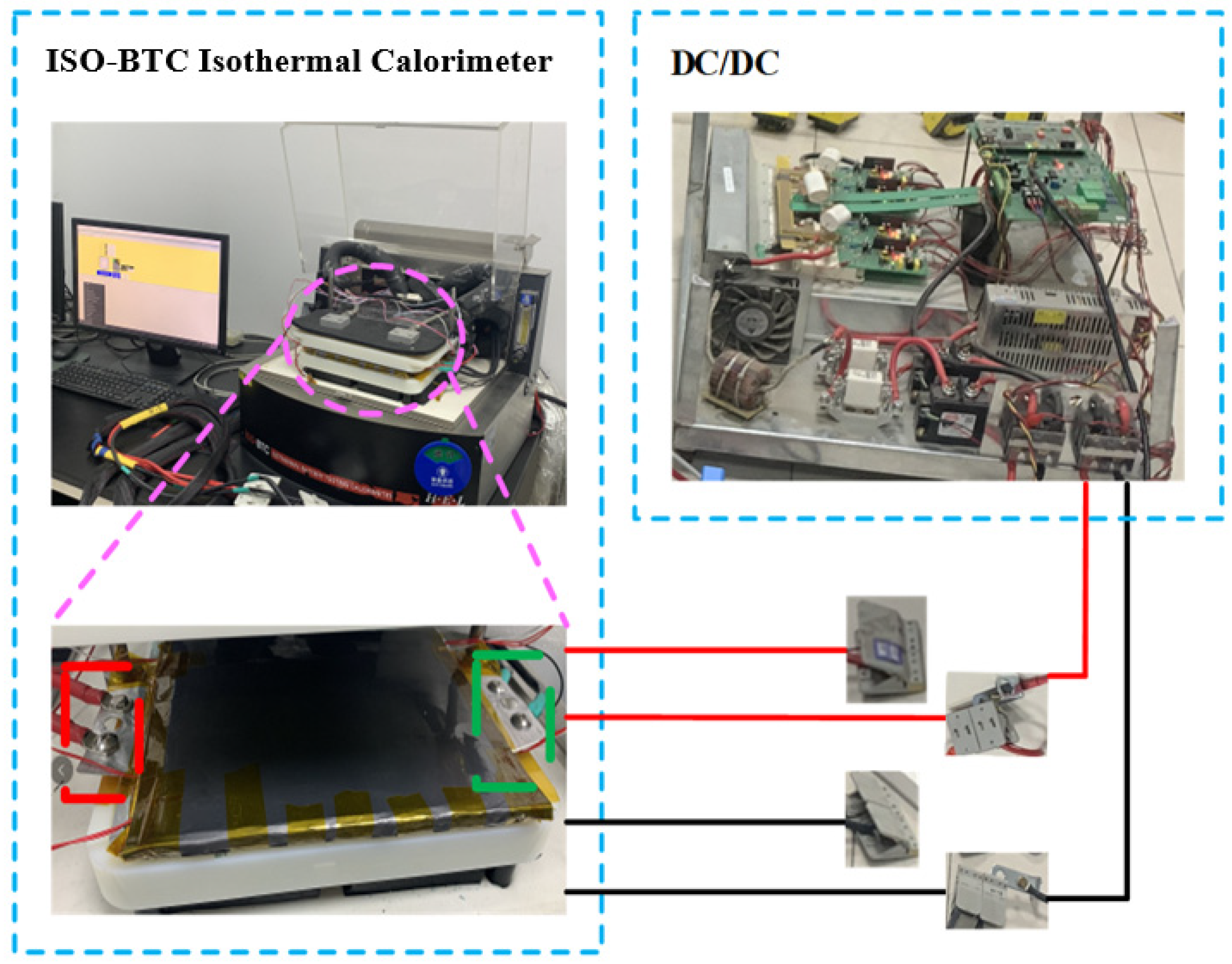
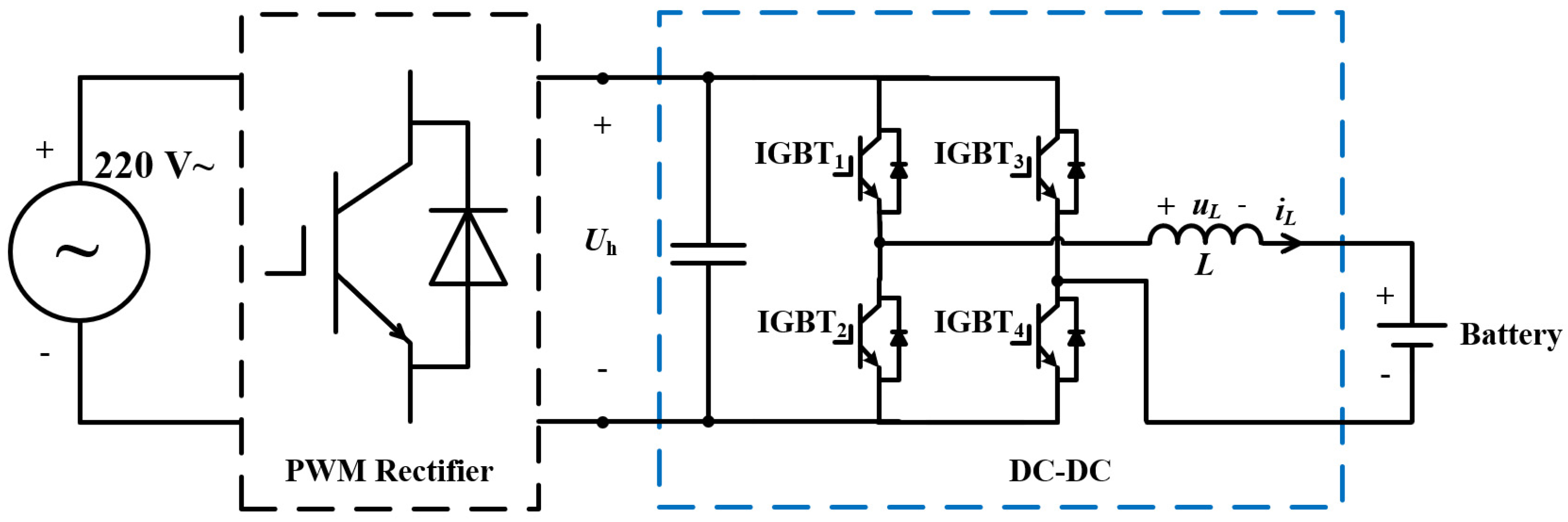
2. Experimental Setup

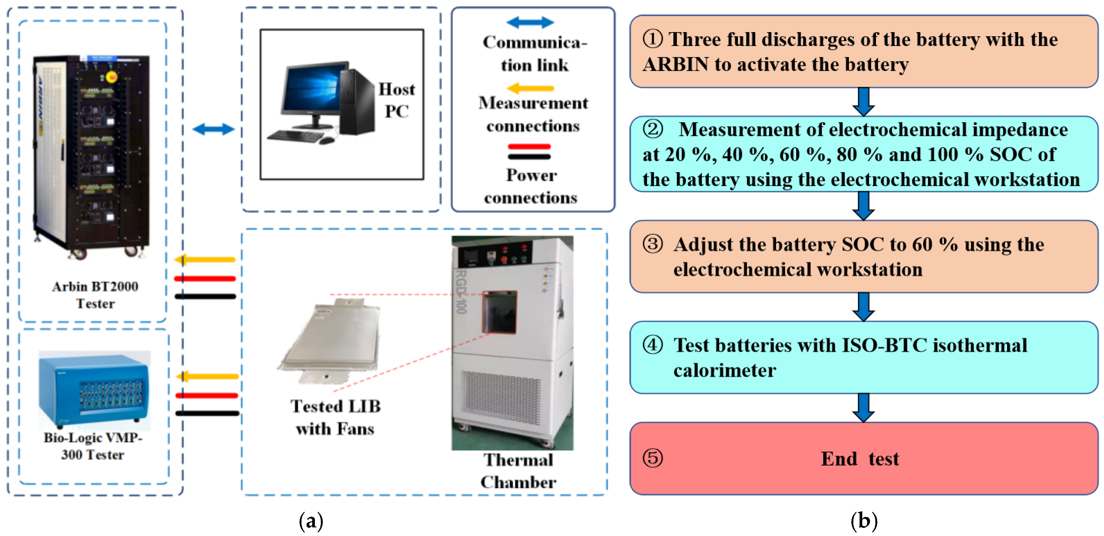
2.1. Battery Testing Systems

Figure 5a is the experimental setup used for the battery’s electrochemical impedance testing in this work, including a VMP-300 electrochemical workstation, a thermal chamber with a constant temperature of 25 °C, and a high-power-designed LTO battery. The basic parameters of the tested battery are shown in Table 2.
Figure 5b is the procedure of the experimental test. The battery under test was activated by charging and discharging three times using the Arbin before the experiment, and the electrochemical impedance of the battery was measured at 20%, 40%, 60%, 80%, and 100% using the electrochemical workstation. Afterward, the SOC of the battery was adjusted to 60% for testing in order to avoid high-frequency ripple currents that would cause the high-frequency ripple voltage of the cells to exceed the upper and lower voltage limits.
Figure 6 is the experimental setup used for battery testing in this work, including an ISO-BTC isothermal calorimeter from H.E.L. Manufacturers, Hemel Hempstead, UK, a thermal chamber with a constant temperature of 25 °C, and a high-power-designed LTO battery. The battery under test has two positions on each of the positive and negative lugs connected to the power cord, two sets of power cables are tightly connected to the battery lugs through the screws and the other end of the two bundles of power cables are connected to the output of the DC–DC. By using two sets of fixtures, the number of cable groups connecting to the battery can be adjusted to control contact with the battery’s internal resistance, allowing for adjustments to the high-frequency ripple current peak-to-peak by changing the inductance.
Figure 7 shows the topology of the DC–DC converter in Figure 6, where the high-frequency ripple amplitude of the output current can be changed by varying the value of the inductance.

2.2. Battery Test Schedule

The amplitude of the high-frequency ripple can be changed by adjusting the inductance of the DC–DC converter, and the contact impedance between the wiring harness and the battery can be changed by adjusting the wiring method. Finally, six experiments were designed as shown in Table 3. ‘SGPC’ stands for ‘Single group power cable’, and ‘DGPC’ stands for ‘Double group power cable’. The currents for Experiments 1–4 are shown in Figure 8a–d.

3. Related Work on Modeling

3.1. Heat Generation and Heat Transfer Mechanism of Lithium-Ion Batteries

According to the first law of thermodynamics, energy is conserved before and after conversion, and the change in energy of a battery in operating conditions can be described as the sum of enthalpy change and output energy as shown in Equation (3).
E = I U t + H t o t
Simultaneous derivation of both ends of Equation (3) gives Equation (4):
d E d t = P = I U + H t o t t
The enthalpy change of the battery includes the enthalpy change of reversible reaction, the enthalpy change generated by the process of phase change of materials, the enthalpy change generated by the process of heat exchange with the environment, the enthalpy change generated by the temperature change of the battery itself, the enthalpy change generated by the change of the battery’s heat capacity, and the enthalpy change generated by the mixing of substances in the battery as shown in Equation (5).
P = I U + P r e + P p e + P h t + P h a + P h c + P m e
where I is the current of the redox reaction inside the battery and the discharge direction is positive, the unit is A; U is the terminal voltage of the battery, the unit is V; P is the total power of all forms of energy output from the battery to the outside world, the unit is W; P r e is the power of heat production from the reversible reaction, the unit is W; P p e is the power of heat production from the phase change of the material in the battery, the unit is W; P h t is the power of heat exchange between the battery and the environment, the unit is W; P h a is the power of heat build-up accumulated in the battery during the process of heat production, the unit is W; P h c is the power of heat production during the process of change of the heat capacity of the battery, the unit is W; and P m e is the power of heat production of the mixing effect, the unit is W.
According to Bernardi’s assumptions, the specific heat capacity of a battery does not change significantly in most cases and can be neglected. In addition, at a constant temperature, the physical state of the reactants in the battery remains essentially unchanged, and the heat-production power of the battery-phase transition can also be neglected. The mixing effect associated with the spatial parameters exists only as a correction term and, therefore, can also be neglected [29].
For the total output power of the battery, it can be expressed as Equation (6):
P = I U + P r e + P h t + P h a
Moreover, since the total energy change of the battery is related to the open circuit voltage of the battery, there is Equation (7) at any moment:
P = I U o c v = I U + P r e + P h t + P h a
Through the shift term, the thermal power of the temperature change of the battery body can be described as Equation (8):
P h a = I U o c v I U P r e P h t
For the first three items on the right, the total thermal power of the battery is combined, and the difference between the total thermal power of the battery and the heat-dissipation power of the convection heat transfer process of the battery is the power that causes the body temperature of the battery, as shown in Equation (9).
P h a = I U o c v I U P r e P h t
It can be seen that the temperature change of LIBs in the working state mainly comes from two aspects:
(1) Reversible heat. When the battery is charged and discharged, it is accompanied by the occurrence of an electrochemical reaction, which must be accompanied by the change of matter and REDOX reaction, which will lead to the change of entropy before and after the reaction. The power calculation method is shown in Equation (10).
P r e = I T d U o c v d T
where, I is the battery current, which specifies that the discharge direction is positive, the unit is A; T is the temperature of the battery, the unit is K; P r e is the heat-producing power of reversible heat, the unit is W; and U o c v is the open-circuit voltage of the battery, the unit is V.
Since the electrochemical reaction of a lithium-ion battery is minimal at frequencies above 1 kHz and the switching cycle is very short, heat exchange with the external environment can be neglected. Thus, we can assume that the battery’s temperature remains constant. Additionally, the high-frequency ripple current generates opposing half-wave currents for the positive and negative cycles. These opposing half-waves produce a negligible amount of reversible heat that effectively cancels out, allowing us to assume that the reversible heat generated by the high-frequency current in the battery is zero.
(2) Irreversible heat. It has been shown through Chapter 2 that during the charging and discharging of LIBs, the battery generates polarization voltage due to physical and electrochemical processes. Under the combined effect of polarization voltage and current, the battery generates irreversible heat. Moreover, when the current contains a high-frequency ripple current, the battery generates high-frequency polarization voltage under the excitation of the high-frequency ripple current. Under the combined effect of high-frequency current and high-frequency voltage, the battery generates heat, and this heat generation behavior also belongs to irreversible heat. Equation (11) is the irreversible heat generation power formula that includes the high-frequency heat generation of the battery. Because the ohmic internal resistance in the high-frequency current component of the heat production has been included in P o m , U R L does not include ohmic internal resistance in the high-frequency current voltage fluctuations.
P i h = I U o c v U = P o m + P p + P R L = I 2 R o m + I U p + I U R L
where I is the current of the battery, specifying the discharge direction as positive, the unit is A; R o m is the ohmic internal resistance of the battery, the unit is Ω ; P i h is the heat-production power of the irreversible heat of the battery, the unit is W; P o m is the heat-production power of the ohmic internal resistance of the battery, the unit is W; P p is the heat-production power of the electrochemical polarization voltage of the battery, the unit is W; U p is the terminal voltage of the battery, the unit is V; U is the polarization voltage of the battery, specifying the discharge direction as positive, the unit is V; U R L is the polarization voltage of the RL shunt branch generated by the excitation of the high-frequency current, the unit is V; and U o c v is the open-circuit voltage of the battery, the unit is V.
In addition, in the lithium-ion battery work, there will be some side reactions. A small number of side reactions cannot be avoided, but under normal operating conditions, its impact on the lithium-ion battery is minimal. Only when the battery is in abnormal working conditions will side reactions occur in large quantities (e.g., when the voltage is too low, the copper anode will be corroded; overcharging will lead to a lithium precipitation reaction; overcurrent will be due to the lack of normal reactants to make other substances involved in the reaction, etc.). The current battery management system can accurately detect the voltage, current, and temperature of the battery to reduce the probability of the battery working under abnormal conditions, thus avoiding the occurrence of a large number of side reactions, so the heat generated by the side reactions is negligible under normal conditions.
By simplifying Bernardi’s formula, the relationship between the temperature-rise power of the battery, the power of heat exchange with the environment, the voltage, the current, and the temperature can be summarized in Equation (12), which is the simplified formula of Bernardi’s heat-production model.
P h t + m C b d T d t = I U o c v U + I T d U o c v d T

3.2. Heat Transfer Modeling for LIBs

For the simplified formula of the Bernardi heating model in the upper section, it can be expressed as Equation (13).
P t s + P h t = P b
where P t s is the power of heat accumulation accumulated in the battery during the heat production process, the unit is W; P h t is the power of heat exchange between the battery and the environment, the unit is W; P b is the total heat-production power of the battery, the unit is W.
It means that the difference between the heat-production power of the battery and the heat dissipation of the battery during discharge is the power that leads to the change in the temperature of the battery. Integrating the simultaneous times on both sides obtains Equation (14):
P t s + P h t d t = Q t s + Q h t = P b d t = Q b Q b
where Q t s is the heat produced by the battery accumulated in the battery, the unit is W; Q h t is the heat produced by the heat exchange between the battery and the environment, the unit is W; and Q b is the total heat produced by the battery, the unit is W.
The relationship between the heat accumulated in the battery during heat production and the temperature and specific heat capacity of the battery body is shown in Equation (15).
P t s = m C b d T b a t d t
where C b is the specific heat capacity of the battery in J·kg−1·K−1; T b a t is the temperature of the battery, the unit is K.
In general, the heat exchange between the battery and the environment is accomplished by thermal convection, as shown in Equation (16).
P h t = h S h T b a t T a m b = T b a t T a m b R h
The irreversible thermal heat-production power of a lithium-ion battery under the excitation of a constant frequency sinusoidal AC can be described as Equation (17):
P b w = I t U a v e t U o t = I h f t U h f t
where, P b is the heat-production power of the battery under constant frequency sinusoidal AC excitation, the unit is V; I ( t ) is the instantaneous value of the current, the unit is V; U a v e ( t ) is the average voltage of the batter, the unit is V; U o ( t ) is the output voltage of the battery, the unit is V; I h f ( t ) is the instantaneous value of the sinusoidal AC, the unit is V; and U h f ( t ) is the instantaneous value of the high-frequency ripple voltage produced by the battery, the unit is V.
Based on the battery EIS data obtained from the tests, the heat-production calculation can be simplified using its real partial impedance, and therefore, Equation (13) is collapsed into Equation (18):
P b w = I m h f U m h f = I m h f 2 Z r e w 2 = I m h f 2 Z r e 2 π f 2
where I m h f is the amplitude of sinusoidal current, the unit is A, U m h f is the amplitude of sinusoidal voltage generated by the battery, the unit is V, Z r e is the real part impedance of the battery at different frequencies, the unit is Ω, and f is the corresponding frequency, the unit is Hz.
It can be seen that when the amplitude of the AC is kept constant, the smaller the real part of the battery impedance is, the smaller the heat production of the AC ripple is. When the real part impedance of the battery is constant, an increase in the AC amplitude leads to higher heat generation. Figure 9 shows the EIS curves of the lithium-ion battery at different SOCs, and Figure 10 shows the curves of the real part of the battery impedance with frequency.
For power electronic equipment, the high-frequency ripple contained in the current is not a perfect harmonic-free sinusoidal wave, so it is necessary to use the Fourier decomposition of the high-frequency ripple current, based on the amplitude of the current at each frequency and the real part of the battery impedance data, to calculate the power of heat production at each frequency, and ultimately summed up to calculate the total power of LIBs under the high-frequency ripple current heat production.
For the periodic high-frequency ripple current signal, the heat-production power of the battery under its excitation is equal to the sum of the power of each harmonic component. In the case of only considering the high-frequency ripple within 5 times the frequency of the harmonics, the heat-production power of the battery is shown in Equation (19):
P b = f = 0 5 f i I p e a k 2 2 π f Z r e al 2 π f 2
where f i is the frequency of the high-frequency ripple current and the unit is Hz.

4. Experimental Results and Data Analysis

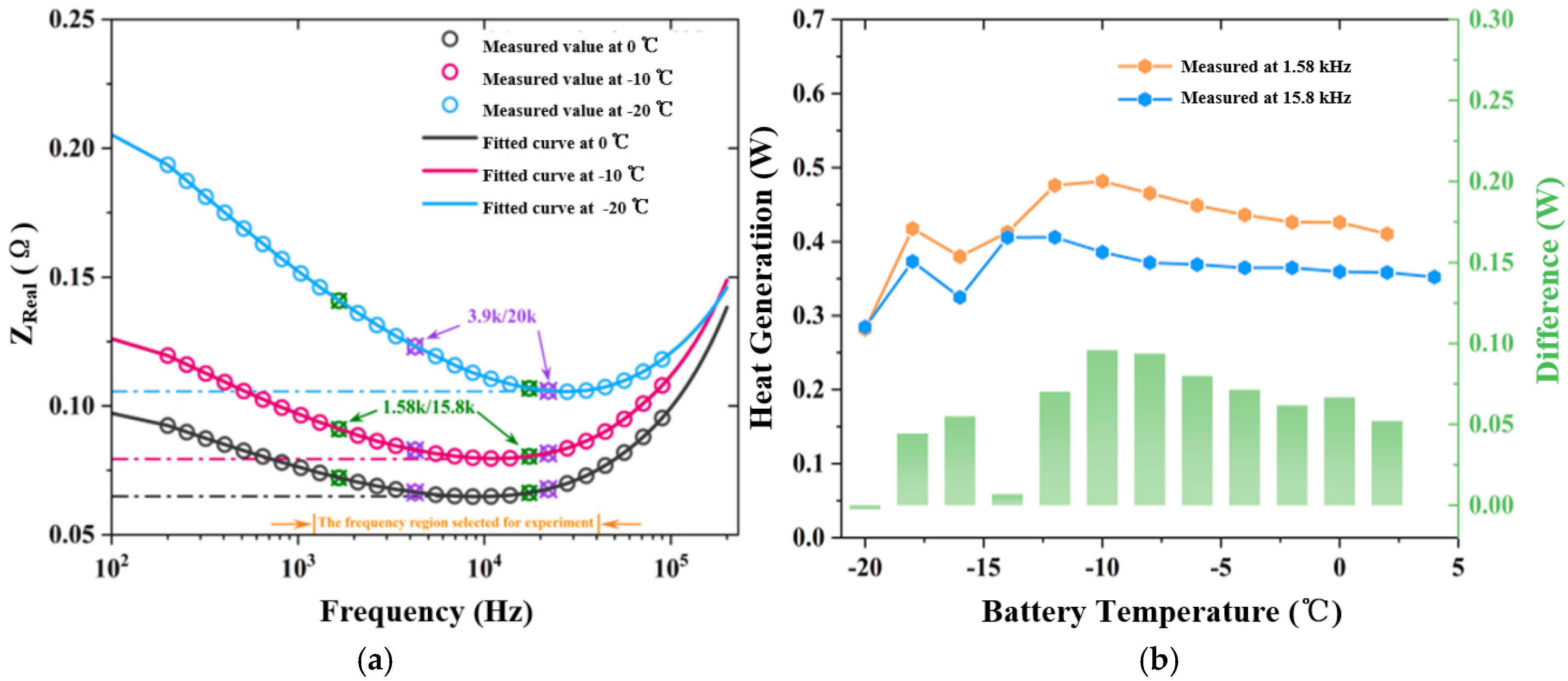
4.1. Calculation of Heat-Producing Power of LIBs Under High-Frequency Ripple Current Excitation

When there is contact impedance in the charge–discharge circuit of the battery, the overall thermal production power is shown in Equation (20).
P s u m = P b + P c o n t a c t = P b + I r m s 2 Z c o n t a c t
where P s u m is the measured total heat-production power, the unit is W; P b is the heat-production power of the battery, the unit is W; P c o n t a c t is the heat-production power of the contact impedance, the unit is W; Z c o n t a c t is the contact impedance, the unit is Ω; and I r m s is the rms value of the high-frequency current, the unit is A.
The contact impedance can be calculated by Experiment 1 and is given by Equation (21):
Z c o n t a c t = P s u m 1 P b 1 I r m s 1 2
where P s u m 1 is the total heat-production power measured in Experiment 1, the unit is W; P b 1 is the heat-production power of the battery in Experiment 1, the unit is W; and I r m s 1 is the rms value of the high-frequency current in Experiment 1, the unit is A.

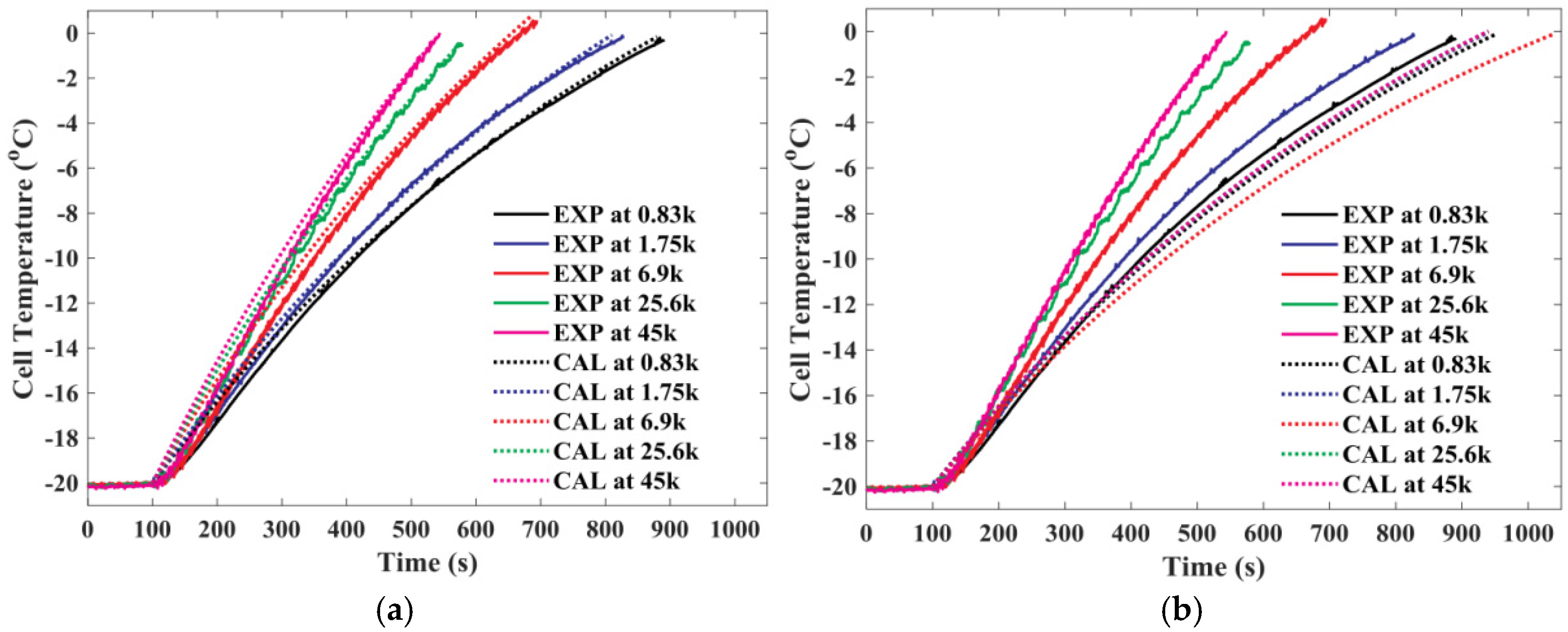
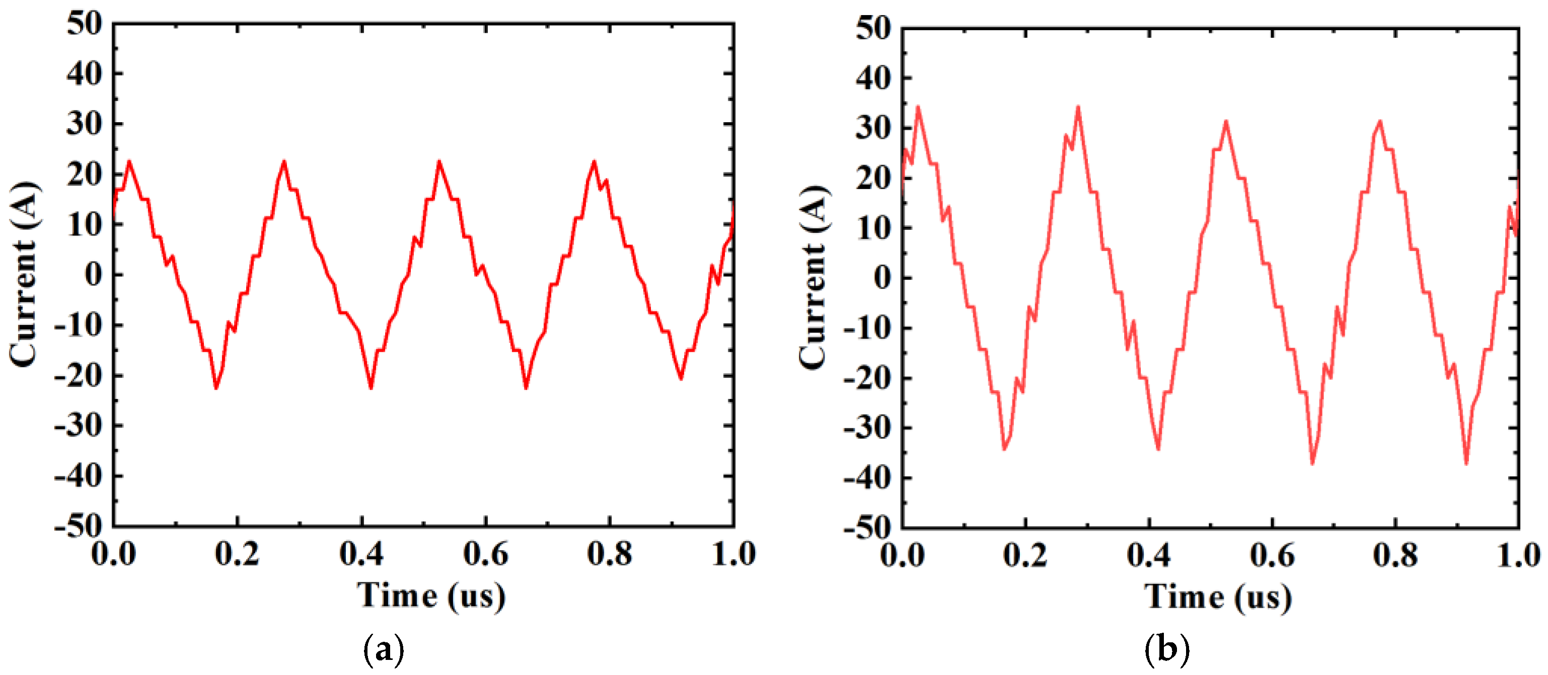
4.2. Heat Production Test of Lithium-Ion Battery Under High-Frequency Ripple Current Excitation

The battery was placed in the isothermal calorimeter for testing, and the results of Experiments 1, 3, and 5 are shown in Table 4. The full names of the items in the table, from the first to the last column, are ‘Serial number’, Measured value of total heat-production power’, ‘Theoretical calculation of heating power’, ‘RMS value of high-frequency current’, ‘The calculated heat-generating power of contact impedance’, ‘Wire connection methods’, and ’Contact impedance obtained by converting heat-generating power to current rms value’.
The contact impedance parameters calculated in Table 4 were replaced in Experiments 2, 4, and 6 for verification, as shown in Table 5. The full names of the items in the table, from the first to the last column, are ‘Serial number’, ’Measured value of total heat-production power’, ‘Theoretical calculation of heating power’, ‘Contact impedance between wire and battery’, ‘Contact impedance thermal power’, ‘Battery heat-production power after removal of contact impedance’, ‘Relative error between theoretically calculated and measured values of battery heat production’, and ‘Relative error between theoretically calculated and measured values of battery heat production after considering contact impedance’.
The calculated impedance is substituted into the second experiment connecting the same frequency and the power line, and the results of the contact impedance are obtained, as shown in Equation (22).
P b 2 c a l = P s u m 2 I r m s 2 2 Z c o n t a c t
where P b 2 c a l is the calculated heat-production power in Experiment 2 after removing the contact impedance; P s u m 2 is the total heat-production power in Experiment 2, and the unit is W.
With the contact impedance taken into account, the measured values of the battery heat-production power for Experiments 2, 4, and 6 were calculated and the relative error was calculated with the theoretical heat-production power obtained using Equation (21).
The contact impedance calculated using Experiment 1 is 0.844 mΩ, and substituting it into Equation (22), the battery thermal power after removing the heating power of contact impedance in Experiment 2 is 0.231 W. The relative errors between the theoretically calculated and measured battery thermal power before and after considering the contact impedance are 109.8% and 20.6%, respectively.
Similarly, using the contact impedance of 2.392 mΩ calculated in Experiment 3 and substituting it into Experiment 4, the relative errors between the theoretically calculated and measured values of the battery thermal power before and after considering the contact impedance are 181.4% and −14.2%, respectively.
After switching to two bundles of power cables to connect the battery, the contact impedance calculated using Experiment 5 is 1.1568 mΩ, which is substituted into Experiment 6, and the relative errors between the theoretically calculated and measured values of the battery thermal power before and after considering the contact impedance are 107.7% and −15.8%, respectively.
Since the internal resistance of this battery is small, the contact impedance will have a greater impact on the total heat production, after removing the contact impedance heat production, the error between the theoretical value and the measured value is greatly reduced, and the calculation of the heat production of the battery is more accurate.
In conclusion, after excluding the interference of contact impedance, the error of the heat-production model of lithium-ion battery under high-frequency ripple current excitation is significantly reduced, and the fitting accuracy of the measurement results and the calculation results of the heat-production model based on linear superposition is high, which makes the battery heat-production model under high-frequency ripple current excitation more accurate.

5. Comparative Study of Low-Temperature Self-Heating Methods

5.1. Calculation of the Minimum Self-Heating Power Required for LIBs at Low Temperatures

In the previous section, by excluding the effect of contact impedance heating, an accurate model of battery heat production under high-frequency ripple current is established, and it can also be seen that the heat-production power of this battery is small due to low high-frequency internal resistance, and if the battery is self-heated using a low-temperature self-impedance heating technique, a larger peak-to-peak high-frequency ripple current is required, which will increase the size, weight, and other parameters of the device.
With the progress of the battery manufacturing process, large-capacity, low internal resistance LIBs have become the new normal. As can be seen from Equation (16), under the condition of the same heat transfer coefficient, the increase in the size of the battery will increase its heat transfer area, which will lead to the heat-dissipation power of the battery becoming larger. In the same frequency and amplitude of high-frequency current excitation, the internal resistance of the battery decreases will lead to a reduction in the power of heat production. This will affect the selection of low-temperature self-heating schemes for batteries of different sizes and internal resistances. Therefore, in this section, based on the thermal equivalent circuit model of the battery established above, we carry out research on the effect of different types of high-frequency ripple current on the heat production of the battery and research on the calculation method of the minimum heating power required under different low-temperature self-heating conditions, so as to provide a theoretical basis for the selection of low-temperature self-heating programs for different types of batteries.
The total duration of the heating process is directly affected by the heating power, so the relationship between the heating power and the total duration of heating needs to be derived. Based on the thermal equivalent circuit model of the lumped type and considering the convective heat dissipation of the battery, when the battery is at a low temperature, the heating process due to self-heating is shown in Equation (23).
P b = P t s + P h t η d c / d c = m C b d T b a t d t + h S h T b a t T a m b η d c / d c
where P b is the total output power of the battery, the unit is W; and η d c / d c is the efficiency of the DC–DC.
Collating Equation (23) results in Equation (24):
d T b a t d t + h S h T b a t m C b = η d c / d c P b + h S h T a m b m C b
The generalized solution of Equation (24) is shown in Equation (25).
T b a t = C exp h S h t m C b + exp h S h t m C b η d c / d c P b + h S h T a m b m C b exp h S h t m C b d t
The initial value of the battery temperature at the beginning of self-heating is T a m b , as shown in Equations (26) and (27):
T a m b = C + η d c / d c P b + h S h T a m b h S h
C = η d c / d c P b h S h
Substituting Equation (27) into Equation (25) yields the solution to the differential equation shown in Equation (28).
T b a t = η d c / d c P b h S h exp h S h t m C b + η d c / d c P b + h S h T a m b h S h
Equation (29) is obtained by shifting the last term on the right side of Equation (28) to the left side of the equation:
h S h T b a t T a m b η d c / d c P b h S h = η d c / d c P b h S h exp h S h t m C b
Both sides of Equation (29) can be multiplied by h S h / η d c / d c P b simultaneously to obtain Equation (30):
h S h T b a t T a m b η d c / d c P b P b = exp h S h t m C b
Taking logarithms with natural constants on both sides of Equation (30) simultaneously gives Equation (31)
ln h S h T b a t T a m b P b η d c / d c P b = h S h t m C b
Collating Equation (31) yields Equation (32):
t = m C b h S h ln 1 1 h S h T b a t T a m b η d c / d c P b

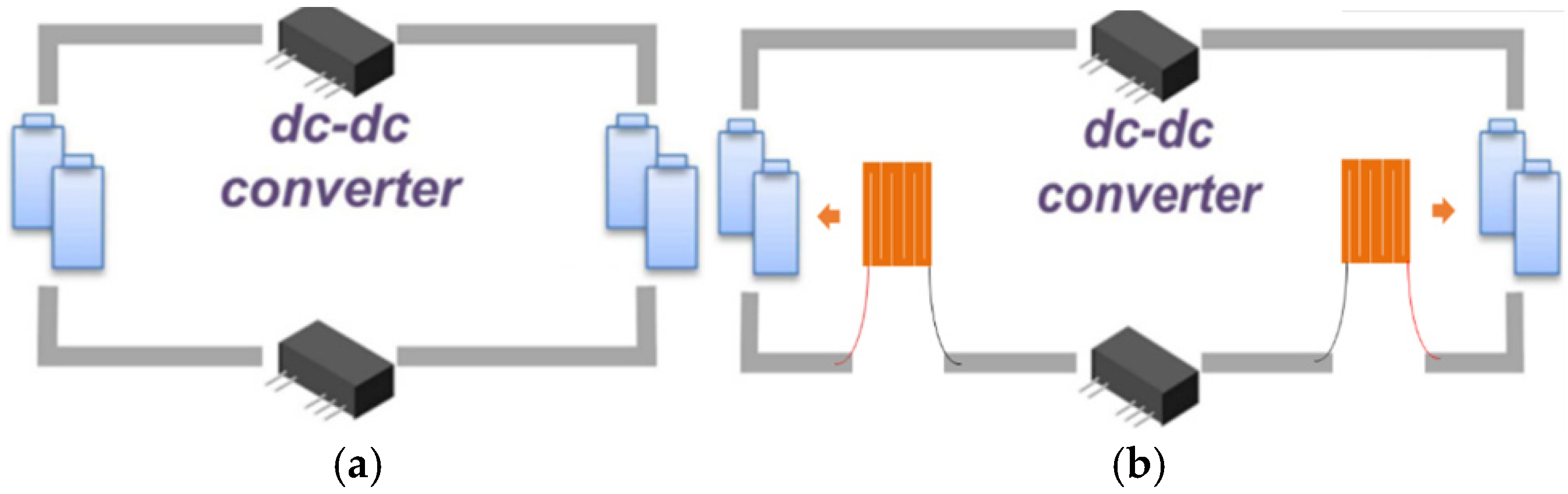
5.2. Preferred Low-Temperature Self-Heating Methods for Different Types of LIBs

Since the low-temperature self-heating problem has a practical background, i.e., heating the battery from an initial temperature to a target temperature within a specified time ( t max ). Based on this, Equation (32) can be converted into an inequality as shown in Equation (33).
t = m C b h S h ln 1 1 h S h T b a t T a m b η d c / d c P b t max
For example, at an ambient temperature of −15 °C, the battery needs to be heated to 0 °C in 600 s (10 min), and assuming that the heat-production power of the battery is very close to the same in this temperature interval, we have Equation (34):
P b T b a t T a m b h S h η d c / d c 1 exp t max h S h m C b = 15 h S h η d c / d c 1 exp 600 h S h m C b
When the heating power of the battery satisfies Equation (30), this battery is able to be heated from −15 °C to 0 °C in 10 min. Substituting the battery and environment parameters used in this chapter into Equations (5)–(40), which h S h is 4.2032 W·K−1, m is 0.6945 kg, and C b is 1253 J·kg−1·K−1, we have Equation (35):
P b 15 × 4.2032 0.93 × 1 exp 600 × 4.2032 0.6945 × 1253 = 25 . 36 W
For example, data reported by Li et al. (2019) are used to validate the proposed calculation method. In the literature, a 1 kHz sinusoidal current is used to self-impedance heat the battery from −20 °C to −10 °C in 3000 s. Its average internal resistance at low temperature is 38 mΩ, the convective heat transfer coefficient h is equal to 15.21 W·m−2·K−1, and the specific heat capacity is 994.65 (J·kg−1·K−1) with an area of 4.18 × 10⁻³ m−2. Since this study uses high-frequency current generated from an external power supply, there is no efficiency loss of the converter, so η d c / d c is set to 1. The minimum power required can be calculated by Equation (31) to be 0.69 W, and then using the value of the internal resistance, the minimum amplitude of the required sinusoidal current is converted to be 5.83 A, which is a smaller difference from the 6.45 A used in the literature, which verifies the accuracy of the calculation method proposed in this paper.
Laying the aerogel insulation felt on the inside of the insulation box, the convective heat transfer coefficient inside its battery box was measured to be about 2.2 W·m−2·K−1, as shown in Figure 11. The battery in Figure 11 is the #3 battery in Table 6, which is a laboratory-owned battery, as is the #8 battery. Based on the heating scheme in Figure 1a, the minimum power required for these batteries under the same low-temperature self-heating conditions was calculated by Equation (30) for multiple battery parameters considering a power electronics efficiency of 93%, and the low-temperature self-heating conditions were as follows: within 10 min (600 s) and within the insulated environment shown in Figure 11, using a 1 kHz positive and negative square wave high-frequency currents for self-impedance heating.
Calculations of the minimum power and the amplitude of the corresponding current are shown in Table 6. The full names of the items in the table, from the first to the last column, are ‘Battery number’, ’Battery Types’, ’Rated capacity’, ‘Mass’, ‘Specific heat capacity’, ‘Convective heat transfer coefficient (CHTC)’, ‘Ambition temperature’, ‘Battery temperature’, ‘Minimum power required’, ‘Average real part impedance of the battery at 1 kHz at low temperature’, and ‘Minimum required positive and negative alternating square wave pulse current values’.
In this case, the parameters of multiple batteries were obtained from the literature. Since the specific heat capacity of the batteries is not listed in the literature [30], the range of heating power required was calculated based on the range of specific heat capacities of similar batteries. In order to differentiate the energy and power performance of different batteries, the specific energy of all batteries was calculated and their internal resistance parameters were listed as shown in Table 7. The full names of the items in the table, from the first to the last column, are ‘Battery number’, ’Battery Types’, ’Rated capacity (Ah)’, ‘Mass (kg)’, ‘Energy density per unit of volume (Wh/L)’, ‘Energy density per unit mass (Wh/kg)’, ‘Average real part impedance of the battery at 1 kHz at low temperature (mΩ)’, and ‘Minimum required positive and negative alternating square wave pulse current values’.
From Table 6 and Table 7, it can be seen that the energy density of the No. 6 18650 battery is the highest, and at the same time, its internal resistance is the highest, which is a high specific power battery. The remaining five kinds are due to the difference in process and material. Its energy density is different, but the internal resistance is relatively small, in the range of 30~50 mΩ, which can be considered a high specific power battery. For the six kinds of 18650 batteries using 1 kHz high-frequency current heating, the required current multiplier is small, an average of 2.49 C. The smallest required current multiplier is the highest specific energy of No. 6 batteries, 1.53 C (4.43 A); the highest for the No. 2 18650 batteries, 2.86 C (7.16 A). For the No. 7 and No. 8, two kinds of high-ratio power batteries, the required current multiplier is very large, respectively, 10.76 C and 9.01 C, which is 7.03 times and 5.89 times the required multiplier of No. 6 batteries. The No. 9 LiFePO4 battery is energy-power balanced, although the required current multiplier is small, the 100 A high-frequency square-wave current is still difficult to realize, so the authors in the study used a low-frequency square wave current heating.
As can be seen from Table 6, there is a large difference in the current multiplier when different types of batteries are subjected to low-temperature self-heating, and the increase in d i / d t not only increases the weight and size of the device but also increases the current commutation at the same high-frequency square-wave frequency, which increases the difficulty of designing and controlling the device and poses a challenge to the engineering of this method. Therefore, it is necessary to add heating pads to the original scheme to generate additional heat, as shown in Figure 1b. The scheme in Figure 1b is known as the internal and external heating method, which is to fix the external heating element on the surface of the battery, using the battery as the only energy source, and generating a high-frequency current through the power electronics to heat the external heating element, and the battery produces a certain amount of heat under its own impedance so that ultimately the battery warms up under the combined effect of the two kinds of impedance heat production, internal and external.
By calculation, the convective heat transfer coefficient of the LTO 25 Ah battery in the adiabatic environment of Figure 11 is 4.2032 W·K−1. When heated aluminum foil with a resistance value of 34.5 mΩ is used, curves for different current amplitudes versus total heating time can be obtained, as shown in Figure 12.
From Figure 12, it can be seen that the current amplitude required for low-temperature self-heating decreases significantly after the addition of an external heating element. When the current amplitude is 10.51 A, the total heating time is 281.11 min; when the current amplitude is 13.20 A, the total heating time is 60 min; when the current amplitude is 16.81 A, the total heating time is 30 min; and when the current amplitude is 26.93 A, the total heating time is 10 min. Under the same low-temperature self-heating requirement, the current required to achieve the heating purpose in 10 min is 225.22 A. The internal and external heating method reduces the current amplitude by 88.04%, which significantly reduces the engineering difficulty of the self-heating solution and the weight and size of the equipment.
Since the additional heated foil would add weight to the battery, the added weight is evaluated: with an aluminum density of 2.7 g/cm3, the weight of one heated foil is approximately 8.208 g. However, in engineering design, since the heating foil needs to be tightly affixed to the battery, additional materials will be used and the weight will increase slightly, which should be taken into extra consideration in practical applications.
For the 18650 batteries in Table 6, its average internal resistance is 48.5 mΩ, and due to the reduction of the accessible area, the internal resistance of the heating foil will also be reduced, assuming that the heating foil can be uniformly affixed to the surface of the battery. When the aluminum foil length is 65 mm and the width is 18 mm, the internal resistance is only 1.36 mΩ. The increase of the heating power is extremely limited. Therefore, for the 18650 battery, it is more suitable to use only its own impedance for low-temperature self-heating under high-frequency current.
For the 18650 battery and the LTO 25 Ah battery used in this paper, the current required for internal and external self-heating and self-impedance heating is converted into the corresponding multiplier value as shown in Figure 13, which shows that there is a big difference in the current multiplier required for two kinds of batteries in different self-heating programs.
In summary, for large-capacity high-ratio power batteries, priority should be given to the use of high-frequency current inside and outside the heating program. For large-capacity high-ratio energy batteries, with their own impedance heating, although the current multiplier is small, the current amplitude is large. It should be assessed for the difficulty of engineering the use of a suitable program. For small-capacity LIBs, only its own impedance in the high-frequency current of the heat can meet the needs of the battery’s low-temperature and rapid self-heating. Heating needs and high specific energy batteries require a relatively small current multiplier. In addition, using the same size of battery, under the same conditions of the total energy of the group, the high ratio energy battery due to the small size of the group means its heat dissipation area is smaller. The self-impedance heating program will be more advantageous.

6. Conclusions

This paper develops an accurate thermal model for LIBs under high-frequency ripple current excitation, aiming to address the significant discrepancies in heat generation calculation and measurement during self-heating. Based on this model, a calculation method for the minimum heating power required for low-temperature self-heating is presented, and a comparative study of different battery types is conducted to evaluate low-temperature self-heating schemes.
To address the large difference in heat generation, six experiments with varying frequencies, high-frequency current amplitudes, and contact impedances were designed. By considering the effect of contact impedance heat generation, the error between measurement and model results is reduced, enhancing the model’s accuracy.
The relationship between low-temperature self-heating time, temperature range, battery parameters, and heat-producing power is derived, and a method for calculating the minimum heating power is proposed and verified. Using battery parameters from different literature, the heating power required for different types of batteries to self-heat at high-frequency currents is calculated. It is found that the current multiplication required for high-capacity high-power batteries using the self-impedance heating scheme increases significantly compared to small-capacity and high-energy batteries. The current required for high-power LTO batteries is much higher than that for high-ratio-energy 18650 batteries, increasing the device’s size and weight.
By comparing the current values for self-impedance heating and internal/external heating schemes, it is revealed that for large-capacity batteries with low internal resistance, the internal/external heating scheme reduces the current amplitude significantly. Suggestions are provided for choosing low-temperature self-heating schemes based on different battery types: for high-capacity high-ratio power batteries, the high-frequency internal/external heating scheme is preferred; for high-capacity high-energy batteries, self-impedance heating with a larger current amplitude may be considered; for small-capacity LIBs, self-impedance heating under high-frequency currents is advisable. For small-capacity LIBs, only the impedance in high-frequency current heat generation can meet the needs of low-temperature rapid self-heating, and the current multiplier for high-ratio energy batteries is relatively smaller. This provides a basis for selecting heating schemes for different types of LIBs at low temperatures. This paper contributes to a better understanding of lithium-ion battery thermal behavior and the optimization of low-temperature self-heating strategies.
The research in this paper provides more accurate LIB thermal modeling at high-frequency currents, which supports low-temperature heating applications and provides guidance for the selection of low-temperature heating schemes for different types of batteries. It provides a basis for the next development of thermal modeling of LIB modules under high-frequency current and research on low-temperature heating applications of LIB modules.

Author Contributions

H.L.: Conceptualization, Methodology, Software, Formal Analysis, Writing—original draft. J.C.: Visualization, Funding Acquisition. Y.M.: Methodology, Software. W.L.: Project Administration. L.T.: Writing—review and editing. B.L.: Conceptualization, Supervision. All authors have read and agreed to the published version of the manuscript.

Funding

This work is supported by the Science Foundation of the Chinese Academy of Railway Sciences, grant number 2022YJ306.

Data Availability Statement

The data presented in this study are available upon request from the corresponding author. Data are not disclosed because the relevant data are in the process of being used in other studies.

Conflicts of Interest

All authors are affiliated with the company China Academy of Railway Sciences Corporation Limited and the company Beijing Zongheng Electro-Mechanical Technology Co., Ltd. Authors declare that the research was conducted in the absence of any commercial or financial relationships that could be construed as a potential conflict of interest.

Abbreviations

Nomenclature DGPCDouble group power cable
ZImpedance valueDCDirect Current
ZrealReal impedance valueLTOLithium-titanate Battery
ZimagImaginary impedance valueSOCState of Charge
PTotal power of the batterySubscript
QHeat producedavethe average voltage
ICharge/discharge currentambambient temperature
UocvOpen circuit voltagerereversible reaction
UOutput voltageheheat exchange
ηEfficiencyhcchange of the heat capacity
Acronyms memixing effect
DC-DCDirect Current to Direct Current converterhaheat build-up accumulated
PCPersonal computershtheat exchange
RLResistance-InductanceocvOpen circuit voltage
LIBLithium-ion batteryomOhmic internal resistance
LIBsLithium-ion batteriespterminal voltage
EISElectrochemical impedance spectrumbatBattery
RMSRoot Mean SquareambAmbient
EXPExperience modelhfhigh-frequency
CALTheoretical calculationrealReal part of impedance
EISElectrochemical impedance spectrumimagImaginary part of impedance
ACAlternating CurrentimagImaginary part of impedance
SGPCSingle group power cablepephase change
CHTCConvective heat transfer coefficient

References

  1. Tomaszewska, A.; Chu, Z.; Feng, X.; O’Kane, S.; Liu, X.; Chen, J.; Ji, C.; Endler, E.; Li, R.; Liu, L.; et al. Lithium-ion battery fast charging: A review. ETransportation 2019, 1, 100011. [Google Scholar] [CrossRef]
  2. Ruan, H.; Barreras, J.V.; Steinhardt, M.; Jossen, A.; Offer, G.J.; Wu, B. The heating triangle: A quantitative review of self-heating methods for lithium-ion batteries at low temperatures. J. Power Sources 2023, 581, 233484. [Google Scholar] [CrossRef]
  3. Yang, X.-G.; Zhang, G.; Ge, S.; Wang, C.-Y. Fast charging of lithium-ion batteries at all temperatures. Proc. Natl. Acad. Sci. USA 2018, 115, 7266–7271. [Google Scholar] [CrossRef] [PubMed]
  4. Zhang, J.; Ge, H.; Li, Z.; Ding, Z. Internal heating of lithium-ion batteries using alternating current based on the heat generation model in frequency domain. J. Power Sources 2015, 273, 1030–1037. [Google Scholar] [CrossRef]
  5. Zhu, J.; Sun, Z.; Wei, X.; Dai, H.; Gu, W. Experimental investigations of an AC pulse heating method for vehicular high power lithium-ion batteries at subzero temperatures. J. Power Sources 2017, 367, 145–157. [Google Scholar] [CrossRef]
  6. Qu, Z.G.; Jiang, Z.Y.; Wang, Q. Experimental study on pulse self–heating of lithium–ion battery at low temperature. Int. J. Heat Mass Transf. 2019, 135, 696–705. [Google Scholar] [CrossRef]
  7. Ji, Y.; Wang, C.Y. Heating strategies for Li-ion batteries operated from subzero temperatures. Electrochim. Acta 2013, 107, 664–674. [Google Scholar] [CrossRef]
  8. Ruan, H.; Sun, B.; Jiang, J.; Su, X.; He, X.; Ma, S.; Gao, W. Optimal switching temperature for multi-objective heated-charging of lithium-ion batteries at subzero temperatures. J. Power Sources 2023, 562, 232775. [Google Scholar] [CrossRef]
  9. Hu, X.; Li, S.; Peng, H. A comparative study of equivalent circuit models for Li-ion batteries. J. Power Sources 2012, 198, 359–367. [Google Scholar] [CrossRef]
  10. Juang, L.W.; Kollmeyer, P.J.; Jahns, T.M.; Lorenz, R.D. Improved nonlinear model for electrode voltage–current relationship for more consistent online battery system identification. IEEE Trans. Ind. Appl. 2013, 49, 1480–1488. [Google Scholar] [CrossRef]
  11. Liu, S.; Jiang, J.; Shi, W.; Ma, Z.; Wang, L.Y.; Guo, H. Butler–volmer-equation-based electrical model for high-power lithium titanate batteries used in electric vehicles. IEEE Trans. Ind. Electron. 2015, 62, 7557–7568. [Google Scholar] [CrossRef]
  12. Chen, A.; Zhang, W.; Zhang, C.; Huang, W.; Liu, S. A temperature and current rate adaptive model for high-power lithium-titanate batteries used in electric vehicles. IEEE Trans. Ind. Electron. 2019, 67, 9492–9502. [Google Scholar] [CrossRef]
  13. Li, H.; Jiang, J.; Zhang, W.; Zhang, L.; Yang, Y.; Chen, A.; Fan, X. High-accuracy parameters identification of non-linear electrical model for high-energy lithium-ion capacitor. IEEE Trans. Intell. Transp. Syst. 2020, 22, 651–660. [Google Scholar] [CrossRef]
  14. Sun, B.; He, X.; Zhang, W.; Ruan, H.; Su, X.; Jiang, J. Study of parameters identification method of Li-ion battery model for EV power profile based on transient characteristics data. IEEE Trans. Intell. Transp. Syst. 2020, 22, 661–672. [Google Scholar] [CrossRef]
  15. Ruan, H.; Sun, B.; Cruden, A.; Zhu, T.; Jiang, J.; He, X.; Su, X.; Ghoniem, E. Optimal external heating resistance enabling rapid compound self-heating for lithium-ion batteries at low temperatures. Appl. Therm. Eng. 2022, 200, 117536. [Google Scholar] [CrossRef]
  16. Shang, Y.; Xia, B.; Cui, N.; Zhang, C.; Mi, C.C. An automotive onboard AC heater without external power supplies for lithium-ion batteries at low temperatures. IEEE Trans. Power Electron. 2017, 33, 7759–7769. [Google Scholar] [CrossRef]
  17. Shang, Y.; Zhu, C.; Lu, G.; Zhang, Q.; Cui, N.; Zhang, C. Modeling and analysis of high-frequency alternating-current heating for lithium-ion batteries under low-temperature operations. J. Power Sources 2020, 450, 227435. [Google Scholar] [CrossRef]
  18. Hu, Z.; Liu, F.; Chen, P.; Xie, C.; Huang, M.; Hu, S.; Lu, S. Experimental study on the mechanism of frequency-dependent heat in AC preheating of lithium-ion battery at low temperature. Appl. Therm. Eng. 2022, 214, 118860. [Google Scholar] [CrossRef]
  19. Li, J.-Q.; Sun, D. Lithium-ion batteries modeling and optimization strategies for sinusoidal alternating current heating at low temperature. Energy Procedia 2018, 152, 562–567. [Google Scholar] [CrossRef]
  20. Li, J.; Sun, D.; Chai, Z.; Jiang, H.; Sun, C. Sinusoidal alternating current heating strategy and optimization of lithium-ion batteries with a thermo-electric coupled model. Energy 2019, 186, 115798. [Google Scholar] [CrossRef]
  21. Fan, X.; Zhang, W.; Wang, Z.; An, F.; Li, H.; Jiang, J. Simplified battery pack modeling considering inconsistency and evolution of current distribution. IEEE Trans. Intell. Transp. Syst. 2020, 22, 630–639. [Google Scholar] [CrossRef]
  22. Zhang, J.; Ci, S.; Sharif, H.; Alahmad, M. Modeling discharge behavior of multicell battery. IEEE Trans. Energy Convers. 2010, 25, 1133–1141. [Google Scholar] [CrossRef]
  23. Shi, W.; Hu, X.; Jin, C.; Jiang, J.; Zhang, Y.; Yip, T. Effects of imbalanced currents on large-format LiFePO4/graphite batteries systems connected in parallel. J. Power Sources 2016, 313, 198–204. [Google Scholar] [CrossRef]
  24. Sung, W.; Hwang, D.S.; Jeong, B.-J.; Lee, J.; Kwon, T. Electrochemical battery model and its parameter estimator for use in a battery management system of plug-in hybrid electric vehicles. Int. J. Automot. Technol. 2016, 17, 493–508. [Google Scholar] [CrossRef]
  25. Ruan, H.; Jiang, J.; Sun, B.; Zhang, W.; Gao, W.; Wang, L.Y.; Ma, Z. A rapid low-temperature internal heating strategy with optimal frequency based on constant polarization voltage for lithium-ion batteries. Appl. Energy 2016, 177, 771–782. [Google Scholar] [CrossRef]
  26. Ruan, H.; Jiang, J.; Ju, Q.; Sun, B.; Cheng, G. A reduced wide-temperature-range electro-thermal model and thermal parameters determination for lithium-ion batteries. Energy Procedia 2017, 105, 805–810. [Google Scholar] [CrossRef]
  27. Waldmann, T.; Wilka, M.; Kasper, M.; Fleischhammer, M.; Wohlfahrt-Mehrens, M. Temperature dependent ageing mechanisms in Lithium-ion batteries–A Post-Mortem study. J. Power Sources 2014, 262, 129–135. [Google Scholar] [CrossRef]
  28. Jiang, J.; Ruan, H.; Sun, B.; Wang, L.; Gao, W.; Zhang, W. A low-temperature internal heating strategy without lifetime reduction for large-size automotive lithium-ion battery pack. Appl. Energy 2018, 230, 257–266. [Google Scholar] [CrossRef]
  29. Kizilel, R.; Lateef, A.; Sabbah, R.; Farid, M.; Selman, J.; Al-Hallaj, S. Passive control of temperature excursion and uniformity in high-energy Li-ion battery packs at high current and ambient temperature. J. Power Sources 2008, 183, 370–375. [Google Scholar] [CrossRef]
  30. Ruan, H.; Sun, B.; Zhang, W.; Su, X.; He, X. Quantitative analysis of performance decrease and fast-charging limitation for lithium-ion batteries at low temperature based on the electrochemical model. IEEE Trans. Intell. Transp. Syst. 2020, 22, 640–650. [Google Scholar] [CrossRef]
Figure 1. Two self-heating methods using DC–DC converters: (a) self-impedance heating [7] and (b) internal and external heating [15].
Batteries 10 00419 g001
Figure 2. Results of correction for temperature variation of LIBs using empirical models [17]: (a) The proposed thermoelectric model considering the heat generation of the charge transport, (b) The conventional heating model without the heat generation of the charge transport.
Batteries 10 00419 g002
Figure 3. The EIS graphs obtained in a warm environment [18]: (a) EIS data of the battery, (b) Test results of battery heating using high-frequency current at 1.58 kHz and 15 kHz.
Batteries 10 00419 g003
Figure 4. Different low-temperature self-heating solutions for different batteries: (a) self-heating solution for the 18650 battery [25], (b) self-heating solution for pouch batteries with large capacity [28].
Batteries 10 00419 g004
Figure 5. Experimental platform and the procedure: (a) Battery impedance parameter test platform, (b) Procedure of experimental test.
Batteries 10 00419 g005
Figure 6. Battery heat test platform with high-frequency current ripple excitation.
Batteries 10 00419 g006
Figure 7. The topology of the DC–DC converter.
Batteries 10 00419 g007
Figure 8. Current waveforms for Experiments 1–4: (a) 4 kHz—45.2 A, (b) 4 kHz—68.6 A, (c) 10 kHz—28.4 A, (d) 10 kHz—34.4 A.
Batteries 10 00419 g008aBatteries 10 00419 g008b
Figure 9. EIS of batteries at different SOC points at 25 °C.
Batteries 10 00419 g009
Figure 10. The variation curve of the real impedance of the battery at different SOC points with frequency at 25 °C.
Batteries 10 00419 g010
Figure 11. Schematic diagram of the thermal insulation: (a) Inside of the thermal insulation, (b) Surface of the thermal insulation.
Batteries 10 00419 g011
Figure 12. The curve of the variation of the duration in heating with the amplitude of the heating current under the internal and external heating scheme.
Batteries 10 00419 g012
Figure 13. The curves of the total heating time with current rates for the two batteries under different schemes.
Batteries 10 00419 g013
Table 1. Results of impedance calculations.
Frequency
(kHz)
Impedance
(Ω)
RMS Value
(A)
Heating Power of
(W)
Theoretical Calculation
(W)
Measured Value
(W)
Gap
(W)
Real Impedance Difference
(Ω)
1.58 kHz0.1301.40.014120.141520.280.138470.1413
20.02880.260.550.290.145
15.8 kHz0.1051.6250.04750.18610.280.09390.0711
2.20.0870.2970.5250.02280.0942
Table 2. Basic Parameters of the Tested LTO Battery.
Battery ParametersCharacteristics
Anode materialLTO
Cathode materialNMC + LiCoO2
Nominal capacity25.0 Ah
Nominal voltage2.35 V
Charge conditionCC 25 A, 2.8 V cutoff
Discharge conditionCC 25 A, 1.5 V cutoff
Table 3. Experimental design of lithium-ion battery heat-generation power under high-frequency ripple current excitation.
Serial NumberType of
High-Frequency Current
Frequency of High-Frequency Current (kHz)Peak—Peak Value of High-Frequency Current (A)RMS Value of High-Frequency Current (A)Wire Connection MethodsThe Measured
Impedance of the DC Contact (mΩ)
1Triangular Wave445.213.15SGPC0.448
2Triangular Wave468.619.97SGPC
3Triangular Wave1028.47.89SGPC
4Triangular Wave1034.49.61SGPC
5Triangular Wave1028.47.89DGPC0.196
6Triangular Wave1034.49.61DGPC
Table 4. Experimental results on the heating power of LIBs under high-frequency ripple current excitation.
Serial NumberMeasured Value (W)Theoretical
Calculation (W)
RMS Value (A)The Calculated
Impedance (W)
Wire Connection MethodsContact
Impedance (mΩ)
10.2570.11913.150.138SGPC0.844
30.2280.0797.890.149SGPCe2.392
50.1470.0727.890.075SGPC1.157
Table 5. Experimental results of the heating power of LIBs under high-frequency ripple current excitation.
Serial NumberMeasured ValueTheoretical
Calculation (W)
Contact
Impedance (mΩ)
Contact
Impedance
Thermal Power (W)
Production Power After Removal of Contact Impedance
(W)
Relative Error
(%)
Relative Error
Between After
Considering
Contact Impedance
(%)
20.5790.2760.8440.3020.242109.8−12.3
40.3180.1132.3920.2050.097181.4−14.2
60.2410.1161.1570.1250.134107.715.8
Table 6. Current boundary conditions for the completion of low-temperature self-heating in the specified time for different batteries.
Battery NumberBattery TypesRated Capacity
(Ah)
Mass (kg)Specific Heat
Capacity (J·kg−1·K−1)
CHTC (m2)Ambition
Temperature (℃)
Battery Temperature
(℃)
Minimum
Power Required (W)
Average Real
Part Impedance (mΩ)
Minimum Required Pulse Current Values
118650 NCM [20]2.150.045994.654.18 × 10−3−1501.28356.04 A
(2.81 C)
218650 NCM [17]2.50.04617204.18 × 10−3−1502.20437.16 A
(2.86 C)
318650 NCM (Figure 11 in this paper)2.60.04810484.18 × 10−3−1501.43306.90 A
(2.65 C)
418650 NCM [25]2.750.04511474.18 × 10−3−1501.46306.98 A
(2.54 C)
518650 NCM [5]2.80.04617204.18 × 10−3−1502.20457.00 A
(2.50 C)
618650 NCM [18]2.90.04716184.18 × 10−3−1502.121084.43 A
(1.53 C)
7Pouch battery LTO [26]80.300927.570.037−1508.161.186.11 A
(10.76 C)
8Pouch battery LTO (Table 2 in this paper)250.69512530.108−15025.360.5225.22 A
(9.01 C)
9Pouch battery LiFePO4 [5]300.6751000~1500
(hypothetical)
0.05679−15019.17~28.24297.91–118.82 A
(3.26~3.96 C)
Table 7. Specific energy and power parameters of different batteries.
Battery NumberBattery TypesRated Capacity (Ah)Mass (kg)Energy Density (Wh/L)Energy Density (Wh/kg)Average real part Impedance of the Battery (mΩ)Minimum
Required Current Values
118650 NCM [20]2.150.045467.94164.68356.04 A (2.81 C)
218650 NCM [17]2.50.046559.23201.09437.16 A (2.86 C)
318650 NCM (Figure 11 in this paper)2.60.048581.60200.42306.90 A (2.65 C)
418650 NCM [25]2.750.045598.53220.00306.98 A (2.54 C)
518650 NCM [5]2.80.046609.41219.13457.00 A (2.50 C)
618650 NCM [18]2.90.047631.18222.131084.43 A (1.53 C)
7Pouch battery LTO [26]80.300207.4996.001.186.11 A (10.76 C)
8Pouch battery LTO (Table 2 in this paper)250.695196.5282.790.5225.22 A (9.01 C)
9Pouch battery LiFePO4 [5]300.675307.84142.22297.91–118.82 A
(3.26~3.96 C)
Disclaimer/Publisher’s Note: The statements, opinions and data contained in all publications are solely those of the individual author(s) and contributor(s) and not of MDPI and/or the editor(s). MDPI and/or the editor(s) disclaim responsibility for any injury to people or property resulting from any ideas, methods, instructions or products referred to in the content.

