Article

Fine-Tuning Cathode Performance: The Influence of Argon Deposition Pressure on LiMn2O4 Thin Film Electrochemistry for Li-Ion Batteries

by
Fabián Ambriz-Vargas
1,
Raquel Garza-Hernández
1,*,
José Salvador Martínez-Flores
1,
Francisco Servando Aguirre-Tostado
2,3,
Eduardo Martínez-Guerra
2 and
Manuel Quevedo-López
3
1
Centro de Investigaciones en Óptica, A.C., Loma del Bosque 115, Col. Lomas del Campestre, León C.P. 37150, Guanajuato, Mexico
2
Centro de Investigación en Materiales Avanzados, S.C. (CIMAV Subsede Monterrey), Alianza Norte 202, Parque de Investigación e Innovación Tecnológica, Apodaca C.P. 66628, Nuevo León, Mexico
3
Department of Materials Science & Engineering, The University of Texas at Dallas, Richardson, TX 75080, USA
*
Author to whom correspondence should be addressed.
Batteries 2024, 10(12), 449; https://doi.org/10.3390/batteries10120449
Submission received: 14 November 2024 / Revised: 7 December 2024 / Accepted: 11 December 2024 / Published: 18 December 2024

Abstract

:
Lithium manganese oxide (LiMn2O4) is an effective cathode material for high-capacity lithium-ion (Li-ion) batteries. Therefore, to optimize battery efficiency, it is essential to understand how sputtering deposition conditions affect the quality and performance of LiMn2O4. This research examines how argon deposition pressure affects the stoichiometric characteristics and electrochemical performance of LiMn2O4. The study finds that changing argon deposition pressures, from a low of 5 mTorr to a high of 30 mTorr, results in the formation of different coating stoichiometries. At low argon deposition pressures, stoichiometric LiMn2O4 cathode coatings formed, exhibiting the highest discharge capacity of 115 mAh/g. Conversely, at high argon deposition pressures, non-stoichiometric LiMn2O4 with lithium deficiency was produced. These coatings exhibited diminished electrochemical behavior, achieving a discharge capacity of only 70 mAh/g at 5 mTorr. The lack of lithium resulted in a significant reduction in electrochemical performance, indicated by a high surface charge transfer resistance (R2 = 48,529 Ω), which led to a low discharge capacity of 40 mAh/g.

Graphical Abstract

1. Introduction

In today’s Internet of Things (IoT) era, electronic and information technology devices are progressively shrinking in size. Consequently, there is an escalating demand for novel energy storage solutions [1]. Presently, biological/medical devices and self-powered microelectronics typically operate within the millimeter range and rely on energy storage devices in the form of coin cells due to the absence of commercially available cells in smaller sizes [2,3]. Shrinking the size of batteries without compromising their storage capacity presents a formidable challenge, as the battery’s capacity is inherently linked to the dimensions of its active components, namely, the cathode and anode. To optimize the battery’s capacity, it is crucial to use electrodes with a high intrinsic volumetric capacity [4]. Thin-film solid-state batteries emerge as an exemplary solution for achieving miniaturization, as they offer substantial capacity within a compact footprint. For instance, researchers at the University of Illinois have devised a fabrication process yielding a micro-sized lithium-ion battery (0.23 mm3) boasting an impressive energy density of 1260 Wh/L [5].
A solid-state battery featuring a thin-film structure comprises a cathode and anode, with a solid electrolyte replacing the conventional liquid variant [6]. This innovative design offers several advantages. Firstly, it exhibits low electronic resistance at the electrode–electrolyte interface, obviating the necessity for traditional conductive additives such as carbon black. Secondly, the electrode films possess minimal porosity, rendering polymeric binders unnecessary. Lastly, the utilization of a solid electrolyte instead of a liquid one significantly mitigates the risk of chemical electrode decomposition and flammability, thereby enhancing overall safety [6,7]. Thin-film, solid-state batteries operate on a principle similar to that of conventional liquid electrolyte batteries owing to their similar physical structure. Fundamentally, within these batteries, the cathode and anode generate and consume electrons, while the solid-state electrolyte facilitates the movement of lithium cations via an interstitial hopping mechanism [8]. Each internal component must meet specific material requirements to ensure successful charge transfer and ion migration in thin-film, solid-state batteries. Regarding solid-state electrolytes, the garnet Li7La3Zr2O12 oxide material is commonly proposed due to its high ionic conductivity (10−5 S/cm), low electronic conductivity (10−9 S/cm), and structural robustness, which ensures mechanical integrity and facilitates charge carrier migration [8]. Lithium metal serves as an exemplary anode material owing to its high potential (−3.04 vs. NHE) and considerable theoretical capacity (3686 mAh/g), enabling the attainment of the highest achievable voltage [8,9,10]. Cathode materials must possess a high energy density, high rate capability, and superior cycling stability [11]. Three categories of cathode materials are prevalent in thin-film, solid-state batteries: layer-structured, spinel-structured, and olivine-structured. Among these, layered LiCoO2 oxide materials have been commercially successful since 1991, despite safety concerns associated with this cathode type. Delithiated layered cathodes, when paired with organic electrolytes, can instigate exothermic reactions leading to thermal runaway and potential explosion [12]. Cathodes based on spinel materials, such as LiMn2O4, hold significant promise due to their enhanced safety characteristics. Although LiMn2O4 offers a smaller capacity (120 mAh/g) and specific energy (490 Wh/kg) compared to the LiCoO2 cathodes (185 mAh/g and 720 Wh/kg), its safety profile makes it a compelling alternative [13].
LiMn2O4 emerges as an intriguing cathode material possessing unique structural and chemical properties. Within a lithium-ion battery, the cubic phase of LiMn2O4 undergoes lithiation during the discharge process, forming a new phase characterized by tetragonal-LiMnO2 [13,14]. This transformation arises from the reduction of manganese valence from Mn4+ to Mn3+. According to Thackeray et al.’s Li-Mn-O phase diagrams, LiMn2O4 exhibits several derivatives with comparable chemistry and crystal structures. The compound’s versatility in valence, stoichiometry, and polymorphism allows it to adopt various phases contingent upon the synthesis technique and parameters [15,16]. In terms of fabrication techniques, radio-frequency magnetron sputtering stands out as an ideal manufacturing method for producing thin-film, solid-state batteries, and this is attributable to several key advantages. Firstly, it is compatible with glovebox technology, thereby facilitating the utilization of multiple targets and film chemistries to manufacture batteries under vacuum conditions. Secondly, it provides precise control over the deposition rate and ensures uniform coating coverage across a wide substrate area, with wafers measuring up to 5 cm in diameter.
Moreover, it is highly compatible with the current semiconductor process [17,18]. Over the past fifteen years, numerous researchers have investigated the deposition of LiMn2O4 cathode materials, as documented in Table 1. While several deposition parameters including power, duration, target/substrate distance, and substrate rotation speed, can influence the deposition process, particular emphasis is placed on selecting chamber base pressure parameters. This parameter is crucial as it governs the transport process of the released target atoms toward the substrate surface [18]. Table 1 illustrates the utilization of different chamber base pressure values for the deposition of LiMn2O4 cathode materials; however, a definitive value range for this parameter in the deposition process remains elusive. Given its pivotal role in defining the stoichiometry of the films and the polymorphic nature of LiMn2O4, this research explores the influence of the chamber pressure parameter on the chemical and electrochemical properties of LiMn2O4 cathode films.

2. Materials and Methods

2.1. Substrate Preparation

The deposition process for LiMn2O4 thin films involved various substrates, including 304 stainless steel (15.8 mm diameter × 1 mm thickness), p-type silicon (100) (5 × 5 × 0.5 mm3), and barium-borosilicate glass 7059 substrates (1 × 1 × 0.5 cm3). Prior to deposition, all substrates underwent a cleaning procedure consisting of immersion in ethanol and isopropanol for 10 min each, employing an ultrasonic bath. Subsequently, the substrates were dried using nitrogen gas.

2.2. Electrode Cathode Deposition

This study employed a digital-controlled sputtering deposition system (ATC-Orion, AJA sputtering system, Mass-USA), comprising a single gun positioned at the base and a substrate holder block located at the top. A polycrystalline LiMn2O4 ceramic disk (99%, American Elements), measuring 5.08 cm in diameter and 0.317 cm in thickness, served as the sputtering target. Before the deposition process, the chamber was purged to a base pressure of 10−6 Torr using a turbo pump station. Argon gas (32 sccm) was utilized as the sputtering medium, with the operating pressure ranging from 5 to 30 mTorr. Before deposition, the target was pre-sputtered for 2 min with the shutter closed to shield the substrate surface. This step aimed to remove contaminants and ensure the target composition’s uniformity. This study encompassed six distinct argon pressure conditions for growing LiMn2O4 coatings. Details of the sputtering parameters utilized for each condition are summarized in Table 2.
The as-deposited coatings underwent a thermal annealing process to attain the desired crystalline structure. The process entailed heating the coatings to 500 °C for 1 h using a digital tube furnace supplied by MTI Corporation. Subsequently, the annealed coatings were gradually returned to atmospheric temperature while still inside the furnace.

2.3. Physicochemical Characterization

The microstructure of the coatings was characterized by assessing their surface morphology and thickness. This was achieved using a field emission scanning electron microscope (JSM-7800F, JEOL, Tokyo Japan) operating at an accelerating potential of 15 kV. The chemical compositions and oxidation states of the samples were determined via X-ray photoelectron spectroscopy (XPS). XPS characterization was carried out in a PHI 5600 XPS System, using a monochromatic Al-Kα radiation (1486.7 eV) as an excitation source in conjunction with a hemispherical analyzer with an energy resolution greater than 0.25 eV. Prior to the XPS analysis, the surface was cleaned with argon ions to prevent interference from undesirable contaminants. Charging corrections in the binding energy were applied by aligning the energy of the C1s peak at 284.8 eV.
The crystalline structure was examined using a Horiba Raman spectrometer (iHR-320 Horiba ScientificTM spectrometer, Kyoto, Japan) with a linearly polarized diode-pumped solid-state (DPSS) laser (Cobolt BluesTM, 25 mW, 473 nm). In addition, GIXRD (Rigaku SmartLab X-ray diffractometer, Tokyo, Japan) with a Cu Kα X-ray source at 0.5° grazing incidence was used to supplement the study of the crystalline properties of the cathode films. The electrical resistivity and sheet resistance were measured using an Ossila Four-Point Probe. Aluminum electrodes, 200 nm thick, were deposited via e-beam evaporation to serve as metal contacts. The Al electrodes were arranged in a square configuration to reduce contact resistance further. Current-voltage (I-V) curves were acquired using a Semiprobe Lab Assistant probe station with a Keithley 4200 SC source-meter. Detailed calculations of sheet resistance and resistivity are provided in the Supplementary Materials.

2.4. Battery Assembly and Electrochemical Characterization

Each cathode film listed in Table 2 underwent testing as a cathode in a type 2032 coin cell. The cells were constructed within an argon-filled glove box (LG1200/750TS, Vigor Tech-Texas, Houston, TX, USA), maintaining H2O and O2 levels at approximately 2 ppm. The components of cell assembly included a negative casing, a stainless steel spacer, a lithium foil counter electrode (∅ = 1.54 cm2), a polypropylene microporous film separator (∅ = 2.55 cm2), a 25 μL drop of 1 mol/L LiPF6 electrolyte, a sputtered film working electrode (∅ = 1.88 cm2), another stainless steel spacer, a stainless steel spring, and a positive casing. Figure 1 illustrates the schematic representation of all components in a 2032 coin cell. Subsequently, to complete the assembly, a hydraulic crimper (TOB-Df-160, Tob machine, Fujian, China) was used to seal the coin cells.
The electrochemical properties of the cathode films listed in Table 2 were evaluated using a potentiostat/galvanostat (VSP-300, Bio Logic-Seyssinet-Pariset, Seyssinet-Pariset, France) supplied with a four-point coin cell holder connection (CCH-8, Bio Logic-Seyssinet-Pariset, France). Cyclic voltammograms were recorded at a scan rate of 0.05 mVs−1, spanning a potential range of 2.5 to 4.3 V vs. Li/Li+. Galvanostatic charge–discharge tests were conducted within a fixed-voltage window of 2.5–4.3 V vs. Li/Li+, while electrochemical impedance spectroscopy measurements of fresh cells were executed with an amplitude of 10 mV, covering frequencies from 0.1 Hz to 1 MHz.

3. Results and Discussion

3.1. Microstructural Properties

The cross-sections of the annealed films, deposited under varying argon ambient pressures, were examined using a scanning electron microscope. As depicted in Figure S2, the annealed coatings demonstrate excellent adherence to the substrate surface, uniform thickness, and a dense structure. These characteristics are typical of the sputtering deposition process, where the energetic bombardment of argon and the line-of-sight nature of deposition promote the formation of a uniform and compact film, devoid of any pores [17]. The electrical sheet resistance shows a general trend of increasing with working pressure, as shown in Table 3 (Figure S1). This general behavior reveals the essential role of oxygen pressure in the charge transport characteristics. Considering the n-type semiconducting nature, this behavior can be understood as the increased presence of oxygen in the sputtering reactor limits conductive processes due to the control over vacancy density, which must decrease with oxygen pressure. Typically, controlling oxygen vacancies in these types of oxides reduces defect density, thus modulating their electrical response. The electrical resistivity values do not exhibit a clear trend due to the high contact resistance. However, it is suggested that the sample deposited at 10 mTorr resulted in a lower resistivity because it was close to the stoichiometric composition, obtaining a relation of Mn to lithium close to 2 (according to the XPS results, Table 4). It has been found that LiMn2O4 presents the lowest resistivities (102 to 104 Ωcm) compared to other phases such as LiMnO2 (103 to 105 Ωcm) and Li2MnO3 (106 Ωcm). Additionally, this sample exhibits one of the biggest grain sizes.
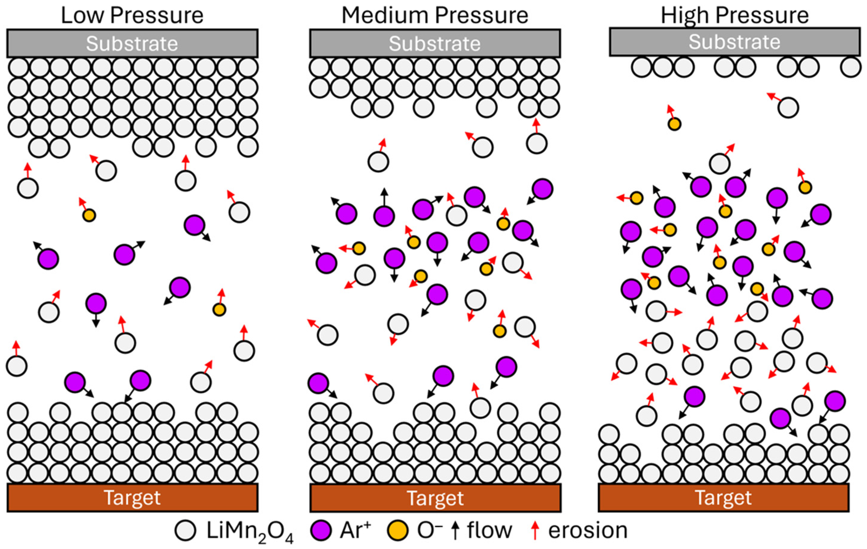
Table 3 presents the coating thickness sizes corresponding to different argon pressures. It has been observed that a higher argon deposition pressure results in coatings with reduced thickness compared to those produced under low argon deposition pressure sputtering conditions. This phenomenon can be explained by Equation (1), which pertains to the mean free path (λ) of target atoms involved in the sputtering deposition [29]. The mean free path is influenced by several factors, including pressure (P), temperature (T), and collision events. Low deposition pressures allow for longer mean free paths for sputtered atoms, as fewer collisions occur with gas molecules in the chamber [29]. This enables the sputtered species to reach the substrate with minimal scattering, causing the formation of a thicker coating in comparison to sputtering conditions with a high deposition pressure [18]. A graphical representation of the described process is depicted in Figure 2.
λ = R T 2 π d 2 N A P
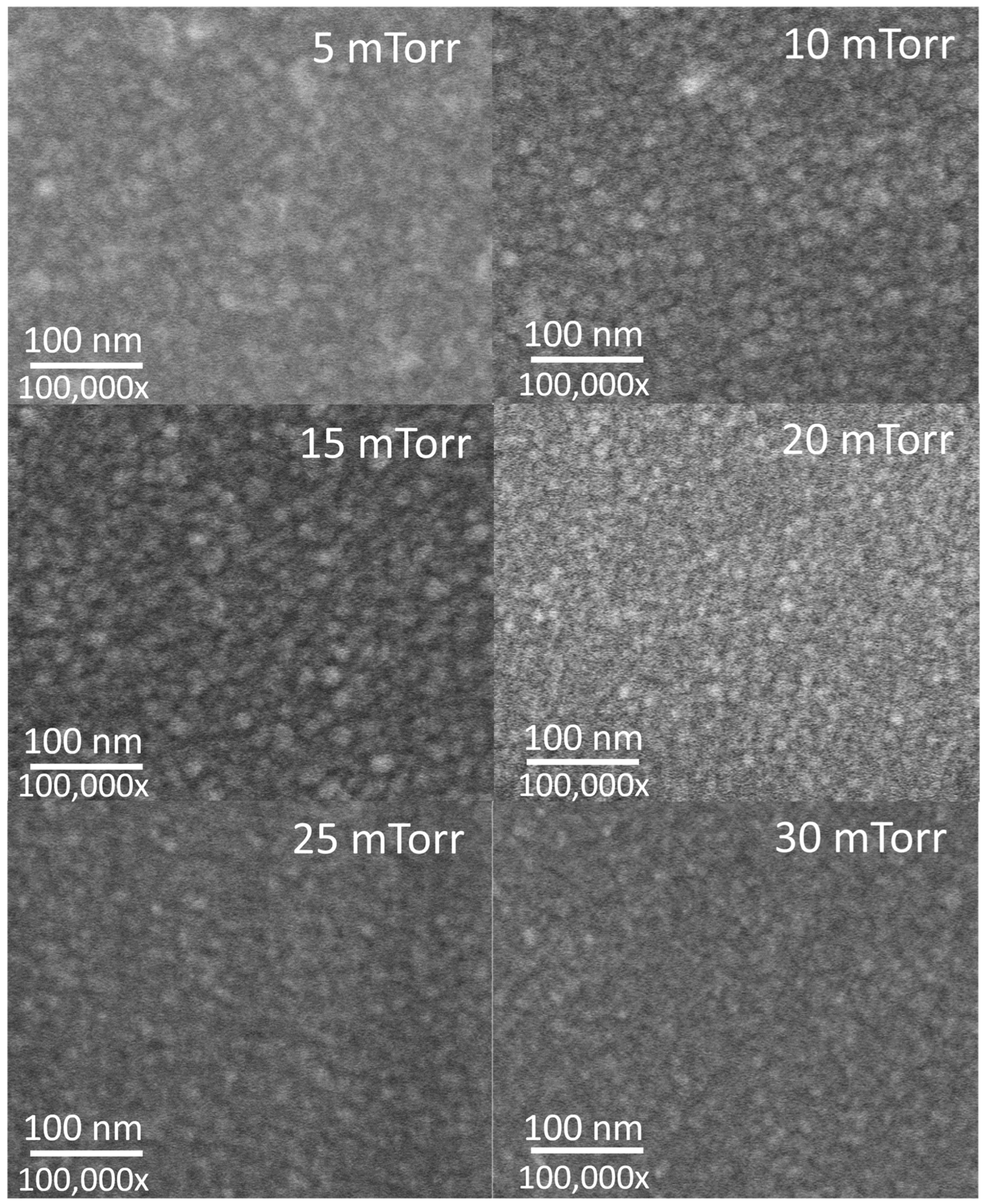
The surface morphology of the coatings was inspected using a scanning electron microscope. As depicted in Figure 3, the annealed coatings exhibit a grain structure indicative of various crystallographic orientations with no defined texture [24]. The grain size was calculated by choosing a small region of each image (250 nm × 250 nm), which was then amplified to manually determine the size. Using ImageJ software, a line was drawn along a particle to determine the diameter. This procedure was replicated 10 times. Two images were considered to obtain the average. Owing to the high kinetic energy of sputtered atoms during sputter deposition, it is common to observe small grain sizes on the surface of annealed coatings [17,29]. In this study, it was observed that films deposited under low, medium, and high argon deposition pressures had average grain sizes of 15 nm, 12 nm, and 9 nm, respectively. This underscores the significant influence of argon deposition pressure on determining the grain size of the films. As argon deposition pressure increases, there is a corresponding decrease in grain size. This phenomenon can be attributed to the longer mean free path of sputtered particles at lower sputtering pressures, enabling them to travel greater distances before encountering gas molecules or other particles in the deposition chamber [29,30]. Consequently, this facilitates the growth of larger grains in the thin film. Conversely, higher sputtering pressures increase the likelihood of collisions between sputtered particles and gas molecules, leading to a more diffuse deposition affecting the grain structure, resulting in smaller grains [29,30].
In energy storage applications, cathode thin films with thicknesses below 100 nm are desired for the fabrication of microbatteries to power microelectromechanical systems, microchips, sensors, etc., because of their large surface area and fast ion/electron transport [31,32].
In addition, the utilization of cathode materials with a fine-grained structure is preferred, as this offers two primary advantages. Firstly, it increases the surface area, thereby providing more active sites for lithium-ion insertion and extraction during battery operation. Secondly, shorter diffusion paths facilitate faster lithium-ion transport, thereby enabling quicker charge and discharge processes [33].

3.2. Chemical Properties

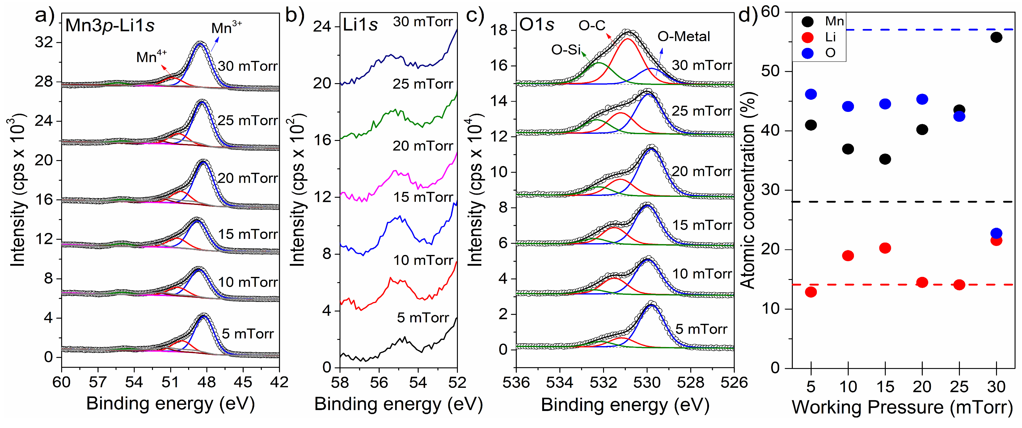
X-ray photoelectron spectroscopy (XPS) was utilized to examine the surface of the sputtered coatings and determine their elemental composition. Figure S3 displays the survey scans for each of the coatings produced under the six different conditions outlined in Table 2. The survey scans, ranging from 1390 to 0 eV, uncovered the presence of manganese, lithium, and oxygen, the chemical elements related to the LiMn2O4 compound. Additionally, Si2p signals were observed, attributed to the substrate. High-resolution scans (Figure 4) were conducted within the chosen binding energy ranges for Mn3p, Li1s, and O1s to establish the elemental composition and oxidation states of the as-deposited coatings.
In Figure 4a, it is evident that two peaks appear at 48.4 and 50.4 eV, corresponding to the two oxidation states of manganese, Mn3+ and Mn4+, respectively. According to Table S1, the concentration ratio between these signals is dependent on the sputtering deposition pressure. Specifically, it has been observed that the peak area associated with Mn3+ signals increases, while the Mn4+ peak area decreases with increasing deposition pressure. This trend suggests a reduction in Mn4+ to Mn3+ during the sputtering deposition process. High argon deposition pressures can result in a higher electron density in the plasma, causing Mn4+ ions to gain electrons and transition to Mn3+ during transport from the target surface to the substrate surface [29,34]. In the LiMn2O4 spinel phase, the desired ratio of Mn4+ to Mn3+ is typically 1:1. According to Table S1, the deposited coatings have a Mn4+/Mn3+ ratio of around 0.3, indicating a significantly higher proportion of Mn3+ compared to Mn4+. The Mn3+ ions are prone to Jahn–Teller distortion due to the asymmetric electron configuration in the d-orbitals. This distortion causes the octahedral symmetry around Mn3+ to be elongated, leading to a local distortion of the spinel structure. A high concentration of Mn3+ will result in more extensive distortions, weakening the crystal structure and causing instability during lithium intercalation and deintercalation [35].
In lithium-ion battery applications, both Mn3+ and Mn4+ oxidation states play significant roles. Mn3+ is involved in the reduction reaction during discharge in a lithium-ion battery [36], contributing to the Mn3+/Mn2+ redox couple that enhances the cathode material’s capacity [37]. Conversely, Mn4+ is typically present in the charged state of LiMn2O4 and undergoes oxidation to Mn3+ during charging [36]. The Mn4+/Mn3+ redox couple is part of the charging process. However, LiMn2O4 with a balanced distribution of Mn3+ and Mn4+ is preferred for its stability and reduced susceptibility to structural degradation during cycling [36,37]. Therefore, a low argon deposition pressure appears to be ideal for producing LiMn2O4 coatings with a more balanced distribution of Mn3+ and Mn4+.
The peak at 54.8 eV in Figure 4b can be ascribed to the principal peak of Li1s atoms in the lattice of LiMn2O4 film. The quantification of elements was carried out using the high-resolution spectra for each of the samples. The quantification contemplated the relative sensitivity factors of Mn3p (0.22), O1s (0.711), and Li1s (0.025). As shown in Table 4 and Figure 4d, every as-deposited coating has its unique chemical concentration. The samples deposited at an argon deposition pressure of 10 and 15 mTorr have a Mn/Li ratio of 1.94 and 1.74, respectively, which are closer to the Mn/Li ratio of the stoichiometric LiMn2O4 compound. Therefore, an argon deposition pressure in the range of 10 to 15 mTorr is the ideal condition for producing stoichiometric LiMn2O4 cathode materials.
As depicted in Figure 4c, the O1s spectrum exhibits three distinct signals corresponding to different components: the silicon substrate (O-Si at 532.4 eV), carbon adsorbate (O-C at 531.4 eV), and the as-deposited coating (O-metal at 529.9 eV). Variations in the peak area of these signals among the six different coatings suggest differences in elemental concentrations across the sputtered coatings. Notably, the signal associated with the coating (O-metal) decreases with an increasing argon deposition pressure, whereas the signal linked to the substrate shows an opposite trend, increasing with a higher argon deposition pressure. This observed phenomenon may be attributed to changes in coating thickness. Specifically, a lower argon deposition pressure yields thicker as-deposited coatings, leading to a diminished O-Si substrate signal and an increased O-metal signal. Conversely, a high argon deposition pressure results in as-deposited films with small thicknesses, resulting in a higher O-Si substrate signal and a lower O-metal signal. This trend aligns with the findings presented in Table 3.
According to the findings in Table 4, a relationship exists between the argon deposition pressure and the coating stoichiometry. The as-deposited coatings display a tendency for reduced oxygen content as the argon deposition pressure rises. This phenomenon can be explained by two key factors. Firstly, the cathode films are generated through a non-reactive deposition approach, which implies bombarding the LiMn2O4 target material with high-energy inert argon cations and a non-reactive gas injection [17]. As a result, oxygen atoms in the growing film solely originate from the LiMn2O4 target material. Secondly, an increase in argon deposition pressure causes an elevation in electron density in the plasma. During transportation from the target source material to the substrate surface, some oxygen atoms react with the argon plasma and obtain an electron, forming negative oxygen ions [38]. These negative oxygen ions do not influence film growth but instead cause film re-sputtering, leading to cathode films with an oxygen deficiency [39]. Based on the lack of oxygen in the sputtered coatings, it can be inferred that negative species were present through the sputtering process. This observation indicates that the deposition process that generated coatings with an elevated oxygen deficiency likely involved a substantial concentration of negative oxygen ions.
Table 4 displays two trends in the cathode coating stoichiometry for the films produced at a small argon deposition pressure range (5 to 15 mTorr). These trends are a rise in lithium content and a decrease in manganese content as the argon deposition pressure increases. However, the sputtering yield values of Table S2 (for a 0° incidence of Ar+), which are 0.42 and 0.67 for Li and Mn, respectively, suggest the opposite. Within the same range of argon deposition pressure, it is expected to observe an increase in manganese and a decrease in lithium content. This discrepancy could be explained by considering the presence of re-sputtering effects through the cathode film deposition processes. As shown in Table S3, lithium and manganese sputtering yields are 0.37 and 0.62, respectively (for 0° incidences of O). Considering this, it can be inferred that in the low argon deposition pressure range, the negative oxygen atoms influence the growing LiMn2O4 film, removing more manganese atoms than lithium atoms. Therefore, the decrease in manganese content as the argon deposition process increases from 5 to 15 mTorr could be related to an increase in the re-sputtering process. At the same time, the increase in lithium content could be associated with its lower sputtering yield.
Table 4 shows two trends in the coating stoichiometry for a large range of argon deposition pressures (20 to 30 mTorr). As the argon deposition pressure increases, there is an increase in manganese content and a decrease in lithium concentration. Interestingly, this trend is opposite to that observed for the coatings produced within the small range of argon deposition pressures (5 to 15 mTorr). The change in trend could be due to a reduction in the re-sputtering effect within this argon deposition range (20 to 30 mTorr). Table S4 shows that a rise in argon deposition pressure leads to an improvement in species concentration inside the sputtering chamber. This increase in concentration augments collisions among the ejected target atoms, plasma species, and negative oxygen species [38,39]. As the collisions involving negative oxygen ions increase, their speed decreases, and their energy reduces [29]. Therefore, at a high argon deposition pressure range (20 to 30 mTorr), the increase in the collision of the sputtering species leads to a reduction in the energy of negative oxygen atoms, which in consequence leads to a minimization of the re-sputtering from the film/substrate surface [38,39]. Consequently, the minimization of the re-sputtering effect and the larger sputtering yield of Mn compared to Li leads to the observed trend of increasing Mn content and decreasing Li content as the argon deposition pressure increases.
According to the X-ray photoelectron spectroscopy study, stoichiometric LiMn2O4 cathode coating materials can be deposited at an argon deposition pressure range in the order of 10 to 15 mTorr. Similarly, an argon deposition pressure of 20, 25, and 30 mTorr caused the creation of non-stoichiometric LiMn2O4 cathode material with a Li deficiency.

3.3. Crystalline Structure Properties

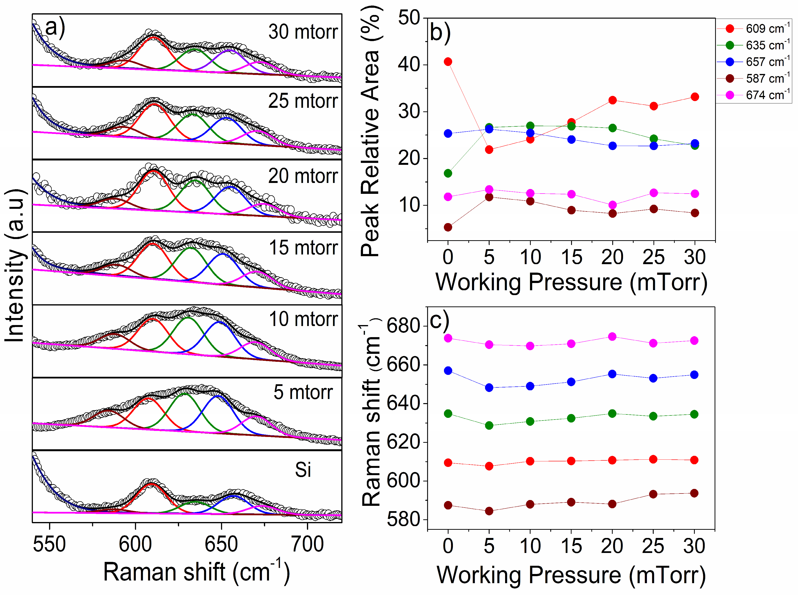
The Raman spectra of annealed LiMn2O4 thin films, deposited at varying working pressures, are illustrated in Figure 5. The spectra exhibit attenuation due to silicon vibrational modes, primarily the one situated at 512 cm−1, as depicted in Figure S4. The reduction in substrate signal contribution at lower working pressures correlates with the thickness of the coating. Figure 5a presents spectra within the 545–710 cm−1 region, chosen due to the noticeable increase compared to the substrate signal. Although silicon contributes to this region, the peaks at 587 and 635 cm−1 exhibit lower area concentrations compared to those corresponding to the LiMn2O4 thin films, indicating their association with this material. The characteristic vibration modes for spinel oxides and manganese oxide materials typically appear within the range of 600–650 cm−1, reflecting the vibration of oxygen atoms within the MnO6 octahedra [40,41]. The principal peak at 635 cm−1 agrees to the symmetric Mn-O stretch vibration A1g-mode. In contrast, the peaks around 587 cm−1 and 647 cm−1 are correlated with the stretch vibration F2g-mode, representing the large oxygen and small manganese atom vibrations, respectively [42,43,44].
To differentiate the coating signal from the substrate signal and confirm the presence of the LiMn2O4 material, peak areas were calculated for each sample at varying working pressures (Figure 4). The primary substrate peak, located at 609 cm−1, diminishes when covered by the LiMn2O4 coating. This decrease is subsequently reversed with an increase in working pressure, attributed to the thicker coating size. Conversely, the peak areas of the coating-related peaks at 587 cm−1 and 635 cm−1 are lower in the substrate, but they increase in the 5 mTorr film, indicating the contribution of the LiMn2O4 material to the signal. Furthermore, Figure 5c illustrates the Raman shift with respect to different working pressures. A slight shift toward higher wavelengths is observed in the 5 to 15 mTorr samples, potentially linked to an increase in Mn4+ concentration (as per Table 3). Conversely, the Mn4+ concentration is lower for the 20 to 30 mTorr samples, suggesting a shift toward lower wavelengths.
The development of the LiMn2O4 crystalline phase, as implied by the Raman spectroscopy analysis, was validated by performing an X-ray diffraction analysis on the six samples deposited at different argon deposition pressures. The X-ray diffraction patterns from each sputtered film are shown in Figure S5. The identified diffraction planes were designated to the LiMn2O4 phase, the silicon substrate, and the X-ray diffractometer instrument. The analysis revealed that thermal annealing for one hour resulted in the crystallization of the as-sputtered LiMn2O4 films.

3.4. Electrochemical Performance

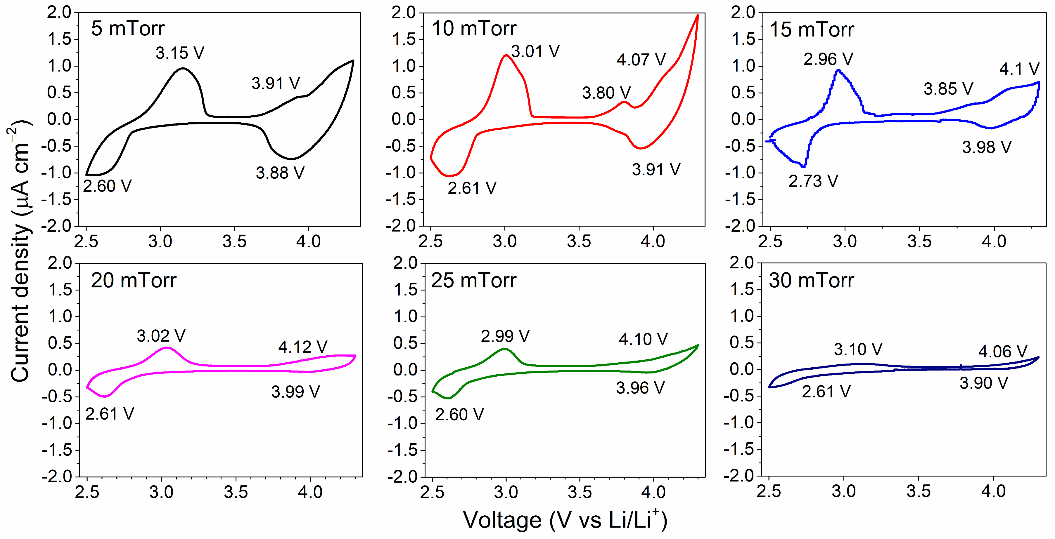
After the deposition of cathode coatings, the samples underwent thermal annealing at 500 °C for one hour under laboratory ambient conditions. Subsequently, these heat-treated films were assessed as cathodes in coin cells, with a lithium foil acting as the counter electrode. Cyclic voltammograms, shown in Figure 6, were recorded within a potential range of 2.5 to 4.3 V vs. Li/Li+ at a scan rate of 0.05 mV per second.
In Figure 6, the cyclic voltammogram for the stoichiometric LiMn2O4 cathode material deposited at 10 mTorr reveals two distinct regions of electrochemical activity. In the high-voltage range (3.7 to 4.3 V vs. Li/Li+), the oxidation peak of LiMn2O4 appears at 4.07 V, indicating the deintercalation of lithium from the structure and the oxidation of manganese ions in the lattice from Mn3+ to Mn4+ [36]. The reduction peak of LiMn2O4 at 3.91 V vs. Li/Li+ represents the insertion of lithium into the lattice and the reduction of manganese ions from Mn4+ back to Mn3+ [36]. In the low-voltage regime (2.5 to 3.1 V vs. Li/Li+), the observed redox couple at 3.01 V (oxidation peak) and 2.61 V (reduction peak) are linked to a Jahn–Teller distortion [45]. Additionally, the appearance of this redox couple is accompanied by the formation of an oxidation peak at 3.80 V [36]. The cyclic voltammogram obtained from the stoichiometric cathode material LiMn2O4 closely resembles the results reported by the research group of J. M. Tarascon et al. [36].
Several observations were made regarding the non-stoichiometric LiMn2O4 coatings. Firstly, an increase in argon deposition pressure resulted in a reduction in the current density recorded in the cyclic voltammogram, indicating reduced electrochemical activity. Secondly, the cyclic voltammograms of non-stoichiometric LiMn2O4 coatings deposited at 20, 25, and 30 mTorr exhibited attenuated pairs of oxidation-reduction voltage peaks in the high -voltage regime (3.7 to 4.2 V vs. Li/Li+), suggesting weakened discharge and charge processes. Equations (2) and (3) demonstrate that the charge/discharge reactions in the LiMn2O4 phase involve electrical charges, and the decrease in current density implies the impairment of both chemical reactions [46]. Thirdly, the cyclic voltammograms of non-stoichiometric LiMn2O4 samples produced at 30 mTorr showed no reduction peaks in the low-voltage range of 2.5 to 3.2 V vs. Li/Li+, indicating the disabling of Jahn–Teller distortion [45,47].
Discharge: LiMn2O4 →Li2Mn2O4 + 2Li+ + 2e
Charge: Li2Mn2O4 + 2Li+ + 2e →LiMn2O4
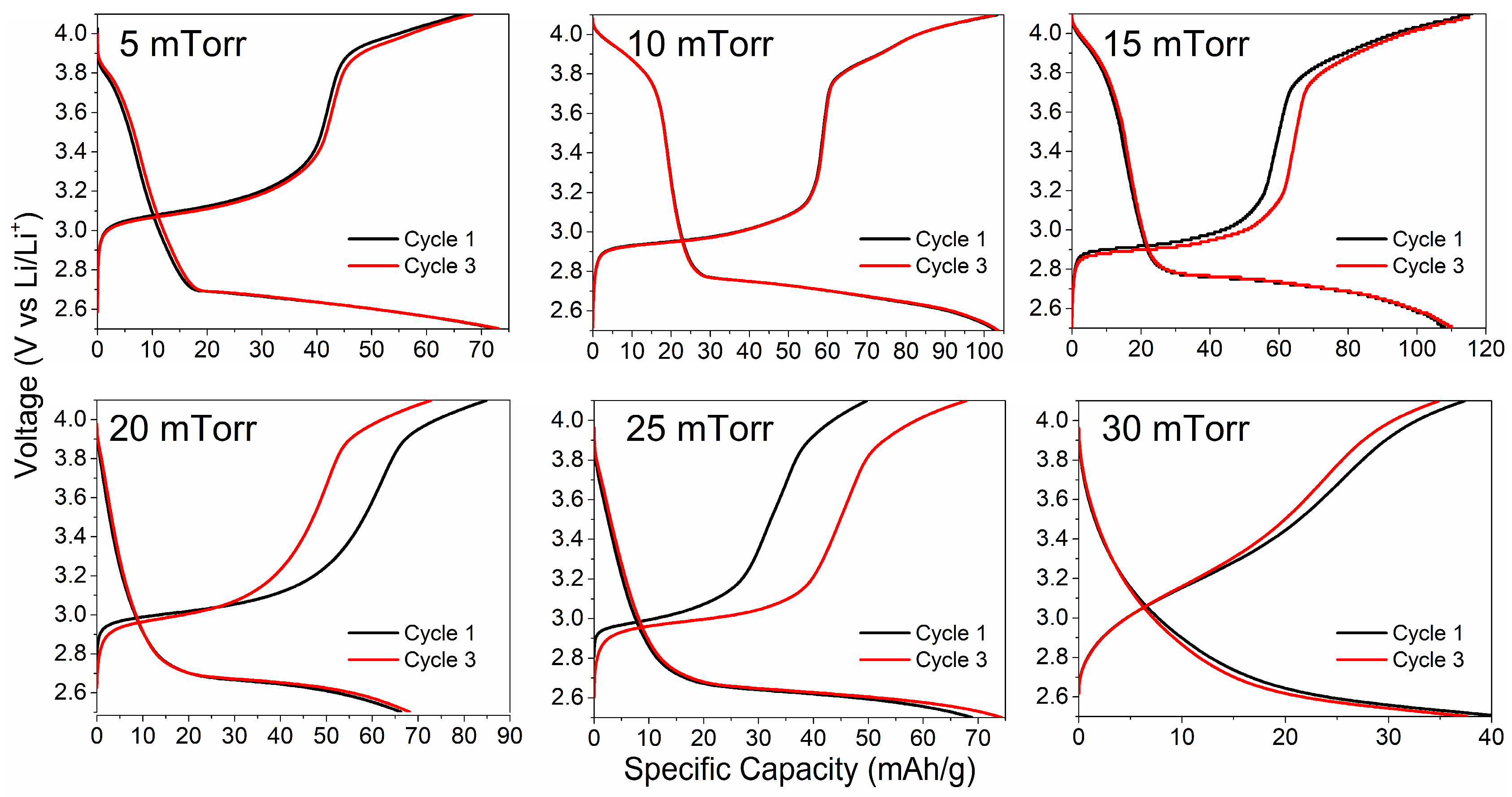
Figure 7 displays the initial charge–discharge curves of the LiMn2O4 cathode films arranged at different deposition pressures of argon (ranging from 5 to 30 mTorr). Complete cells were cycled between 2.5 and 4.3 V at a fixed current of one microampere. The stoichiometric LiMn2O4 coatings, produced at 10 and 15 mTorr, exhibit distinct voltage plateaus. The charging curve reveals plateaus at various voltages, including 2.9 V, 3.8 V, and 3.9 V, while the discharge curve presents the onset of the plateau at a voltage of 3.8 V. These plateaus correspond to electrochemical reactions occurring within the LiMn2O4 cathode material [36].
The similar discharge capacities observed between the first and third cycle indicate a good cycling stability with a minimal capacity fade, a typical characteristic of the LiMn2O4 phase. However, this amount is lower than both the theoretical capacity of spinel LiMn2O4 (148 mAh/g) and the experimental values reported in the literature (124 mAh/g) [48,49]. The lower capacity registered for the stoichiometric LiMn2O4 cathode material could be attributed to factors such as inefficiencies, side reactions, and the absence of conductive agents during the coating deposition process [20].
LiMn2O4 cathode materials with a lithium deficiency, deposited at 20, 25, and 30 mTorr, exhibit a moderate initial discharge capacity varying between 40 mAh/g (30 mTorr) and 68 mAh/g (20 mTorr). However, there is a significant variation in the discharge capacity between the first and third cycles, indicating that these materials may not be suitable for extended charge–discharge cycles [48]. This discrepancy could stem from the low stability of their crystal structure due to the absence of lithium atoms in the stoichiometric composition, as suggested by the XPS studies (Table 4).
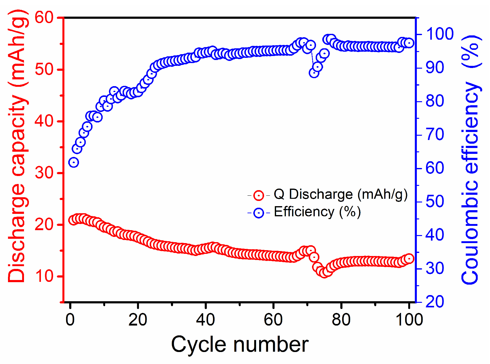
The capacity retention behavior of the stoichiometric LiMn2O4 cathode film is illustrated in Figure 8. The charge–discharge curves were recorded within a voltage range of 2.5 to 4.1 V at a current rate of 13 μAmp at room temperature (Figure S6). As shown in Figure 8, the Coulombic efficiency of the first cycle, determined by the specific discharge and charge capacities in a single charge/discharge cycle, is 32%. As the number of cycles increases, there is an observed rise in Coulombic efficiency within the range of 90 to 100%. The low Coulombic efficiency in the early cycles can be attributed to structural changes in the LiMn2O4 spinel due to Jahn–Teller distortions and initial lithium inventory losses [50]. Once these processes stabilize, the stoichiometric LiMn2O4 cathode film achieves a higher and more stable Coulombic efficiency. However, during the cycling test, the stoichiometric LiMn2O4 cathode film experiences significant capacity fading. The discharge capacity drops from 20 to 13 mAh/g, resulting in a capacity retention of just 65% after 100 cycles. This low retention could be attributed to the small cathode thickness, where the high surface-to-volume ratio leads to a faster degradation, limiting the cycle life of the battery [51].
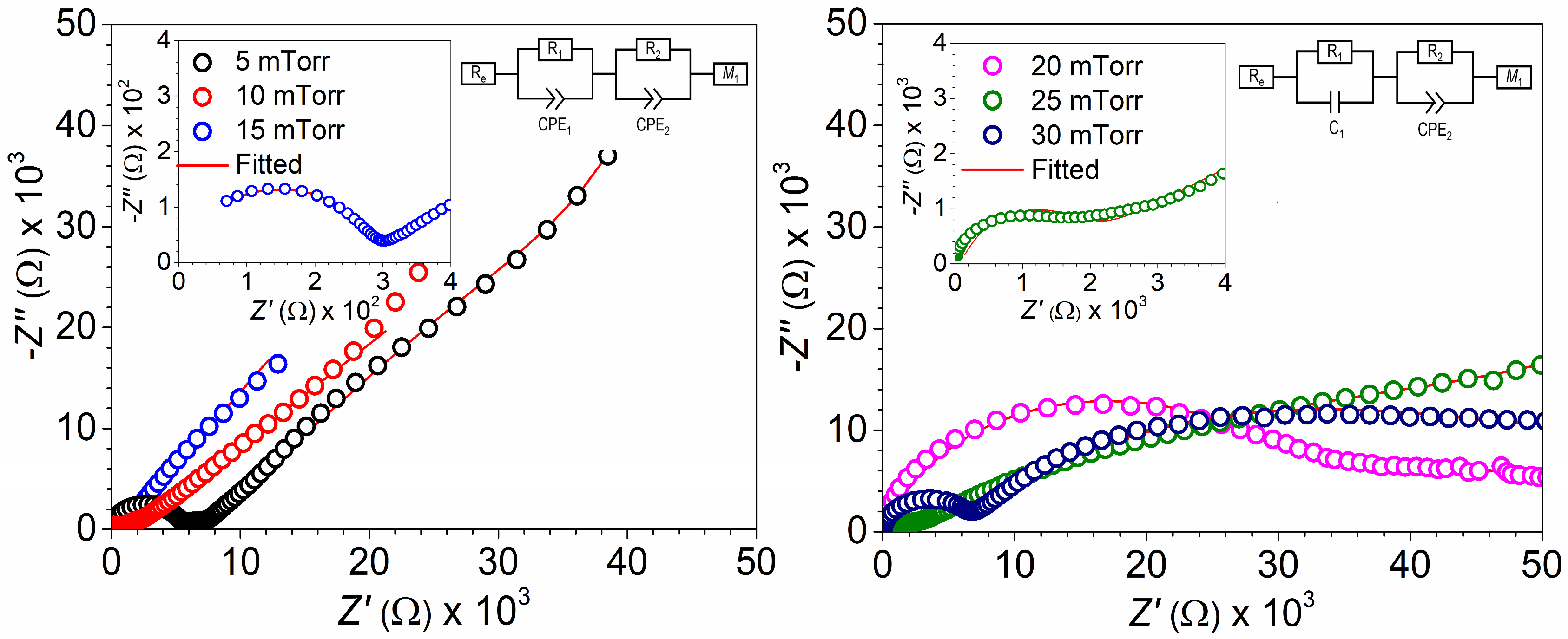
Electrochemical impedance spectroscopy experiments were conducted on LiMn2O4 coatings with stoichiometric and non-stoichiometric compositions to gather additional information about their electrochemical performance. Figure 9 illustrates the Nyquist plots obtained from two different cell configurations: low- and high-pressure argon deposition cathode-material-based cells. The Nyquist plots obtained from the experiment were analyzed by employing equivalent circuits (shown in the figure insets) to analyze both physical and electrochemical behaviors; the calculated values are presented in Table 5. The high-frequency region of the Nyquist plot offers insights into the electrical resistance of the electrolyte solution (Re). As shown in Table 5, the average electrical resistance of the LiPF6 liquid electrolyte used in each of the six different cell batteries remains around 4.5 ohms. The recorded low resistance indicates higher ionic conductivity, a desirable characteristic for the electrolyte to facilitate the movement of lithium ions between the cathode and anode during the battery’s charging and discharging processes [52].
The mid-high-frequency region provides important information related to the charge transfer process, the constant phase element at the electrode–passivation layer interface, and the charge transfer process at the cathode surface. The stoichiometric LiMn2O4 coating produced at 15 mTorr exhibits the lowest charge transfer process at both the electrolyte/electrode interface (R1 = 271 Ω) and the surface material (R2 = 619 Ω) in comparison to the non-stoichiometric LiMn2O4 cathode materials. A low charge transfer rate implies that the stoichiometric LiMn2O4 sample facilitates the movement of lithium ions in and out of the cathode material’s crystal lattice, resulting in a high capacity (116 mAh/g) [19,20,21]. Simultaneously, the low charge capacity (40 mAh/g) observed in the non-stoichiometric LiMn2O4 sample produced at 30 mTorr could be associated with its high electrical resistance at the electrode/electrolyte interface (R1 = 5236 Ω) and surface (R1 = 48,529 Ω). This is consistent and correlates with the electrical resistivity values determined by the four-point method.
At lower frequencies, the linear portion of the data provides information about the diffusion coefficient of the intercalated species. To determine the lithium-ion diffusion coefficient (DLi+), the real part resistance is plotted against the inverse square root of the angular frequency within the low-frequency range. The slope of this plot is utilized to derive the Warburg factor (σ), and the following equation is applied to estimate DLi+:
D L i + = R 2 T 2 2 A 2 n 4 F 4 C 2 σ 2
where T is the temperature (298 K), R is the gas constant (8.314 J/molK), A is the surface area of the LiMn2O4 sample, n is the number of transferred electrons, F is the Faraday constant (96,500 C/mol), C is the Li+ concentration (mol/L, in the electrolyte), and σ is the Warburg coefficient, which is related to Z′ (slope of the fitted Z′/σ1/2 line) [53].
Table 5 indicates that cathode coatings produced at a low argon deposition pressure had a higher lithium diffusion coefficient (DLi+ = 5.19 × 10⁻¹² cm2/s) compared to those produced at a high argon deposition pressure (DLi+ = 1.34 × 10⁻¹⁴ cm2/s). In energy storage applications, a high lithium diffusion coefficient is desirable as it increases lithium ions’ diffusion through the cathode material [20]. The faster lithium diffusion coefficient of the non-stoichiometric LiMn2O4 cathode material (DLi+ = 5.19 × 10⁻¹² cm2/s compared to the stoichiometric LiMn2O4 cathode material (DLi+ = 3.22 × 10⁻¹² cm2/s) suggests that the electrochemical performance of the cathode material depends on crucial parameters, such as charge transfer at the electrolyte/electrode interface and the surface, rather than solely on the lithium diffusion coefficient. It is complicated to see a trend in diffusion coefficient because it depends on different factors and not only on the three resistances that were obtained by the Nyquist plot. It is suggested that the samples deposited at 10 mTorr show the highest diffusion coefficient, which could be attributed mainly to chemical composition and crystalline properties. As was discussed earlier, this sample is the one that is close to the stoichiometric compound.

4. Conclusions

The current research highlights the significant effect of controlling the argon pressure on the chemical properties of the LiMn2O4 cathode and, consequently, on the electrochemical performance of solid-state batteries. It has been noted that the peak area associated with Mn3+ signals increases while the peak area of Mn4+ decreases with rising deposition pressure. Elevated argon deposition pressures may lead to a greater electron density in the plasma, facilitating the transfer of electrons from Mn4+ ions, causing them to transition to Mn3+ while traversing from the target surface to the substrate surface.
Variation in the deposition parameter leads to the formation of two groups of coating chemistries:
  • Group I (stoichiometric LiMn2O4 cathode materials): This group was obtained in the argon deposition range from 5 to 15 mTorr, where an argon deposition pressure of 15 mTorr leads to the growth of a 30 nm thick LiMn2O4 cathode material which exhibits low charge transfer at both the electrolyte/electrode interface (R1 = 271 Ω) and the surface (R2 = 619 Ω), alongside high lithium-ion diffusion (DLi+ = 2.19 × 10⁻¹³ cm2/s), facilitating a high discharge capacity of 116 mAh/g.
  • Group II (non-stoichiometric LiMn2O4 cathode materials with lithium deficiency): This group was obtained in the argon deposition range from 20 to 30 mTorr. The deposition of LiMn2O4 cathode materials with lithium deficiency at the lower end of the range (30 mTorr) resulted in a 30 nm thick cathode material with an unbalanced Mn4+/Mn3+ ratio of 0.2. This led to a decrease in the oxidation/reduction peaks in cyclic voltammograms at of high-voltage regime (3.7 to 4.1 V vs. Li/Li+) and a reduction in the plateau region in the charge/discharge curve, ultimately resulting in a moderate discharge capacity of 40 mAh/g.

Supplementary Materials

The following supporting information can be downloaded at: https://www.mdpi.com/article/10.3390/batteries10120449/s1: Experimental details in the electrical characterization, surface and cross-section micrograph images, XPS surveys, Raman spectra (full-range), XRD patterns, and electrical properties of the different LiMn2O4 samples are presented for further information. A fatigue test for the 15 mTorr sample was performed. The specific parameters of the sputtering deposition process obtained by STRIM software are reported. References [54,55,56,57,58,59,60,61,62,63,64] are cited in the Supplementary Materials.

Author Contributions

F.A.-V.: conceptualization, data curation, formal analysis, investigation, methodology, software, supervision, visualization, writing—original draft; R.G.-H.: conceptualization, data curation, formal analysis, investigation, methodology, project administration, supervision, validation, writing—review and editing, funding acquisition; J.S.M.-F.: data curation, formal analysis, investigation, methodology; F.S.A.-T.: formal analysis, methodology, investigation, validation, writing—review and editing; E.M.-G.: formal analysis, investigation, validation, writing—review and editing; M.Q.-L.: investigation, validation, writing—review and editing. All authors have read and agreed to the published version of the manuscript.

Funding

This research was funded by Consejo Nacional de Humanidades, Ciencia y Tecnología from Mexico (CONAHCYT) through grant CBF2023-2024-3089.

Data Availability Statement

The data presented in this study are available on request.

Acknowledgments

The authors thank Christian Albor Cortes and Maria Isabel Mendivil Palma for their technical support on the SEM measurements and aluminum-contact deposition, respectively. Additionally, the authors would like to thank Andreas Ruediger for his help with the Raman measurements. The authors acknowledge Laboratorio Nacional CONAHCYT en Microtecnología y BioMEMS (LaNMiB) for the facilities provided to carry out the cathode deposition experiments.

Conflicts of Interest

The authors declare no conflicts of interest.

References

  1. Rambabu, A.; Krupanidhi, S.B.; Barpanda, P. An overview of nanostructured Li-based thin film micro-batteries. Proc. Indian Natl. Sci. Acad. 2019, 85, 121–142. [Google Scholar] [CrossRef]
  2. Yu, Y.; Gong, M.; Dong, C.; Xu, X. Thin-film deposition techniques in surface and interface engineering of solid-state lithium batteries. Next Nanotechnol. 2023, 3–4, 100028. [Google Scholar] [CrossRef]
  3. Zhou, Y.N.; Xue, M.Z.; Fu, Z.W. Nanostructured thin film electrodes for lithium storage and all-solid-state thin-film lithium batteries. J. Power Sources 2013, 23, 310–332. [Google Scholar] [CrossRef]
  4. Moitzheim, S.; Put, B.; Vereecken, P.M. Advances in 3D thin-film Li-ion batteries. Adv. Mater. Interfaces 2019, 6, 1900805. [Google Scholar] [CrossRef]
  5. Sun, K.; Wei, T.S.; Ahn, B.Y.; Seo, J.Y.; Dillon, S.J.; Lewis, J.A. 3D printing of interdigitated Li-ion microbattery architectures. Adv. Mater. 2013, 25, 4539–4543. [Google Scholar] [CrossRef]
  6. Wang, Y.; Liu, B.; Li, Q.; Cartmell, S.; Ferrara, S.; Deng, Z.D.; Xiao, J. Lithium and lithium-ion batteries for applications in microelectronic devices: A review. J. Power Sources 2015, 286, 330–345. [Google Scholar] [CrossRef]
  7. Liu, L.; Weng, Q.; Lu, X.; Sun, X.; Zhang, L.; Schmidt, O.G. Advances on Microsized On-Chip Lithium-Ion Batteries. Small 2017, 13, 1701847. [Google Scholar] [CrossRef]
  8. Wu, T.; Dai, W.; Ke, M.; Huang, Q.; Lu, L. All-Solid-State Thin Film μ-Batteries for Microelectronics. Adv. Sci. 2021, 8, 2100774. [Google Scholar] [CrossRef] [PubMed]
  9. Meunier, G.; Dormoy, R.; Levasseur, A. New Positive Electrode Materials for Lithium Thin Film Secondary Batteries. Mater. Sci. Eng. B 1989, 83, 19–23. [Google Scholar] [CrossRef]
  10. Jones, S.D.; Akridge, J.R. A thin-film solid-state microbattery. J. Power Sources 1993, 43-44, 505–551. [Google Scholar] [CrossRef]
  11. Fu, W.; Wang, Y.; Kong, K.; Kim, D.; Wang, F.; Yushin, G. Materials and Processing of Lithium-Ion Battery Cathodes. Nanoenergy Adv. 2023, 3, 138–154. [Google Scholar] [CrossRef]
  12. Chakraborty, A.; Kunnikuruvan, S.; Kumar, S.; Markovsky, B.; Aurbach, D.; Dixit, M.; Major, D.T. Layered Cathode Materials for Lithium-Ion Batteries: Review of Computational Studies on LiNi1−x−yCoxMnyO2 and LiNi1−x−yCoxAlyO2. Chem. Mater. 2020, 32, 915–952. [Google Scholar] [CrossRef]
  13. Ammundsen, B.; Paulsen, J. Novel Lithium-Ion Cathode Materials Based on Layered Manganese Oxides. Adv. Mater. 2001, 13, 943–956. [Google Scholar] [CrossRef]
  14. Huang, Y.; Dong, Y.; Li, S.; Lee, J.; Wang, C.; Zhu, Z.; Xue, W.; Li, Y.; Li, J. Lithium Manganese Spinel Cathodes for Lithium-Ion Batteries. Adv. Energy Mater. 2020, 11, 2000997. [Google Scholar] [CrossRef]
  15. Thackeray, M.M.; David, W.I.; Bruce, P.G.; Goodenough, J.B. Lithium insertion into manganese spinels. Mater. Res. Bull. 1983, 18, 461. [Google Scholar] [CrossRef]
  16. Thackeray, M.M.; Johnson, P.J.; De Picciotto, L.A.; Bruce, P.G.; Goodenough, J.B. Electrochemical extraction of lithium from LiMn2O4. Mater. Res. Bull. 1984, 19, 179. [Google Scholar] [CrossRef]
  17. Ma, Y.; Li, L.; Qian, J.; Qu, W.; Luo, R.; Wu, F.; Chen, R. Materials and structure engineering by magnetron sputtering for advanced lithium batteries. Energy Storage Mater. 2021, 39, 203–224. [Google Scholar] [CrossRef]
  18. Ugalde-Vázquez, R.M.; Ambriz-Vargas, F.; Morales-Morales, F.; Hernández-Sebastián, N.; Benítez-Lara, A.; Cabrera-Sierra, R.; Gomez-Yañez, C. Effect of argon sputtering pressure on the electrochemical performance of LiFePO4 cathode. J. Eur. Ceram. Soc. 2023, 43, 407–418. [Google Scholar] [CrossRef]
  19. Ye, R.; Ohta, K.; Baba, M. Fabrication and Characterization of LiMn2O4 Thin Films for Flexible Thin Film Lithium ion Batteries: Effect of thermal Annealing. Int. J. Eng. Sci. Technol. 2021, 8, 2394–3661. [Google Scholar] [CrossRef]
  20. Chen, H.C.; Jan, D.J.; Lin, B.C.; Hsueh, T.H. Nanostructure distortion improvement of Al doped spinel LiMn2O4 films deposited by RF magnetron sputtering for flexible high-voltage lithium ion batteries. Mater. Res. Bull. 2021, 140, 111313. [Google Scholar] [CrossRef]
  21. Hsueh, T.H.; Yu, Y.Q.; Jan, D.J.; Su, C.H.; Chang, S.M. Checkerboard deposition of lithium manganese oxide spinel (LiMn2O4) by RF magnetron sputtering on a stainless steel in all-solid-state thin film battery. IOP Conf. Ser. Mater. Sci. Eng. 2018, 324, 012004. [Google Scholar] [CrossRef]
  22. Prasad, K.H.; Vinoth, S.; Ratnakar, A.; Venkateswarlu, M.; Satyanarayana, N. Satyanarayana. Structural and Electrical Conductivity studies of Spinel LiMn2O4 Cathode films grown by RF Sputtering. Mater. Today Proc. 2016, 3, 4046–4051. [Google Scholar] [CrossRef]
  23. Kong, W.Y.; Yim, H.; Yoon, S.J.; Nahm, S.; Choi, J.W. Electrochemical Properties of Sn-Substituted LiMn2O4 Thin Films Prepared by Radio-Frequency Magnetron Sputtering. J. Nanosci. Nanotechnol. 2013, 13, 3288–3292. [Google Scholar] [CrossRef] [PubMed]
  24. Jayanth Babu, K.; Jeevan Kumar, P.; Hussain, O.M. Microstructural and electrochemical properties of rf-sputtered LiMn2O4 thin film cathodes. Appl. Nanosci. 2012, 2, 401–407. [Google Scholar] [CrossRef]
  25. Zhu, J.; Zeng, K.; Lu, L. Cycling effects on surface morphology, nanomechanical and interfacial reliability of LiMn2O4 cathode in thin film lithium ion batteries. Electrochim. Acta. 2012, 68, 52–59. [Google Scholar] [CrossRef]
  26. Isai, M.; Nakamura, K.; Hosokawa, T.; Sakai, S.; Hosoe, S. Preparation of LiMn2O4 Films by RF Magnetron Sputtering Method. Trans. Mat. Res. Soc. Jpn. 2009, 34, 355–358. [Google Scholar] [CrossRef]
  27. Hwang, B.J.; Wang, C.Y.; Cheng, M.Y.; Santhanam, R. Structure, Morphology, and Electrochemical Investigation of LiMn2O4 Thin Film Cathodes Deposited by Radio Frequency Sputtering for Lithium Microbatteries. J. Phys. Chem. C 2009, 113, 11373–11380. [Google Scholar] [CrossRef]
  28. Xie, J.; Tanaka, T.; Imanishi, N.; Matsumura, T.; Hirano, A.; Takeda, Y.; Yamamoto, O. Yamamoto. Li-ion transport kinetics in LiMn2O4 thin films prepared by radio frequency magnetron sputtering. J. Power Sources 2008, 180, 576–581. [Google Scholar] [CrossRef]
  29. Thomann, A.L.; Caillard, A.; Raza, M.; El Mokh, M.; Cormier, P.A.; Konstantinidis, S. Energy flux measurements during magnetron sputter deposition processes. Surf. Coat. Technol. 2019, 377, 124887. [Google Scholar] [CrossRef]
  30. Jameel, D. Thin Film Deposition Processes. J. Mod. Phys. A 2015, 1, 193–199. [Google Scholar]
  31. Julien, C.M.; Mauger, A.; Hussain, O.M. Sputtered LiCoO2 Cathode Materials for All-Solid-State Thin-Film Lithium Microbatteries. Materials 2019, 12, 2687. [Google Scholar] [CrossRef]
  32. Albrecht, D.; Wulfmeier, H.; Fritze, H. Preparation and Characterization of c-LiMn2O4 Thin Filmsprepared by Pulsed Laser Deposition for Lithium-Ion Batteries. Energy Technol. 2016, 4, 1558–1564. [Google Scholar] [CrossRef]
  33. Chen, Z.; Zhang, W.; Yang, Z. A review on cathode materials for advanced lithium ion batteries: Microstructure designs and performance regulations. Nanotechnology 2020, 31, 012001. [Google Scholar] [CrossRef] [PubMed]
  34. Shirazi Moghadam, Y.; El Kharbachi, A.; Diemant, T.; Melinte, G.; Hu, Y.; Fichtner, M. Toward Better Stability and Reversibility of the Mn4+/Mn2+ Double Redox Activity in Disordered Rocksalt Oxyfluoride Cathode Materials. Chem. Mater. 2021, 33, 8235–8247. [Google Scholar] [CrossRef]
  35. Aghilizadeh, N.; Sari, A.H.; Dorranian, D. Role of Ar/O2 mixture on structural, compositional and optical properties of thin copper oxide films deposited by DC magnetron sputtering. Theor. Appl. Phys. 2017, 11, 285–290. [Google Scholar] [CrossRef]
  36. Tarascon, J.M.; Guyomard, D. Li Metal-Free Rechargeable Batteries Based on Lil+xMn2O4 Cathodes ( 0 ≤ x ≤ 1 ) and Carbon Anodes. J. Electrochem. Soc. 1991, 138, 2864–2868. [Google Scholar] [CrossRef]
  37. Lee, J.; Kitchaev, D.A.; Kwon, D.H.; Lee, C.W.; Papp, J.K.; Liu, Y.S.; Lun, Z.; Clément, R.J.; Shi, T.; McCloskey, B.D.; et al. Reversible Mn2+/Mn4+ double redox in lithium-excess cathode materials. Nature 2018, 556, 185–190. [Google Scholar] [CrossRef] [PubMed]
  38. Poolcharuansin, P.; Chingsungnoen, A.; Pasaja, N.; Horprathum, M.; Bradley, J.W. Measurement of negative ion fluxes during DC reactive magnetron sputtering of Ti in Ar/O2 atmosphere using a magnetic-filtering probe. Vacuum 2021, 194, 110549. [Google Scholar] [CrossRef]
  39. Vargas, F.A.; Nouar, R.; Bacar, Z.S.; Higuera, B.; Porter, R.; Sarkissian, A.; Thomas, R.; Ruediger, A. On-axis radio frequency magnetron sputtering of stoichiometric BaTiO3 target: Localized re-sputtering and substrate etching during thin film growth. Thin Solid Film. 2015, 596, 77–82. [Google Scholar] [CrossRef]
  40. Ramana, C.V.; Massot, M.; Julien, C.M. XPS and Raman spectroscopic characterization of LiMn2O4 spinels. Surf. Interface Anal. 2005, 37, 412–416. [Google Scholar] [CrossRef]
  41. Julien, C.M.; Massot, M. Lattice Vibrations of Materials for Lithium Rechargeable Batteries I. Lithium Manganese Oxide Spinel. Mater. Sci. Eng. B 2003, 97, 217–230. [Google Scholar] [CrossRef]
  42. Baddour-Hadjean, R.; Pereira-Ramos, J.P. Microspectrometry Applied to the Study of Electrode Materials for Lithium Batteries. Chem. Rev. 2010, 110, 1278–1319. [Google Scholar] [CrossRef] [PubMed]
  43. Slautin, B.; Alikin, D.; Rosato, D.; Pelegov, D.; Shur, V.; Kholkin, A. Local Study of Lithiation and Degradation Paths in LiMn2O4 Battery Cathodes: Confocal Raman Microscopy Approach. Batteries 2018, 4, 21. [Google Scholar] [CrossRef]
  44. Paolone, A.; Sacchetti, A.; Corridoni, T.; Postorino, P.; Cantelli, R.; Rousse, G.; Masquelier, C. MicroRaman spectroscopy on LiMn2O4: Warnings on laser-induced thermal decomposition. Solid State Ion. 2004, 170, 135–138. [Google Scholar] [CrossRef]
  45. Haruna, A.B.; Barrett, D.H.; Rodella, C.B.; Erasmus, R.M.; Venter, A.M.; Sentsho, Z.N.; Ozoemena, K.I. Microwave irradiation suppresses the Jahn-Teller distortion in Spinel LiMn2O4 cathode material for lithium-ion batteries. Electrochim. Acta 2022, 426, 140786. [Google Scholar] [CrossRef]
  46. Ma, S.; Noguchi, H.; Yoshio, M. Cyclic voltammetric study on stoichiometric spinel LiMn2O4 electrode at elevated temperature. J. Power Sources 2001, 97–98, 385–388. [Google Scholar] [CrossRef]
  47. Knyazev, A.V.; Mączka, M.; Smirnova, N.N.; Knyazeva, S.S.; Chernorukov, N.G.; Ptak, M.; Shushunov, A.N. Study of the phase transition and thermodynamic functions of LiMn2O4. Thermochim. Acta 2014, 593, 58–64. [Google Scholar] [CrossRef]
  48. Radzi, Z.I.; Arifin, K.H.; Kufian, M.Z.; Balakrishnan, V.; Raihan, S.R.S.; Abd Rahim, N.; Subramaniam, R. Review of spinel LiMn2O4 cathode materials under high cut-off voltage in lithium-ion batteries: Challenges and strategies. J. Electroanal. Chem. 2022, 920, 116623. [Google Scholar] [CrossRef]
  49. Kim, S.; Kumar, V.; Seo, D.; Park, Y.; Kim, J.; Kim, H.; Kim, J.; Hong, J.; Kang, K. Invited Paper: Preparation and Electrochemical Characterization of Doped Spinel LiMn1.88Ge0.1Li0.02O4 Cathode Material. Electron. Mater. Lett. 2011, 7, 105–108. [Google Scholar] [CrossRef]
  50. Yu, X.; Qian, K.; Du, L.; Zhang, J.; Lu, N.; Miao, Z.; Li, Y.; Kobayashi, H.; Yan, X.; Li, R. A strong Jahn–Teller distortion in Mn3O4–MnO heterointerfaces for enhanced silver catalyzed formaldehyde reforming into hydrogen. Sustain. Energy Fuels 2022, 6, 3068–3077. [Google Scholar] [CrossRef]
  51. Labyedh, N.; Mattelaer, F.; Detavernier, C.; Vereecken, P.M. 3D LiMn2O4 thin-film electrodes for high rate all solid-state lithium and Li-ion microbatteries. J. Mater. Chem. A 2019, 7, 18996–19007. [Google Scholar] [CrossRef]
  52. Schweikert, N.; Hahn, H.; Indris, S. Cycling behaviour of Li/Li4Ti5O12 cells studied by electrochemical impedance spectroscopy. Phys. Chem. Chem. Phys. 2011, 13, 6234–6240. [Google Scholar] [CrossRef] [PubMed]
  53. Huger, E.; Uxa, D.; Schmidt, H. Electrochemical (PITT, EIS) and Analytical (SIMS) Determination of Li Diffusivities at the Onset of Charging LiNi0.33Mn0.33Co0.33O2. Electrodes. J. Phys. Chem. C 2024, 128, 7408–7423. [Google Scholar] [CrossRef]
  54. Berg, H.; Thomas, J.O. Neutron diffraction study of electrochemically delithiated LiMn2O4 spinel. Solid State Ion. 1999, 123, 227–234. [Google Scholar] [CrossRef]
  55. Lee, H.W.; Muralidharan, P.; Ruffo, R.; Mari, C.M.; Cui, Y.; Kim do, K. Ultrathin Spinel LiMn2O4 Nanowires as High Power Cathode Materials for Li-Ion Batteries. Nano Lett. 2010, 10, 3852–3856. [Google Scholar] [CrossRef] [PubMed]
  56. Kiani, M.A.; Mousavi, M.F.; Rahmanifar, M.S. Synthesis of Nano- and Micro-Particles of LiMn2O4: Electrochemical Investigation and Assessment as a Cathode in Li Battery. Int. J. Electrochem. Sci. 2011, 6, 2581–2595. [Google Scholar] [CrossRef]
  57. Tang, W.; Liu, L.L.; Tian, S.; Li, L.; Li, L.L.; Yue, Y.B.; Bai, Y.; Wu, Y.P.; Zhu, K.; Holze, R. LiMn2O4 nanorods as a super-fast cathode material for aqueous rechargeable lithium batteries. Electrochem. Commun. 2011, 13, 1159–1162. [Google Scholar] [CrossRef]
  58. Sadeghi, B.; Sarraf-Mamoory, R.; Shahverdi, H.R. Surface Modification of LiMn2O4 for Lithium Batteries by Nanostructured LiFePO4 Phosphate. J. Nanomater. 2012, 2012, 743236. [Google Scholar] [CrossRef]
  59. Karaal, Ş.; Köse, H.; Aydin, A.O.; Akbulut, H. The effect of LiBF4 concentration on the discharge and stability of LiMn2O4 half cell Li ion. Mater. Sci. Semicond. Process. 2015, 38, 397–403. [Google Scholar] [CrossRef]
  60. Jian-Kun, T.; Fu-Cheng, W.; Battaglia, V.S.; Hai-Lang, Z. Synthesis and Electrochemical Performance of Nanosized Multiple-doped LiMn2O4 Prepared at Low Temperature for Li- ion Battery. Int. J. Electrochem. Sci. 2014, 9, 931–942. [Google Scholar] [CrossRef]
  61. Han, C.-G.; Zhu, C.; Saito, G.; Akiyama, T. Improved electrochemical properties of LiMn2O4 with the Bi and La co-doping for lithium-ion batteries. RSC Adv. 2015, 5, 73315–73322. [Google Scholar] [CrossRef]
  62. Nkosi, F.P.; Jafta, C.J.; Kebede, M.; le Roux, L.; Mathe, M.K.; Ozoemena, K.I. Microwave-assisted optimization of the manganese redox states for enhanced capacity and capacity retention of LiAlxMn2−xO4 (x = 0 and 0.3) spinel materials. RSC Adv. 2015, 5, 32256–32262. [Google Scholar] [CrossRef]
  63. Taniguchi, I.; Lim, C.K.; Song, D.; Wakihara, M. Particle morphology and electrochemical performances of spinel LiMn2O4 powders synthesized using ultrasonic spray pyrolysis method. Solid State Ion. 2002, 146, 239–247. [Google Scholar] [CrossRef]
  64. Subramania, A.; Karthick, S.N.; Angayarkanni, N. Preparation and electrochemical behaviour of LiMn2O4 thin film by spray pyrolysis method. Thin Solid Films 2008, 516, 8295–8298. [Google Scholar] [CrossRef]
Figure 1. (a) LiMn2O4 cathode material deposited by sputtering, (b) Li-2032 coin cell, and (c) schematic representation of the components in a lithium-ion battery.
Batteries 10 00449 g001
Figure 2. A schematic representation of the deposition of LiMn2O4 thin films at various working pressures. At lower pressures, the mean free path of target atoms is longer compared to higher pressures, facilitating the atom’s reach to the substrate and resulting in the formation of thicker films.
Batteries 10 00449 g002
Figure 3. SEM surface images of the annealed LiMn2O4 thin films deposited at different working pressures.
Batteries 10 00449 g003
Figure 4. High-resolution XPS spectra for the core levels of (a) Mn3p, (b) Li1s, and (c) O1s and (d) the atomic concentration percentages in the as-deposited LiMn2O4 thin films. Experimental data are denoted by circles.
Batteries 10 00449 g004
Figure 5. (a) Raman spectra, (b) peak relative area (%), and (c) Raman shift for the annealed LiMn2O4 thin films deposited at varied working pressures. Experimental data is denoted by circles.
Batteries 10 00449 g005
Figure 6. Cyclic voltammograms of LiMn2O4 sputtering coatings deposited at different argon deposition pressures.
Batteries 10 00449 g006
Figure 7. Initial charge–discharge curves of the LiMn2O4 sputtering coatings deposited at different argon deposition pressures.
Batteries 10 00449 g007
Figure 8. Discharge capacity retention of the stoichiometric LiMn2O4 cathode film measured at a current rate of 13 μAmp between 2.5 and 4.1 V.
Batteries 10 00449 g008
Figure 9. Nyquist plots of battery cells based on different argon deposition pressures.
Batteries 10 00449 g009
Table 1. A review of experimental parameters: variations in chamber base pressure for the deposition of LiMn2O4 cathode materials.
GasPower (W)SubstratePressure
(mTorr)
Discharge CapacityReference
Ar100Stainless steel72.75 μAh/cm2 (5 μA/cm2)[19] 2021
Ar150Stainless steel1045 μAh/cm2-μm (0.5 C)[20] 2021
Ar91Stainless steel5107.8 μAh (11 μA/cm2)[21] 2018
Ar100Ti/Si (100)1-[22] 2016
Ar/O2-Pt/Ti/SiO2/Si (100)5–2027 μAh/cm2 -μm (13 μA/cm2)[23] 2013
Ar/O2100Si/SiO2/Ti/Au244 μAh/cm2-μm[24] 2012
Ar/O2100Ti1057 μAh/cm2-μm (10 μA/cm2)[25] 2012
Ar/O2100Al37-[26] 2009
Ar/O2100Si wafer and Al1260.9 mAh/g (0.1C)[27] 2009
Ar/O230Au/silica glass3-[28] 2008
Table 2. Deposition parameters employed during the sputtering process.
Deposition ConditionTemperature (°C)Time (h)Power (W)Target/Substrate Distance (cm)Working Pressure
(mTorr)
A251.5150105
B10
C15
D20
E25
F30
Table 3. Thickness, grain size, characteristic mass, and resistivity values obtained for the annealed LiMn2O4 thin films.
Working Pressure (mTorr)Thickness (nm)Grain Size (nm)Characteristic Mass (mg)Sheet Resistance (Ω)Resistivity (S/cm)
569.00 ± 1.0014.99 ± 1.750.057 ± 0.00041.81 × 108 ± 7.39 × 1061250.9 ± 51.0
1047.17 ± 0.3813.28 ± 1.300.040 ± 0.00081.08 × 108 ± 1.59 × 107506.3 ± 74.8
1530.56 ± 0.8712.12 ± 1.840.026 ± 0.00034.19 × 108 ± 9.55 × 1071299.3 ± 296.1
2022.13 ± 0.499.95 ± 2.150.019 ± 0.00184.27 × 108 ± 4.23 × 107939.8 ± 93.1
2519.45 ± 0.939.61 ± 1.980.016 ± 0.00062.97 × 108 ± 1.25 × 108564.6 ± 237.2
3016.55 ± 0.458.84 ± 1.110.014 ± 0.00065.53 × 108 ± 5.99 × 107940.3 ± 101.8
Table 4. Atomic concentrations of Mn, Li, and O at varied working pressures for the as-prepared sputtered LiMn2O4 films obtained by XPS.
Working Pressure (mTorr)Mn (3p) at. %Li (1s) at. %O (1s) at. %Mn/Li
541.012.946.23.18
1036.919.044.11.94
1535.220.344.51.74
2040.214.545.32.78
2543.514.142.43.09
3055.721.522.72.59
Table 5. Electrochemical kinetic characteristics for the stoichiometric and non-stoichiometric LiMn2O4 cathode materials.
Working Pressure (mTorr)Re
(Ω)
R1
(Ω)
R2
(Ω)
DLi+
(cm2/s)
53.335076.191598.635.19 × 10−12
103.51761.02952.243.22 × 10−12
156.62271.5619.52.19 × 10−13
204.7025,720.9027,629.583.65 × 10−14
253.99138070,908.003.70 × 10−13
305.255236.9448,529.511.34 × 10−14
Disclaimer/Publisher’s Note: The statements, opinions and data contained in all publications are solely those of the individual author(s) and contributor(s) and not of MDPI and/or the editor(s). MDPI and/or the editor(s) disclaim responsibility for any injury to people or property resulting from any ideas, methods, instructions or products referred to in the content.