
Comparative Analysis of Energy Storage and Buffer Units for Electric Military Vehicle: Survey of Experimental Results


Abstract
:
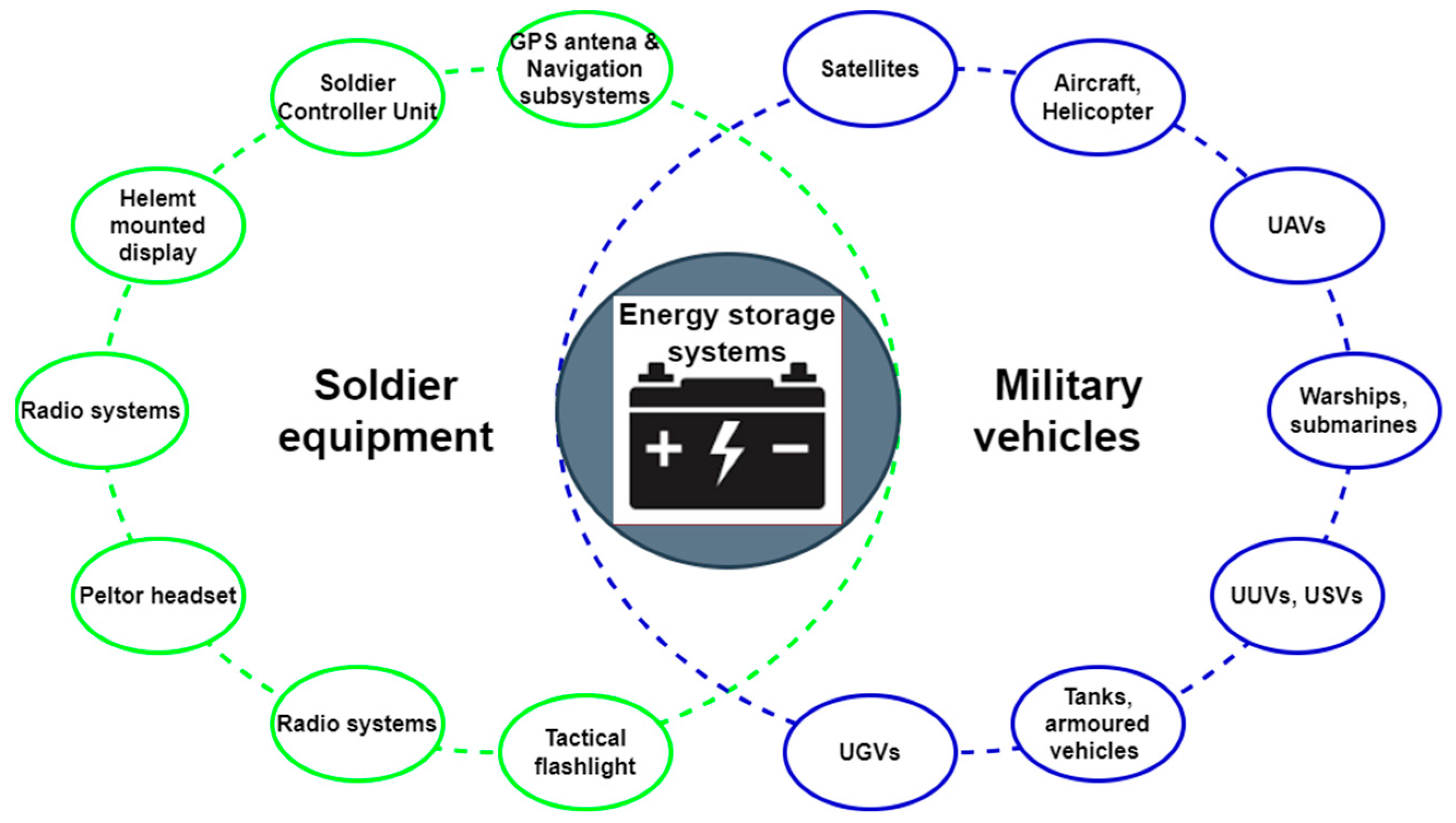
1. Introduction—Use of Batteries in Military Environment
- Artificial Intelligence (AI) and Machine Learning (ML);
- Robotics and Autonomous Systems (RAS);
- Networked sensors and effectors;
- Battlefield electrification;
- Novel weapons.
2. Introduction—Energy Storage Technologies
2.1. Classification of Energy Storage Technologies
2.2. Construction of Selected Battery Technologies
- The anode (negative electrode) is oxidized during the electrochemical reaction and gives up the electrons to the external circuit (external load).
- The cathode (positive electrode) is reduced during the electrochemical reaction and accepts electrons from the external circuit (external load).
- The electrolyte (ionic conductor) provides the medium for transferring electric charge/ions inside the battery between the anode and cathode.
2.2.1. Lead-Acid Batteries
2.2.2. Nickel Batteries
2.2.3. Lithium-Ion Batteries
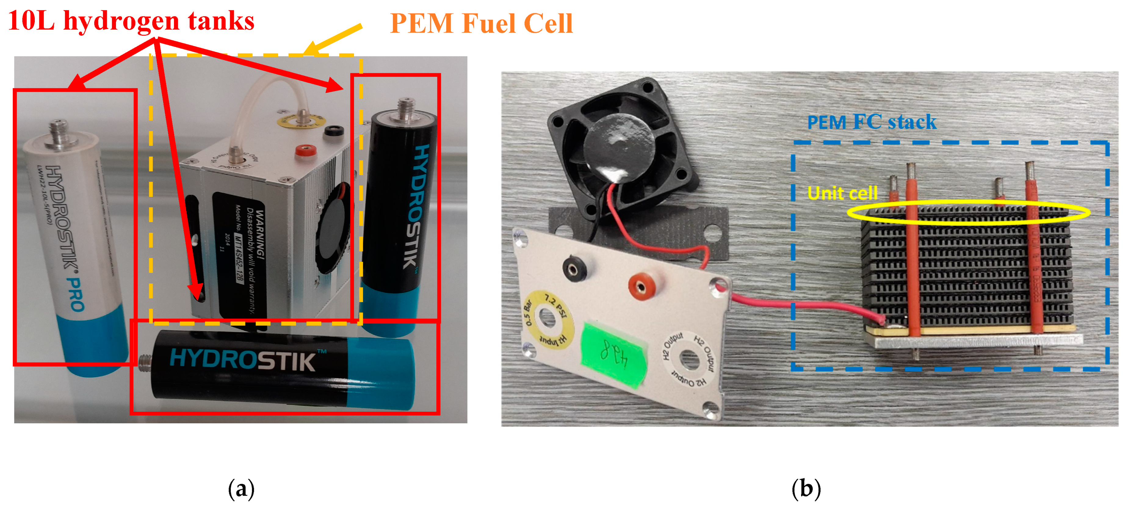
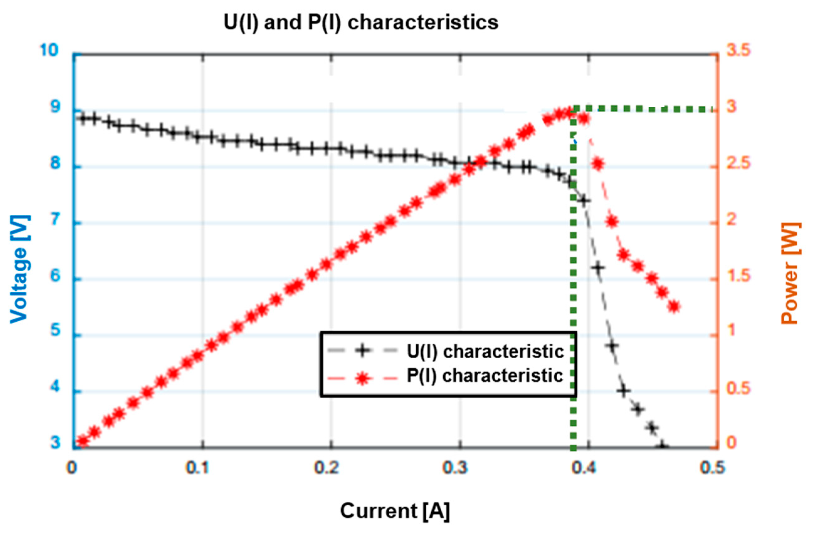
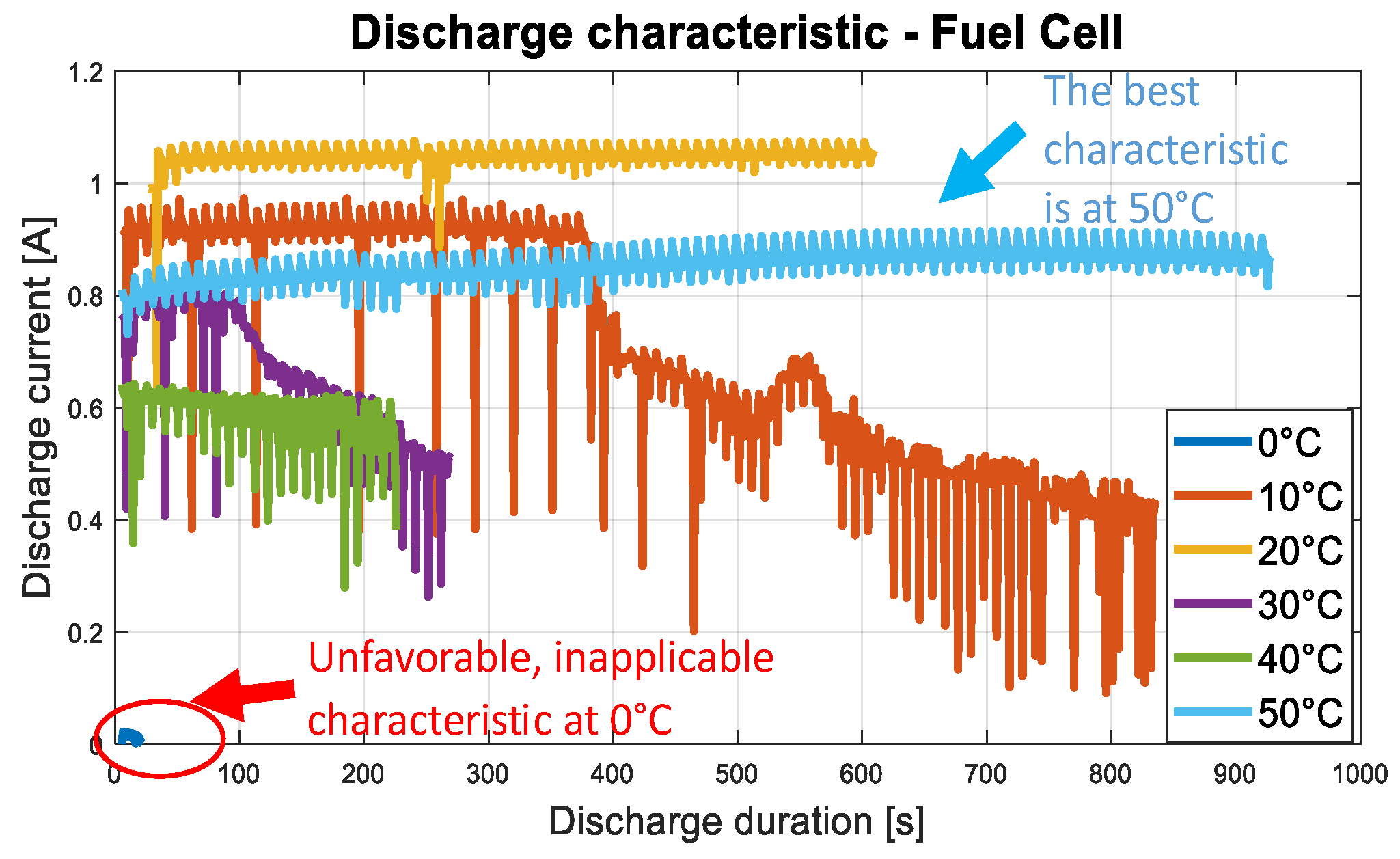
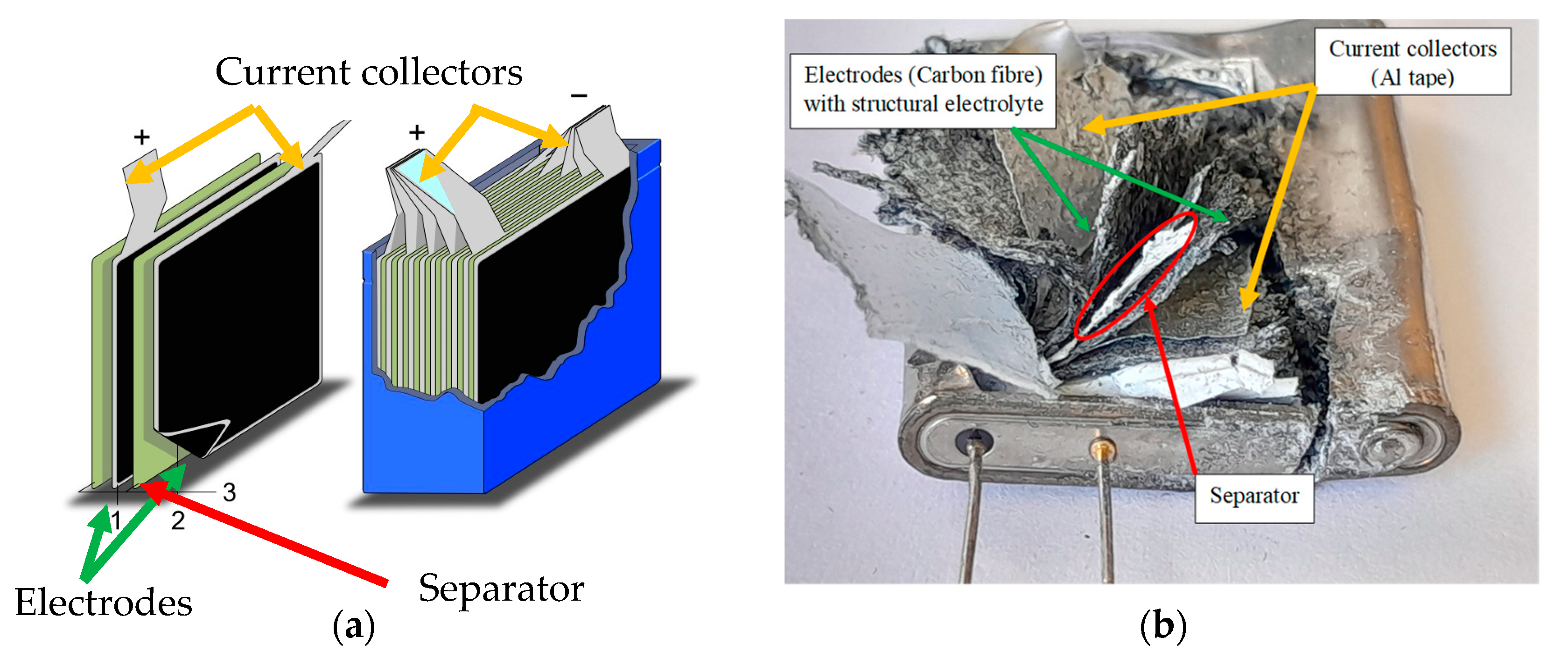
2.3. Fuel Cell and Supercapacitor Construction
3. Experimental Comparison of Selected Battery Technologies
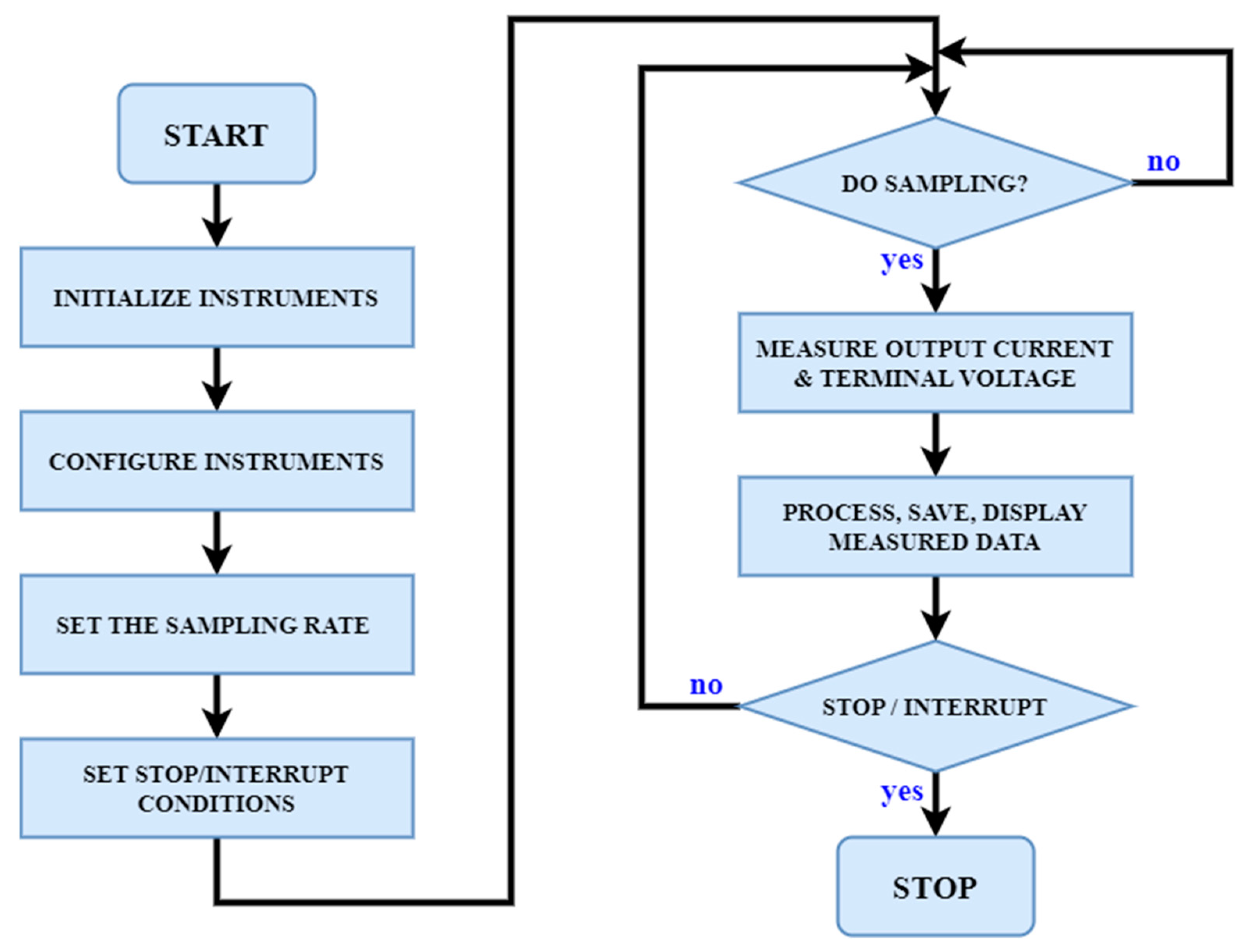
3.1. Battery Testing Methods
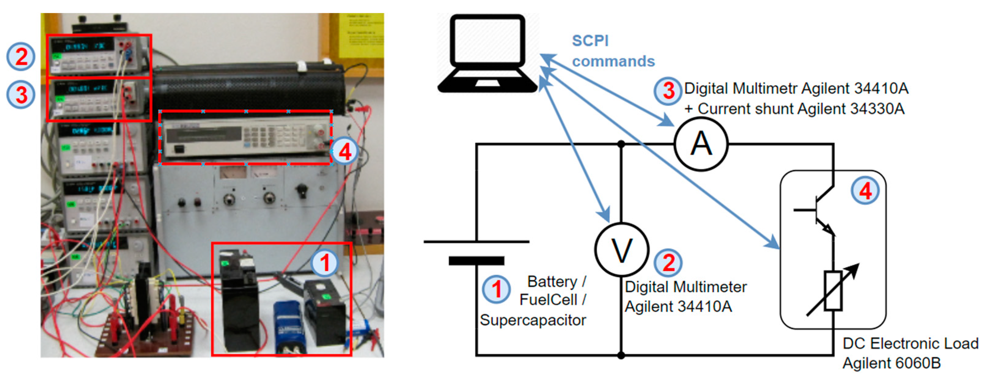
3.2. Experiment Methodology and Setup
3.3. Lead-Acid Battery
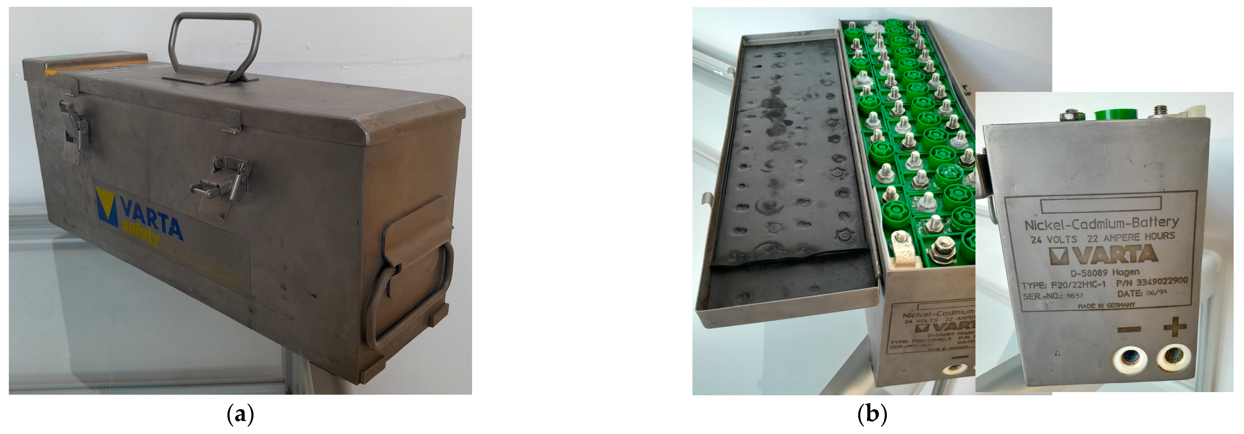
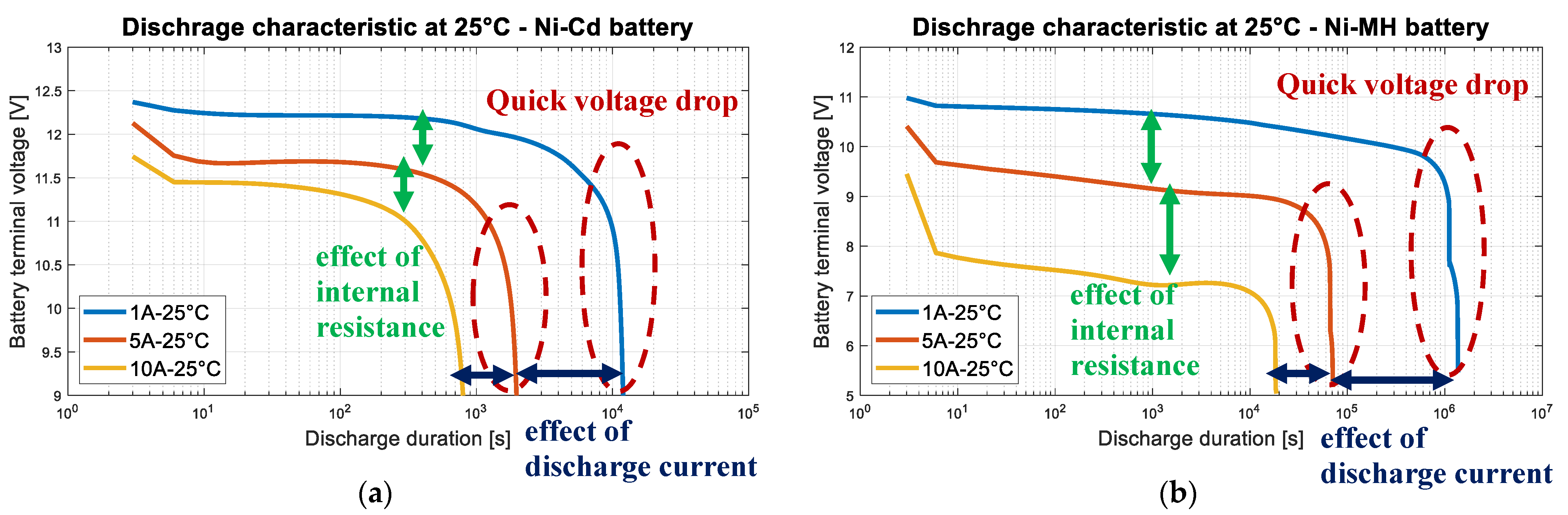
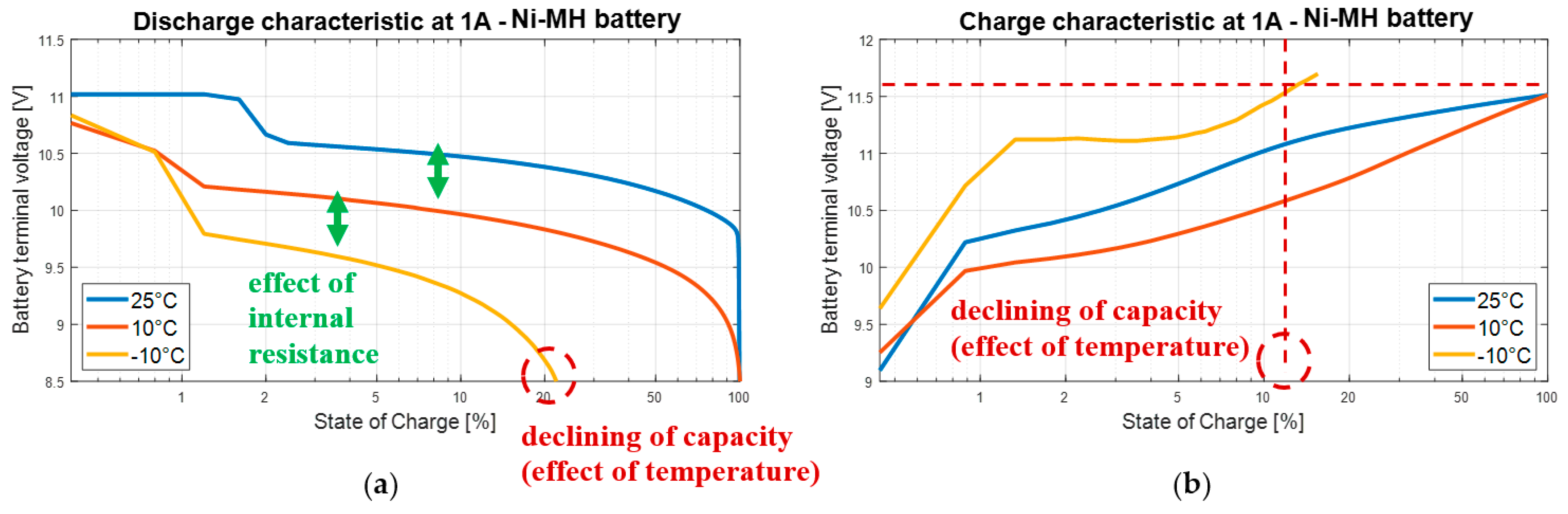
3.4. Nickel Batteries
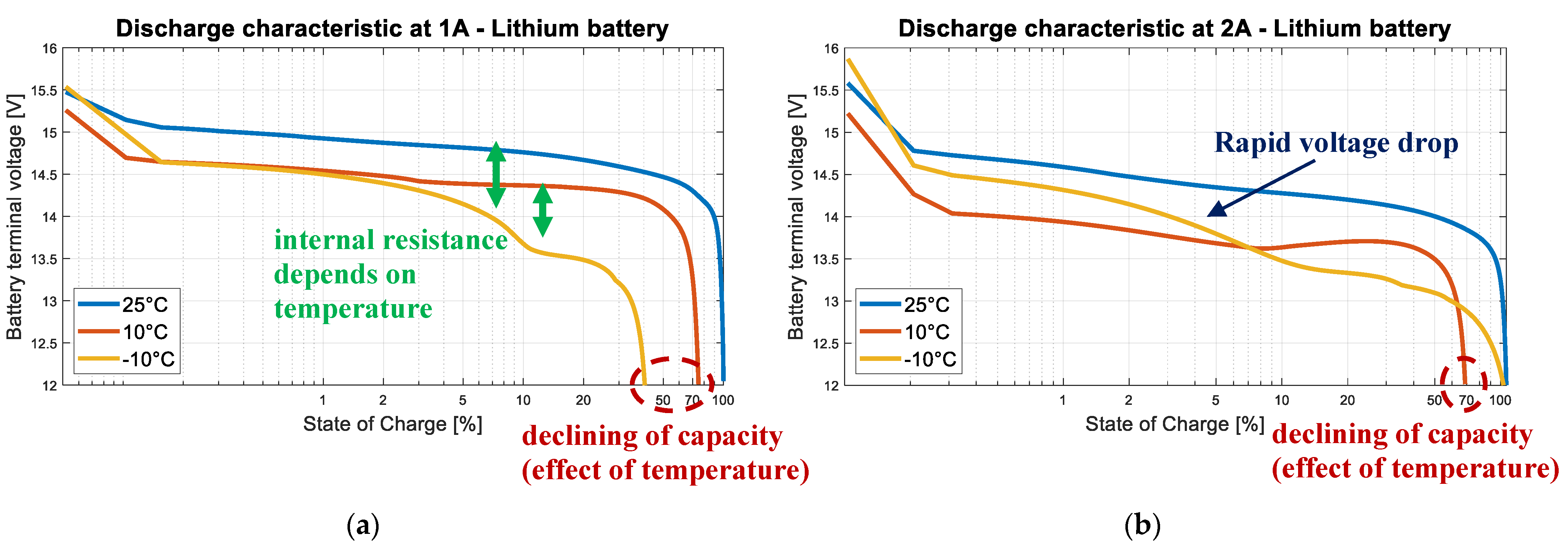
3.5. Lithium-Ion Batteries
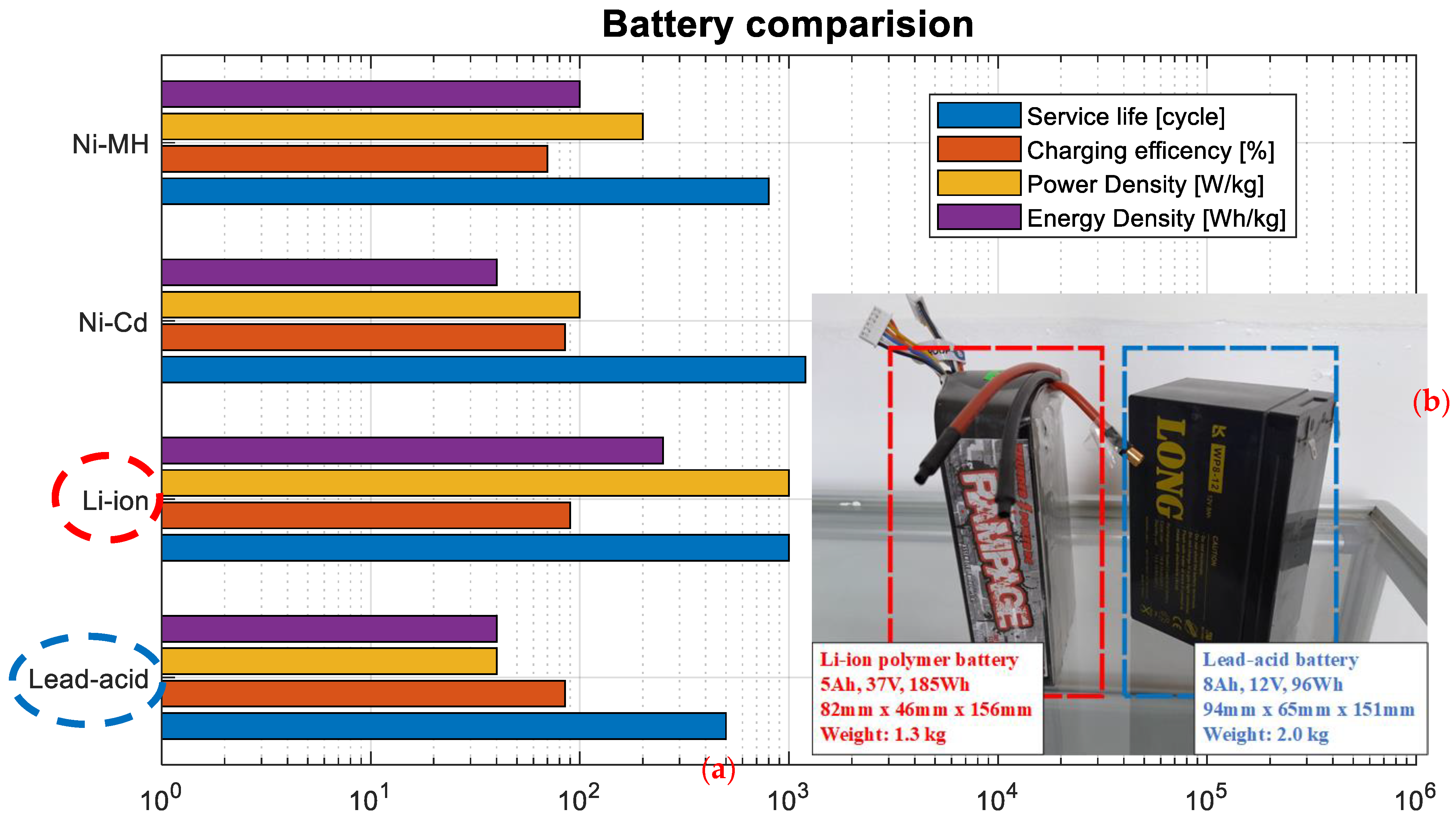
3.6. Partial Conclusion
4. Discussion, Conclusions, and Future Work
4.1. Discussion
4.2. Conclusions
4.3. Future Work
Author Contributions
Funding
Data Availability Statement
Acknowledgments
Conflicts of Interest
References
- Siegel, N.G.; Madni, A.M. The digital battlefield: A behind-the-scenes look from a systems perspective. Procedia Comput. Sci. 2014, 28, 799–808. [Google Scholar] [CrossRef]
- British Army. BATTLEFIELD ELECTRIFICATION. British Army Approach to Battlefield Electrification. Available online: https://www.army.mod.uk/media/17010/british-army-approach-to-battlefield-electrification.pdf (accessed on 11 December 2023).
- Leuchter, J.; Bauer, P.; Zobaa, A.F.; Bojda, P. An interface converter of hybrid power sources with supercapacitors. In Proceedings of the IECON Proceedings (Industrial Electronics Conference), Glendale, AZ, USA, 7–10 November 2010; pp. 3250–3257. [Google Scholar] [CrossRef]
- Pham, N.N.; Leuchter, J.; Pham, K.L.; Dong, Q.H. Battery Management System for Unmanned Electric Vehicles with CAN BUS and Internet of Things. Vehicles 2022, 4, 639–662. [Google Scholar] [CrossRef]
- Leuchter, J.; Stekly, V. Study on the hybrid power source concept of unmanned aircraft systems. In Proceedings of the 2013 Aviation Technology, Integration, and Operations Conference, Los Angeles, CA, USA, 12–14 August 2013. [Google Scholar] [CrossRef]
- Oman, H. On-board energy and power management on electric vehicles: Effect of battery type. In Proceedings of the 17th DASC. AIAA/IEEE/SAE. Digital Avionics Systems Conference. Proceedings (Cat. No.98CH36267), Bellevue, WA, USA, 31 October–7 November 1998; pp. I43/1–I43/6. [Google Scholar] [CrossRef]
- Gagliardi, F.; Pagano, M.; Maestri, G.; Martone, M.; Tarantino, A. Experimental results of on-board battery-ultracapacitor system for electric vehicle applications. In Proceedings of the IEEE International Symposium on Industrial Electronics, L’Ayuila, Italy, 8–11 July 2002; Volume 1, pp. 93–98. [Google Scholar] [CrossRef]
- Romanenko, I.; Shyshatskyi, A. Analysis of modern condition of military radiocommunication system. Adv. Inf. Syst. 2017, 1, 28–33. [Google Scholar] [CrossRef]
- Lopatka, M.J. UGV for close support dismounted operations—Current possibility to fulfil military demand. Chall. Natl. Def. Contemp. Geopolit. Situat. 2020, 2020, 16–23. [Google Scholar] [CrossRef]
- Leuchter, J. Bi-Directional DC-DC Converters for Battery Buffers with Supercapacitor. In Energy Storage in the Emerging Era of Smart Grids; IntechOpen: Rijeka, Croatia, 2011. [Google Scholar] [CrossRef]
- Kalaiselvam, S.; Parameshwaran, R. Energy Storage. In Thermal Energy Storage Technologies for Sustainability; Elsevier: Amsterdam, The Netherlands, 2014; pp. 21–56. [Google Scholar] [CrossRef]
- Mansour, D.E.A. Energy Storage Technologies in MVDC Microgrids. In Medium-Voltage Direct Current Grid: Resilient Operation, Control and Protection; Elsevier: Amsterdam, The Netherlands, 2019; pp. 189–207. [Google Scholar] [CrossRef]
- Hussain, F.; Rahman, M.Z.; Sivasengaran, A.N.; Hasanuzzaman, M. Energy storage technologies. In Energy for Sustainable Development: Demand, Supply, Conversion and Management; Elsevier: Amsterdam, The Netherlands, 2020; pp. 125–165. [Google Scholar] [CrossRef]
- Haidl, P.; Buchroithner, A.; Schweighofer, B.; Bader, M.; Wegleiter, H. Lifetime Analysis of Energy Storage Systems for Sustainable Transportation. Sustainability 2019, 11, 6731. [Google Scholar] [CrossRef]
- Classification of Energy Storage Technologies: An Overview. Available online: https://etn.news/energy-storage/classification-of-energy-storage-technologies-an-overview (accessed on 16 January 2023).
- Beard, K.W.; Reddy, T.B. (Eds.) Linden’s Handbook of Batteries, 5th ed.; McGraw-Hill: New York, NY, USA, 2019; ISBN 978-1-260-11592-5. [Google Scholar]
- Wang, G.; Leng, X.; Han, S.; Shao, Y.; Wei, S.; Liu, Y.; Lian, J.; Jiang, Q. How to improve the stability and rate performance of lithium-ion batteries with transition metal oxide anodes. J. Mater. Res. 2017, 32, 16–36. [Google Scholar] [CrossRef]
- Barbosa, J.C.; Gonçalves, R.; Costa, C.M.; Lanceros-Mendez, S. Recent Advances on Materials for Lithium-Ion Batteries. Energies 2021, 14, 3145. [Google Scholar] [CrossRef]
- Denton, T. Automobile Electrical and Electronic Systems; SAE International: Warrendale, PA, USA, 1995. [Google Scholar]
- Zhu, T.; Boyles, S.D.; Unnikrishnan, A. Electric Vehicle Travelling Salesman Problem with Drone 1 2 3 4. 2019. Available online: https://par.nsf.gov/servlets/purl/10185815 (accessed on 6 April 2022).
- Leuchter, J.; Zobaa, A.F. Batteries investigations of small unmanned aircraft vehicles. In Proceedings of the 2015 International Conference on Clean Electrical Power (ICCEP), Glasgow, UK, 19–21 April 2016; IET—The Institution of Engineering and Technology: London, UK, 2016. [Google Scholar] [CrossRef]
- Heligman, B.T.; Manthiram, A. Elemental Foil Anodes for Lithium-Ion Batteries. ACS Energy Lett. 2021, 6, 2666–2672. [Google Scholar] [CrossRef]
- Park, S.-Y.; Miwa, H.; Clark, B.T.; Ditzler, D.S.K.; Malone, G.; D’Souza, N.S.; Lai, J.-S. A universal battery charging algorithm for Ni-Cd, Ni-MH, SLA, and Li-Ion for wide range voltage in portable applications. In Proceedings of the 2008 IEEE Power Electronics Specialists Conference, Rhodes, Greece, 15–19 June 2008; pp. 4689–4694. [Google Scholar] [CrossRef]
- Org, W.E.; Pierozynski, B. Electrochemical science on the Low Temperature Performance of Nickel-Metal Hydride (NiMH) Batteries. Int. J. Electrochem. Sci. 2011, 6, 860–866. [Google Scholar]
- Qi, G.; Nguyen, S.; Anthony, D.B.; Kucernak, A.R.J.; Shaffer, M.S.P.; Greenhalgh, E.S. The influence of fabrication parameters on the electrochemical performance of multifunctional structural supercapacitors. Multifunct. Mater. 2021, 4, 34001. [Google Scholar] [CrossRef]
- Singhal, S.P.; Alsbach, W.G.; Rao, G. Performance of Nickel-Cadmium Batteries on the Goes i–k Series of Weather Satellites; NASA: Washington, DC, USA, 1998. [Google Scholar]
- Liu, R. Nanostructured Vanadium Pentoxide (V2O5) and Hematite (α-Fe2O3) Hollow Spheres as Electrode Materials for Lithium-Ion Batteries. Master’s Thesis, University of Wollongong, Wollongong, Austraila, 2010. [Google Scholar]
- Battery Test Methods—Battery University. Available online: https://batteryuniversity.com/article/battery-test-methods (accessed on 11 December 2023).
- Pramanik, P.K.D.; Sinhababu, N.; Mukherjee, B.; Padmanaban, S.; Maity, A.; Upadhyaya, B.K.; Holm-Nielsen, J.B.; Choudhury, P. Power Consumption Analysis, Measurement, Management, and Issues: A State-of-the-Art Review of Smartphone Battery and Energy Usage. IEEE Access 2019, 7, 182113–182172. [Google Scholar] [CrossRef]
- Leuchter, J.; Stekl, V.; Bauer, P. Battery-supercapacitors mixed as electrical power buffers. In Proceedings of the 5th IET International Conference on Power Electronics, Machines and Drives (PEMD 2010), Brighton, UK, 19–21 April 2010; Volume 2010. [Google Scholar] [CrossRef]
- Zahran, M.; Atef, A. Electrical and Thermal Properties of NiCd Battery for Low Earth Orbit Satellite’s Applications. WSEAS Trans. Electron. 2006, 3, 340. [Google Scholar]
- Xu, Y.; Lu, W.; Xu, G.; Chou, T.-W. Structural supercapacitor composites: A review. Compos. Sci. Technol. 2021, 204, 108636. [Google Scholar] [CrossRef]
- Supercapacitor Options for Energy-Harvesting|DigiKey. Available online: https://www.digikey.kr/ko/articles/supercapacitor-options-for-energy-harvesting-systems (accessed on 7 February 2023).
- Axsen, J.; Burke, A.F.; Kurani, K.S. Batteries for PHEVs: Comparing Goals and the State of Technology. In Electric and Hybrid Vehicles: Power Sources, Models, Sustainability, Infrastructure and the Market; Elsevier: Amsterdam, The Netherlands, 2010; pp. 405–427. [Google Scholar] [CrossRef]
- Bae, S.-H.; Jeon, C.; Oh, S.; Kim, C.-G.; Seo, M.; Oh, I.-K. Load-bearing supercapacitor based on bicontinuous PEO-b-P(S-co-DVB) structural electrolyte integrated with conductive nanowire-carbon fiber electrodes. Carbon 2018, 139, 10–20. [Google Scholar] [CrossRef]
- Lin, S.-L.; Huang, K.-L.; Wang, I.-C.; Chou, I.-C.; Kuo, Y.-M.; Hung, C.-H.; Lin, C. Characterization of spent nickel–metal hydride batteries and a preliminary economic evaluation of the recovery processes. J. Air Waste Manag. Assoc. 2016, 66, 296–306. [Google Scholar] [CrossRef] [PubMed]
- Young, K.-H.; Cai, X.; Chang, S. Reviews on Chinese Patents Regarding the Nickel/Metal Hydride Battery. Batteries 2017, 3, 24. [Google Scholar] [CrossRef]
- Chang, S.; Young, K.-H.; Nei, J.; Fierro, C. Reviews on the U.S. patents regarding nickel/metal hydride batteries. Batteries 2016, 2, 10. [Google Scholar] [CrossRef]
- Olabi, A.G.; Abbas, Q.; Shinde, P.A.; Abdelkareem, M.A. Rechargeable batteries: Technological advancement, challenges, current and emerging applications. Energy 2023, 266, 126408. [Google Scholar] [CrossRef]
- el Haj Assad, M.; Khosravi, A.; Malekan, M.; Rosen, M.A.; Nazari, M.A. Energy storage. In Design and Performance Optimization of Renewable Energy Systems; Elsevier: Amsterdam, The Netherlands, 2021; pp. 205–219. [Google Scholar] [CrossRef]
- Laadjal, K.; Cardoso, A.J.M. Estimation of Lithium-Ion Batteries State-Condition in Electric Vehicle Applications: Issues and State of the Art. Electronics 2021, 10, 1588. [Google Scholar] [CrossRef]
- Leuchter, J.; Bauer, P. Capacity of power-batteries versus temperature. In Proceedings of the 2015 17th European Conference on Power Electronics and Applications, EPE-ECCE Europe 2015, Geneva, Switzerland, 8–10 September 2015. [Google Scholar] [CrossRef]
- Gabbar, H.A.; Othman, A.M.; Abdussami, M.R. Review of Battery Management Systems (BMS) Development and Industrial Standards. Technologies 2021, 9, 28. [Google Scholar] [CrossRef]
- Chen, Y.; Kang, Y.; Zhao, Y.; Wang, L.; Liu, J.; Li, Y.; Liang, Z.; He, X.; Li, X.; Tavajohi, N.; et al. A review of lithium-ion battery safety concerns: The issues, strategies, and testing standards. J. Energy Chem. 2021, 59, 83–99. [Google Scholar] [CrossRef]
- Wen, J.; Yu, Y.; Chen, C. A Review on Lithium-Ion Batteries Safety Issues: Existing Problems and Possible Solutions. Mater. Express 2022, 43, 32. [Google Scholar] [CrossRef]
- Lamb, J.; Jeevarajan, J.A. New developments in battery safety for large-scale systems. MRS Bull. 2021, 46, 395. [Google Scholar] [CrossRef]
- Wang, Q.; Zhao, H.; Ould Ely, T.; Ely, O.T.; Kamzabek, D.; Chakraborty, D. Batteries Safety: Recent Progress and Current Challenges. Front. Energy Res. 2019, 7, 71. [Google Scholar] [CrossRef]
- Sripad, S.; Bills, A.; Viswanathan, V. A review of safety considerations for batteries in aircraft with electric propulsion. MRS Bull. 2021, 46, 435. [Google Scholar] [CrossRef]
- Amin; Bambang, R.T.; Rohman, A.S.; Dronkers, C.J.; Ortega, R.; Sasongko, A. Energy management of fuel cell/battery/supercapacitor hybrid power sources using model predictive control. IEEE Trans. Ind. Inform. 2014, 10, 1992–2002. [Google Scholar] [CrossRef]
- Ratha, S.; Sahoo, S.; Mane, P.; Polai, B.; Sathpathy, B.; Chakraborty, B.; Nayak, S.K. Experimental and computational investigation on the charge storage performance of a novel Al2O3-reduced graphene oxide hybrid electrode. Sci. Rep. 2023, 13, 5283. [Google Scholar] [CrossRef]
- Sahoo, S.; Ratha, S.; Rout, C.S.; Nayak, S.K. Self-charging supercapacitors for smart electronic devices: A concise review on the recent trends and future sustainability. J. Mater. Sci. 2022, 57, 4399–4440. [Google Scholar] [CrossRef]


| Classes | Weight | Carry/Transport | Payload |
|---|---|---|---|
| Throwable UGVs | Up to 2 kg | Very limited payload | |
| Backpackable UGVs | Up to 25 kg | Can be carried by 1 man | Up to 5–10 kg |
| Portable UGVs | Up to 75 kg | Can be transported by any vehicle, and Can be loaded/reloaded by 2 men | Up to 30 kg |
| Light UGVs | Up to 300 kg | Can be transported in adapted vehicles | Up to 150–200 kg |
| Medium UGVs | Up to 1000 kg | Can be transported by trailer/adapted vehicles | Up to 300–500 kg |
| Heavy UGVs | Up to 5000 kg | Can be transported on the trailer/towed | Up to 2000 kg |
| Very heavy UGVs | Above 5000 kg | Can be transported on the trailer/towed |
| FC Types | Short Name | Electrolyte | Operating Temperature | Main Features |
|---|---|---|---|---|
| Solid Oxide | SOFC | Solid oxygen-ion-conducting metal oxide | 1000 °C | Efficiency up to 60%, high-grade heat generation |
| Molten Carbonate | MCFC | Mixed alkali-carbonate, molten salt | 650 °C | has been developed for continuously operating facilities and can use coal-based/marine diesel fuels |
| Phosphoric Acid | PAFC | Concentrated phosphoric acid | 230 °C | Efficiency up to 85% (40% electricity, 45% heat) |
| Alkaline | AFC | Alkaline potassium hydroxide | 70 °C | Efficiency up to 60%, used by NASA on the manned space missions |
| Proton exchange membrane | PEM | Perfluorinated ionomer polymer membrane | 70–85 °C | Rapid startup time has been designed for transportable and low-kW system |
| Direct methanol | DMFC | Perfluorinated ionomer polymer membrane | 70–85 °C | Rapid startup time has been designed for transportable and sub-kW system |
| Regenerative | RFC | Closed-loop generator—an electrolyzer separates water into hydrogen and oxygen, which are then used to produce electricity and water by FC |
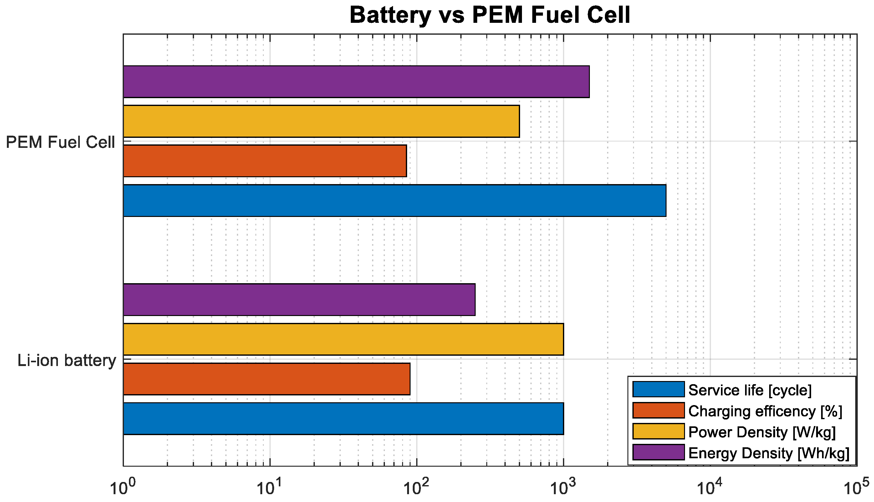
| FC Types | Lead-Acid | Ni-Cd | Ni-MH | Li-Ion | Supercapacitor | PEM FC |
|---|---|---|---|---|---|---|
| Energy Density [Wh/kg] | <60 | <60 | 100 | >200 | <30 | Up to 40 k |
| Power Density [W/kg] | <60 | 100 | <200 | Up to 1000 | Up to 100 k | <60 |
| Charging Efficiency [%] | Up to 80% | Up to 90% | <70% | Up to 90% | Up to 80% | Up to 90% |
| Service Life [cycle] | 500 | >1000 | 800 | 1000 | 100,000 | 1000 |
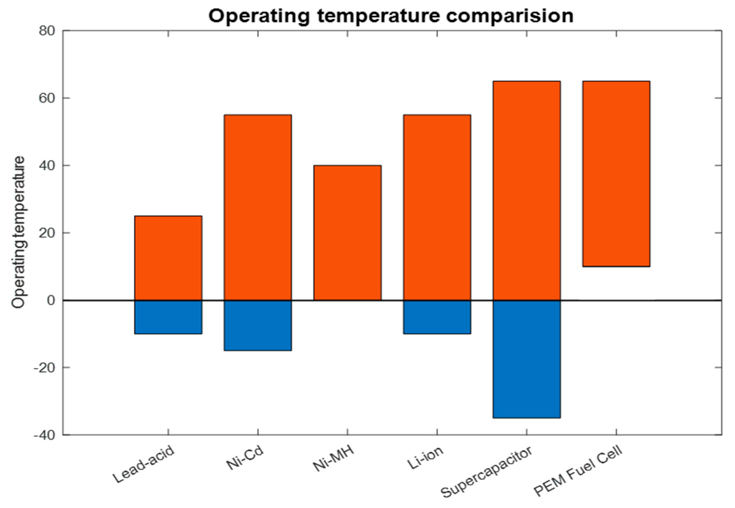
| Operating Temperature [°C] | −10–25 | −15–50 | 0–40 | −10–50 | −35–65 | >25 |
Disclaimer/Publisher’s Note: The statements, opinions and data contained in all publications are solely those of the individual author(s) and contributor(s) and not of MDPI and/or the editor(s). MDPI and/or the editor(s) disclaim responsibility for any injury to people or property resulting from any ideas, methods, instructions or products referred to in the content. |
© 2024 by the authors. Licensee MDPI, Basel, Switzerland. This article is an open access article distributed under the terms and conditions of the Creative Commons Attribution (CC BY) license (https://creativecommons.org/licenses/by/4.0/).
Share and Cite
Pham, N.N.; Bloudicek, R.; Leuchter, J.; Rydlo, S.; Dong, Q.H. Comparative Analysis of Energy Storage and Buffer Units for Electric Military Vehicle: Survey of Experimental Results. Batteries 2024, 10, 43. https://doi.org/10.3390/batteries10020043
Pham NN, Bloudicek R, Leuchter J, Rydlo S, Dong QH. Comparative Analysis of Energy Storage and Buffer Units for Electric Military Vehicle: Survey of Experimental Results. Batteries. 2024; 10(2):43. https://doi.org/10.3390/batteries10020043
Chicago/Turabian StylePham, Ngoc Nam, Radim Bloudicek, Jan Leuchter, Stanislav Rydlo, and Quang Huy Dong. 2024. "Comparative Analysis of Energy Storage and Buffer Units for Electric Military Vehicle: Survey of Experimental Results" Batteries 10, no. 2: 43. https://doi.org/10.3390/batteries10020043