Review

Welding Challenges and Quality Assurance in Electric Vehicle Battery Pack Manufacturing

by
Panagiotis Stavropoulos
*,
Kyriakos Sabatakakis
and
Harry Bikas
Laboratory for Manufacturing Systems and Automation (LMS), Department of Mechanical Engineering and Aeronautics, University of Patras, Rio, 26504 Patras, Greece
*
Author to whom correspondence should be addressed.
Batteries 2024, 10(5), 146; https://doi.org/10.3390/batteries10050146
Submission received: 29 January 2024 / Revised: 27 March 2024 / Accepted: 19 April 2024 / Published: 24 April 2024
(This article belongs to the Section Battery Processing, Manufacturing and Recycling)

Abstract

:
Electric vehicles’ batteries, referred to as Battery Packs (BPs), are composed of interconnected battery cells and modules. The utilisation of different materials, configurations, and welding processes forms a plethora of different applications. This level of diversity along with the low maturity of welding designs and the lack of standardisation result in great variations in the mechanical and electrical quality of the joints. Moreover, the high-volume production requirements, meaning the high number of joints per module/BP, increase the absolute number of defects. The first part of this study focuses on associating the challenges of welding application in battery assembly with the key performance indicators of the joints. The second part reviews the existing methods for quality assurance which concerns the joining of battery cells and busbars. Additionally, the second part of this paper identifies the general trends and the research gaps for the most widely adopted welding methods in this domain, while it renders the future directions.

Graphical Abstract

1. Introduction

1.1. Significance

Climate change is reshaping the automotive industry, as breakthroughs in battery technologies and initiatives drive the shift from internal combustion vehicles to fully electric ones [1]. In 2022, the electric car markets experienced exponential growth as sales exceeded 10 million with the electrification of road transport extending beyond cars. As a consequence, the demand for lithium-ion (Li-ion) for automotive applications increased by 65%, from around 330 GWh in 2021 to 550 GWh in 2022, mainly due to the growth in the sales of electric passenger cars, with new registrations increasing by 55% in 2022 compared to 2021 [2] (see Figure 1). In Europe alone, the Commission announced in December 2023 a EUR 3 billion fund to boost the battery manufacturing industry for the next 3 years [3].
To this end, automotive original equipment manufacturers (OEMs) and battery cell manufacturers have invested and will continue to invest billions in battery cell development and battery cell manufacturing plants. However, to turn this investment into a sustainable business, battery cost reductions are needed to eliminate the high direct costs of battery electric vehicles (BEVs) compared to internal combustion engine vehicles (ICEVs) [4]. The battery cost can be as high as one-third of the total vehicle cost as shown in Figure 2 [5]. In terms of battery manufacturing costs, the largest part is cell manufacturing and the second largest part is battery materials. An example analysis of the popular lithium manganese oxide-graphite pack used in the Nissan Leaf and Chevrolet Volt showed that the specific energy consumption for the 24 kWh battery pack is 50.17 kWh/kg. Of this, 38% of the energy is consumed by the electrode drying process and 43% by the dry room equipment. The energy consumption of the battery pack assembly process was only 0.03 kWh/kg during the battery pack production [6].
However, the assembly of a battery pack is a critical process for the major OEMs. This type of assembly application presents massive challenges in terms of automating the manufacturing processes that have little in common with the classic and mature body-in-white assembly lines. Variations between joints can affect the performance of the battery or, at best, lead to scrap during assembly, but can also have catastrophic consequences, even if the cause is a single faulty joint.
The cost figures mentioned above also show that the environmental footprint of BEVs is mainly due to their production. This footprint becomes even larger when the maintenance of the vehicle’s battery is taken into account (ageing of the battery over a finite number of charge–discharge cycles [7]), where the entire battery back has to be replaced. As a result, the lifecycle environmental footprint of the BEV is only marginally lower than that of an ICEV, and then only under very specific conditions, i.e., using renewable charging sources [8,9].
In addition to the economic and political importance of BEV battery production, the performance requirements of BEV batteries pose several challenges from a technology and research perspective. For example, the operational objectives of the Batteries European Partnership Association (BEPA) aim to achieve several goals by 2030, such as increasing the energy density of batteries, increasing their power density and charging rate, improving the cycle time between battery replacements, reducing the overall cost of batteries, ensuring the safety of batteries for different applications, implementing advanced technologies in manufacturing and recycling operations, and finally improving the sustainability of battery raw material supply chains and achieving the lowest possible carbon footprint throughout the value chain [3]. All these objectives present challenges in different areas, such as the introduction of new cell technologies, research into advanced materials and processes, improvement of assembly applications, and quality assurance.

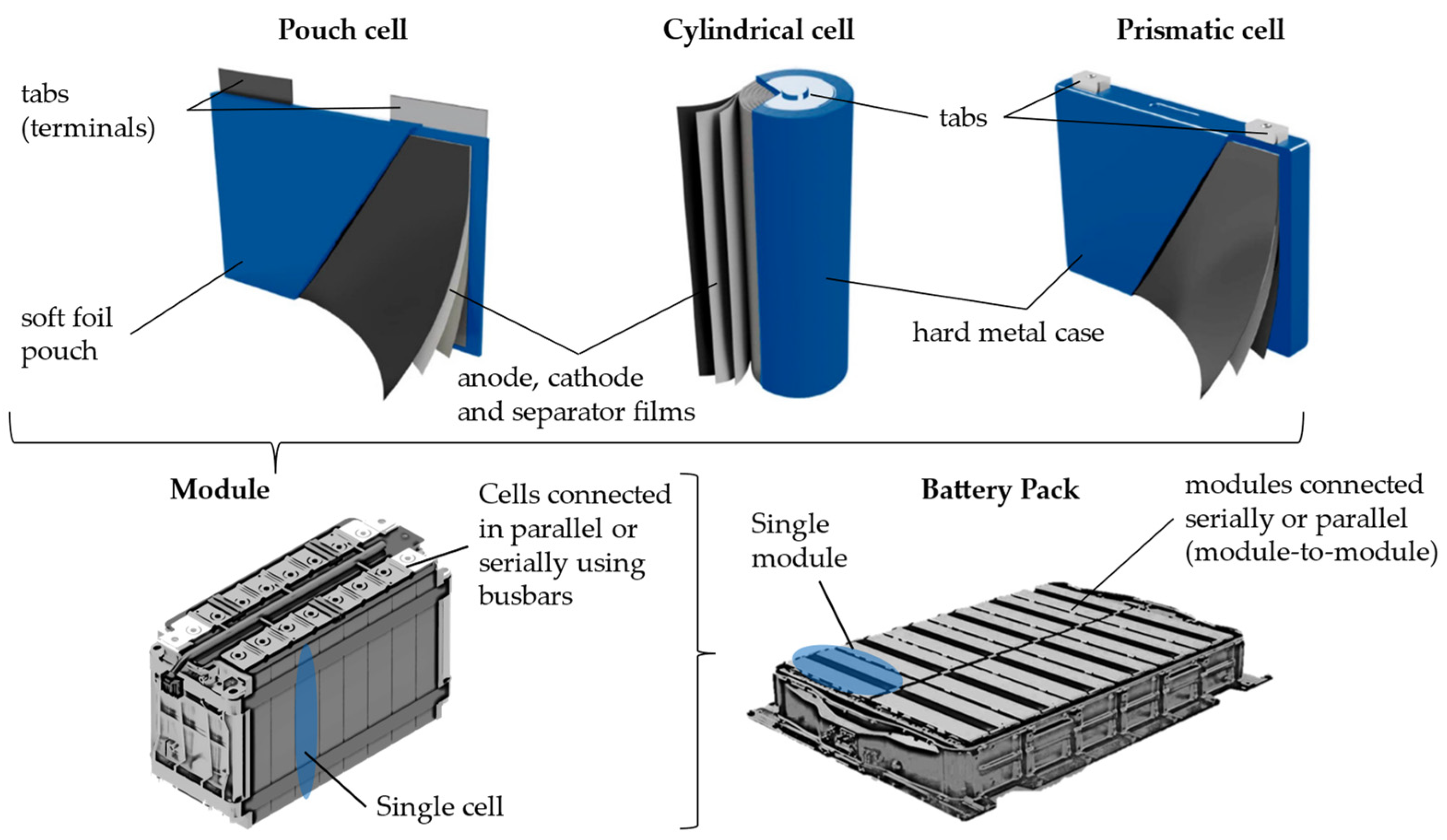
1.2. EV Battery Architecture

A battery pack is made up of battery modules, each one containing a number of battery cells. The joints that form these connections between the battery tabs and busbars are made from thin materials and are typically lap, fillet, or spot welded. This makes their assembly process a critical aspect of battery pack manufacturing and plays a vital role in the overall performance and reliability of the battery system. Different welding processes are used depending on the design and requirements of each battery pack or module. Joints are also made to join the internal anode and cathode foils of battery cells, with ultrasonic welding (UW) being the preferred method for pouch cells.
Currently, OEMs are pursuing several different designs and configurations to meet the different performance and operating criteria of each battery pack. So, while there are common approaches to materials and powertrain technologies, a truly standardised industrial approach to BEV battery assembly is still in its infancy. Unsurprisingly, there are many small differences in the structures, materials, and systems that need to be considered in the assembly processes [10]. However, one thing that can be said with certainty is that a battery pack, and more specifically a battery module, is made up of a single type of cell, i.e., pouch, cylindrical, or prismatic cells. Each type has its peculiarities when it comes to assembling the corresponding module as can be seen in Figure 3. The two most common metal-to-metal joints for battery pack assembly are referred to as Tab-to-Tab (T2T) and Tab-to-Busbar (T2B). T2T refers to the joint between two or more tabs while T2B refers to the joint between one or more tabs and a busbar. The tab materials include Al, Cu, and Ni with Al tabs most commonly used for the cathode and Ni-plated Cu tabs to be used as the anode material [11]. As mentioned above, another type of joint is the foil-to-tab weld which is required to collect all the current collector plates (foils) inside the cell and join them to a tab [12]. Finally, while there are many lithium-based cell chemistries, the most widely used at present are the Li-ion chemistries which have replaced another popular chemistry of the past, nickel metal hydride (NiMH).

1.3. Joining Applications

UW, resistance spot welding (RSW), laser welding (LW), and wire bonding (WB) are the most used and investigated joining processes in the industry and research community. Other joining methods such as micro-tungsten-inert-gas welding (micro-TIG), micro-clinching, soldering, and magnetic-pulse welding exist and have been proposed for battery assembly applications, but they are not well established, and therefore their feasibility is still being evaluated, or they are not widely used in the industry. Mechanical fastening is another method of joining electrical components in the BEV’s powertrain, but in the context of battery pack assembly, it is mainly used for the assembly of modules. The following paragraphs provide some brief but informative descriptions of each of the four most commonly used welding methods for battery module assembly.
In UW (Figure 4a), two or more thin sheets to be welded are typically pressed together, and ultrasonic vibration is applied perpendicular to the direction of the force to form a solid state joint. The main feature of the process is that the materials involved are not melted. Thus, unwanted properties due to the state stage of the material [14] favour the formation of an atomic bond at elevated temperatures [15]. UW is mainly used for lap joints in battery welding of dissimilar soft, highly conductive and reflective soft metals such as Al, Cu, brass, Ag, and Au and especially for joining stacked thin cell foils to tabs (Figure 4b). Another advantage of UW is that it does not promote metallurgical defects such as the formation of intermetallic compounds (IMCs) and porosity, while typically, UW creates larger contact areas. However, classic UW requires two-sided access, making it suitable for a limited number of battery assembly designs such as the welding of multiple pouch cell tabs to a busbar (Figure 4c). One-sided variants of the process called WB exist and concern the welding of thin wire onto cylindrical cell tabs(Figure 4d,e).
WB or ultrasonic wedge bonding is a joining technology widely used in the electronics industry for joining microelectronic components [16]. For battery assembly, it can be thought of as a one-sided UW variant (Figure 4d), where the sonotrode or wedge presses a thin Al, Cu, or Au wire (typically less than 0.5 mm) against the tab of a cell and applies ultrasonic vibration to create a similar type of joint to that in UW. WB is a relatively fast and inexpensive technology for welding cylindrical cell tabs to busbars (Figure 4e) and has the same advantages as UW, i.e., it does not cause microstructural changes to the materials as there is no melting. WB is a highly flexible and reconfigurable process, which does not require strict tolerances between the battery components to be welded and can be used to implement different designs without significant changes in process parameters.
Figure 4. Schematic representation of a typical UW process for joining two thin metal sheets [17] (a), UW of anode/foil to the pouch cell terminal (b), UW of multiple pouch cell tabs to busbar (c), Schematic representation of a typical WB a metal wire-to-metal substrate [18] (d), WB of a busbar to a cylindrical cell tab (e).
Batteries 10 00146 g004
In its simplest form, RSW involves two or more sheets of metal being pressed together at a single point (spot) under the mechanical force of two electrodes, thus providing a conductive path for the current (Figure 5a). At the point of contact, the electrical resistance is greater than that of the base metal, causing heat to be induced according to the Joule–Lenz law and forming a molten nugget when a high-amplitude electric current is passed through [19]. As well as being used in high-volume, high-speed production stages such as in Body-In-White (BIW), RSW is also used in battery assembly applications using materials up to 0.4 mm or for joints that will be carrying less than 20 Amps, due to the high electrical conductivity of the workpieces. This limitation, together with the need for double-side access, has been overcome in some cases by using projection RSW, single-sided RSW (Figure 5b–d), and Ni-plated materials [20]. While RSW is used to connect pouch cells and thin busbars to prismatic or cylindrical cells, it is most commonly used in the latter case with only a single layer of material.
In LW (Figure 6), a high-power laser beam, typically with a power density of around 1 MW per square centimetre, is directed to a small spot on the surface of the workpiece to be welded. This beam is partially absorbed and converted into a very localised heat source that locally melts the material and creates a joint [21]. LW offers small heat-affected zones and high welding speeds, making it suitable for high-volume production applications such as BIW and battery assembly. For the latter, infrared lasers (mainly fibre, disc, and diode with power from 400 W to 4 kW) are used in keyhole mode without any particular preference for a specific battery cell type [22], while pilot implementations are investigating the use of blue and green lasers, which seem to solve the absorption problems of non-ferrous materials [23]. LW is mainly used in lap and fillet configurations of steel–Cu, steel–Al, steel–Ni and Al–Cu where the top sheet is quite thin. Other LW variants include superimposed beam oscillation [24] to increase the contact area between the workpieces, the introduction of interlayers/coatings [22], or the use of tailored seam or spot patterns [25] to improve the performance of the joint. The quality of LW is very sensitive, and requires selection of the process parameters, and of course, a tight fit between the workpieces.

1.4. The Purpose of This Study

The purpose of this study is to review the existing studies which address the quality assurance approaches of battery welding applications. More specifically, this review targets the welding applications between battery cell tabs and busbars. In doing so, the authors aim to identify the general trends for LW, UW, RSW, and WB and the gaps in the literature and propose a direction for future research based on the corresponding quality control and production needs. To achieve this, the first part of the review (Section 2) focuses on identifying the factors associated with the quality of welds or otherwise the key performance indicators (KPIs) used in battery module assembly applications. It also identifies the challenges associated with optimising these KPIs and links them to the corresponding welding processes. The second part (Section 3) focuses on reviewing the existing state of practice and state-of-the-art quality assurance approaches that address the aforementioned KPIs and associated challenges. It divides quality assurance into two main classes: monitoring and quality assessment and process optimisation, for each of which a number of representative studies are thoroughly reviewed. Finally, in the last section (Section 4), the authors summarise their findings by identifying common trends along the main themes of the review and by identifying the directions and the technological framework on the basis of which the scientific community would provide answers to questions that have not yet been fully addressed.

2. Key Performance Indicators and Challenges

This section examines the KPIs and challenges associated with the assembly application of battery packs. More specifically, these KPIs and challenges mainly relate to the connection between battery cell tabs (T2T connections) or between battery cell tabs and busbars (T2B connections).

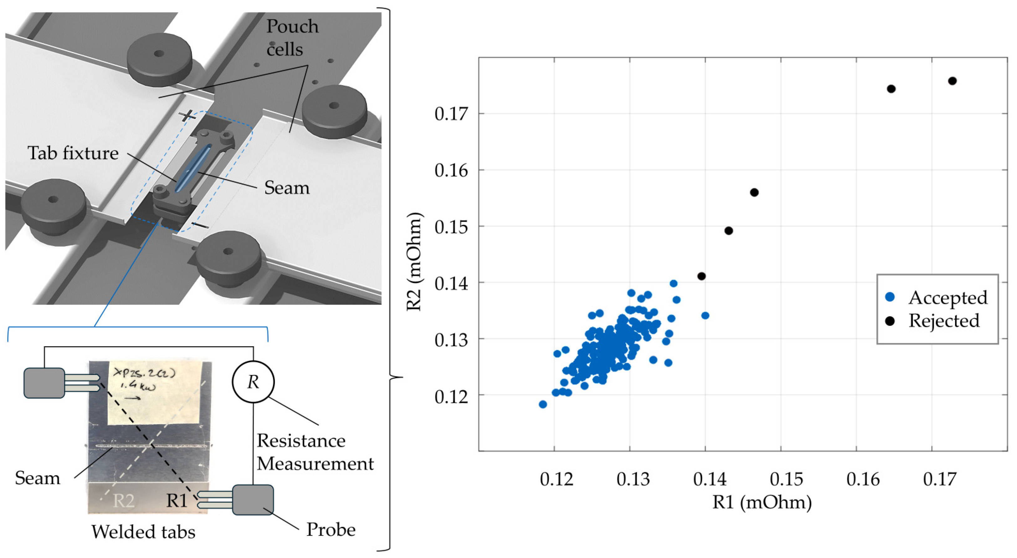
2.1. Electrical Performance

Low electrical resistance means increased efficiency for the entire powertrain and is a fundamental requirement for any electrical connection. Conversely, high electrical resistance causes heat loss during battery charging and discharging (Figure 7). As a result, hot spots (up to 200 °C) develop on these connections and affect the corresponding cells. These high temperatures, in addition to creating positive feedback for higher temperatures to be developed through the increase in electrical resistance, can also lead to premature ageing of the cells and eventually compromise the safe operating limit of most commercial Li-ion battery cells [26]. In addition to these problems, excessive heat generation typically requires larger systems to cool the battery pack. This adds weight to the vehicle and requires more power for the cooling system to operate.
The consistency of electrical quality between the connections of a battery back is also highly desirable, as active voltage equalisation of the cells can also lead to range reduction, heat generation, and accelerated cell ageing [27]. Achieving low contact resistance is an active area of research and involves optimising the joining method used [24]. It has been found that fusion welding applications such as RSW and LW in the binary system of the dissimilar materials involved form multiple IMCs characterised by high resistivity and brittleness. This becomes more severe as the intermetallic layer becomes thicker [28]. Controlling the thickness of this layer or the mixing ratio of such a binary system means controlling the mechanical and electrical properties of these joints [29,30]. However, this poses several challenges due to the (i) low absorptivity of infrared laser light from materials such as Al, Cu, and other non-ferrous metals, (ii) the sudden changes in absorptivity of these materials when changing from solid to liquid, and vice versa [31] (keyhole fluctuations), and (iii) the high thermal conductivity of these materials, and the different expansion rates [13]. On the other hand, it should be noted that although WB does not involve melting, it is likely to produce joints with higher resistivity values compared to the other welding methods, as it is limited by the extremely small cross-sectional area of the wire involved. However, this “disadvantage” has been patented for the use of these joints as fusible links [11] at least in the case of cylindrical cells, where the charge and discharge current is lower due to the high number of cells used per module.

2.2. Welding Temperature

Welding with low heat input is critical to prevent high temperatures from building up in the cells for long periods of time. This is important because temperatures above 60 °C generally cause the Li-ion cell to degrade much more quickly. The development of high temperatures can cause the electrolyte to decompose and break the solid electrolyte interface [32], which in turn can melt or damage the safety vent, compromise seals or cause internal short circuits [13]. Whilst fusion welding processes such as RSW and LW can reach higher temperatures (up to 1500 °C), solid-state welding processes such as UW are likely to produce the same heating result due to their longer process times. While few studies have been carried out on the heat propagation due to tab welding, the authors in [32], by simulating a thermal stress scenario for prismatic cells, concluded that during the LW process, the heat input does not cause thermal stress to the cells, and the temperature developed is low. On the other hand, micro TIG welding, although not found to be used in industrial scenarios, seems to require fine control to avoid overheating the cell [33]. Similarly, direct soldering on a cell tab can potentially cause thermal shock, especially if the liquidus temperature of the solder exceeds 150 °C [11].

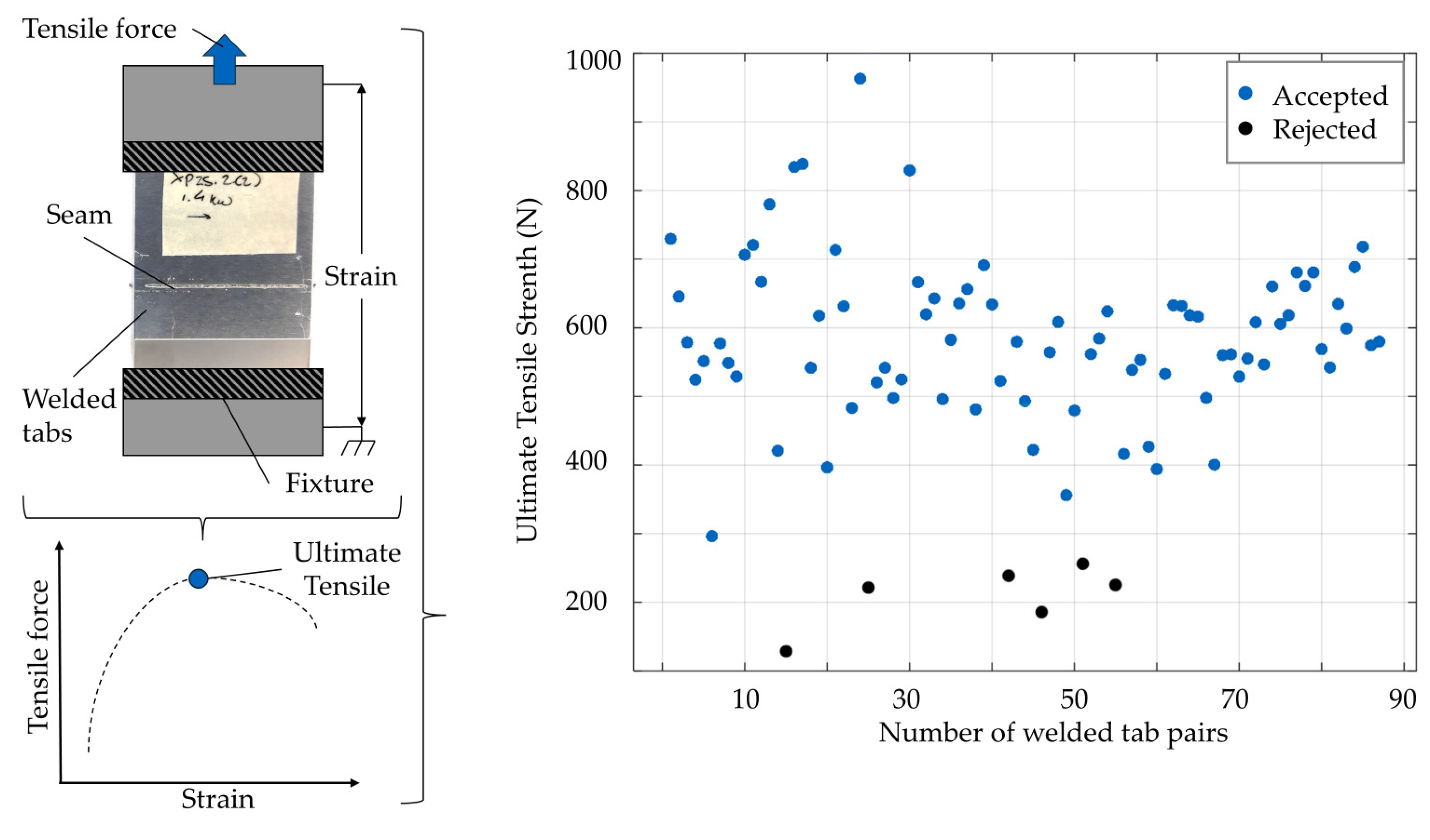
2.3. Mechanical Performance

As with any joint, battery assembly joints must provide satisfactory strength and fatigue performance (Figure 8). This is particularly challenging with the IMCs discussed in the previous section, which are notorious for their poor mechanical performance (high microhardness of IMCs results in brittleness and low mechanical strength) [34]. In [35], the authors showed that while the ultimate shear strength of the Cu–Al ball bond does not decrease with increasing intermetallic formation, fatigue tests (cycle shear tests) showed that the intermetallic interface is responsible for the ultimate failure. Thus, during cyclic loading, cracks are easily deflected into the formed IMC interface, leading to the early failure of the bonds due to their brittle nature. Closer to a battery assembly scenario in [36], the authors showed that IMC formation can be suppressed by increasing the LW speed of Al–Cu sheets, resulting in mechanically stronger welds. In addition, in LW, spatial beam oscillation, weld shape, and the number of welds also seem to affect the maximum mechanical breaking load [24]. Another noteworthy mechanical challenge relates to UW, where process vibrations can cause a joint made on the same workpiece to fail when a new one is made [20]. Finally, as a side note for the case of WB, as the reader can see, the joints cannot be used as structural ones, as the mechanical strength of the joints is very high, and therefore additional supports for clamping the batteries are mandatory [11].

2.4. Material and Metalurgical Aspects

As mentioned above, battery assembly involves the joining of dissimilar materials. This poses a number of challenges, particularly with regard to the melting process, which suffers from the formation of intermetallic phases (Figure 9), which are extremely brittle [34]. In LW, more defects such as porosity, hot cracking and corrosion have been reported despite efforts to optimise the process [20]. On the other hand, the RSW process has been optimised for the brazing of Al–Cu (Al liquid, Cu solid), which has extremely minimised the thickness of the intermetallic layer [37]. While UW does not reach melting temperatures, the Al2Cu intermetallic phase has been observed in the welding of Al–Cu joints, which seems to increase with increasing welding time. However, this occurs at a limited layer thickness compared to most LW or RSW cases [38]. To this end, coatings and interlayers are being investigated to tailor and improve the joint properties [39]. In addition to material dissimilarity, challenges for LW arise from the absorptivity of most of the non-ferrous materials used. These challenges relate to the use of infrared laser light as mentioned in previous sections. Coating and surface oxidation are other issues that add to the difficulties. Finally, battery assembly involves the welding of parts with multiple layers and/or different thicknesses, which presents challenges such as unbonded interface parts for methods such as UW [40].

3. Quality Assurance Approaches for Battery Welding Applications

3.1. State of Practice

The quality assurance of joints in battery module assembly mainly concerns electrical resistance testing. In most applications, this is done as part of the end-of-line test. Automation is used to measure multiple points simultaneously, using dedicated modules that can perform multiple resistance measurements using four-wire probes, multiplexers, and high-precision multimeters [42,43]. Of course, end-of-line testing can also include the visual inspection of joints using a camera-based system, but this is limited to providing information about surface defects and features. Finally, there are some more advanced solutions that relate to specific welding processes. For example, a system developed and demonstrated for RSW uses active lock-in thermography, which consists of applying a periodic electrical signal to the battery and simultaneously monitoring the resulting temperature change with a synchronised thermal camera. The electrical signal is applied by an external power supply or the source load during the end-of-line testing. A computer takes multiple infrared images and applies a processing algorithm to create a surface map and identify hotspots. The system can detect various defects such as cold welds, weld cracks, incomplete penetration, and weld spatter [44]. Another system, which is a complete turnkey solution for LW busbar welding, integrates a pyrometer-enabled system that can provide process monitoring and control functions [45]. For WB applications, many systems are equipped with a pull test function that can be applied in situ. Typically, a predefined pull is applied immediately after a joint is made to identify weak joints [46].
Of course, beyond these dedicated applications, as with any welding application, destructive and non-destructive tests are performed on specimens to define the chemical, mechanical, and metallurgical properties of a specimen, as well as to identify defects located within the weld bead, such as internal cracks, porosity, incomplete fusion and poor penetration, slag inclusion and, in general, internal geometric features. These tests are carried out in the industry for the qualification of a welding process, welder, or remote welding operator and as part of quality control programs and standards of organisations such as the American Welding Society, the European Welding Federation, and others [47]. For special variants, such as WB, patented tests have also been developed to identify faults that cannot be detected by classic tests when the process parameters are varied [48].
Returning to the end-of-line testing approaches, their main disadvantage is obviously that they require an additional step to implement, which adds time to the battery assembly production. In addition, in most cases, these approaches require physical access to the joints, which depends on the design of the battery pack or module. Another problem can be identified for electrical resistance measurements. This concerns the wear of the measurement equipment, as contact is required. Sample-based destructive and non-destructive testing is performed offline. This means that the decision on the quality of the joint is not immediate. In addition, because decisions are based on statistics, bad joints may end up on the final modules, and good modules may be marked for rejection or rework even though they do not contain defective joints, thus increasing the overall production costs.

3.2. Monitoring and Quality Assessment

3.2.1. Laser Welding

Approaches to on-line quality assessment in battery welding applications are rather limited. In [49], a thermal camera attached to a robotic LW system monitored the welding of dissimilar overlapping Al–Cu pouch cell tabs (Figure 10). The authors developed two simple but accurate machine learning (ML) models, a neural network and a support vector machine model, using only three features. Despite the low dimensionality of the data, the two models were able to predict immediately after welding whether the electrical resistance and mechanical strength of each joint were within a certain range. In other words, they were able to classify whether a joint was satisfactory from a mechanical and electrical point of view.
A more conventional approach in terms of LW is presented in [50] and concerns the gap between the parts and the weld penetration in the welding of battery tabs (Ni-plated Cu 300 µm to Ni-plated steel 300 µm). This time a photodiode is placed in the optical path of the laser, providing information on the radiation emitted from the plasma plume and metal vapour, the processing zone and the reflected laser light. Several experiments were designed, including joints with part-to-part gap variations and/or excessive weld penetration. Three quality classes were used to characterise these welds: sound weld, no joint, and overpenetration. While no model was developed to classify the photodiode signals, the feasibility for a supervised ML model was discussed. For example, the step change in the plasma signal and the increase in the scatter levels of the remaining sensor signals were associated with part-to-part variation and overpenetration, respectively.
In general, vision monitoring of LW in terms of weld penetration has been extensively investigated in several studies, not only in the context of battery module welding, but also in the context of dissimilar metal welding. Deep learning (DL) has been used to estimate the penetration depth in the case of Al–Cu laser-welded overlap joints [51]. A convolutional neural network fed with coaxial weld pool images and a photodiode signal was used as a regressor, achieving an exceptional mean average error over different power and welding speed levels in predicting the penetration depth. Using optical coherence tomography (OCT), the authors in [52] were able to achieve in-process monitoring of weld penetration depth during the remote LW of thin foil Al and Cu components used as tab connectors for automotive batteries. Too large a penetration depth or too small may indicate heat damage to the battery cell or no electrical connection, respectively. A non-coaxially mounted photodiode was used in [53] to monitor an Al–Cu laser overlap weld, but that time in order to classify the penetration mode into three levels, as previously. A recent study [54] investigated the effectiveness of five vision sensors, namely four photodiodes to detect the light emitted by the plasma, the hot weld zone, and the back reflection of the laser (off-axis & coaxial), and a spectrometer for the case of LW Ni-plated steel over Cu busbar. The back reflection signals were good indicators for identifying process drift and variation. This was evident as the corresponding ML models were able to classify the two defocusing modes, the presence of a gap between the sheets, and the case of a good weld with very high accuracy using only three features from a single time series signal.
As far as LW applications are concerned, the majority of studies focus on the assessment of dimensional features such as penetration depth, mainly using vision sensors such as photodiodes, cameras, and spectrometers. Very few of them, at least in the case of battery module welding, focus on the assessment of mechanical and electrical quality or even on the identification of specific defects [55]. However, the same cannot be said for another laser LW application in electromobility, hairpin welding. In [56], OCT is used to generate the surface topographical information of the weld bead. Correlations between electrical resistance and different types of misalignment were obtained with correlation coefficients of up to 0.75. Similarly, in [57], a number of defects such as holes, spatters, undercuts, and other irregularities as well as the electrical resistance were classified using different feature extraction algorithms and ML\DL models based on colour images of the welds taken from three different views of the hairpin (top, front, and side). In both studies, the external geometrical features of the joints were used to predict the electrical resistance.
Although not directly related to joint quality, the monitoring of the laser welding process for dissimilar materials has also been investigated in relation to the formation of IMCs. Laser-induced fluorescence has been used to study laser spot welding of 200 μm thick Cu and Al foils [58]. In particular, the authors were able to detect Cu melting quite early, even under low power conditions, thus allowing the monitoring of the formation and evolution of IMCs, which is critical for electrical and mechanical performance.
Quality assurance approaches for battery LW applications all seem to be based on monitoring systems that can be easily integrated into a real production scenario with little or no compromise to their real-time performance. This is particularly true for those approaches that use simple sensing elements such as photodiodes.

3.2.2. Ultrasonic Welding

While LW has many advantages for battery welding applications, UW offers a major advantage in that the metals involved are not melted. However, as with any welding process, in addition to a good process design, monitoring is required to capture any process variability. In a not so recent monitoring approach [59], the authors developed custom thin film microsensors to investigate the heat generation during UW of a three-layer tab on a Cu busbar. These sensors provided information to validate the existence of three distinct process stages of frictional heating, plastic working, and diffusion bonding, thus demonstrating the potential for the robust process control of UW. Since vibrations are the more recognisable feature of the process, the authors in [60] measured the UW of Cu sheets parallel to the direction of vibration using two laser vibrometers pointing at the horn and anvil. The monitoring setup was supported by a high-speed camera, which framed the entire system (welding machine and workpiece) and allowed the monitoring of its oscillations through the calculation of the optical flow. In addition, three thermocouples were placed on the workpiece surfaces and interfaces to measure the corresponding temperatures. The laser vibrometer data were correlated with the thermal measurements and the T-peel and micrograph data of joints made using different process parameters (amplitude, rolling direction). The monitoring of the anvil proved to be the more suitable approach to provide the data required to classify different joints. On the other hand, the input parameter signals recorded by the welding machine only occasionally provided the necessary information to identify process changes. Regarding the last point, the authors in [61] pointed out the same limitation, which eventually led them to use, in addition to the power input signal, the frequency of the piezo-ceramic module signals and the displacement between the anvil and the horn using a linear variable differential transformer (LVDT) sensor. The proposed methodology is based on an algorithm that integrates univariate Shewhart-type control charts and the Mahalanobis distance. After tuning, the algorithm, using six features extracted from the aforementioned signals, derived the control limits and validated the corresponding system in real time. For a battery welding scenario, this methodology achieved near perfect classification performance of good versus bad welds (cold welds) in terms of both Type I (false alarm) and Type II (misdetection) errors.
In addition to conventional monitoring approaches, ML approaches have also been carried out in the literature, aiming at the evaluation of specific quality indicators, rather than simply establishing a relationship with the monitored signals or extracting some kind of control thresholds. In [62], the authors propose a physics-informed ensemble learning framework for the online prediction of joint strength. This framework models the large-scale influence of physical factors and the small-scale natural variability as a global trend and residual, respectively. Using discrete wavelet transform, features were extracted from the four signals acquired by using an acoustic emission module (on the anvil), a power sensor, a microphone, and a LVDT sensor. These features, together with the process parameters involved and the measured machine tool condition, were used to improve the prediction performance of the joint strength for two different case studies in which the machine tool condition and process parameters varied. Similarly, but this time using two laser vibrometers to measure horn and anvil vibration and an LVDT sensor to measure the lateral movement between the horn and anvil, the authors monitored the UW of overlapped Cu sheets [63]. Several reference welds were made, along with welds where the materials and process were deliberately sub-optimal, to generate the training data. Using the features extracted from the power and height curve, the authors developed an exponential Gaussian regression model to predict the weld strength.
Although the studies on UW are much fewer than those carried out for LW, they tend to focus on joint characteristics that are more related to those discussed in Section 2 and to battery welding applications. Laser vibrometers for measuring the vibration of the horn and anvil and LVDT sensors for measuring their relative position appear to be the most commonly used sensors to provide the data required to predict joint strength.
For the sake of completeness, it is worth mentioning that although WB shares some basic characteristics with UW, it has not been researched in the context of battery assembly applications [11]. However, this has not been the case for microelectronics and power electronics, where in situ diagnostics have long been established. For example, in [64], the authors attempted to correlate high-frequency tool vibration and bonding pressure with average bond strength using wavelet decomposition, similar to previous studies of UW. Similarly, in a more recent study [65], the authors used time–frequency analysis and a neural network to classify and identify failed bonds in the case of integrated circuit packaging.

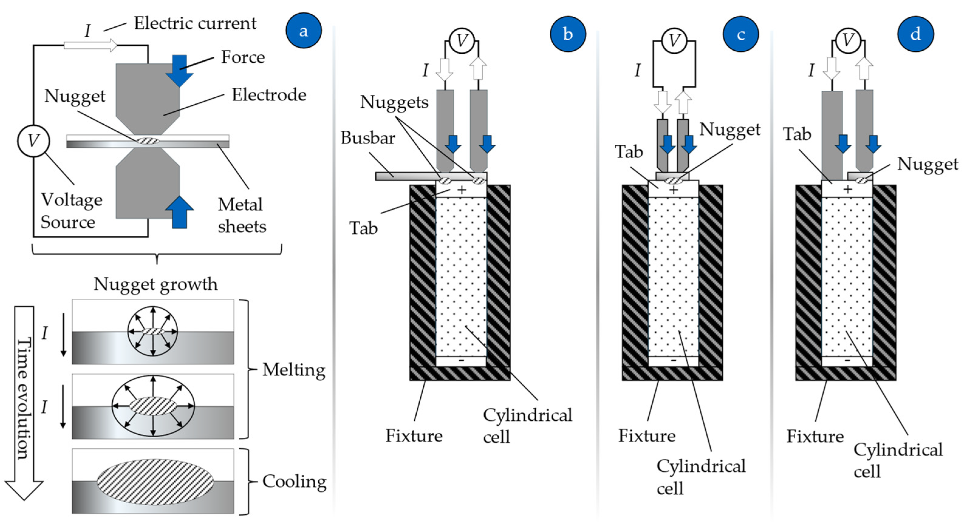
3.2.3. Resistance Spot Welding

Finally, the authors identified a limited number of studies on on-line quality assurance approaches for what is probably the most cost-effective and one of the most easily adaptable welding processes for low-volume production, RSW. Micro-series RSW of thin steel sheets is monitored by a novel dual accelerometer system mounted on top of each electrode holder [66]. The analysis of the monitoring data showed that the movement of the electrodes reflected thermomechanical phenomena during the process, such as unbalanced spot heating. Following this, a more advanced approach in [67] presents a ML-based quality prediction model for the case of single-sided double-jointed RSW of overlapped Ni–Cu sheets. By using a constant voltage controller and considering the input process parameters as predictors and the nugget diameters and tensile shear load of the joints as targets, the authors developed a multi-output regression model. Although the amount of evaluation data was limited, the relative errors of the model were less than 4% for all predicted values.

3.3. Process Optimisation

Process optimisation is by far the most researched area of quality assurance for battery welding applications. Most of the studies have been carried out either as pure experimental investigations to find the process parameters that optimise one or more KPIs of a joint, suppress defects, or validate a process model.

3.3.1. Laser Welding

In the case of LW, welding speed and laser power are probably the most common process parameters that have been optimised in different applications. In [24], for example, the authors included, in addition to the previously mentioned process parameters, the circular wobble parameters of the laser and the double seam design to study the welding of thin Al–Cu overlapped sheets. In addition to determining the optimal process power and welding speed levels, the authors showed that the electrical resistance factor, and thus the electrical resistance of the joints, was slightly lower for the double seam case, but not twice as low. Also, the electrical resistance of the joints was not affected by the different wobble parameters. The mechanical strength increased as the penetration depth decreased, but again only by 10–20% for the double seam. The wobble amplitude was related to the aspect ratio of the joints, while the microhardness showed a slight increase in the fusion zone compared to the base metal. In a similar study, two different spot diameters at different power and welding speeds were investigated for the case of welding Cu to Al thin sheets [68]. The results showed that the small spot size minimised the formation of Cu-rich IMCs and provided better control of the penetration depth and mixing of the base materials. Low electrical resistance was achieved at low penetration depths and large weld bead widths. This conclusion was also reached in [28], where the authors found that a thin intermetallic layer ensures low values of electrical resistance and high mechanical strength by studying the LW of Al on Cu sheets. Increased welding speed has been identified as the factor that suppresses the formation of IMCs, which cause high electrical resistivity, reduced mechanical strength, and high brittleness [36]. A more recent and unusual study is presented in [69]. The authors investigated the effect of nickel plating thickness on the copper-to-steel welding of busbars to cylindrical cell tabs. The experimental campaign included two laser sources, a single mode and a beam shaping one. In the case of the former, the width of the weld bead is influenced by the thickness of the plating, while in the case of the latter, the fluence actually seems to affect the shape of the weld bead. Finally, as blue laser technology is gaining ground in battery assembly applications, ref. [70], the authors conducted an experimental study to compare the experimental results for the mechanical and metallurgical behaviour of lap joints made using a blue and an infrared laser system. The results of the elemental and microhardness analysis showed that in the case of the blue laser, the penetration depth could be regulated, and thus, the joint strength could be predicted. On the other hand, the infrared laser could not offer the same degree of control, as the joints produced were either not fused or had cracks and excessive porosity.
There are fewer modelling approaches for battery LW applications or for dissimilar metal welding. In a recent approach [71] by combining computational fluid dynamics and finite element analysis process simulation in the T2T welding of thin Cu sheets, the authors were able to predict the weld bead dimension with high accuracy and also predict the mechanical properties such as the failure point and the force–displacement curves of shear tests. To investigate the effect of joint size and shape on the electrical resistance of the joint, the authors in [72] developed a multi-physics simulation model. Although the model inputs were not linked to the process parameters, good accuracy was achieved in the predicted values compared to the measured Cu–steel laser welded joints. Similarly, in [73], this time using a simpler approach to modelling a single and a double joint, the authors were able to see that increasing the seam spacing of a double joint increased the electrical conductivity. On the other hand, a simple increase in contact area was found to actually decrease conductivity.
The majority of process optimisation studies, which are quite numerous, more or less justify the same trends. For LW in battery welding applications involving dissimilar materials, low penetration depth is generally preferred as it limits the size of the intermetallic layer, which is typically associated with high electrical and mechanical performance. In addition, another common point was that joints with poor mechanical strength also exhibited poor electrical conductivity and vice versa. Until recently, modelling approaches appeared to be few and far between, and in most cases did not model the actual process but the joint itself. However, insights into weld design have shown that shape is one of the most important parameters for joint performance.

3.3.2. Ultrasonic Welding

With regard to UW, the available studies mainly investigate, optimise, and model the mechanical properties of the joints. For example, in [74], the effects of vibration amplitude, welding pressure, and welding time were investigated to produce a satisfactory Al–Cu T2B joint. The lap shear strength of the joints was most affected by variations in welding pressure and time. Longer welding times and high to moderate pressures (sufficient to immerse the sonotrode) resulted in joints with high shear strength. On the other hand, the T-peel strength was influenced by all three parameters, but mainly by time. Following a pure optimisation approach in [75], the authors used a ML-based response surface methodology to optimise the lap shear and peel strength of joints made using overlapped Cu sheets. It was shown that the shear strength has two global maxima, one for low vibration amplitude and long welding time and one for high vibration amplitude and short welding time. On the contrary, the peel strength was much lower than the shear strength and presented a single global maximum point for a modest welding duration and a small vibration amplitude. In addition, the strength calculated for the joint surface showed a clear threshold at which the joints changed from cold to sound. In the same vein, the authors in [76] investigated two different thin sheet material combinations in an overlapped configuration. The response surface plots for the case of Al–Cu showed that the lap shear and T-peel strength decreased as the welding time or amplitude increased. In the case of the Cu–steel combination, the lap shear strength decreased while the T-peel strength increased for higher limits of the input parameters. In addition to the search for optimisation of the lap shear and T-peel strength in [77], the authors also investigated the effects of the process parameters on the electrical resistance of the joints. By studying three different levels of welding pressure, time, and vibration amplitude, the results showed that, apart from the shear strength, which showed a monotonic behaviour, the peel strength and the electrical resistance did not show a monotonic behaviour. Thus, a single set of parameters could be extracted to maximise both weld strength and conductivity metrics. A recent work, which escapes the pattern of the previous studies, has been carried out in [78], with the aim of analysing the improvements brought by the adoption of the Ni layer between an aluminium and copper tab. According to the authors, UW Al–Cu joints experience degradation due to thermal ageing, the growth of IMCs layers, and the development of Kirkendall voids. The introduction of the Ni layer suppressed the growth of IMCs and ultimately improved the mechanical stability of these joints.
As with LW, there are few process modelling studies for UW. A novel metallo-thermo-mechanical coupled model was developed to investigate the microstructural evolution of an UW Cu tab to Ni-plated busbar [79]. The 3D finite element model showed that prolonged welding time can cause severe plastic deformation, dynamic recrystallisation, and grain growth. Validation runs confirmed the grain distribution and microhardness predicted by the thermomechanical solution’s distributions. Another modelling approach focused on the effects of longitudinal and bending vibrations of the battery tab during UW [80]. By modelling the battery tab as a thin beam undergoing longitudinal and flexural vibration during the UW of a thin battery tab to a busbar, the authors found that high stresses can be developed, which in turn can develop into fractures if the natural frequency of the tab is similar to the weld frequency. In addition, as in the LW-related studies, the modelling of joints was carried out for the actual joint itself, without considering the welding process. For example, the authors in [81] modelled the fatigue life of joints based on the measured electrical resistance, while in [26], the electrical resistance of joints was modelled and used to investigate their thermal behaviour under different electrical current values.
To this end, studies of UW for battery assembly have focused on investigating and optimising two key performance indicators, namely the lap shear and T-peel strength of the joints. This has been achieved by varying the welding pressure, time, and amplitude, with the latter two receiving the most attention. For the modelling approaches, no trend can be identified as there are very few studies, but it can be said that the existing ones focus on allowing the investigation of dynamic phenomena such as microstructural evolution and fracture evolution due to vibration. In contrast to LW, there is a lack of studies on the optimisation of electrical resistance.
Again, the applications to WB optimisation, as in the area of monitoring and quality assessment, are quite limited. A more recent study [82] examines the bonding of aluminium wires to the nickel-plated steel substrates of cylindrical cells. Among the many findings, the increased process variability in the resulting shear strength of samples produced using the same nominal process parameters suggests a point for further investigation.

3.3.3. Resistance Spot Welding

For RSW, process optimisation has been carried out in various ways, mainly for the single-sided parallel electrode variant. This type of small-scale RSW differs from the classical process in that the joining mechanism cannot be precisely identified due to the extremely short processing times. Very few studies have been carried out on RSW in terms of process investigation and optimisation. In particular, those that have been found either include process optimisation as a side research task or focus on modelling of some aspects of the process. In [67], as mentioned above, the authors trained a ML model to predict the nugget diameters and the tensile shear loads of the joints. Later, they used this model to identify the optimal process parameters and maximise the tensile shear load of the joints or select the right parameters to achieve a given value. According to [83], the welding current was found to have the greatest effect on the joint strength of thin Ni tabs welded to Hi-Lumin cylindrical cell terminals, followed by welding time. No IMCs were formed using the optimised process parameter set. In addition, the authors evaluated the effect of weld design (number of spots) on joint strength. The results showed that four nuggets instead of two resulted in almost twice the strength of the joint.
A parametric study of the welding of cylindrical Hilumin battery cells to thin sheet connectors was also carried out [84]. The authors investigated the effects of various process parameters such as tip geometry, connector strip material and shape, maximum supply voltage, welding time and force, and the distance between two electrodes. This was performed for two different configurations, one concerning the welding of the thin strip to the negative electrode and one to the positive electrode. A sequential mechanical-electrical-thermal model was validated via experiments and used to simulate the deformation, welding current distribution, and temperature distribution on the workpiece in order to find the optimum parameters. Among the results, the authors found that a modest amount of force is most desirable to avoid spatter, poor weld joints, or severe deformation of the materials. Welding time and voltage have similar effects such as excessive heat generation, the creation of burn marks, and deformation of the workpieces. In a similar study [85], the authors investigated the effects of certain RSW parameters, namely the welding position, the welding position sequence, and the slot geometry of a nickel conductor. It was shown that the slot geometry affected the current flow, the different positions caused structural deformations, and the different welding sequences produced joints of different overall quality.
Studies concerning the optimisation of RSW are probably the fewest in number compared to ultrasonic and laser welding and they are limited to process modelling and cases of welding thin metal strips to the terminals of cylindrical cells.

4. Conclusions and Outlook

4.1. Conclusions

In the first part of this state-of-the-art review, the authors took the opportunity to identify the main KPIs used to evaluate tab-to-busbar connections and the challenges associated with them in EV battery assembly applications. Low electrical resistance was identified by the majority of studies as one of the most important factors that could, to some extent, determine the efficiency of the powertrain. Among the many drawbacks that high electrical resistance can bring, inconsistency is the most important in this type of application. The interconnected architecture of the battery pack means that even a single faulty or out-of-spec joint can affect the performance and operation of the entire battery pack. Another challenge, particularly in fusion welding applications, is the joining of non-ferrous dissimilar materials, which promotes the formation of IMCs. These are responsible not only for high electrical resistance, but also for making the joint brittle, of low strength, and susceptible to fatigue. In addition, process design is becoming more challenging, particularly for LW, which, although it appears in the literature to offer the most advantages over other welding methods, requires a high level of expertise as most systems are based on infrared lasers, which suffer from low absorption. Despite these challenges, from a practical point of view, LW still seems to be the preferred process for assembling battery modules and packs, as it does not require two-sided access or extremely rigid fixtures like the single-sided versions of UW and RSW, and of course, it offers high processing speeds to keep up with high production rates. Next is WB, a promising technology that has already been used extensively in the microelectronics industry, offering in situ quality assurance by default and fail-safe designs such as fusible joints. However, at the moment, it only seems to work for low current applications, so mostly for battery pack designs using cylindrical cells.
The quality assurance for battery welding applications is still in its infancy. Commercial solutions exist, but dedicated solutions are based on end-of-line approaches, while online solutions tend to address the generic quality issues of a specific welding process. This means that, on the one hand, there may be accessibility issues as the testing is performed on already assembled modules or packs, and on the other hand, key performance indicators for battery welding applications, such as electrical and fatigue performance of the joints, are not served.
In terms of state-of-the-art approaches, LW is by far one of the most researched welding methods, with UW and RSW close behind. Quality assessment approaches, and in particular those that have been demonstrated to be on-line, are based on a data-driven modelling approach. For LW, as expected, most of them are based on vision monitoring to predict penetration depth. For UW, laser vibrometers and LVDT sensors have mainly been used to predict joint strength, while for RSW, no general trend can be extracted due to the limited number of studies available. In the same vein, for WB, no firm conclusions can be drawn as the available literature is quite limited in terms of battery assembly applications.
Process optimisation, as another means of quality assurance, probably involves a greater number of studies as it is the first step in investigating the process window and characteristics for a new application. For LW, this was mainly performed to achieve a low penetration depth, as this was associated with both good mechanical and electrical performance, but generally having the geometrical features of the weld bead. In the case of UW, however, optimising the mechanical strength has been the average trend.
Although there have been individual studies on the electrical performance of joints, the majority of them did not prioritise it. This is in contrast to the fact that almost all of them identified electrical resistance as one of the most important performance indicators in the assembly of battery packs. The same goes for the microstructure and the intermetallic phase mixture, which, as mentioned in several studies, plays a crucial role in both electrical and mechanical performance. Finally, another aspect that has not been on the agenda of advanced quality assurance approaches, but has been identified as critical, is the fatigue susceptibility of these types of joints.
The above conclusions have been drawn mainly in the narrow context of battery welding applications involving the joining of battery cell tabs and busbars. However, they may also apply to some extent to other e-mobility joining applications involving dissimilar and non-ferrous materials, such as the welding of hairpin motors [57]. In the case of IMCs, for example, it is a matter of material rather than application. Therefore, the suppression strategies discussed here, specifically for laser welding applications, could be directly applied to these applications. The same applies to the monitoring and quality assessment approaches, which are likely to have already been implemented in other welding applications, at least for the common KPIs, i.e., mechanical and geometrical features and defects [86].
Finally, it is worth mentioning that although industry and academia seem to be in sync, the requirements and achievements of the former do not seem to be directly mentioned in research articles or addressed as specific case studies. Commercial systems seem to be able to address online quality assessment or even in-process control, and on the other hand, research studies propose similar approaches or systems with similar capabilities, thus not adding any value on top.

4.2. Future Directions

In this section, the authors aim to identify the directions and the technological framework within which the scientific community would provide answers to questions that have not yet been fully clarified regarding the quality assurance of welds in battery assembly applications.
At this stage, it is clear that the research findings in the literature on electrical resistance have not yet reached the appropriate level of maturity. This is particularly the case for the quality assessment of LW processes, where available monitoring systems can provide information on weld bead geometry, but do not appear to be able to assess electrical resistance. This is despite the fact that experimental data have been presented to link the two (electrical resistance and weld bead geometry). The same is true in the case of intermetallic phases, the monitoring of which appears to be possible using spectrometers and can thus contribute to a more complete analysis of the weld bead. The authors therefore consider it important for the research community to focus on these directions. With regard to the UW and RSW processes, the same cannot be suggested due to the limited amount of data available.
Furthermore, as mentioned in this study, fatigue is one of the main mechanical performance indicators directly related to the life of joints. However, to the best of the authors’ knowledge, no specific studies have been carried out on the assembly of batteries, but only on the fatigue of joints during the operation of the battery [81]. Given its importance and the fact that fatigue has been thoroughly studied for a number of applications, the authors have identified another gap that needs to be addressed by the scientific community. More specifically, by looking at other applications, predicting fatigue life is possible by monitoring the process directly by using a machine learning model [87] or indirectly by identifying potential failure points such as micro-cracks [88]. Applying these or similar approaches seems to be a matter of setting the right magnitudes and directions for loads and the number of cycles to represent a real-life scenario of a battery back during service.
Another direction for the scientific community is to study the WB process for battery assembly applications, as it seems to have a significant advantage over the other processes. This advantage comes from the fact that WB allows easy assembly and disassembly of the joints [89,90], which in turn means that it can allow the recycling of battery packs and modules at a lower cost, and in general create a realistic circular economy model for this production chain [91]. Thus, WB could even be the first option of battery manufacturers for battery assembly applications, even if the joints produced may lack the electrical and mechanical advantages of LW and, in general, of processes producing larger joints.
Battery welding applications, such as those reviewed in this study, present numerous challenges, so characterising the quality of a joint cannot rely on a single quality indicator, but requires multiple indicators. While this may seem like a simple extension of the systems reviewed here, such as adding another sensor, it requires more than that. This is because weld quality is determined by the internal and external factors of the welding ecosystem and the interactions between them.
The management of this complexity by a single intelligent entity has already been envisaged, and in some cases partially implemented, under the concept of digital twins. In the literature, the adoption of a digital twin framework has enabled uncertainty management for the robust process control of laser additive manufacturing processes [92], while a deep-learning-based digital twin that handles the replication of joint growth and uses this information as feedback for penetration control has been evaluated in the context of gas tungsten arc welding [93]. Based on this, the authors believe that digital twin-based approaches could add significant value to the quality assurance approaches for battery welding applications.

Author Contributions

Conceptualization, P.S.; methodology, P.S. and H.B.; resources, P.S. and H.B.; writing—original draft preparation, H.B. and K.S.; writing—review and editing, P.S.; visualization, H.B. and K.S.; project administration, P.S.; funding acquisition, P.S. All authors have read and agreed to the published version of the manuscript.

Funding

This research received no external funding.

Data Availability Statement

Not applicable.

Acknowledgments

This work has been supported by EIT Manufacturing, under the activity A21122 “ZELD-e: Zero-defect welding for e-mobility”.

Conflicts of Interest

The authors declare no conflicts of interest.

References

  1. Athanasopoulou, L.; Bikas, H.; Papacharalampopoulos, A.; Stavropoulos, P.; Chryssolouris, G. An industry 4.0 approach to electric vehicles. Int. J. Comput. Integr. Manuf. 2023, 36, 334–348. [Google Scholar] [CrossRef]
  2. Trends in Batteries, Global EV Outlook 2023 by IEA. Available online: https://www.iea.org/reports/global-ev-outlook-2023/trends-in-batteries (accessed on 15 January 2024).
  3. Battery European Partnership Association. Available online: https://bepassociation.eu (accessed on 15 January 2024).
  4. Duffner, F.; Wentker, M.; Greenwood, M.; Leker, J. Battery cost modeling: A review and directions for future research. Renew. Sustain. Energy Rev. 2020, 127, 109872. [Google Scholar] [CrossRef]
  5. König, A.; Nicoletti, L.; Schröder, D.; Wolff, S.; Waclaw, A.; Lienkamp, M. An overview of parameter and cost for battery electric vehicles. World Electr. Veh. J. 2021, 12, 21. [Google Scholar] [CrossRef]
  6. Yuan, C.; Deng, Y.; Li, T.; Yang, F. Manufacturing energy analysis of lithium ion battery pack for electric vehicles. CIRP Ann. 2017, 66, 53–56. [Google Scholar] [CrossRef]
  7. Han, X.; Lu, L.; Zheng, Y.; Feng, X.; Li, Z.; Li, J.; Ouyang, M. A review on the key issues of the lithium ion battery degradation among the whole life cycle. ETransportation 2019, 1, 100005. [Google Scholar] [CrossRef]
  8. Kawamoto, R.; Mochizuki, H.; Moriguchi, Y.; Nakano, T.; Motohashi, M.; Sakai, Y.; Inaba, A. Estimation of CO2 emissions of internal combustion engine vehicle and battery electric vehicle using LCA. Sustainability 2019, 11, 2690. [Google Scholar] [CrossRef]
  9. Athanasopoulou, L.; Bikas, H.; Stavropoulos, P. Comparative well-to-wheel emissions assessment of internal combustion engine and battery electric vehicles. Procedia CIRP 2018, 78, 25–30. [Google Scholar] [CrossRef]
  10. EV Battery Production, Building the Battery Pack. Available online: https://www.automotivemanufacturingsolutions.com/ev-battery-production/building-the-battery-pack/41711.article (accessed on 15 January 2024).
  11. Zwicker, M.F.R.; Moghadam, M.; Zhang, W.; Nielsen, C.V. Automotive battery pack manufacturing–a review of battery to tab joining. J. Adv. Join. Process. 2020, 1, 100017. [Google Scholar] [CrossRef]
  12. Grabmann, S.; Kriegler, J.; Harst, F.; Günter, F.J.; Zaeh, M.F. Laser welding of current collector foil stacks in battery production–mechanical properties of joints welded with a green high-power disk laser. Int. J. Adv. Manuf. Technol. 2022, 118, 2571–2586. [Google Scholar] [CrossRef]
  13. Das, A.; Li, D.; Williams, D.; Greenwood, D. Joining technologies for automotive battery systems manufacturing. World Electr. Veh. J. 2018, 9, 22. [Google Scholar] [CrossRef]
  14. Elangovan, S.; Semeer, S.; Prakasan, K. Temperature and stress distribution in ultrasonic metal welding—An FEA-based study. J. Mater. Process. Technol. 2009, 209, 1143–1150. [Google Scholar] [CrossRef]
  15. Das, A.; Masters, I.; Williams, D. Process robustness and strength analysis of multi-layered dissimilar joints using ultrasonic metal welding. Int. J. Adv. Manuf. Technol. 2019, 101, 881–900. [Google Scholar] [CrossRef]
  16. Long, Y.; Twiefel, J.; Wallaschek, J. A review on the mechanisms of ultrasonic wedge-wedge bonding. J. Mater. Process. Technol. 2017, 245, 241–258. [Google Scholar] [CrossRef]
  17. Zhang, C.; Li, H.; Liu, Q.; Huang, C.; Zhou, K. Ultrasonic Welding of Aluminum to Steel: A Review. Metals 2022, 13, 29. [Google Scholar] [CrossRef]
  18. Kang, H.; Sharma, A.; Jung, J.P. Recent progress in transient liquid phase and wire bonding technologies for power electronics. Metals 2020, 10, 934. [Google Scholar] [CrossRef]
  19. Stavropoulos, P.; Sabatakakis, K.; Papacharalampopoulos, A.; Mourtzis, D. Infrared (IR) quality assessment of robotized resistance spot welding based on machine learning. Int. J. Adv. Manuf. Technol. 2022, 119, 1785–1806. [Google Scholar] [CrossRef]
  20. Brand, M.J.; Schmidt, P.A.; Zaeh, M.F.; Jossen, A. Welding techniques for battery cells and resulting electrical contact resistances. J. Energy Storage 2015, 1, 7–14. [Google Scholar] [CrossRef]
  21. Papacharalampopoulos, A.; Stavropoulos, P.; Stavridis, J. Adaptive control of thermal processes: Laser welding and additive manufacturing paradigms. Procedia CIRP 2018, 67, 233–237. [Google Scholar] [CrossRef]
  22. Sadeghian, A.; Iqbal, N. A review on dissimilar laser welding of steel-copper, steel-aluminum, aluminum-copper, and steel-nickel for electric vehicle battery manufacturing. Opt. Laser Technol. 2022, 146, 107595. [Google Scholar] [CrossRef]
  23. Ascari, A.; Fortunato, A. Laser dissimilar welding of highly reflective materials for E-Mobility applications. Join. Process. Dissimilar Adv. Mater. 2022, 579–645. [Google Scholar] [CrossRef]
  24. Dimatteo, V.; Ascari, A.; Fortunato, A. Continuous laser welding with spatial beam oscillation of dissimilar thin sheet materials (Al–Cu and Cu–Al): Process optimization and characterization. J. Manuf. Process. 2019, 44, 158–165. [Google Scholar] [CrossRef]
  25. Prieto, C.; Vaamonde, E.; Diego-Vallejo, D.; Jimenez, J.; Urbach, B.; Vidne, Y.; Shekel, E. Dynamic laser beam shaping for laser aluminium welding in e-mobility applications. Procedia CIRP 2020, 94, 596–600. [Google Scholar] [CrossRef]
  26. Das, A.; Ashwin, T.R.; Barai, A. Modelling and characterisation of ultrasonic joints for Li-ion batteries to evaluate the impact on electrical resistance and temperature raise. J. Energy Storage 2019, 22, 239–248. [Google Scholar] [CrossRef]
  27. Hoekstra, F.S.; Bergveld, H.J.; Donkers, M.C.F. Optimal Control of Active Cell Balancing: Extending the Range and Useful Lifetime of a Battery Pack. IEEE Trans. Control Syst. Technol. 2022, 30, 2759–2766. [Google Scholar] [CrossRef]
  28. Solchenbach, T.; Plapper, P.; Cai, W. Electrical performance of laser braze-welded aluminum–copper interconnects. J. Manuf. Process. 2014, 16, 183–189. [Google Scholar] [CrossRef]
  29. Huang, W.; Wang, H.; Rinker, T.; Tan, W. Investigation of metal mixing in laser keyhole welding of dissimilar metals. Mater. Des. 2020, 195, 109056. [Google Scholar] [CrossRef]
  30. Mathivanan, K.; Plapper, P. Laser welding of dissimilar copper and aluminum sheets by shaping the laser pulses. Procedia Manuf. 2019, 36, 154–162. [Google Scholar] [CrossRef]
  31. Indhu, R.; Vivek, V.; Sarathkumar, L.; Bharatish, A.; Soundarapandian, S. Overview of laser absorptivity measurement techniques for material processing. Lasers Manuf. Mater. Process. 2018, 5, 458–481. [Google Scholar] [CrossRef]
  32. Bohn, P.; Liebig, G.; Komsiyska, L.; Wittstock, G. Temperature propagation in prismatic lithium-ion-cells after short term thermal stress. J. Power Sources 2016, 313, 30–36. [Google Scholar] [CrossRef]
  33. Das, A.; Li, D.; Williams, D.; Greenwood, D. Weldability and shear strength feasibility study for automotive electric vehicle battery tab interconnects. J. Braz. Soc. Mech. Sci. Eng. 2019, 41, 54. [Google Scholar] [CrossRef]
  34. Kah, P.; Vimalraj, C.; Martikainen, J.; Suoranta, R. Factors influencing Al–Cu weld properties by intermetallic compound formation. Int. J. Mech. Mater. Eng. 2015, 10, 1–13. [Google Scholar] [CrossRef]
  35. Lassnig, A.; Pelzer, R.; Gammer, C.; Khatibi, G. Role of intermetallics on the mechanical fatigue behavior of Cu–Al ball bond interfaces. J. Alloys Compd. 2015, 646, 803–809. [Google Scholar] [CrossRef]
  36. Lee, S.J.; Nakamura, H.; Kawahito, Y.; Katayama, S. Effect of welding speed on microstructural and mechanical properties of laser lap weld joints in dissimilar Al and Cu sheets. Sci. Technol. Weld. Join. 2014, 19, 111–118. [Google Scholar] [CrossRef]
  37. Zare, M.; Pouranvari, M. Metallurgical joining of aluminium and copper using resistance spot welding: Microstructure and mechanical properties. Sci. Technol. Weld. Join. 2021, 26, 461–469. [Google Scholar] [CrossRef]
  38. Liu, J.; Cao, B.; Yang, J. Texture and intermetallic compounds of the Cu/Al dissimilar joints by high power ultrasonic welding. J. Manuf. Process. 2020, 76, 34–45. [Google Scholar] [CrossRef]
  39. Chen, S.; Zhai, Z.; Huang, J.; Zhao, X.; Xiong, J. Interface microstructure and fracture behavior of single/dual-beam laser welded steel-Al dissimilar joint produced with copper interlayer. Int. J. Adv. Manuf. Technol. 2016, 82, 631–643. [Google Scholar] [CrossRef]
  40. Shin, H.S.; de Leon, M. Mechanical performance and electrical resistance of ultrasonic welded multiple Cu-Al layers. J. Mater. Process. Technol. 2017, 241, 141–153. [Google Scholar] [CrossRef]
  41. Ali, S.; Shin, J. In-Depth Characterization of Laser-Welded Aluminum-and-Copper Dissimilar Joint for Electric Vehicle Battery Connections. Materials 2022, 15, 7463. [Google Scholar] [CrossRef] [PubMed]
  42. Measuring Welding Resistance to Improve the Performance of Lithium-Ion Batteries, HIOKI. Available online: https://www.hioki.com/euro-en/industries-solutions/manufacturing/rm3545.html (accessed on 15 January 2024).
  43. Measuring Busbar Weld Resistance in Battery Packs, Tektronix. Available online: https://www.tek.com/en/documents/application-note/measuring-busbar-weld-resistance-in-battery-packs (accessed on 15 January 2024).
  44. Battery Weld Inspection Solutions, moviTHERM. Available online: https://movitherm.com/solutions/quality-inspection/battery-weld-inspection-for-quality-assurance/ (accessed on 15 January 2024).
  45. Busbar Welding Module, Raylase. Available online: https://www.raylase.de/en/products/prefocusing-deflection-units/busbar-welding-module.html (accessed on 15 January 2024).
  46. Hesse in CHARGED: Electric Vehicles Magazine: “A Closer Look at Wire Bonding”, Hesse Mechatronics. Available online: https://www.hesse-mechatronics.com/en/hesse-im-charged-electric-vehicles-magazine-a-closer-look-at-wire-bonding/ (accessed on 20 March 2024).
  47. Stavropoulos, P.; Sabatakakis, K.; Bikas, H.; Papacharalampopoulos, A. Monitoring and Quality Assurance of Laser Welding: From Offline Sample-Based Testing to In-Process Real-Time AI Inference and Digital Twins. In A Guide to Laser Welding, 1st ed.; Pereira, A.B., Marques, E.S.V., da Silva, F.J.G., Eds.; NOVA Science Publishers: Hauppauge, NY, USA, 2024; Volume 1, pp. 329–357. [Google Scholar]
  48. Bondtec Accelerated Mechanical Fatigue Interconnect Testing, F&S Bondtec Austria. Available online: https://www.fsbondtec.at/anwendungen/bamfit-a-rapid-test-for-reliability-of-heavy-wire-bonds/?lang=en (accessed on 20 March 2024).
  49. Stavropoulos, P.; Bikas, H.; Sabatakakis, K.; Theoharatos, C.; Grossi, S. Quality assurance of battery laser welding: A data-driven approach. Procedia CIRP 2022, 111, 784–789. [Google Scholar] [CrossRef]
  50. Chianese, G.; Franciosa, P.; Nolte, J.; Ceglarek, D.; Patalano, S. Characterization of photodiodes for detection of variations in part-to-part gap and weld penetration depth during remote laser welding of copper-to-steel battery tab connectors. J. Manuf. Sci. Eng. 2022, 144, 071004. [Google Scholar] [CrossRef]
  51. Kang, S.; Lee, K.; Kang, M.; Jang, Y.H.; Kim, C. Weld-penetration-depth estimation using deep learning models and multisensor signals in Al/Cu laser overlap welding. Opt. Laser Technol. 2023, 161, 109179. [Google Scholar] [CrossRef]
  52. Sokolov, M.; Franciosa, P.; Sun, T.; Ceglarek, D.; Dimatteo, V.; Ascari, A.; Nagel, F. Applying optical coherence tomography for weld depth monitoring in remote laser welding of automotive battery tab connectors. J. Laser Appl. 2021, 33, 012028. [Google Scholar] [CrossRef]
  53. Lee, K.; Kang, S.; Kang, M.; Yi, S.; Kim, C. Estimation of Al/Cu laser weld penetration in photodiode signals using deep neural network classification. J. Laser Appl. 2021, 33, 042009. [Google Scholar] [CrossRef]
  54. Caprio, L.; Previtali, B.; Demir, A.G. Sensor Selection and Defect Classification via Machine Learning During the Laser Welding of Busbar Connections for High-Performance Battery Pack Production. Lasers Manuf. Mater. Process. 2024, 1–24. [Google Scholar] [CrossRef]
  55. Rohkohl, E.; Kraken, M.; Schönemann, M.; Breuer, A.; Herrmann, C. How to characterize a NDT method for weld inspection in battery cell manufacturing using deep learning. Int. J. Adv. Manuf. Technol. 2022, 119, 4829–4843. [Google Scholar] [CrossRef]
  56. Will, T.; Müller, J.; Müller, R.; Hölbling, C.; Goth, C.; Schmidt, M. Prediction of electrical resistance of laser-welded copper pin-pairs with surface topographical information from inline post-process observation by optical coherence tomography. Int. J. Adv. Manuf. Technol. 2023, 125, 1955–1963. [Google Scholar] [CrossRef]
  57. Mayr, A.; Lutz, B.; Weigelt, M.; Gläßel, T.; Kißkalt, D.; Masuch, M.; Franke, J. Evaluation of machine learning for quality monitoring of laser welding using the example of the contacting of hairpin windings. In Proceedings of the 2018 8th International Electric Drives Production Conference (EDPC), Schweinfurt, Germany, 4–5 December 2018; pp. 1–7. [Google Scholar]
  58. Simonds, B.J.; Tran, B.; Williams, P.A. In situ monitoring of Cu/Al laser welding using laser induced fluorescence. Procedia CIRP 2020, 94, 605–609. [Google Scholar] [CrossRef]
  59. Li, H.; Choi, H.; Ma, C.; Zhao, J.; Jiang, H.; Cai, W.; Li, X. Transient temperature and heat flux measurement in ultrasonic joining of battery tabs using thin-film microsensors. J. Manuf. Sci. Eng. 2013, 135, 051015. [Google Scholar] [CrossRef]
  60. Balz, I.; Abi Raad, E.; Rosenthal, E.; Lohoff, R.; Schiebahn, A.; Reisgen, U.; Vorländer, M. Process monitoring of ultrasonic metal welding of battery tabs using external sensor data. J. Adv. Join. Process. 2020, 1, 100005. [Google Scholar] [CrossRef]
  61. Guo, W.; Shao, C.; Kim, T.H.; Hu, S.J.; Jin, J.J.; Spicer, J.P.; Wang, H. Online process monitoring with near-zero misdetection for ultrasonic welding of lithium-ion batteries: An integration of univariate and multivariate methods. J. Manuf. Syst. 2016, 38, 141–150. [Google Scholar] [CrossRef]
  62. Meng, Y.; Shao, C. Physics-informed ensemble learning for online joint strength prediction in ultrasonic metal welding. Mech. Syst. Signal Process. 2022, 181, 109473. [Google Scholar] [CrossRef]
  63. Müller, F.W.; Schiebahn, A.; Reisgen, U. Quality prediction of disturbed ultrasonic metal welds. J. Adv. Join. Process. 2022, 5, 100086. [Google Scholar] [CrossRef]
  64. Han, L.; Gao, R.; Zhong, J.; Li, H. Wire bonding dynamics monitoring by wavelet analysis. Sens. Actuators A Phys. 2007, 137, 41–50. [Google Scholar] [CrossRef]
  65. Feng, W.; Chen, X.; Wang, C.; Shi, Y. Application research on the time–frequency analysis method in the quality detection of ultrasonic wire bonding. Int. J. Distrib. Sens. Netw. 2021, 17, 15501477211018346. [Google Scholar] [CrossRef]
  66. Lin, H.J.; Chang, H.S. In-process monitoring of micro series spot welding using dual accelerometer system. Weld. World 2019, 63, 1641–1654. [Google Scholar] [CrossRef]
  67. He, Y.; Yang, K.; Wang, X.; Huang, H.; Chen, J. Quality Prediction and Parameter Optimisation of Resistance Spot Welding Using Machine Learning. Appl. Sci. 2022, 12, 9625. [Google Scholar] [CrossRef]
  68. Dimatteo, V.; Ascari, A.; Liverani, E.; Fortunato, A. Experimental investigation on the effect of spot diameter on continuous-wave laser welding of copper and aluminum thin sheets for battery manufacturing. Opt. Laser Technol. 2022, 145, 107495. [Google Scholar] [CrossRef]
  69. Francioso, M.; Angeloni, C.; Fortunato, A.; Liverani, E.; Ascari, A. Experimental investigation on the effect of nickel-plating thickness on continuous-wave laser welding of copper and steel tab joints for battery manufacturing. Lasers Manuf. Mater. Process. 2024, 1–18. [Google Scholar] [CrossRef]
  70. Dhara, S.; Finuf, M.; Zediker, M.; Masters, I.; Barai, A.; Das, A. Utilising blue laser over infrared laser to enhance control of penetration depth and weld strength for producing electric vehicle battery interconnects. J. Mater. Process. Technol. 2023, 317, 117989. [Google Scholar] [CrossRef]
  71. Kamat, S.; Cai, W.; Rinker, T.J.; Bracey, J.; Xi, L.; Tan, W. A novel integrated process-performance model for laser welding of multi-layer battery foils and tabs. J. Mater. Process. Technol. 2023, 320, 118121. [Google Scholar] [CrossRef]
  72. Das, A.; Masters, I.; Haney, P. Modelling the impact of laser micro-joint shape and size on resistance and temperature for Electric Vehicle battery joining application. J. Energy Storage 2022, 52, 104868. [Google Scholar] [CrossRef]
  73. Hollatz, S.; Kremer, S.; Ünlübayir, C.; Sauer, D.U.; Olowinsky, A.; Gillner, A. Electrical modelling and investigation of laser beam welded joints for lithium-ion batteries. Batteries 2020, 6, 24. [Google Scholar] [CrossRef]
  74. Dhara, S.; Das, A. Impact of ultrasonic welding on multi-layered Al–Cu joint for electric vehicle battery applications: A layer-wise microstructural analysis. Mater. Sci. Eng. 2020, 791, 139795. [Google Scholar] [CrossRef]
  75. Meng, Y.; Rajagopal, M.; Kuntumalla, G.; Toro, R.; Zhao, H.; Chang, H.C.; Shao, C. Multi-objective optimization of peel and shear strengths in ultrasonic metal welding using machine learning-based response surface methodology. Math. Biosci. Eng. 2020, 17. [Google Scholar] [CrossRef]
  76. Singh, A.R.; Sudarsan, C.; Das, A.; Hazra, S.; Panda, S.K. Process optimization and characterization of ultra-thin dissimilar sheet material joints for battery applications using ultrasonic welding. J. Mater. Eng. Perform. 2022, 31, 4133–4149. [Google Scholar] [CrossRef]
  77. de Leon, M.; Shin, H.S. Prediction of optimum welding parameters for weld-quality characterization in dissimilar ultrasonic-welded Al-to-Cu tabs for Li-ion batteries. Met. Mater. Int. 2023, 29, 1079–1094. [Google Scholar] [CrossRef]
  78. Jeong, J.M.; Kim, D.; Kim, J.; Bang, J.; Jung, S.B.; Kim, M.S. Improving mechanical stability of Al/Cu ultrasonic bonded joint for battery tab by adopting electroplated Ni interlayer. J. Mater. Sci. Mater. Electron. 2024, 35, 308. [Google Scholar] [CrossRef]
  79. Shen, N.; Samanta, A.; Ding, H.; Cai, W.W. Simulating microstructure evolution of ultrasonic welding of battery tabs. Procedia Manuf. 2016, 5, 399–416. [Google Scholar] [CrossRef]
  80. Kang, B.; Cai, W.; Tan, C.A. Dynamic stress analysis of battery tabs under ultrasonic welding. J. Manuf. Sci. Eng. 2014, 136, 041011. [Google Scholar] [CrossRef]
  81. Zhao, N.; Li, W.; Cai, W.W.; Abell, J.A. A fatigue life study of ultrasonically welded lithium-ion battery tab joints based on electrical resistance. J. Manuf. Sci. Eng. 2014, 136, 051003. [Google Scholar] [CrossRef]
  82. Bieliszczuk, K.; Zręda, J.; Chmielewski, T. Selected properties of aluminum ultrasonic wire bonded joints with nickel-plated steel substrate for 18650 cylindrical cells. J. Adv. Join. Process. 2024, 9, 100197. [Google Scholar] [CrossRef]
  83. Kumar, N.; Ramakrishnan, S.M.; Panchapakesan, K.; Subramaniam, D.; Masters, I.; Dowson, M.; Das, A. In-depth evaluation of micro-resistance spot welding for connecting tab to 18,650 Li-ion cells for electric vehicle battery application. Int. J. Adv. Manuf. Technol. 2022, 121, 6581–6597. [Google Scholar] [CrossRef]
  84. Masomtob, M.; Sukondhasingha, R.; Becker, J.; Sauer, D.U. Parametric study of spot welding between Li-ion battery cells and sheet metal connectors. Eng. J. 2017, 21, 457–473. [Google Scholar] [CrossRef]
  85. Phichai, N.; Kaewtatip, P.; Lailuck, V.; Rompho, S.; Masomtob, M. Parametric effects of resistance spot welding between Li-ion cylindrical battery cell and nickel conductor strip. In IOP Conference Series: Materials Science and Engineering; IOP Publishing: Bristol, UK, 2019; Volume 501, p. 012027. [Google Scholar]
  86. Stavropoulos, P.; Sabatakakis, K. Quality Assurance in Resistance Spot Welding: State of Practice, State of the Art, and Prospects. Metals 2024, 14, 185. [Google Scholar] [CrossRef]
  87. Amiri, N.; Farrahi, G.H.; Kashyzadeh, K.R.; Chizari, M. Applications of ultrasonic testing and machine learning methods to predict the static & fatigue behavior of spot-welded joints. J. Manuf. Process. 2020, 52, 26–34. [Google Scholar]
  88. Mypati, O.; Pal, S.K.; Srirangam, P. Tensile and fatigue properties of aluminum and copper micro joints for Li-ion battery pack applications. Forces Mech. 2022, 7, 100101. [Google Scholar] [CrossRef]
  89. Wu, S.; Kaden, N.; Dröder, K. A Systematic Review on Lithium-Ion Battery Disassembly Processes for Efficient Recycling. Batteries 2023, 9, 297. [Google Scholar] [CrossRef]
  90. Schimanek, R.; Bilge, P.; Dietrich, F. Automated remanufacturing of lithium-ion batteries with shear separation, ultrasonic separation, and ultrasonic welding. Procedia CIRP 2023, 116, 227–232. [Google Scholar] [CrossRef]
  91. Panagiotopoulou, V.C.; Paraskevopoulou, A.; Stavropoulos, P. A Modelling-Based Framework for Carbon Emissions Calculation in Additive Manufacturing: A Stereolithography Case Study. Processes 2023, 11, 2574. [Google Scholar] [CrossRef]
  92. Stavropoulos, P.; Papacharalampopoulos, A.; Michail, C.K.; Chryssolouris, G. Robust additive manufacturing performance through a control oriented digital twin. Metals 2021, 11, 708. [Google Scholar] [CrossRef]
  93. Wang, Q.; Jiao, W.; Zhang, Y. Deep learning-empowered digital twin for visualized weld joint growth monitoring and penetration control. J. Manuf. Syst. 2020, 57, 429–439. [Google Scholar] [CrossRef]
Figure 1. Battery demand for EVs by region between 2016 and 2022 [2].
Batteries 10 00146 g001
Figure 2. Current and future direct costs of BEVs and ICEVs [5].
Batteries 10 00146 g002
Figure 3. Battery pack hierarchy and joining requirements (left) and battery cell types and their main components (right) [13].
Batteries 10 00146 g003
Figure 5. Schematic representation of a typical RSW process for joining two thin metal sheets (a), Series configuration RSW of busbar to cylindrical cell tab (b), Parallel gap configuration RSW of busbar to cylindrical cell tab (c), step configuration RSW of busbar to cylindrical cell tab (d).
Batteries 10 00146 g005
Figure 6. Schematic representation of a typical LW process for joining two thin metal sheets (a), LW of two overlapping pouch cell tabs (b), LW of busbars onto prismatic cell tabs (c), LW of a single busbar onto multiple cylindrical cell tabs (d).
Batteries 10 00146 g006
Figure 7. Electrical resistance measurements of laser-welded Al–Cu pouch cell tabs for the assembly of a module across two paths (R1, R2) using four wire measurements (Kelvin probes).
Batteries 10 00146 g007
Figure 8. Ultimate tensile shear strength of laser-welded Al–Cu pouch cell tab samples for the assembly of a module.
Batteries 10 00146 g008
Figure 9. Scanning electron microscopy image of laser-welded Al–Cu thin sheet: crystal structures and intermetallic phases in the different locations A, B, and C of the sectioned seam [41].
Batteries 10 00146 g009
Figure 10. A vision-based monitoring system for the case of battery LW of overlapping Al–Cu pouch cell tabs (left), the fixture for holding the two battery tabs together (up-right), and the infrared features extracted from the captured video (right-down) [49].
Batteries 10 00146 g010
Disclaimer/Publisher’s Note: The statements, opinions and data contained in all publications are solely those of the individual author(s) and contributor(s) and not of MDPI and/or the editor(s). MDPI and/or the editor(s) disclaim responsibility for any injury to people or property resulting from any ideas, methods, instructions or products referred to in the content.

