Article

High-Performance Supercapacitors Based on Graphene/Activated Carbon Hybrid Electrodes Prepared via Dry Processing

by
Shengjun Chen
1,2,*,†,
Wenrui Wang
3,†,
Xinyue Zhang
3 and
Xiaofeng Wang
1
1
Department of Precision Instrument, Tsinghua University, Beijing 100084, China
2
Ningbo CRRC New Energy Technology Co., Ltd., Ningbo 315112, China
3
School of Mechanical Engineering, Nanjing University of Science and Technology, Nanjing 210094, China
*
Author to whom correspondence should be addressed.
Shengjun Chen and Wenrui Wang are co-first authors.
Batteries 2024, 10(6), 195; https://doi.org/10.3390/batteries10060195
Submission received: 20 April 2024 / Revised: 28 May 2024 / Accepted: 28 May 2024 / Published: 3 June 2024

Abstract

:
Graphene has a high specific surface area and high electrical conductivity, and its addition to activated carbon electrodes should theoretically significantly improve the energy storage performance of supercapacitors. Unfortunately, such an ideal outcome is seldom verified in practical commercial supercapacitor design and production. In this paper, the oxygen-containing functional groups in graphene/activated carbon hybrids, which are prone to induce side reactions, are removed in the material synthesis stage by a special process design, and electrodes with high densities and low internal resistances are prepared by a dry process. On this basis, a carbon-coated aluminum foil collector with a full tab structure is designed and assembled with graphene/activated carbon hybrid electrodes to form a commercial supercapacitor in cylindrical configuration. The experimental tests confirmed that such supercapacitors have high capacity density, power density, low internal resistance (about 0.06 mΩ), good high-current charging/discharging characteristics, and a long lifetime, with more than 80% capacity retention after 10 W cycles.

Graphical Abstract

1. Introduction

A supercapacitor fills the gap between batteries and traditional capacitors with its simultaneously superior power density and energy density, and it has a wide range of commercial applications in microgrids [1], electrical equipment, consumer electronics [2], and many other fields. For commercial supercapacitors, the most used electrode material is activated carbon because of its large specific surface area and low cost [3,4]. For academic research, graphene has attracted extensive attention in the field of supercapacitors due to its special two-dimensional material properties [5,6,7,8,9,10]. As an electrode material, graphene has multiple contributions to the energy storage of supercapacitors: firstly, it has a higher specific surface area than traditional activated carbon, providing a richer microscopic interface for energy storage [11]; secondly, it has a good electrochemical activity [12], which can realize a greater energy storage density through the pseudocapacitive effect and other electrochemical reactions [13,14,15,16,17]; and thirdly, it has a good electrical conductivity [18], which reduces the energy loss of the supercapacitor itself. As a result, many researchers have focused on next-generation supercapacitors based on graphene electrodes and successfully fabricated many device prototypes with great performance in the laboratory environment [19,20,21,22].
However, until now, supercapacitors based on graphene electrodes did not make ideal progress in the industry and failed to capture a significant market share [23,24]. This is mainly since some active oxygen-containing functional groups of graphene electrode materials constantly have side reactions which produce gases, resulting in an increasing internal resistance and capacity degradation of supercapacitors on longer time scales [25,26]. Although there has been some research devoted to the removal of these potentially unfavorable oxygen-containing functional groups, successful large-scale applications in the industry have not been realized yet.
To solve the above problems, this paper proposes an easy-to-implement manufacturing method for high-performance graphene/activated carbon hybrid electrodes. High-density hybrid electrodes with good mechanical properties are realized by removing oxygen-containing functional groups and humidity in the electrodes via high-temperature treatment and a dry-film-forming process. Based on this hybrid electrode, improvements have been made in both the surface interface design and full tab [27] design of the collector, realizing a commercial-grade, high-performance supercapacitor that can be mass produced. Detailed charge–discharge cycling test data demonstrate the long-term stability of the performance gain of the proposed hybrid electrode supercapacitor.

2. Materials and Methods

To eliminate the oxygen-containing functional groups on the surface of the porous graphene/activated carbon hybrid material, the hybrid was subjected to high-temperature heat treatment at 850 °C for 2 h in a H2/argon mixed atmosphere (H2 volume ratio of 10%) within a tube furnace. This treatment effectively removed the oxygen-containing functional groups on the surface of the hybrid material. The surface functional group content of porous graphene/activated carbon hybrid materials is typically characterized using the alkaline Boehm titration method. The surface contains less than 0.1 meq/g of oxygen-containing functional groups, significantly below industry standards. This is expected to enhance the pressure resistance, lifespan, and safety of electrode materials.
Through the above dry method electrode manufacturing technique, we can prepare electrode sheets with a thickness of 140–150 μM. Using a laser slitting machine to cut the electrode plates, the electrode plate size is 75 × 37 mm, and the battery cells are stacked using opposite side electrode tabs. The preparation environment is controlled to a humidity of dew point temperature of −45 °C and baking conditions of 120 °C for 12 h under a vacuum degree of ≤−90 Kpa with nitrogen replenishment. The moisture content in the final electrode is maintained below 200 ppm. The battery cells are stacked in pairs, with an electrolyte injection ratio of 1:1 (electrolyte/cell mass). Meanwhile, the electrolyte used is 1 mol/L tetrafluoroborate spirocyclic quaternary ammonium salt (SBP-BF4)/acetonitrile (AN).

3. Results

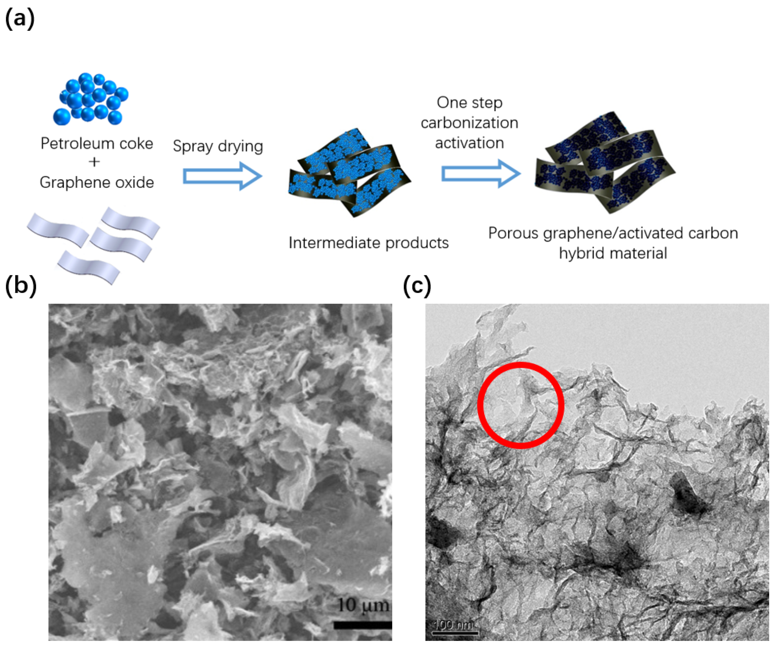
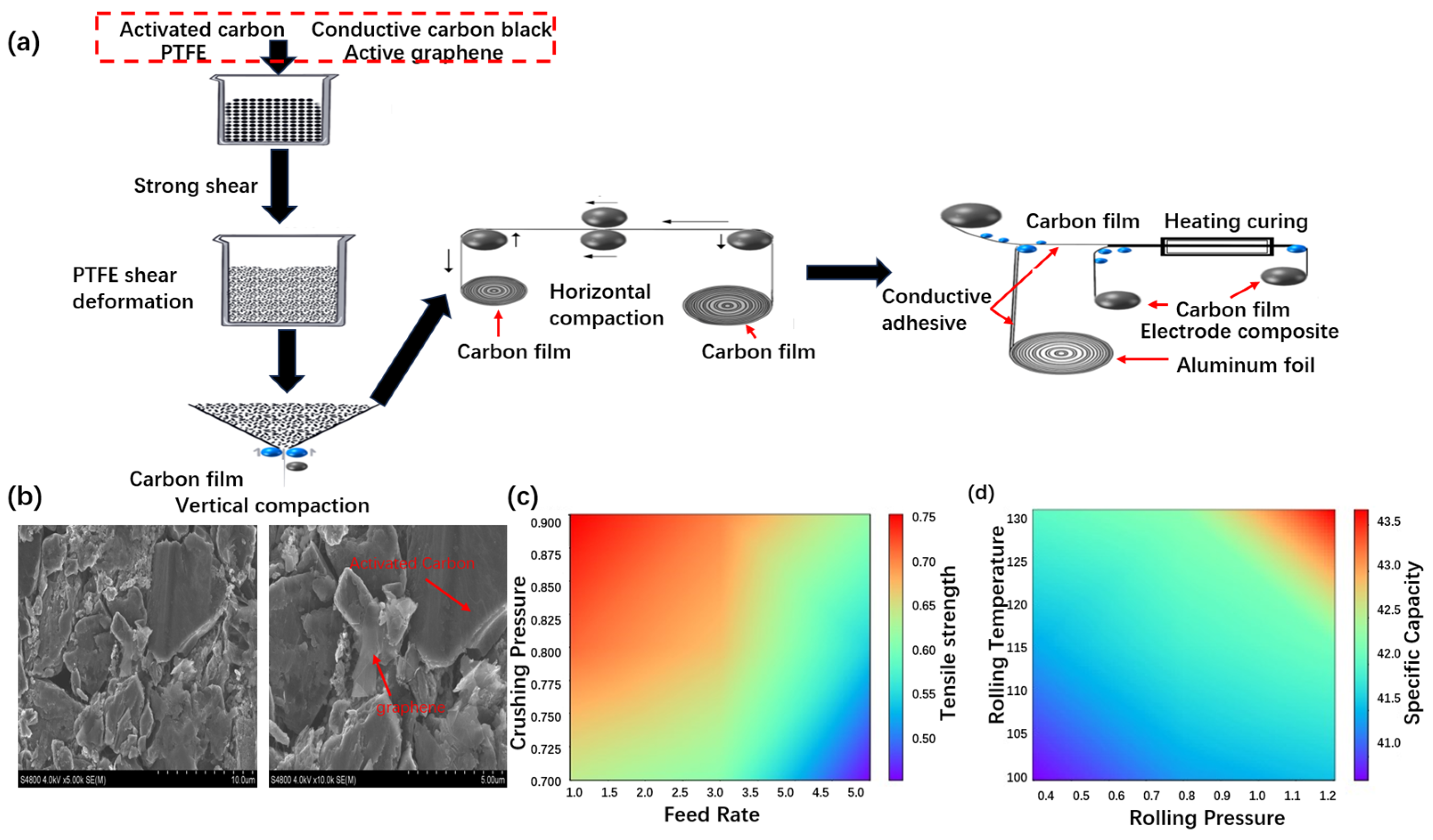
3.1. Preparation of Graphene/Activated Carbon Hybrid Electrode

Typically, graphene oxide has a high content of oxygen functional groups on the surface (5–10%), which is prone to both blocking the abundant pores of the activated carbon and inducing gas-producing side reactions at high potentials. Therefore, if graphene oxide and activated carbon hybrids are directly used to prepare electrodes, this will cause problems such as increased internal resistance and the decreased capacity of capacitors.
To fully harness the electrochemical energy storage advantages of graphene materials while mitigating the negative impacts of oxygen-containing functional groups, we have proposed a one-step carbonization activation method for synthesizing porous graphene/activated carbon hybrids, as illustrated in the process flow diagram depicted in Figure 1. The TEM image reveals that the activated products exhibit a wrinkled nanosheet structure with layered porosity, as highlighted by the red circle in Figure 1c. This observation indicates that KOH activation effectively etches and creates pores. The abundant voids formed during the activation process further enhance the specific surface area of the hybrid material, enabling greater energy storage capacity. Leveraging the porous graphene material with a specific surface area exceeding 2000 m2/g (as a comparison, the results in the literature [28] are only 1861 m2/g), pore size distribution ranging from 2 to 5 nm, and pore volume of 2.4 mL/g, we homogeneously mixed it with petroleum coke and potassium hydroxide using ultra-high-speed centrifugal dispersion technology. Subsequently, the carbonization and activation of petroleum coke, as well as the activation and reduction of graphene, were accomplished at high temperatures, resulting in the formation of high-specific-surface-area porous activated carbon with a three-dimensional conductive network structure, integrated with activated graphene hybrids.
The morphology of the porous graphene/activated carbon hybrid material is depicted in Figure 1b. As evident from the figure, the product post-one-step carbonization activation retains a wrinkled sheet-like structure akin to the original graphene, featuring a certain degree of agglomeration. The surface is enveloped in an amorphous carbon layer, exhibiting rough and wrinkled features. This graphene/activated carbon hybrid material is theoretically superior in electrochemical energy storage characteristics, yet it proves challenging to produce electrode films using traditional wet processes. This is because capacitors are highly sensitive to moisture during the preparation process. Yet, the traditional wet electrode preparation process necessitates the use of solvents like deionized water to regulate the slurry’s viscosity. Even high-temperature and high-vacuum drying processes struggle to eliminate the moisture introduced by the wet electrode. This moisture not only makes the electrode prone to delamination but also leads to increased leakage currents in capacitors, compromising the long-term stability of the product. Additionally, while traditional wet electrode preparation processes boast strong continuous production capabilities and relatively low engineering application difficulties, they result in low electrode densities (usually less than 0.6 g/cm3), which in turn limit the capacity and voltage endurance of the individual cells (to less than 2.7 V) [29]. Hence, traditional wet processes fail to produce electrode films of graphene/activated carbon hybrids with superior electrochemical performance.
To enhance the voltage resistance and electrode density, this study independently developed a dry preparation technique, as illustrated in Figure 2a.
Initially, we developed ultra-high-speed shear dispersion technology. This process breaks down the agglomeration of micrometer-sized carbon materials, achieving uniform solid-phase mixing. Additionally, ultra-high-speed intense shearing transforms the chain-like polymer structure of the dry powder adhesive polytetrafluoroethylene (PTFE), transforming it from a cluster to a network configuration, evenly distributing it across the surface of the carbon-based hybrid material. This ensures that the electrode does not lose powder, fall off, or rebound during subsequent production steps, thereby enhancing the supercapacitor’s long service life. Research on carbon film formation technology utilizes low-temperature vertical rolling to synergistically produce high-density carbon films with electrode hybrids and PTFE. Research on heat-curing rolling technology integrates electrode materials with current collectors by hot-rolling hybrid carbon films and graphene conductive adhesive-coated aluminum foils. Leveraging this dry preparation technique, the electrode density can be increased to 0.65–0.7 g/cm3 (as a comparison, the results in the literature [30] are only 0.59 g/cm3), significantly improving the mass of active material per unit volume and significantly enhancing both the overall capacity and specific energy of the monomers.
Furthermore, this process eliminates the liquid-phase steps entirely, avoiding the introduction of moisture that significantly impacts the voltage window, thereby facilitating an increase in the monomer’s window voltage.
The microstructure of the hybrid dry electrode sheet is shown in Figure 2b. From the figure, it can be seen that the carbon particles in the electrode sheet are tightly stacked, indicating that the density of the electrode sheet can be increased by the above process, thus increasing the content of active material in the monolithic capacitor. Meanwhile, the size of active graphene is close to the size of active carbon particles, which proves that the above ultra-high-speed shear dispersion technique makes the active graphene well dispersed in the hybrid electrode sheet. Additionally, Figure 2b reveals sheet-like porous graphene (as indicated by the arrow, with a smoother surface) and activated carbon (as indicated by the arrow, in a blocky particle structure), both of which are well dispersed. The high magnification scanning electron microscope (Figure 3b) photo further confirms that the flake active graphene is well dispersed and connected to the active carbon particles, and it also acts as a conductive bridging agent.
The key technology in the dry electrode manufacturing process is the fibrilization of the binder. This is mainly achieved by pulverizing the spherical PTFE binder fibers with a high-pressure air stream. The degree of fibrillation is mainly influenced by factors such as feed rate and comminution pressure. Samples with a length of 9 cm and a width of 1 cm were used for testing. It was experimentally verified that the slower the feed rate and the higher the grinding pressure, the higher the degree of binder fibrillation, the higher the dry electrode film strength, and the better the electrode sheet quality. Figure 2c shows the experimental data for the feed rate, comminution pressure, and tensile strength of the sample with a length of 9 cm and a width of 1 cm. At a feed rate of 1 kg/h and a squeezing pressure of 0.9 MPa, corresponding to the top left point on the data graph, the carbon film has the highest tensile strength along its length.
Dry electrode rolling is the key process from powder to dry electrode sheet. The rolling pressure and temperature directly affect the electrode density and ultimately determine the specific capacitance of the capacitor monolith. It is experimentally verified (the process parameters are shown in Figure 2d) that the higher the rolling pressure and the higher the rolling temperature, the higher the electrode density and the higher the specific capacitance of the monomer.

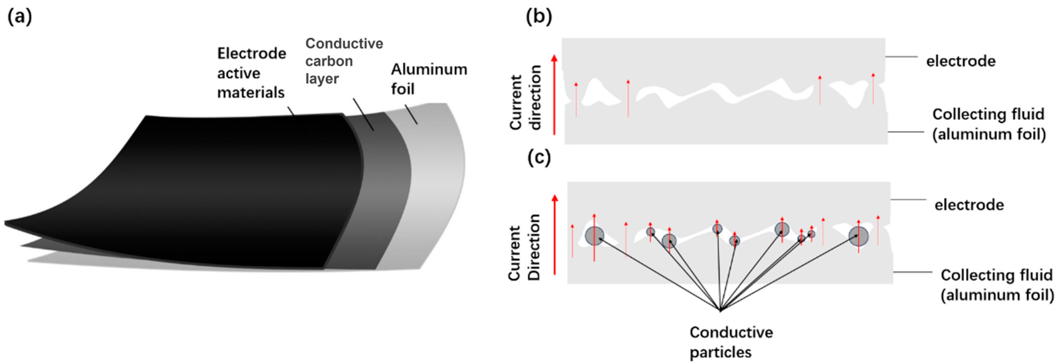
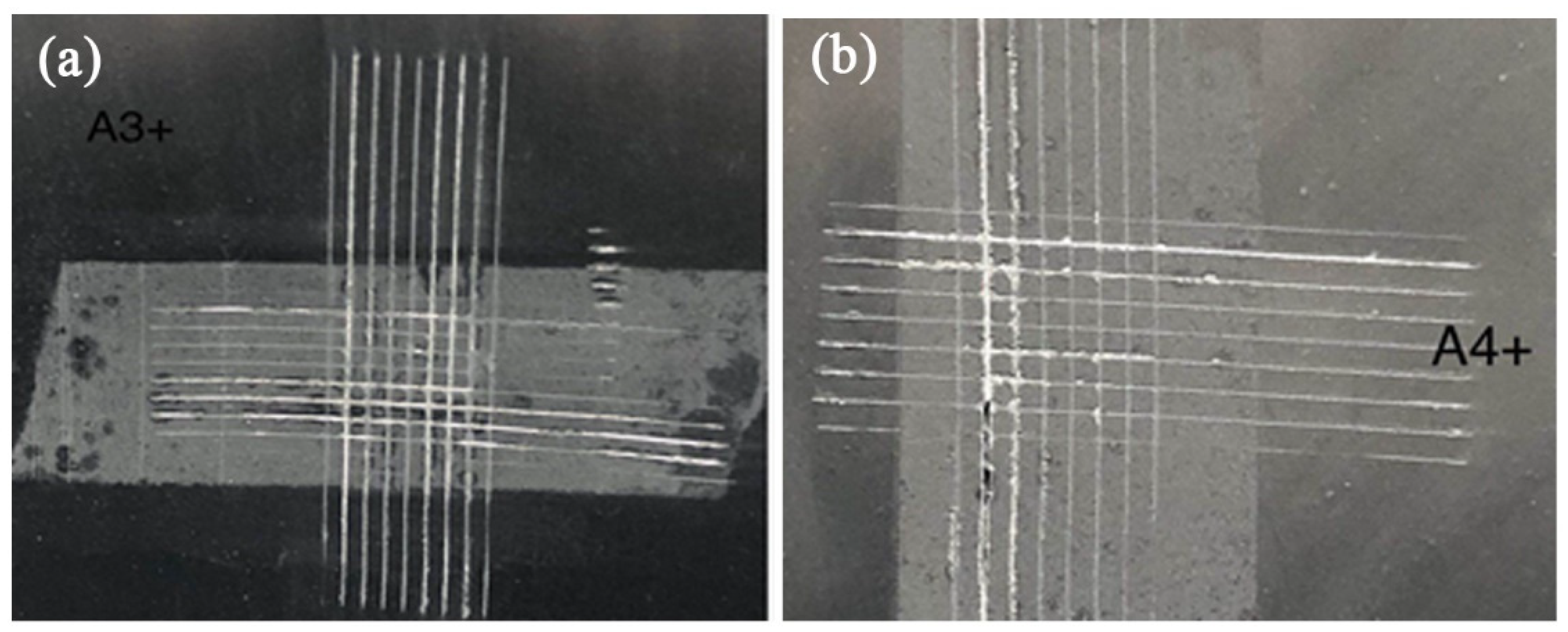
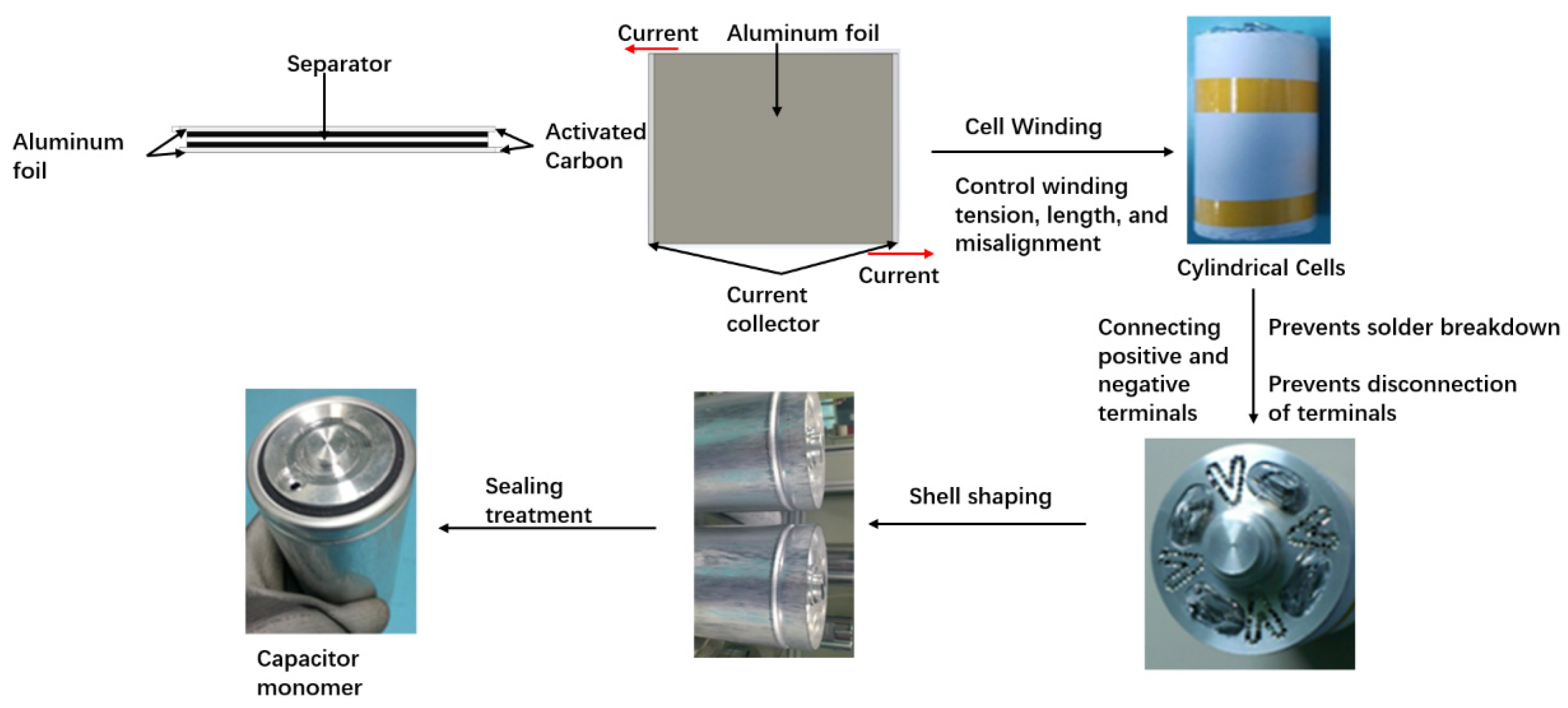
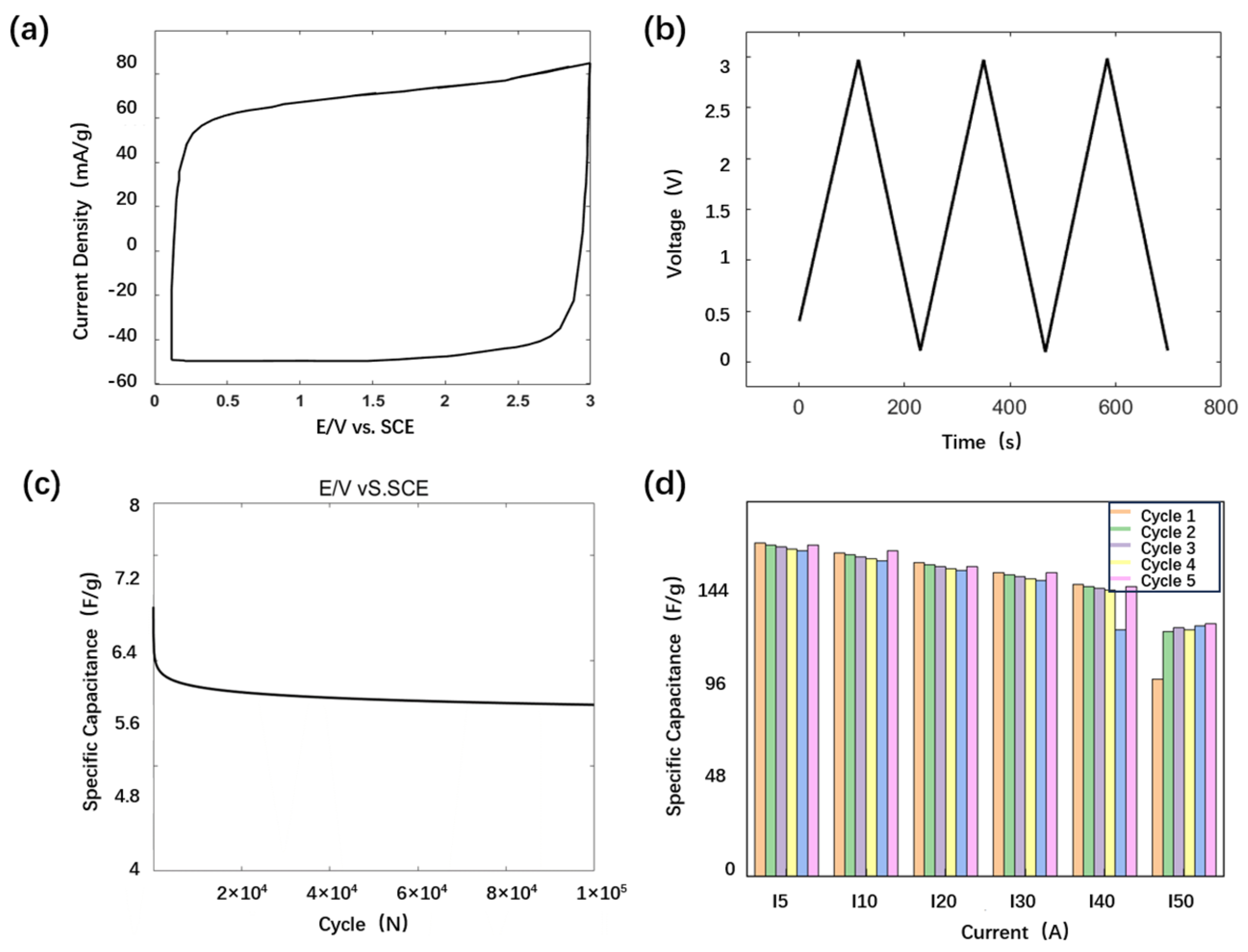
3.2. Fabrication of Collector-Optimized Supercapacitor

The current collector, which is the carrier material for the electrode material in the composition of capacitors, serves the function of current collection and support. It should possess the attributes of conductivity, corrosion resistance, and overload resistance. Commonly utilized current collectors include stable metal foils or meshes such as Al, Cu, Ni, or Ti, which are known to exhibit high conductivity [31,32,33,34,35,36]. In specific contexts, rare or precious metals may be employed as current collector materials. In power double-layer capacitors, aluminum foil is typically employed as a current collector due to its advantageous qualities, including high electrical conductivity, low cost, and corrosion resistance. However, due to its high reactivity, the surface of aluminum current collectors tends to form a poorly conductive aluminum oxide film, which increases the resistance between the current collector and the active material and reduces adhesion between them. Therefore, appropriate treatments of aluminum current collectors are necessary.
In the context of industrial applications, the surface treatment of aluminum foil for supercapacitors primarily involves etching. The resulting material, designated “corroded foil”, exhibits superior adhesion to electrode materials compared to unetched aluminum foil, yet it exhibits reduced conductivity and mechanical strength and is associated with a higher production cost, largely driven by the reliance on imports of the required raw materials.
The coating of carbon on aluminum foil involves the application of a layer of carbon film (with a thickness of less than 5 micrometers) to the surface of the foil, with the addition of conductive agents such as conductive graphite, carbon black, carbon nanotubes, and graphene. This coating has the effect of significantly reducing the interface resistance between the electrode sheet and the aluminum foil, while also enhancing the adhesion between the active material and the current collector. Furthermore, the coating can also serve to partially suppress the corrosion of the current collector. Consequently, the utilization of this novel type of current collector can facilitate the enhancement of the high-rate charge–discharge capability and cycle life of batteries. The schematic diagram of the structure is depicted in Figure 3a. In the absence of a coating, the contact between interfaces is insufficient, resulting in a reduction in the number of current pathways and a restriction of the flow of the current. The coating facilitates improved contact between the particles, thereby enhancing the current and performance, as illustrated in Figure 3b,c.
Figure 4 presents a comparative analysis of the adhesion properties of various collector electrode coatings. The procedure for testing adhesion can be described as follows: the electrode is placed onto a flat plate of sufficient hardness, the handle of the baguette cutter is held so that the multi-flute cutter is perpendicular to the plane of the test piece, and the cut is made with uniform pressure and at a cutting speed of 20–50 mm/s. The polarizer is then rotated through 90 degrees, the aforementioned operation is repeated at the cutting place to form a grid pattern, and the electrode piece is gently brushed with a soft brush along the two diagonals of the grid pattern, backwards and forwards five times each. Finally, the electrode piece is tested. Upon observation, it was noted that there were small pieces of flaking at the intersection of the cuts. Additionally, the actual damage in the grid area was found to be less severe. The adhesion of the two types of poles, carbon and aluminum foil coated and corroded aluminum foil, is essentially comparable. It has been demonstrated that the carbon aluminum foil coating can enhance the adhesion between the porous carbon material and the collector.
Figure 5 illustrates the alterations in the internal resistance and capacity of 100F capacitors assembled with distinct current collector electrodes during high-temperature ageing. From the graph, it can be observed that, during the 500 h high-temperature ageing process, the rate of the increase in the internal resistance of carbon-coated aluminum foil current collector capacitors is relatively gentle, while the rate of capacity retention is higher than that of corroded foil current collector capacitors. This suggests that coated aluminum foil can markedly reduce the interface resistance between the electrode and aluminum foil, thereby enhancing the stability of the electrode.
In the development of cylindrical devices, the manner in which the tabs are connected and lead out can serve to reduce the internal resistance of the device and increase the power density. In this paper, we have employed a full tab structure in the design of the electrode tab structure with the objective of enhancing the current-carrying capability. The full electrode tab structure is depicted in Figure 6. Initially, the activated carbon was coated on an aluminum foil, with the diaphragm placed between two layers of activated carbon. Thereafter, the activated carbon, aluminum foil, and diaphragm were wound into a compact structure. Following winding, the area of the aluminum foil is marginally larger than that of the toner, with both toner ends encompassing a portion of aluminum foil. The aluminum foil serves as electrode tabs, with the upper end connected to the negative collector as a whole and the lower end connected to the positive collector in the same manner. The negative collector is connected to the top cover, while the positive collector is connected to the bottom case. In this configuration, the cover and the case act as the two ends of the capacitor, with the capacitors able to output voltage to the outside and be insulated from each other. Furthermore, the lead-in terminals employ the direct lead-in method in lieu of the conventional indirect lead-in method. The structure is illustrated in Figure 6, which entails soldering the lead foil directly to the lead-out terminals. The protrusions of the lead-in terminals pass directly through the through-holes of the housing and extend outwardly from the housing. The direct lead-in structure design significantly reduces the internal resistance and enhances the power performance of the supercapacitor.
A trial production of capacitors based on the aforementioned materials and structures was conducted. In order to verify the withstand voltage characteristics of the capacitor, a cyclic voltammetry (CV) test was first conducted on the capacitor, with a voltage range of 0–3 V and a scanning speed of 5 mV/s. The cyclic voltammetry (CV) curve is presented in Figure 7a. The CV curve approximates a rectangular structure, reflecting favorable capacitance characteristics, particularly at a high voltage (3V). The absence of an evident oxidation curve in the CV indicates that, under high voltage, the electrode is relatively stable and no significant side reactions occur. This indicates that the capacitor has a stable structure at 3V. It should be noted that the current used in the test was I40 = 5 A, I10 = 1.25 A, and I5 = 0.625 A.
The capacitor’s charging and discharging test range is illustrated in Figure 7b, spanning a voltage range of 0–3 V. This range exhibits a regular triangular sawtooth shape and clear capacitance behavior. To ascertain the capacitor’s operational lifetime, we conducted cyclic tests, and the results are presented in Figure 7c. Following the completion of the cycling tests, the observed capacity decay was found to be relatively minor, thereby indicating that the capacitor in question has a longer lifespan. In order to ascertain the rate performance of the capacitor, charge–discharge tests were conducted on individual capacitors at different rates. The voltage range was 0–3 V, and the charge–discharge current was 5–50 I. Each rate of current was subjected to five cycles of charge–discharge. The test results are presented in Figure 7d. The initial capacity is 165 F (under 5 I testing conditions), and as the testing current increases (5 I to 30 I), the capacity does not decay significantly, demonstrating good rate performance. Upon increasing the charging and discharging current to 40 I, a slight decrease in capacity was observed. At a test current of 50 I, the capacity is approximately 125 F, with a capacity retention rate of 75.8%. Furthermore, following repeated cycles of charge and discharge testing under different magnification currents, the capacitor did not demonstrate any notable gas swelling, suggesting that it has excellent voltage resistance. Furthermore, electrochemical impedance spectroscopy (EIS) testing was conducted on supercapacitors, with the results presented in the Supplementary Materials. It should be noted that the internal resistance of the capacitor prepared in this work is about 0.06 mΩ (as a comparison, the results in the literature [28] are only 0.5 Ω). Table 1 shows some specific test data for capacitors, such as weight, internal resistance, power density and energy density.

4. Discussion

In this paper, porous graphene/activated carbon hybrids were prepared by a one-step carbonization activation process on the basis of porous graphene materials with a specific surface area of more than 2000 m2/g, a pore size distribution of 2–5 nm, and a void volume of 2.4 mL/g. An ultra-high-speed centrifugal dispersion technique was employed to achieve a homogeneous slurry comprising graphene oxide, petroleum coke, and potassium hydroxide. At elevated temperatures, petroleum coke undergoes carbonization and activation, while graphene undergoes activation and reduction to form a three-dimensional conductive network structure of high-specific-surface-area porous activated carbon/activated graphene hybrids. The product that resulted from the one-step carbonization and activation process exhibited a folded sheet structure that was similar to that of pristine graphene. However, it also contained some agglomerates and was coated with an amorphous carbon layer that exhibited a rough and folded surface. The development of ultra-high-speed shear dispersion technology was employed to ensure the long-term service life of the supercapacitors. The hybrid electrodes prepared using dry technology exhibited a notable enhancement in total capacitance and specific energy relative to the monomer. The development of an all-pole tab high-power soft-packed capacitor with good voltage resistance, large monomer power density, and excellent electrochemical performance was achieved through the dry preparation of electrode sheets as electrodes. The capacitor’s performance was evaluated through cyclic voltammetry, which demonstrated that the electrode exhibited stability at high voltages without significant side reactions. The results of the cyclic testing of the capacitors demonstrated a relatively small reduction in capacitance, indicating that they have a relatively long life. Conversely, the capacitor did not exhibit any discernible gas expansion following multiple charge/discharge tests with varying amplification currents, thereby indicating that the capacitor exhibits robust voltage resistance.

Supplementary Materials

The following supporting information can be downloaded at: https://www.mdpi.com/article/10.3390/batteries10060195/s1, Table S1. Test data of electrodes prepared by two methods, Table S2. Electrical conductivity of several metals, Figure S1: AC Impedance Spectrum of Supercapacitors.

Author Contributions

Conceptualization, X.W.; methodology, S.C.; validation, S.C.; formal analysis, W.W. and X.Z.; investigation, S.C.; data curation, S.C.; writing—original draft preparation, S.C. and W.W.; writing—review and editing, X.W.; visualization, X.Z.; supervision, X.W.; All authors have read and agreed to the published version of the manuscript.

Funding

This research received no external funding.

Data Availability Statement

Data is contained within the article or Supplementary Material.

Conflicts of Interest

The authors declare no conflict of interest.

References

  1. Arunkumar, C.R.; Manthati, U.B.; Punna, S. Supercapacitor-based transient power supply for DC microgrid applications. Electr. Eng. 2022, 104, 463–472. [Google Scholar] [CrossRef]
  2. Fernando, J.; Kularatna, N.; Silva, S.; Thotabaddadurage, S.S. Supercapacitor assisted surge absorber technique: High performance transient surge protectors for consumer electronics. IEEE Power Electron. Mag. 2022, 9, 48–60. [Google Scholar] [CrossRef]
  3. Luo, L.; Lan, Y.; Zhang, Q.; Deng, J.; Luo, L.; Zeng, Q.; Gao, H.; Zhao, W. A review on biomass-derived activated carbon as electrode materials for energy storage supercapacitors. J. Energy Storage 2022, 55, 105839. [Google Scholar] [CrossRef]
  4. Jiang, Y.; Li, J.; Jiang, Z.; Shi, M.; Sheng, R.; Liu, Z.; Zhang, S.; Cao, Y.; Wei, T.; Fan, Z. Large-surface-area activated carbon with high density by electrostatic densification for supercapacitor electrodes. Carbon 2021, 175, 281–288. [Google Scholar] [CrossRef]
  5. Nithya, V.D. A review on holey graphene electrode for supercapacitor. J. Energy Storage 2021, 44, 103380. [Google Scholar] [CrossRef]
  6. Yang, Z.; Tian, J.; Ye, Z.; Jin, Y.; Cui, C.; Xie, Q.; Wang, J.; Zhang, G.; Dong, Z.; Miao, Y.; et al. High energy and high power density supercapacitor with 3D Al foam-based thick graphene electrode: Fabrication and simulation. Energy Storage Mater. 2020, 33, 18–25. [Google Scholar] [CrossRef]
  7. Yan, Z.; Gao, Z.; Zhang, Z.; Dai, C.; Wei, W.; Shen, P.K. Graphene nanosphere as advanced electrode material to promote high performance symmetrical supercapacitor. Small 2021, 17, 2007915. [Google Scholar] [CrossRef] [PubMed]
  8. Jiang, Q.; Liu, D.; Liu, B.; Zhou, T.; Zhou, J. Blotting paper-derived activated porous carbon/reduced graphene oxide composite electrodes for supercapacitor applications. Molecules 2019, 24, 4625. [Google Scholar] [CrossRef]
  9. Thalji, M.R.; Ali, G.A.; Liu, P.; Zhong, Y.L.; Chong, K.F. W18O49 nanowires-graphene nanocomposite for asymmetric supercapacitors employing AlCl3 aqueous electrolyte. Chem. Eng. J. 2021, 409, 128216. [Google Scholar] [CrossRef]
  10. Wang, J.; Li, Q.; Peng, C.; Shu, N.; Niu, L.; Zhu, Y. To increase electrochemical performance of electrode material by attaching activated carbon particles on reduced graphene oxide sheets for supercapacitor. J. Power Sources 2020, 450, 227611. [Google Scholar] [CrossRef]
  11. Iakunkov, A.; Skrypnychuk, V.; Nordenström, A.; Shilayeva, E.A.; Korobov, M.; Prodana, M.; Enachescu, M.; Larsson, S.H.; Talyzin, A.V. Activated graphene as a material for supercapacitor electrodes: Effects of surface area, pore size distribution and hydrophilicity. Phys. Chem. Chem. Phys. 2019, 21, 17901–17912. [Google Scholar] [CrossRef] [PubMed]
  12. Ramadoss, A.; Kim, S.J. Improved activity of a graphene–TiO2 hybrid electrode in an electrochemical supercapacitor. Carbon 2013, 63, 434–445. [Google Scholar] [CrossRef]
  13. Costentin, C.; Savéant, J.M. Energy storage: Pseudocapacitance in prospect. Chem. Sci. 2019, 10, 5656–5666. [Google Scholar] [CrossRef] [PubMed]
  14. George, J.; Balachandran, M. Extrinsic pseudocapacitance: Tapering the borderline between pseudocapacitive and battery type electrode materials for energy storage applications. J. Energy Storage 2023, 74, 109292. [Google Scholar] [CrossRef]
  15. Aderyani, S.; Flouda, P.; Shah, S.A.; Green, M.J.; Lutkenhaus, J.L.; Ardebili, H. Simulation of cyclic voltammetry in structural supercapacitors with pseudocapacitance behavior. Electrochim. Acta 2021, 390, 138822. [Google Scholar] [CrossRef]
  16. Park, H.W.; Roh, K.C. Recent advances in and perspectives on pseudocapacitive materials for supercapacitors—A review. J. Power Sources 2023, 557, 232558. [Google Scholar] [CrossRef]
  17. Hu, Y.R.; Dong, X.L.; Zhuang, H.K.; Yan, D.; Hou, L.; Li, W.C. Introducing Electrochemically Active Oxygen Species to Boost the Pseudocapacitance of Carbon-based Supercapacitor. ChemElectroChem 2021, 8, 3073–3079. [Google Scholar] [CrossRef]
  18. Bokhari, S.W.; Siddique, A.H.; Sherrell, P.C.; Yue, X.; Karumbaiah, K.M.; Wei, S.; Ellis, A.V.; Gao, W. Advances in graphene-based supercapacitor electrodes. Energy Rep. 2020, 6, 2768–2784. [Google Scholar] [CrossRef]
  19. Down, M.P.; Rowley-Neale, S.J.; Smith, G.C.; Banks, C.E. Fabrication of graphene oxide supercapacitor devices. ACS Appl. Energy Mater. 2018, 1, 707–714. [Google Scholar] [CrossRef]
  20. Zhang, S.; Pan, N. Supercapacitors performance evaluation. Adv. Energy Mater. 2015, 5, 1401401. [Google Scholar] [CrossRef]
  21. Ke, Q.; Wang, J. Graphene-based materials for supercapacitor electrodes—A review. J. Mater. 2016, 2, 37–54. [Google Scholar] [CrossRef]
  22. Li, Z.J.; Yang, B.C.; Zhang, S.R.; Zhao, C.M. Graphene oxide with improved electrical conductivity for supercapacitor electrodes. Appl. Surf. Sci. 2012, 258, 3726–3731. [Google Scholar] [CrossRef]
  23. Zhang, H.; Yang, D.; Lau, A.; Ma, T.; Lin, H.; Jia, B. Hybridized graphene for supercapacitors: Beyond the limitation of pure graphene. Small 2021, 17, 2007311. [Google Scholar] [CrossRef] [PubMed]
  24. Zequine, C.; Bhoyate, S.; de Souza, F.; Arukula, R.; Kahol, P.K.; Gupta, R.K. Recent advancements and key challenges of graphene for flexible supercapacitors. In Adapting 2D Nanomaterials for Advanced Applications; American Chemical Society: Washington, DC, USA, 2020; pp. 49–77. [Google Scholar]
  25. Pameté, E.; Köps, L.; Kreth, F.A.; Pohlmann, S.; Varzi, A.; Brousse, T.; Balducci, A.; Presser, V. The many deaths of supercapacitors: Degradation, aging, and performance fading. Adv. Energy Mater. 2023, 13, 2301008. [Google Scholar] [CrossRef]
  26. Kurzweil, P.; Schottenbauer, J.; Schell, C. Past, present and future of electrochemical capacitors: Pseudocapacitance, aging mechanisms and service life estimation. J. Energy Storage 2021, 35, 102311. [Google Scholar] [CrossRef]
  27. Pegel, H.; Wycisk, D.; Scheible, A.; Tendera, L.; Latz, A.; Sauer, D.U. Fast-charging performance and optimal thermal management of large-format full-tab cylindrical lithium-ion cells under varying environmental conditions. J. Power Sources 2023, 556, 232408. [Google Scholar] [CrossRef]
  28. Zhang, J.; Zhao, Y.; Zang, X.; Wang, B.; Ma, F. Application of three-dimensional porous graphene in high-magnification supercapacitors. Energy Eng. 2020, 58–64. [Google Scholar] [CrossRef]
  29. Balducci, A.; Dugas, R.; Taberna, P.L.; Simon, P.; Plée, D.; Mastragostino, M.; Passerini, S. High temperature carbon-carbon supercapacitor using ionic liquid as electrolyte. J. Power Sources 2007, 165, 922–927. [Google Scholar] [CrossRef]
  30. Liu, F.; Xue, L. Effect of moulding process on the performance of activated carbon electrodes for supercapacitors. Electron. Compon. Mater. 2017, 36, 25–28. [Google Scholar]
  31. Dai, X. Research and Application of Modified Aluminum Foil Current Collector and Interface Optimization by Electric Spark Method in Supercapacitors. Master’s Thesis, Jilin University, Changchun, China, 2020. [Google Scholar]
  32. Zhang, D.; Wu, Y.; Li, T.; Huang, Y.; Zhang, A.; Miao, M. High performance carbon nanotube yarn supercapacitors with a surface-oxidized copper current collector. ACS Appl. Mater. Interfaces 2015, 7, 25835–25842. [Google Scholar] [CrossRef]
  33. Chae, C.; Han, J.H.; Lee, S.S.; Choi, Y.; Kim, T.H.; Jeong, S. A printable metallic current collector for all-printed high-voltage micro-supercapacitors: Instantaneous surface passivation by flash-light-sintering reaction. Adv. Funct. Mater. 2020, 30, 2000715. [Google Scholar] [CrossRef]
  34. An, G.H.; Cha, S.N.; Ahn, H.J. Surface functionalization of the terraced surface-based current collector for a supercapacitor with an improved energy storage performance. Appl. Surf. Sci. 2019, 478, 435–440. [Google Scholar] [CrossRef]
  35. Yu, J.; Yu, C.; Guo, W.; Wang, Z.; Ding, Y.; Xie, Y.; Liu, K.; Wang, H.; Tan, X.; Huang, H.; et al. Insight into the effects of current collectors and in situ Ni leaching in high-voltage aqueous supercapacitors. Adv. Funct. Mater. 2022, 32, 2204609. [Google Scholar] [CrossRef]
  36. Ruan, D. Dynamic Double-Layer Capacitors—Principles, Manufacturing, and Applications; Science Press: Beijing, China, 2018. [Google Scholar]
Figure 1. (a) Schematic diagram of one-step carbonization activation method for preparing porous graphene/activated carbon hybrid materials; (b) SEM image of porous graphene/activated carbon hybrid material; (c) TEM image of porous graphene/activated carbon hybrid material.
Batteries 10 00195 g001
Figure 2. Preparation process and properties of the hybrid electrode film. (a) Dry preparation process; (b) electron microscope photographs; (c) mechanical properties; (d) specific capacity.
Batteries 10 00195 g002
Figure 3. Carbon-coated aluminum foil collector. (a) Three-layer structure; (b) mechanisms of the conventional conductivity of the interfacial contact; (c) enhanced mechanism of interfacial contact conductivity.
Batteries 10 00195 g003
Figure 4. The comparative diagram of film adhesion on different current collector electrodes: (a) coating carbon aluminum foil; (b) corroded aluminum foil.
Batteries 10 00195 g004
Figure 5. Contribution of carbon-coated aluminum foil to durability. (a) Conductivity; (b) capacity retention.
Batteries 10 00195 g005
Figure 6. Fabrication process for supercapacitors with full tab structure [36].
Batteries 10 00195 g006
Figure 7. Performance testing of supercapacitors. (a) Cyclic voltammetry; (b) charging and discharging with constant current; (c) cycling performance; (d) rate performance.
Batteries 10 00195 g007
Table 1. Test data of cylindrical capacitors.
NumberWeight (g)Capacity (F)Specific
Energy (Wh/Kg)
Internal
Resistance (mΩ)
Power
Density (kW/kg)
Capacitance
Retention (%)
1#543.529606.810.06662.7281.5%
2#534.529026.790.05773.8580.3%
Disclaimer/Publisher’s Note: The statements, opinions and data contained in all publications are solely those of the individual author(s) and contributor(s) and not of MDPI and/or the editor(s). MDPI and/or the editor(s) disclaim responsibility for any injury to people or property resulting from any ideas, methods, instructions or products referred to in the content.

