Article

Edible Gelatin and Cosmetic Activated Carbon Powder as Biodegradable and Replaceable Materials in the Production of Supercapacitors

by
Rodica-Cristina Negroiu
1,*,
Cristina-Ioana Marghescu
1,
Irina-Bristena Bacis
1,
Madalina-Irina Burcea
1,
Andrei Drumea
1,
Laurentiu Dinca
2 and
Ion Razvan Radulescu
2
1
Centre of Technological Electronics and Interconnection Techniques, National University of Science and Technology POLITEHNICA Bucharest, 060042 Bucharest, Romania
2
National Research and Development Institute for Textiles and Leather (INCDTP), 030508 Bucharest, Romania
*
Author to whom correspondence should be addressed.
Batteries 2024, 10(7), 237; https://doi.org/10.3390/batteries10070237
Submission received: 15 May 2024 / Revised: 20 June 2024 / Accepted: 23 June 2024 / Published: 1 July 2024
(This article belongs to the Collection Feature Papers in Batteries)

Abstract

:
Environmental pollution is currently one of the most worrying factors that endangers human health. Therefore, attempts are being made to reduce it by various means. One of the most important sources of pollution in terms of the current RoHS and REACH directives is the pollution caused by the use of chemical products for the production of sources for the storage and generation of electricity. The aim of this article is therefore to develop supercapacitors made of biodegradable materials and to investigate their electrical performance. Among the materials used to make these electrodes, activated carbon was identified as the main material and different combinations of gelatin, calligraphy ink and glycerol were used as the binders. The electrolyte consists of a hydrogel based on gelatin, NaCl 20 wt% solution and glycerol. In the context of this research, the electrolyte, which has the consistency of a gel, fulfills the dual function of the separator in the structure of the manufactured cells. Due to its structure, the electrolyte has good mechanical properties and can easily block the contact between the two electrodes. Most of the materials used for the production of supercapacitor cells are interchangeable materials, which are mainly used in other application fields such as the food or cosmetics industries, but were also successfully used for the investigations carried out in this research. Thus, remarkable results were recorded regarding a specific capacitance between 101.46 F/g and 233.26 F/g and an energy density between 3.52 Wh/kg and 8.09 Wh/kg, with a slightly lower power density between 66.66 W/kg and 85.76 W/kg for the manufactured supercapacitors.

1. Introduction

As more and more electrical devices came onto the market, more power sources have gradually been developed for them, and the problem of environmental pollution has begun to limit the use of conventional materials in their manufacture. For this reason, increasing emphasis is being placed in the literature on the identification of environmentally friendly materials that make an important contribution to the development of various energy storage and generation sources. One of these sources is the supercapacitor, a component with several capabilities, such as a longer lifetime (it can withstand more than 100,000 charge and discharge cycles), a shorter charging time, the generation of high current values when needed and a wider operating temperature range compared with conventional batteries [1].
The supercapacitor has a structure consisting of two electrodes, a separator and an electrolyte solution. In his paper [2], Chuanyin Xiong and his co-workers provide important information about the structure of the supercapacitor and new materials based on airgels with various remarkable capabilities that can be used in the realization of supercapacitors. All component materials influence the function and capabilities of the component. They therefore determine the performance of the component itself.
Over time, however, researchers have increasingly identified solutions to improve the electrochemical performance of supercapacitors by using new materials. These materials are usually very expensive and thus the price of a commercial supercapacitor is quite high (on average EUR 30–40) [3]. A particular aspect is the degree of pollution of its components, which can be more or less environmentally friendly depending on the materials used. Therefore, much of the research in this area focuses on the use of materials with a low degree of pollution and a low price. When choosing such materials, one can opt for materials that have similar capabilities to those found on the websites of well-known manufacturers of chemical materials but which are mainly used in other application fields (food, cosmetics, pharmaceuticals, schools, etc.). For example, Peng and his colleagues [4] used commercially available ballpoint pen ink to produce a flexible electrode for a supercapacitor through a dip-coating process. They achieved impressive electrochemical performance in the form of a specific capacitance of 317.5 mF/cm2, a power density of 846 μW/cm2 and an energy density of 23.5 μWh/cm2. In another work [5], textile ink was used to obtain flexible cotton-based electrodes with a specific capacitance of 677.12 mF/cm2. In the preparation of the electrode material, it is necessary to use a binder in order to bind the particles of the active material and achieve good mechanical stability of the whole mixture but without significantly affecting the electrical conductivity [6]. Also, in this work, several variants of biodegradable materials were investigated instead of the well-known polyvinylidene fluoride or polyvinylidene difluoride (PVDF), which have low mechanical capabilities and thermal stability. It is soluble in a solvent with high toxicity and this aspect led to the identification of other alternatives in the choice of binder according to the current guidelines ([7,8,9]). Thus, cellulose, chitosan and lignin are mentioned in [10] as natural fibers whose capabilities are compatible or even superior to those of PVDF. In their work [11], Landi and his colleagues present a detailed comparison from an electrochemical point of view between different biopolymers such as chitosan, guar gum or gelatin and report the following specific capacitance values: for the electrode with guar gum as a binder, they obtained a specific capacitance of 11.9 F/g at 500 mV/s, the device with chitosan as a binder had a specific capacitance value of 39.1 F/g at 500 mV/s and the gelatin binder had a specific capacitance value of 11.6 F/g at 500 mV/s. They used NaCl 1 M as an electrolyte, with the aim of obtaining structures made of environmentally friendly materials and they used activated carbon as the active material. Other research papers [12,13] report gelatin as a biological binder, which is used in combination with glycerol, due to its performance in terms of homogeneous structure, good conductivity and mechanical stability.
Another interesting study [14] presents the development of a supercapacitor containing a gel electrolyte based on chia seed mucilage, exhibiting good electrochemical properties, such as a more rectangular curve in cyclic voltammetry (CV), a longer discharge time in galvanostatic charge discharge (GCD) and a low charge transfer resistance in electrochemical impedance spectroscopy (EIS), with a maximum specific capacitance of 7.77 F g−1 and a power density of 287.7 W kg−1.
One of the aims of this research is therefore to use materials with main utility in other application fields and that are much more cost-effective compared with the classic materials used traditionally for the production of supercapacitors. For example, finely chopped edible gelatin was used as the main material for the binder and the electrolyte: 10 g of edible gelatin costs about EUR 0.3. The active material in the structure of the electrodes was cosmetic activated carbon (CAC): 10 g of CAC costs about EUR 0.7. Glycerol was used in the recipe of a supercapacitor as part of the binder as well as in the structure of the electrolyte: 100 mL of glycerol costs about EUR 1.95. Calligraphy ink was used for the electrodes’ recipe in another supercapacitor: 60 mL of calligraphy ink costs about EUR 1. For more information on the materials, see Section 2 of the Materials and Methods. The fact that the usefulness of some materials has been reinterpreted, leading to the obtaining of supercapacitor cells from biodegradable materials with low costs and promising capabilities brings a certain degree of novelty to the current research in this field. Obtaining a hydrogel based on gelatin, sodium chloride (20 wt%) and glycerol, which plays a dual role in the structure of supercapacitors, namely as an electrolyte and as a separator, is a strength of this work, since one of the important components, which is present in the classical supercapacitor, was excluded in the present case. In order to obtain a recipe for the hydrogel presented in the work, many trials and combinations of different amounts of materials were necessary until a structure was achieved that can be easily detached from the Petri dish and later mechanically handled in the assembly of the supercapacitors. Furthermore, the capabilities of the obtained hydrogel can be successfully applied in flexible supercapacitor structures. Thus, they can be integrated into storage and power supply systems for portable devices, which represents a large application field in the present and future development. In recent years, research in this field has expanded and more and more researchers have started to use replaceable and biodegradable materials.

2. Materials and Methods

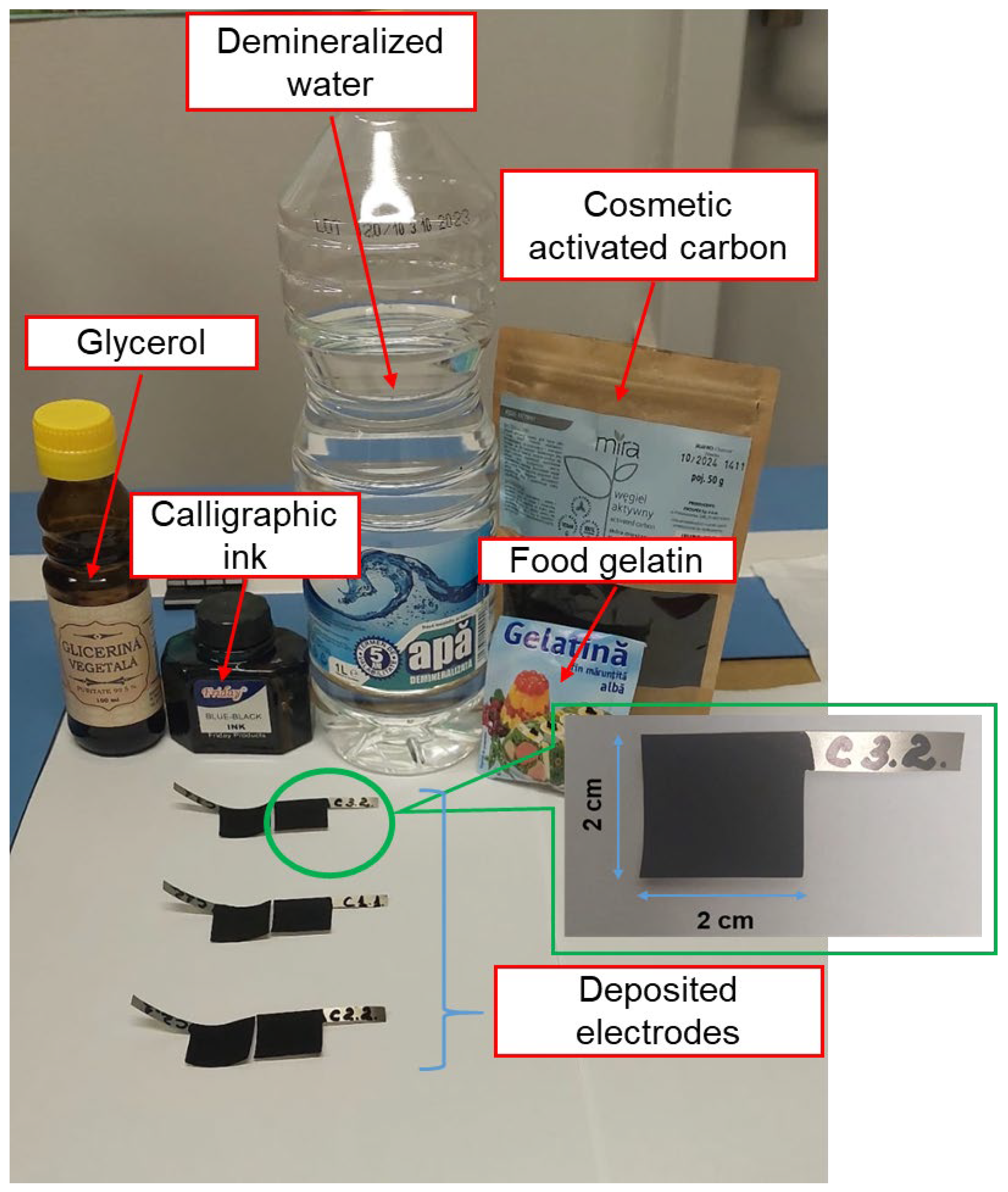
2.1. Preparation of the Material for the Electrode

Three recipes were used to prepare the electrode material, containing activated carbon as the active material and gelatin as the main binder. Three pairs of electrodes were produced with these three recipes. The substrate is a nickel foil that was purchased from Nanografi [15]. The substrate also plays the role of a collector as it was properly profiled with a size of 2 cm × 2 cm. This foil was chosen due to its compatibility with the used electrolyte, (sodium chloride—NaCl), in order that the substrate should not corrode over time, as is the case with aluminum foil, for example. The formulation of the material for the first pair of electrodes (C1.1 and C1.2) was prepared as follows: A material of cosmetic activated carbon (CAC) 95 wt% as active material [16] and gelatin + glycerol 5 wt% as binder was prepared. The gelatin and glycerol solution was prepared by dissolving 1.25 g of finely ground gelatin in 10 mL of demineralized water and 2.5 mL of glycerol. The gelatin was left to soak in the solution of water and glycerol and later dissolved in a steam bath. To incorporate the entire amount of activated carbon and to obtain an easy-to-handle composition, 2 mL of demineralized water was added over the entire mixture of CAC and binder. The mixture was continuously mixed with a vertical stirrer for 30 min until a composition with a homogeneous structure was obtained and subsequently deposited on the Ni foil substrate. For the second pair of electrodes (C2.1 and C2.2), a material with the same CAC in a proportion of 95 wt% with another and a binder from gelatin + calligraphy ink in a proportion of 5 wt% was prepared. The binder solution was prepared in the same way as in the previous case, with the exception that 2.5 mL glycerol was replaced by 2.5 mL calligraphy ink. The rest of the procedure for obtaining and depositing the material on the substrate was identical to the previous case. The role of the ink is to create a better adhesion of the material and an increase in the electrical conductivity for the whole structure [17], while the glycerol provides better flexibility and reduces viscosity [18]. For the last pair of electrodes (C3.1 and C3.2), only gelatin as a binder in the same ratio (5 wt%) and CAC (95 wt%) as an activated material was used, while omitting glycerol and ink. The preparation procedure was similar to the previous cases except that 1.25 g of gelatin and 12.5 mL of demineralized water to prepare the binder was used.
All samples were weighed before and after deposition of the material on the substrate to determine the amount of material deposited (see Table 1).
Figure 1 shows the materials used to make the three pairs of electrodes and the electrodes after drying.
Figure 1 shows that all electrodes have a relatively homogeneous and dense surface without macroscopic holes or cracks. This indicates that the material was well dispersed on the surface of the substrate and that the 48 h drying at room temperature facilitated the achievement of uniform nanostructures.

2.2. Joint Preparation of the Electrolyte and the Separator

The electrolyte used in this study had the form of a hydrogel and was prepared on the basis of gelatin, sodium chloride (NaCl) and glycerol. To prepare it, 13 mL of NaCl solution (20 wt% solution) and 7 mL of glycerol were added to 5 g of finely ground gelatin. The mixture was allowed to stand for 10 min to moisten the gelatin and then placed in a steam bath until the finely ground gelatin was completely dissolved (about 2 min) and a solution was obtained. The solution was mixed with a glass spatula to dissolve the gelatin while it was in the steam bath. The gelatin could be destroyed if the solution was boiled. Therefore, it should not remain in the steam bath for long time but until the finely ground gelatin is completely dissolved [19].
In the next step, we poured the solution into Petri dishes and allowed the solution to gel. The gelling process took about 3 h. The edges of the resulting film were peeled off to make it easier to remove the gel and we proceeded to assemble the supercapacitor cells. Removing the hydrogel from the Petri dish was carried out with great care, as the resulting structure was stickier due to the glycerol in the composition. The resulting gel electrolyte can be seen in Figure 2. It has a thickness of 2 mm.
This type of electrolyte has the consistency of water. As such, it can be concluded that the maximum working voltage of the manufactured cells must not exceed the electrolytic decomposition voltage of the water in the electrolyte composition of 1.23 V [20]. Otherwise, the cells would be destroyed by the phenomenon of electrolytic decomposition.
Due to the good mechanical capabilities of the electrolyte and the fact that it blocks the contact between the two electrodes of each fabricated supercapacitor cell, the gel electrolyte also plays the role of a biodegradable separator within the fabricated structures. The fact that the manufactured hydrogel fulfills a dual function is a major advantage.

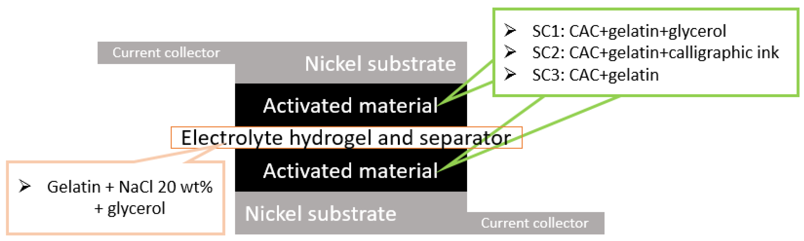
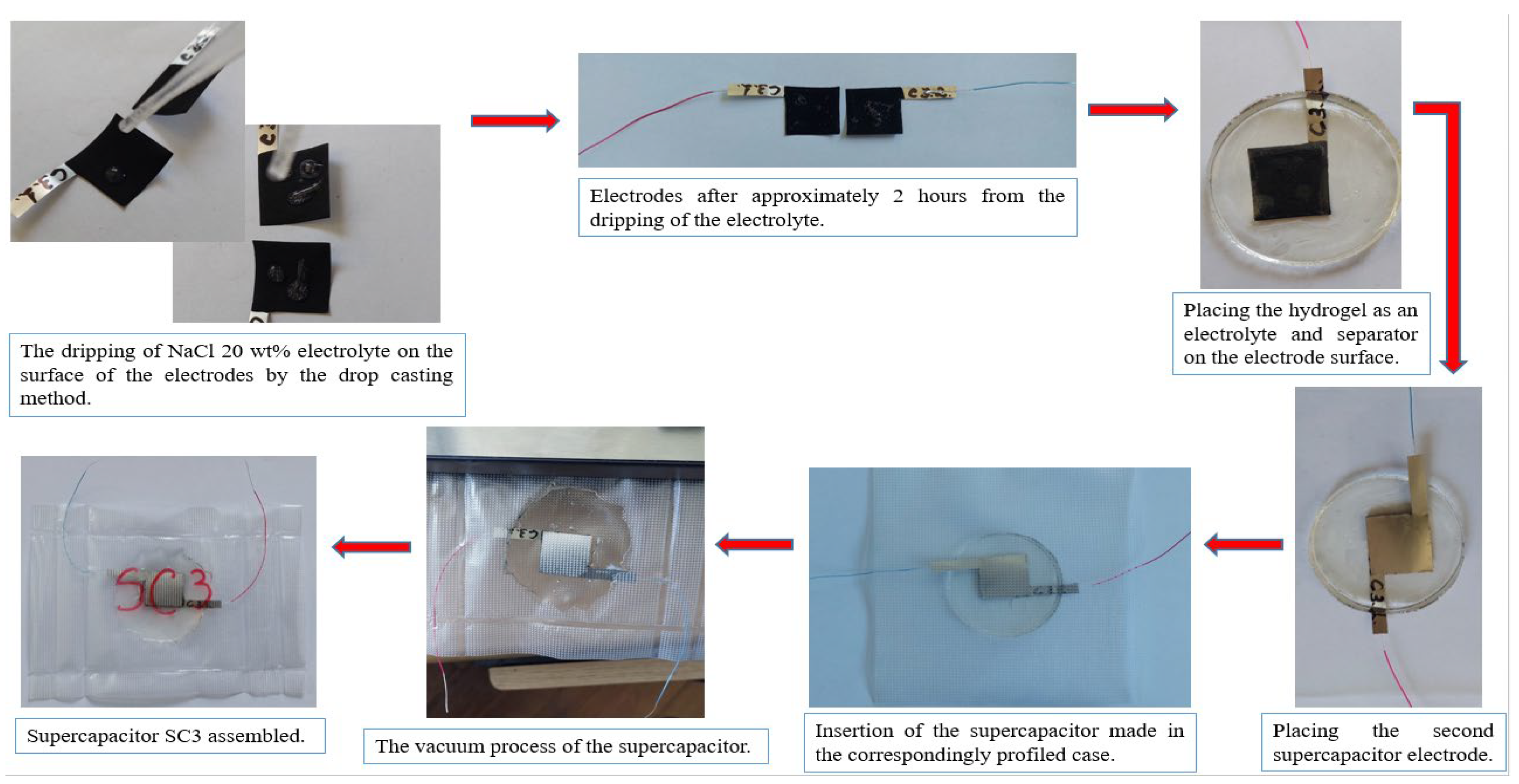
3. Assembly of Supercapacitor Cells
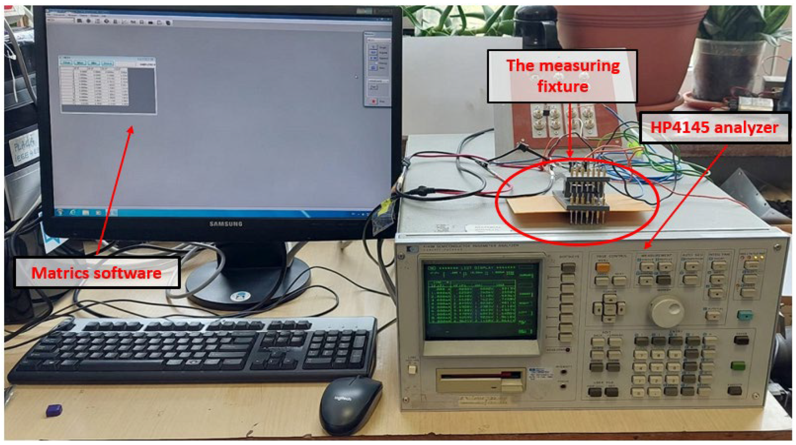
The assembly of the supercapacitor cells is a meticulous process and must be carried out with great care. As can be seen in Figure 3, the double role separator has a larger diameter compared with the length of the electrodes to provide a safety measure in terms of possible contact between the two electrodes. To ensure that there was enough electrolyte in the fabricated structures, 200 μL NaCl 20 wt% was applied to the surface of electrodes C1.1, C1.2, C2.1 and C2.2 and 300 μl NaCl 20 wt% to the surface of electrodes C3.1 and C3.2 using the drop-casting method. For about 2 h, the dripped electrolyte penetrated into the structure of the electrode material. The structures made in the form of a sandwich were placed in plastic casings, which were profiled according to the size of the cells, sealed on three sides and vacuum-sealed on the fourth side using a vacuum device. This prevents possible oxidation and corrosion, which can occur on contact with the external environment, as well as possible leakage of the electrolyte [20]. In order not to hinder the sealing of the casings, a thin wire with a diameter of 0.3 mm was soldered to each electrode before dripping the electrolyte, which was later used to connect the measuring devices for the tests. The assembly process is shown in Figure 4 for the supercapacitor SC3.
After assembling the 3 supercapacitor cells, designated SC1, SC2 and SC3, they were left to soak for 24 h [21]. This was followed by the galvanostatic test part and the determination of their electrical performance.

4. Test Methods

4.1. Test Method for Electrodes

Before assembling the supercapacitor cells, the structure of the electrodes was carefully analyzed by determining the electrical resistivity and conductivity. Electrode testing was performed with an HP4145B semiconductor parameter analyzer equipment from Yokogawa Hewlett-Packard Company, Tokyo, Japan. Based on the measurements taken after testing the 8 manufactured electrodes, the two parameters were calculated using the 4-point measurement. To best fix the samples during the tests and make the measurements as accurate as possible, a fixture with pins positioned at equal distances from each other was used [22].
For the measurements with the HP4145 analyzer, the following procedure was applied: the Matrics software was configured by applying a current of 100 mA and by setting the cut-off voltage to 20 V, the maximum allowable value of the device. A series of measurements in 11 points up to 100 mA from 10 mA was carried out for each electrode. The same current values at a greater distance between the pins (about 12 mm) were applied and the voltage was measured at two points about 4 mm apart, applying different current values within the points, in order to determine the electrical resistivity and conductivity.
The measuring stand used for this test performed on the electrodes is presented in Figure 5.
After testing the electrodes and obtaining favorable results in terms of electrical conductivity values (presented in Section 5), the cells were assembled and galvanostatically tested.

4.2. Galvanostatic Testing of Supercapacitors

The galvanostatic tests consisted of carrying out charge–discharge cycles at different voltage values with charge–discharge current values of 4 mA and 8 mA, respectively.
An appropriately configured measuring stand was used make these measurements. It consisted of an IT6720 power supply for charging the supercapacitors, a Keithley 2700 multimeter for monitoring the voltage at the cell terminals, a BK Precision 8500B active load for discharging the supercapacitors with a constant current down to a voltage of 0 V and the ExceLinx software, version ELNX-851C04 for controlling the multimeter via the GPIB-USB interface and for storing the experimental data. The experimental data were later processed and are presented in Section 5, Section 5.3. Figure 6 shows the measuring stand used for the galvanostatic tests of the supercapacitors.

5. Results and Discussion

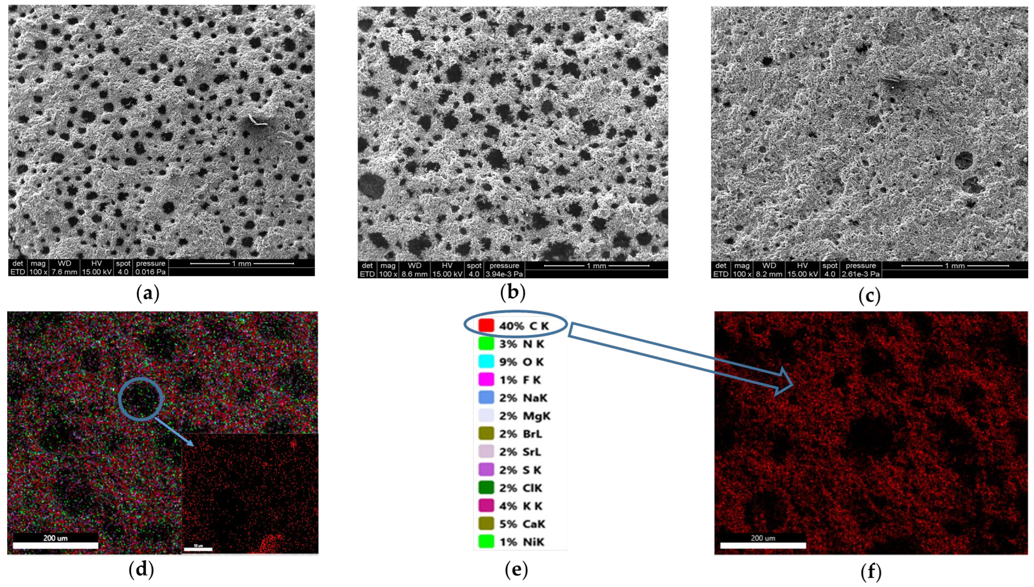
5.1. Morphological Analyses

A detailed examination of the morphology of the samples was carried out using a morphology Scanning Electron Microscope (SEM) with Energy Dispersive X-Ray Analysis (EDX) using a high-resolution microscope Quanta (FEI Company, Eindhoven, The Netherlands). The EDX analysis made it possible to determine the materials contained in the composition of the samples for the manufacture of the electrodes and their percentage share in the overall structure [23]. The SEM images of the samples showed that they have no cracks, but in all the analyzed samples, certain elevations were found that were initially considered cavities. In an initial analysis, as shown in Figure 7a–c, these cavities appeared to be voids. However, a higher resolution scan revealed that they were covered by a film and that a structure similar to the entire deposited material could be seen under this film when using a deeper focus. An in-depth analysis of these areas in the structure of the electrodes was therefore carried out to investigate whether they represent macroscopic voids that could, in turn, reduce the overall active surface area of the electrodes. Figure 8 shows in an up to 6000× resolution scan that there is indeed a structure behind the film that is similar to the material structure of the rest of the monitored sample. Since gelatin was used as the main binder in all the electrode samples, the film formed was most likely gelatin. In the EDX images, most of the carbon used as active material can be seen in red, but chemical elements present in the structure of gelatin such as carbon, hydrogen, nitrogen and oxygen also appear [24]. Glycerol and calligraphic ink contain in their chemical composition carbon, hydrogen and oxygen, calcium, potassium, strontium, boron, etc. Of all three investigated samples prepared with different biomaterials as binders, SEM analysis showed that the sample using only gelatin as a binder had the most homogeneous structure with few gelled areas. The presence of these gelled areas may be caused on the one hand by the presence of ink or glycerol in the binder structure and the chemical reaction of these two elements with the gelatin, or, on the other hand, by the mechanical process of preparing the material for the electrode. Perhaps a small time delay in the preparation of the mixture caused the binder to gel before the actual mixing with the active material. However, it is assumed that the chemical action of gelatin with calligraphy ink and glycerol is the main cause of the appearance of gelled areas in the structure of the electrodes. It is important to mention that after the galvanostatic tests of the fabricated supercapacitors, the positive or negative influence of the presence of these areas on the electrical performance of the fabricated cells was determined.
The mapping of chemical elements carried out on the first sample, CAC (active material) + gelatin + glycerol (binder), which corresponds to the composition of the pair of electrodes C1.1 and C1.2, shows that carbon is the most abundant element (40%), while the other elements belonging to the gelatin and glycerol binder are present in much lower proportions. The nickel substrate is present at a low percentage of 1. The percentage of activated carbon in the analyzed gelled area is 35% (see Figure 7d–f).

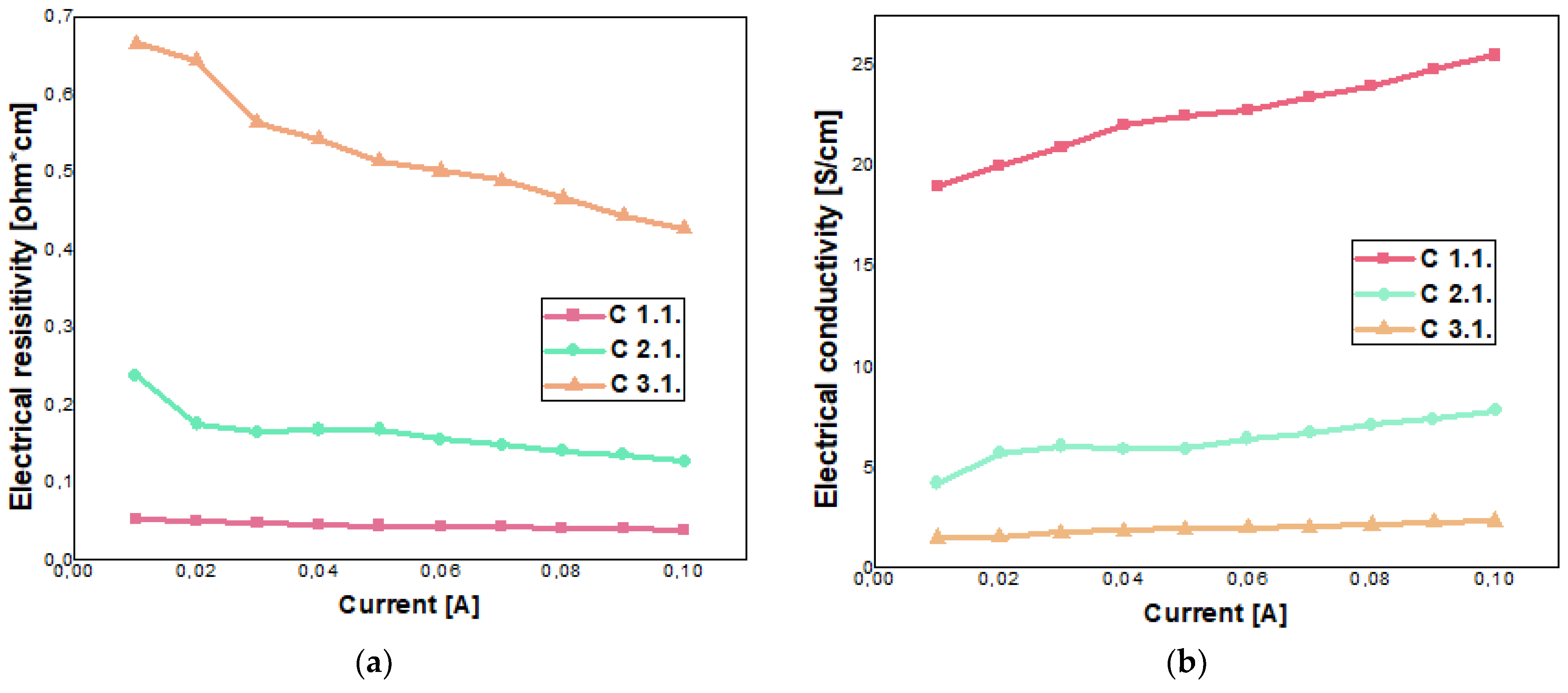
5.2. Electrodes Investigation

The experimental data were processed and Equations (1) and (2) were used to determine the electrical resistivity and electrical conductivity for one electrode from each pair [25].
ρ [ × m ] = 4.532   ×   weight   ×   V I ,
σ   [ S / m ] = 1 ρ ,
where ρ is the electrical resistivity, σ is the electrical conductivity, ∆V represents the difference between the voltage measured between the internal points of the mount, named VS1P and VS2P in Matrics software, and I is the applied current, named IF1P in Matrics software. The results obtained are presented in Table 2.
These results confirm a good electrical conductivity, within the upper and lower limits of the categories of conductive and semiconductive materials, with an electrical resistivity between 10−5 ÷ 102 Ω × cm. After analyzing the experimental data, it can be concluded that the presence of glycerol and ink in a ratio of 2.5 mL in the structure of the binder causes an increase in electrical conductivity. Remarkable results are observed when glycerol is used in the structure of the binder.
In order to obtain more meaningful results, we performed measurements at 11 points, starting from 0 mA to 100 mA with a step of 10 mA. The graphical representations of electrical resistivity and electrical conductivity for the investigated electrodes after analyzing the experimental data are shown in Figure 9.
Both the data processed and the graphs produced show that the electrical resistivity of the three samples decreases and the electrical conductivity increases as the value of the current applied to the external terminals of the assembly increases. The same behavior can be observed in the tested samples as in the measurement with a current of 100 mA. The lowest values of electrical resistivity were measured for electrode C1.1 and the highest values for electrode C3.1.

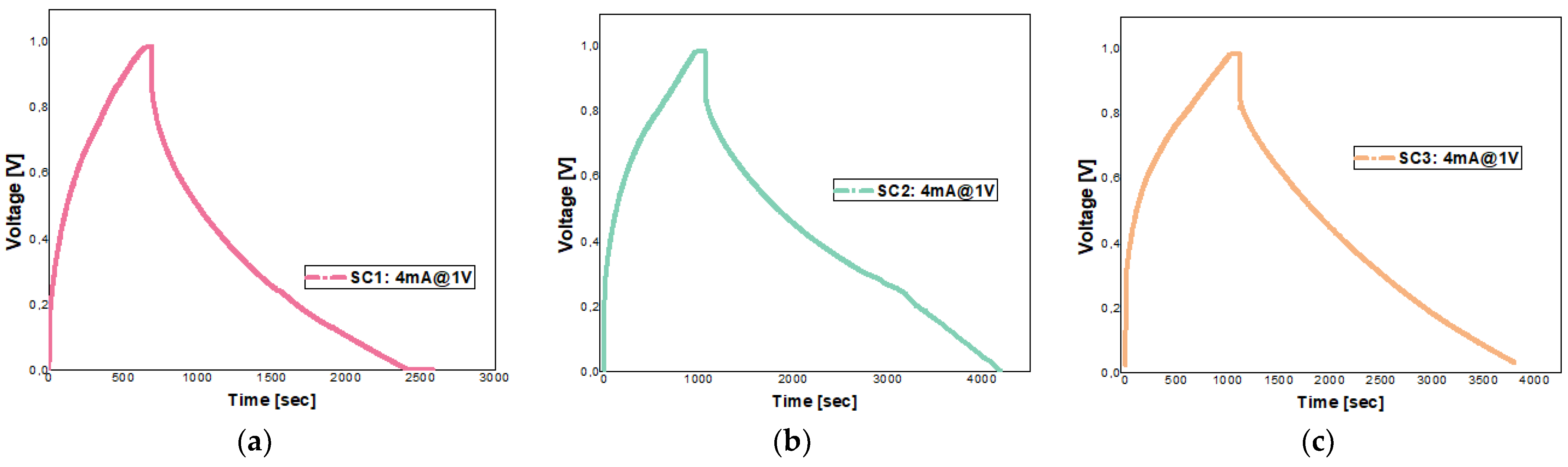
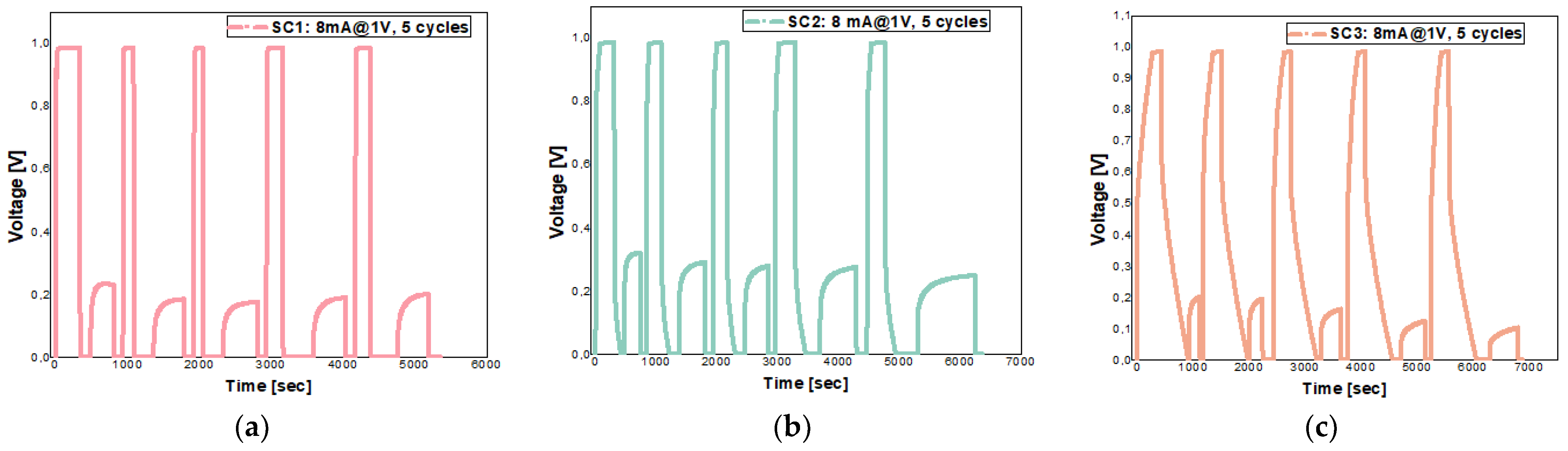
5.3. Galvanostatic Investigation for Supercapacitors Cells

The initial tests were carried out with a maximum voltage of 0.5 V and a charge–discharge current of 4 mA. Later, the maximum voltage was doubled and the current was kept at the same value as in the first test. The tests were started with a lower voltage value to avoid destroying the supercapacitor cells and to determine their progressive operation. The experimental data were processed and two important electrical parameters for commercial applications were determined, namely the electrical capacitance (CSC) and the equivalent series resistance (ESR). They were determined using relations (3) and (4):
E S R = Δ U 2 × I
C S C = I × ( t 2 t 1 ) 0.8 0.4 × U m a x
where I is the charge–discharge current and ΔU represents the sudden voltage drop immediately after the start of the discharge process, when the supercapacitor transitions from voltage stabilization to the discharge with a constant current. t1 is the time when the voltage reaches 80% of Umax, and t2 represents the time when the voltage reaches 40% of Umax,, respectively [26].
The obtained values are presented in Table 3 and charge–discharge caracteristics up to the maximum voltage of 1 V with a charge–discharge current of 4 mA for the three supercapacitors are presented in Figure 10.
Based on the values obtained after testing the three cells at voltages of 0.5 V and 1 V, it can be seen that SC2 has the best performance compared with the other two supercapacitors in terms of the two calculated parameters, electrical capacitance and ESR.
Once the electrical capacitance for each supercapacitor cell were determined, the specific capacitance [F/g] was calculated according to a certain principle, based on the previously obtained data. The capacitance of a supercapacitor is given by the series connection of the capacitances of the two electrodes in its structure. It is assumed in our research that the two electrodes are identical.
C S C [ F ] = C e l e c t r o d e 2 = >   C e l e c t r o d e = 2 × C S C ,
The mass of the entire supercapacitor expressed in grams for identical electrodes is as follows:
m S C g = 2 × m e l e c t r o d e ,
The specific capacitance is obtained by replacing Equations (5) and (6) in Equation (7):
C s p F g = 2 × C S C m S C 2 = 4 × C S C m S C ,
Using the above equation, the specific capacitance was calculated on the basis of the electrical capacitance values determined at the maximum voltage of 1 V. To determine the mass of the deposited material, the mass of the non-deposited nickel (mass current collector) was subtracted from the mass of the dry-deposited electrode, based on the data in Table 1.
After determining the specific capacitance for the three supercapacitors SC1, SC2, and SC3, the energy density and power density for each cell was determined using Equations (8) and (9).
D e n s E W s e c g = 1 2 × C S C m × V 2 = > D e n s E W h k g = 1 2 × 3.6 × C S C m × V 2 ,
D e n s P W g = V 2 4 × m × E S R = > D e n s P W k g = V 2 4 × 10 3 × m × E S R
Thus, based on the above formulas, the energy density and power density at a maximum voltage of 1 V and a charge–discharge current of 4 mA were determined for each supercapacitor using the data from the galvanostatic tests.
The results of the calculations are shown in Table 4.
The results for specific capacitance are very good and can be successfully compared with the results of other studies published in this area. Railanmaa and co-workers reported a specific capacitance of 20–25 F/g for supercapacitors printed with a non-toxic, durable, gelatin-based aqueous gel electrolyte in their paper [27]. In their studies, other researchers have obtained a specific capacitance of 36 F/g when using gelatin as a lubricant in the structure of a carbon-based electrode, which decreased to 11.6 F/g with the increase in the sampling rate [12]. Wang and coworkers determined a specific capacitance of 145.14 F/g for a supercapacitor fabricated with lignin and gelatin electrolyte [28].
As can be seen from the calculations, the supercapacitor SC2 has the best capabilities in terms of power and energy density when compared with SC1 and SC3. Since the determined ESR value is higher, it has a negative effect on the power density value. So, in the case of this parameter, we have obtained quite small values compared with the results of other researchers in this field.
By comparing the results obtained for the two parameters of energy density and power density for the fabricated cells with other results available in the literature, it can be concluded that the fabricated supercapacitors are quite good in terms of energy density, but in terms of power density, the results were mostly unfavorable, due to the increased value of ESR. For example, when Landi and his coworkers used gelatin as a binder in the structure of the electrodes, they obtained an energy density of 3 Wh/kg and a power density of 1000 W/kg [11]. In [28], the researchers achieved an energy density of 4.86 Wh/kg for a supercapacitor made with an electrolyte based on lignin and gelatin.
During the subsequent charging tests, a pseudo-capacitive effect occurred for each supercapacitor, i.e., after discharging to a voltage of 0 V, rapid self-charging was observed at the terminals of each cell. The fact that they charge after they have been fully discharged is due to the fact that the process is reversible and redox reactions (reduction and oxidation) take place, which in turn cause the pseudo-capacitive effect. In these types of capacitors, which exhibit pseudo-capacitive behavior, a Faraday charge transfer takes place in the porous material of which the electrode is made, based on reduction and oxidation reactions [29]. These reactions lead to a behavior similar to that of rechargeable batteries, which are based on electrochemical reactions. The redox reactions that take place at the electrode level must be reversible or semi-reversible to ensure an efficient charge/discharge process. For this type of component, besides reversibility, another important aspect is the possible choice of reagents [30]. We can say that a reversible process is good if the electrooxidation of the reduction state of a pseudo-material can take place at the same electrode potential as the electroreduction of the oxidation state. To determine whether the pseudocapacitive process is reversible, we performed five consecutive charge–discharge cycles up to a maximum voltage of 1 V with a charge–discharge current of 8 mA. The graphs of voltage as a function of time for SC1, SC2 and SC3 are shown in Figure 11.
From the data obtained, it can be seen that the pseudocapacitive effect (self-charging) is maintained at the terminals of the supercapacitors, especially in the case of SC1. In the case of cells SC2 and SC3, the self-charge effect seems to decrease as the supercapacitors are recharged, starting from 0.32 V at SC2 and 0.2 at SC3, respectively, with voltage values recorded at the first cycle, and reaching 0.25 V at SC2 and 0.1 V at SC3, respectively, with values recorded after the fifth charge–discharge cycle.

5.4. Cyclic Voltammetry

For the realization of a cyclic voltammetry, given the existing infrastructure in our research center, an attempt was made to come up with an alternative to the classic measurements, using the Keithley 4200-SCS (Semiconductor Characterization System) equipment operated by Keithley Interactive Test Environment software. Thus, the voltage range was set between −1 V and 1 V, taking into account the electrolytic decomposition voltage of the electrolyte, a step of 0.05 V, but the device determines the current at the respective points but does not expect the voltage on the component to reach that point, and it does not wait for the supercapacitor to charge, given the software capabilities. The software determines, at the respective voltage values to which it was set, the value of the current through the component. In this way, the current-voltage characteristic for SC2 is the one shown in Figure 12.
Considering the obtained current-voltage characteristic, we consider that, if the software used would have allowed keeping a time until the supercapacitor had charged up to the set voltage, a characteristic similar to what is found in the specialized literature [31] might have been realized in the case of these components. In the section of the graph between −0.05 V and 0.05 V, the voltagram showed two rounded corners of the rectangle, with these being caused by the relatively high value of the series resistance of supercapacitor SC2. This has a value of 14.57 Ω at initial testing and 18.50 Ω when retesting the cells after 27 days. According to the studied literature [31,32], this series resistance is given by processes such as the transfer of ions in the electrode structure, the diffusion of ions in the structure of the hydrogel electrolyte made, the electrical connection between the electrodes and the test equipment or possibly errors that may occur in the assembly process. The phenomenon of the appearance of this characteristic caused by series resistance consists of the fact that the current passing through the component cannot respond quickly to changes in voltage. Thus, this deviation from the ideal characteristic appeared and a characteristic with two rounded corners was obtained in the voltage sweep range −0.05 V and 0.05 V. Given the fact that in the voltage sweep range between −0.05 V and 0.05 V, we can observe that CV characteristic, we conclude that in that voltage range, the supercapacitor managed to charge a little and store the electric charge within the time available on the duration of this test.

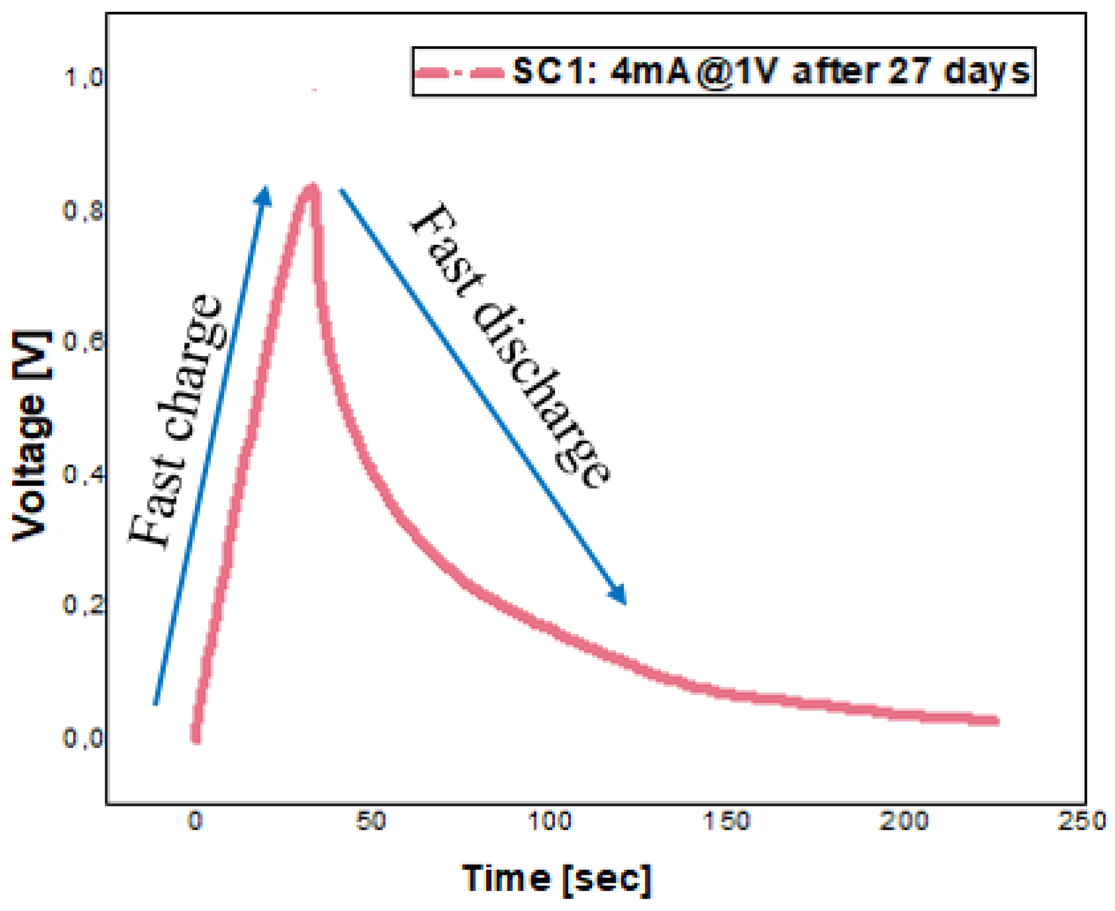
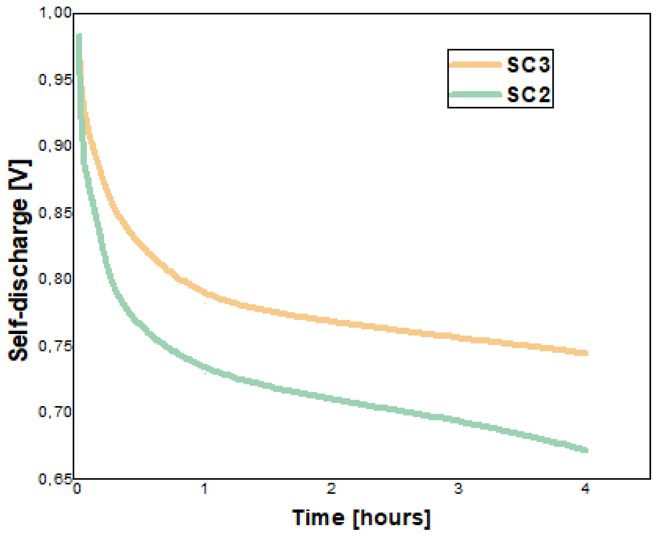
5.5. Stability of Supercapacitors over Time—Galvanostatic Testing after 27 Days

To determine how stable our supercapacitor cells are in terms of monitored electrical parameters over time, they were tested after 27 days under conditions similar to those presented in the section on galvanostatic testing for supercapacitor cells. The results of the monitored electrical parameters are shown in Table 5.
One of the first important aspects that caught our attention was the case of cell SC1, which suddenly reached the value of about 1 V when charging after 27 days, without a progressive charging process as in the initial tests, and which also discharged just as quickly (see Figure 13). This may represent a pertinent response to the results obtained in the case of SC1 in the initial tests, because even if the electrodes in the structure of SC1 showed the best results from the point of view of electrical conductivity, the results at the time of inclusion in the overall structure were less favorable compared with the other cells. We suppose that this was an error that occurred during assembly because the vacuum was not achieved and, over time, air entered the structure, which had undesirable effects that massively affected the supercapacitor. A decrease in capacitance and an increase in ESR over time was observed for the other two cells. The supercapacitor SC2 was the best preserved in terms of the electrical parameters determined. It retained about 60% of its electrical capacity and showed a 28% increase in ESR after 27 days.
To illustrate the effect of self-discharge on the two functional supercapacitors SC2 and SC3, the voltage at their terminals in open circuit was monitored for 4 h at different time intervals. The graphic representations are shown in Figure 14.
What can be observed in this test for both monitored functional supercapacitor cells is the fact that most of the self-discharge occurs in the first 5 min after the end of the charging process, a decrease of 0.116 V in the case of SC2 and a decrease of 0.073 V in the case of SC3. After an hour, the two supercapacitors end up self-discharging much less compared with how much they self-discharged in the first 5 min. Thus, we measured a self-discharge of 0.139 V at the terminals of SC2 after one hour in open circuit, and in the case of SC3, a self-discharge of 0.126 V. Then, the two cells were monitored hour by hour up to 4 h and we recorded a relatively constant self-discharge at each interval of approximately 0.02 V in the case of SC2 and approximately 0.015 V in the case of SC3. Thus, it can be concluded that the supercapacitors stabilized from the point of view of self-discharge. An uncontrollable part of the voltage at the terminals of the supercapacitors was also lost through the internal resistance of the used voltmeter.

6. Conclusions and Final Discussion

The results of the experimental data processing proved to be promising. The calculated electrical parameters showed more than satisfactory values compared with other values found in the literature in the same field. The fact that we used mostly biodegradable and replaceable materials in the development of the three supercapacitors, which are mainly used in other application fields, is a great advantage. One of the main advantages is the low price of the materials used, which means that the final product is much more cost-effective compared with other commercial supercapacitors with similar capabilities.
By discussing the electrical parameters of the manufactured supercapacitors in detail, at the testing of the electrodes, the best performance was found in the case of electrode C1.1, which is part of the final structure of SC1 (electrical resistivity of 39.16 × 10⁻³ Ω × cm and electrical conductivity of 25.53 S/cm); when the cell was assembled together with the roller and the separator electrolyte, its electrical capabilities in terms of the evaluated electrical parameters were relatively minimal (specific capacitance 101.46 F/g, ESR of 15.67 Ω, energy density of 3.52 Wh/kg and a power density of 83.96 W/kg) compared with the other two cells, and the main cause may be an error encountered in the process of sealing and vacuuming the cell as presented in the stability of supercapacitors over time—galvanostatic testing after 27 days subsection. As shown in Section 5, the best performances were recorded in the case of supercapacitor SC2, with a specific capacitance of 233.26 F/g, an ESR of 14.57 Ω, an energy density of 8.09 Wh/kg and a power density of 85.76 W/kg.
The electrical parameter for which we have obtained poor performance compared with the results recorded in the specialized literature was the ESR. This had a relatively great value and also had a significant impact on power density. Therefore, this aspect is a future challenge for our team and we will try to consistently improve this parameter through several experiments.
The fact that a hydrogel was obtained that plays a dual role, fulfilling both the qualifications of an electrolyte and a separator, is a positive outcome for our research.
The pseudo-capacitive effect present in the fabricated supercapacitors can be a great advantage in applications where these components can be embedded with a dual function, both from the perspective of energy storage and energy generation. This is mentioned because the supercapacitor can charge itself when no charging system is present. From previous research, it is known that the pseudo-capacitive effect comes from the hydrogel electrolyte. In the future, we will focus our attention on this process and try to control it by reducing, maintaining or increasing it as needed.

Supplementary Materials

The following supporting information can be downloaded at: https://www.mdpi.com/article/10.3390/batteries10070237/s1, Figure S1. The method used for testing the electrodes; Table S1. Electrical resistivity and electrical conductivity values for each investigated electrode from each pair of electrodes determined in 11 points from 0 mA to 100 mA; Figure S2. Energy density vs. power density in the case of the manufactured supercapacitors; Table S2. Presentation of the pseudocapacitive effect (self-charge values) in the case of SC1, SC2 and SC3 supercapacitors; Table S3. Self-discharge for SC2 and SC3 monitored at different time intervals of 4 h.

Author Contributions

Conceptualization, R.-C.N. and C.-I.M.; methodology, R.-C.N.; software, A.D.; validation, I.-B.B., M.-I.B. and R.-C.N.; formal analysis, L.D.; investigation, I.R.R.; resources, C.-I.M.; data curation, R.-C.N., L.D. and I.R.R.; writing—original draft preparation, R.-C.N., I.-B.B. and M.-I.B.; writing—review and editing, C.-I.M., I.R.R. and A.D.; funding acquisition, R.-C.N. All authors have read and agreed to the published version of the manuscript.

Funding

This research was funded by National University of Science and Technology POLITEHNICA Bucharest, Romania, under grant GNAC ARUT 2023, ID 220235170.

Data Availability Statement

The data presented in this study are available within this article and the Supplementary Material and they are available on request from the corresponding author.

Acknowledgments

This work was supported by a grant from the National Program for Research of the National Association of Technical Universities—GNAC ARUT 2023.

Conflicts of Interest

The authors declare no conflicts of interest.

References

  1. Yu, A.; Chabot, V.; Zhang, J. Electrochemical Supercapacitors for Energy Storage and Delivery Fundamentals and Applications; CRC Press; Taylor & Francis Group: New York, NY, USA, 2013; pp. 51–52. [Google Scholar]
  2. Kim, I.; San, S.T.; Mendhe, A.C.; Dhas, S.D.; Jeon, S.-B.; Kim, D. Rheological and Electrochemical Properties of Biodegradable Chia Mucilage Gel Electrolyte Applied to Supercapacitor. Batteries 2023, 9, 512. [Google Scholar] [CrossRef]
  3. TME. Available online: https://www.tme.eu/ro/katalog/elemente-pasive_112309/?queryPhrase=supercondensator&productListOrderBy=1000014 (accessed on 2 May 2024).
  4. Lv, P.; Song, L.; Li, Y.; Pang, H.; Liu, W. Hybrid ternary rice paper/polypyrrole ink/pen ink nanocomposites as components of flexible supercapacitors. Int. J. Hydrogen Energy 2021, 46, 13219–13229. [Google Scholar] [CrossRef]
  5. Keawploy, N.; Venkatkarthick, R.; Wangyao, P.; Qin, J. Screen printed textile electrodes using graphene and carbon nanotubes with silver for flexible supercapacitor applications. J. Met. Mater. Miner 2020, 30, 39–44. [Google Scholar] [CrossRef]
  6. Cholewinski, A.; Si, P.; Uceda, M.; Pope, M.; Zhao, B. Polymer Binders: Characterization and Development toward Aqueous Electrode Fabrication for Sustainability. Polymers 2021, 13, 631. [Google Scholar] [CrossRef] [PubMed]
  7. European Union. Available online: https://ec.europa.eu/environment/topics/waste-and-recycling/rohs-directive_ro (accessed on 10 April 2024).
  8. European Union. Available online: https://environment.ec.europa.eu/topics/chemicals/reach-regulation_en (accessed on 10 April 2024).
  9. European Union. Available online: https://environment.ec.europa.eu/topics/waste-and-recycling/waste-electrical-and-electronic-equipment-weee_en (accessed on 11 April 2024).
  10. Salleh, N.A.; Kheawhom, S.; Hamid, N.A.A.; Rahiman, W.; Mohamad, A.A. Electrode polymer binders for supercapacitor applications: A review. J. Mater. Res. Technol. 2023, 23, 3470–3491. [Google Scholar] [CrossRef]
  11. Landi, G.; La Notte, L.; Palma, A.L.; Sorrentino, A.; Maglione, M.G.; Puglisi, G. A comparative evaluation of sustainable binders for environmentally friendly carbon-based supercapacitors. Nanomaterials 2021, 12, 46. [Google Scholar] [CrossRef] [PubMed]
  12. Liu, C.; Zeng, B.; Jiang, L.; Wu, Y.; Wang, Y.; Wang, J.; Wu, Q.; Sun, X. Tough and self-healable double-network hydrogel for environmentally resistant all-in-one supercapacitors and strain sensors. Chem. Eng. J. 2023, 460, 141787. [Google Scholar] [CrossRef]
  13. Liang, Y.; Song, Q.; Chen, Y.; Hu, C.; Zhang, S. Stretch-induced robust intrinsic antibacterial thermoplastic gelatin organohydrogel for a thermoenhanced supercapacitor and mono-gauge-factor sensor. ACS Appl. Mater. Interfaces 2023, 15, 20278–20293. [Google Scholar] [CrossRef] [PubMed]
  14. Xiong, C.; Zhang, Y.; Ni, Y. Recent progress on development of electrolyte and aerogel electrodes applied in supercapacitors. J. Power Sources 2023, 560, 232698. [Google Scholar] [CrossRef]
  15. Nanografi. Available online: https://nanografi.com/battery-equipment/nickel-foil-purity-99-9-thickness-0-03mm-width-100mm/ (accessed on 2 February 2024).
  16. Mira Kosmetyki. Available online: https://mirakosmetyki.pl/surowce-kosmetyczne/wegiel-aktywny/50g (accessed on 5 February 2024).
  17. Xie, R.J.; Cheng, I.C.; Chen, J.Z. East asian calligraphy black ink-coated paper as flexible conducting electrode for supercapacitor. ECS J. Solid State Sci. Technol. 2021, 10, 123013. [Google Scholar] [CrossRef]
  18. Belineli Barbosa, I.A.; Marcuzzo, J.S.; Cosentino, I.C.; de Faria, R.N., Jr. Binder-Free Textile PAN-Based Electrodes for Aqueous and Glycerol-Based Electrochemical Supercapacitors. Waste Biomass Valorization 2024, 15, 1005–1018. [Google Scholar] [CrossRef]
  19. Wang, X.; Xing, Z.; Yang, C.; Qin, Y. A Stretchable and Healable Gelatin Hydrogel Assisted by Hofmeister Effect for All-in-One Flexible Supercapacitor. Energy Technol. 2022, 10, 2200897. [Google Scholar] [CrossRef]
  20. Conway, B.E. Electrochemical Supercapacitors: Scientific Fundamentals and Technological Applications; Kluver Academic: New York, NY, USA, 1999; p. 345. [Google Scholar]
  21. Negroiu, R.; Svasta, P.; Vasile, A.; Ionescu, C.; Buga, M.R. Realization and Testing of a Supercapacitor, Pouch Type Cell. In Proceedings of the 2020 IEEE 26th International Symposium for Design and Technology in Electronic Packaging (SIITME), Pitesti, Romania, 21–24 October 2020. [Google Scholar]
  22. Burcea, I.M.; Negroiu, R.; Bonyár, A.; Huszánk, R.; Ionescu, C.; Marghescu, C.; Svasta, P. Comparison of Nanocomposites based on PDMS and Conductive Nanomaterials for the realization of Supercapacitors. In Proceedings of the 2023 46th International Spring Seminar on Electronics Technology (ISSE), Timisoara, Romania, 10–14 May 2023. [Google Scholar]
  23. Tariq, H.; Awan, S.U.; Hussain, D.; Rizwan, S.; Shah, S.A.; Zainab, S.; Riaz, M.B. Enhancing supercapacitor performance through design optimization of laser-induced graphene and MWCNT coatings for flexible and portable energy storage. Sci. Rep. 2023, 13, 21116. [Google Scholar] [CrossRef] [PubMed]
  24. Mikhailov, O.V. Gelatin as it is: History and modernity. Int. J. Mol. Sci. 2023, 24, 3583. [Google Scholar] [CrossRef] [PubMed]
  25. Four Point Probes. Available online: https://inst.eecs.berkeley.edu//~ee143/fa10/lab/four_point_probe.pdf (accessed on 12 April 2024).
  26. IEC web store. Available online: https://webstore.iec.ch/publication/23581 (accessed on 15 January 2024).
  27. Railanmaa, A.; Kujala, M.; Keskinen, J.; Kololuoma, T.; Lupo, D. Highly flexible and non-toxic natural polymer gel electrolyte for printed supercapacitors for IoT. Appl. Phys. A 2019, 125, 1–7. [Google Scholar] [CrossRef]
  28. Wang, J.; Gao, C.; Hou, P.; Liu, Y.; Zhao, J.; Huo, P. All-bio-based, adhesive and low-temperature resistant hydrogel electrolytes for flexible supercapacitors. Chem. Eng. J. 2023, 455, 140952. [Google Scholar] [CrossRef]
  29. Dalvand, S.; Foroozandeh, A.; Heydarian, A.; Nasab, F.S.; Omidvar, M.; Yazdanfar, N.; Asghari, A. A review on carbon material-metal oxide-conducting polymer and ionic liquid as electrode materials for energy storage in supercapacitors. Ionics 2024, 30, 1–14. [Google Scholar] [CrossRef]
  30. Goswami, M.; Kumar, S.; Siddiqui, H.; Chauhan, V.; Singh, N.; Sathish, N.; Kumar, S. Hybrid energy storage devices: Li-ion and Na-ion capacitors. In Emerging Trends in Energy Storage Systems and Industrial Applications; Academic Press: Cambridge, MA, USA, 2023; pp. 223–258. [Google Scholar]
  31. Thalji, M.R.; Ali, G.A.; Shim, J.J.; Chong, K.F. Cobalt-doped tungsten suboxides for supercapacitor applications. Chem. Eng. J. 2023, 473, 145341. [Google Scholar] [CrossRef]
  32. Cleanenergywiki.org. Available online: https://cleanenergywiki.org/index.php?title=Supercapacitor (accessed on 19 June 2024).
Figure 1. The materials used in making the electrodes and the dry electrodes after 48 h of depositing the material on the Nickel substrate.
Batteries 10 00237 g001
Figure 2. Gel electrolyte with roll and separator deposited in a Petri dish, with (a) homogeneous, transparent structure without voids or other particles; (b) removing the hydrogel from the Petri dish using tweezers.
Batteries 10 00237 g002
Figure 3. Representation of the layout of materials in the structure of the three supercapacitors.
Batteries 10 00237 g003
Figure 4. The assembly process in the case of the SC3 supercapacitor. The other two cells were assembled in the same way.
Batteries 10 00237 g004
Figure 5. The measuring stand used for testing the electrodes.
Batteries 10 00237 g005
Figure 6. The measuring stand used for the galvanostatic testing of SC1, SC2 and SC3 supercapacitors.
Batteries 10 00237 g006
Figure 7. SEM images of the investigated samples: (a) CAC (active material) + gelatin + glycerol (binder) corresponding to the composition of the pair of electrodes C1.1 and C1.2; (b) CAC (active material) + gelatin + calligraphic ink (binder) corresponding to the composition of the pair of electrodes C2.1 and C2.2; (c) CAC (active material) + gelatin (binder) corresponding to the composition of the pair of electrodes C3.1 and C3.2; (d) Mapping map of the first sample corresponding to the pair C1.1 and C1.2; (e) The chemical elements identified in the structure of the investigated sample; (f) Mapping map of carbon present in proportion of 40% in the structure of the first sample related to electrodes C1.1 and C1.2.
Batteries 10 00237 g007
Figure 8. Focus on the structure of the deposited material and focus on the gelatin film for the three investigated electrodes ((a) CAC (active material) + gelatin + glycerol (binder); (b) CAC (active material) + gelatin + calligraphic ink (binder); (c) CAC (active material) + gelatin (binder)) in the areas where the gelatin acted chemically and created a gelatinous film over the material deposited on the substrate.
Batteries 10 00237 g008
Figure 9. Graphical representations of (a) electrical resistivity and (b) electrical conductivity for the investigated electrodes depending on the applied current value.
Batteries 10 00237 g009
Figure 10. Charge–discharge characteristics up to the maximum voltage of 1 V with a charge–discharge current of 4 mA for (a) SC1, (b) SC2 and (c) SC3.
Batteries 10 00237 g010
Figure 11. The graphical representations, voltage versus time, for the manufactured supercapacitors, charged to the maximum voltage of 1 V with a charge–discharge current of 8 mA and the representation of the pseudocapacitive effect in the case of the three manufactured supercapacitors ((a)—SC1, (b)—SC2, (c)—SC3).
Batteries 10 00237 g011
Figure 12. The current-voltage characteristic for the SC2 supercapacitor with a scan rate of 10 mV/s.
Batteries 10 00237 g012
Figure 13. SC1 tested after 27 days. In the graphic representation, you can observe its fast charge and discharge.
Batteries 10 00237 g013
Figure 14. Self-discharge of supercapacitors SC2 and SC3 at different time intervals.
Batteries 10 00237 g014
Table 1. Characterization of the electrodes from the point of view of composition, dimensions and quantity of material.
MaterialsDeposited Layer: CAC + Gelatin + GlycerolDeposited Layer:
CAC + Gelatin + Calligraphic Ink
Deposited Layer: CAC + Gelatin
C1.1C1.2C2.1C2.2C3.1C3.2
Dimensions (length × width)2 × 2 cm
Undeposited electrode mass [g]0.130.130.120.120.120.12
Wet-deposited electrode mass [g]0.420.420.50.490.410.42
Dry-deposited electrode mass [g]0.220.230.220.220.210.21
Table 2. Electrical resistivity and electrical conductivity values for each investigated electrode from each pair of electrodes.
Test ConditionsElectrodesρ [Ω × cm]σ [S/cm]
100 mA @ 20 VC 1.139.16 × 10−325.53
C 2.1127.33 × 10−37.85
C 3.1427.25 × 10−32.34
Table 3. Capacitance and equivalent series resistance (ESR) values for SC1, SC2 and SC3 at voltages of 0.5 V and 1 V, respectively.
SupercapacitorsSC 1SC 2SC 3
Parameters 0.5 V@4 mA1 V@4 mA0.5 V@4 mA1 V@4 mA0.5 V@4 mA1 V@4 mA
Test Condition
CSC [F]1.9854.8195.62611.6633.73010.181
ESR [Ω]9.25415.67110.54214.57412.23920.834
Table 4. Specific capacitance, energy density and power density values for SC1, SC2 and SC3.
Supercapacitors SC1SC2SC3
Parameter
Csp [F/g]101.46233.26226.25
Dens (E) [Wh/kg]3.528.097.85
Dens (P) [W/kg]83.9685.7666.66
Table 5. The values of the electrical parameters monitored for SC2 and SC3 after 27 days.
SupercapacitorsSC1SC2SC3
Parameters 1 V@4 mA—after 30 Days
Test Condition
CSC [F]N/A6.794.13
ESR [Ω]N/A18.5027.78
Csp [F/g]N/A135.8591.94
Dens (E) [Wh/kg]N/A4.713.19
Dens (P) [W/kg]N/A67.5449.99
Disclaimer/Publisher’s Note: The statements, opinions and data contained in all publications are solely those of the individual author(s) and contributor(s) and not of MDPI and/or the editor(s). MDPI and/or the editor(s) disclaim responsibility for any injury to people or property resulting from any ideas, methods, instructions or products referred to in the content.

