Abstract
As lithium-ion batteries increasingly become a cornerstone of the automotive sector, the importance of efficient and cost-effective battery production has become paramount. Even though electric vehicle battery cells are produced in three different geometries—cylindrical, prismatic, and pouch—no specific model exists to compare the manufacturing costs of producing cells with different geometries but similar performances. In this paper, we present a process-based cost model with a cell design functionality which enables design and manufacturing cost prediction of user-defined battery cells.
1. Introduction
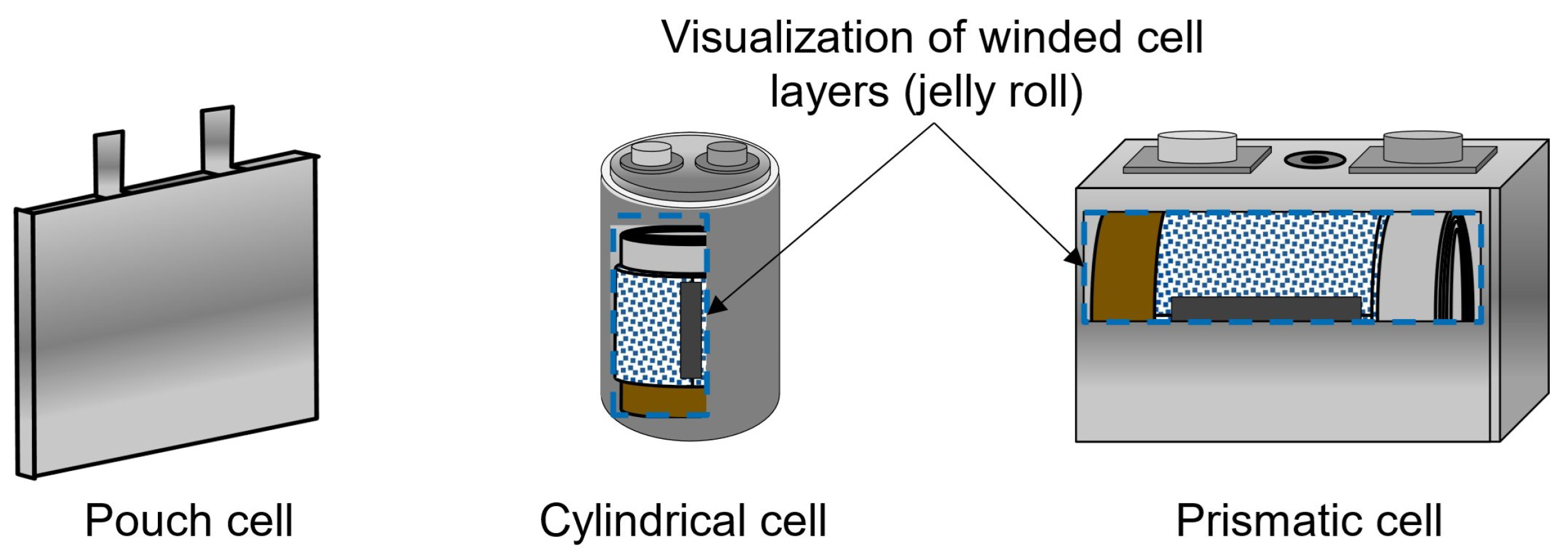
The increased usage of lithium-ion batteries as energy storage, especially in the automotive sector, has motivated the development of several cost models for battery production. With governments pushing for the electrification of car fleets in the next decade, the production of lithium-ion batteries is expected to expand [1], intensifying the need for optimal production chains. Electric vehicle (EV) battery cells are produced in three different formats: cylindrical, prismatic, and pouch [2]. The battery cell is mainly composed of a cathode, an anode, an electrolyte, separators, terminals, and an enclosure case [3]. Figure 1 shows schematics of each of the geometries. Battery pouch cells, cylindrical cells, and prismatic cells differ notably in structure, performance, and application. Pouch cells are lightweight and flexible, but they lack mechanical strength and can swell due to gas generation. Cylindrical cells are robust with consistent structural integrity, are easy to manufacture, and have good thermal management but higher heat generation. Prismatic cells offer higher energy density and fewer connections due to their larger size, making them cost-effective to assemble, but they have direction-dependent mechanical integrity, which can be a structural disadvantage [4]. To compose the battery system of an EV, battery cells are assembled into modules, the modules are assembled into packs, and the packs are built into corresponding EVs. Although the different cell geometries share most of their production steps and have similar compositions, they have significant differences, resulting in different energy densities and production costs; while the cost of individual cells is rarely considered when analyzing EV battery pack prices, it significantly impacts the total cost of a vehicle, since batteries are the key component of EV systems.

Figure 1.
Visualization of the pouch, cylindrical, and prismatic cells.
An EV battery system is responsible for about 25–35% of the total cost of a vehicle [5,6], making it the most prominent individual cost driver of EVs, and making it a component that would benefit from cost improvements; while many battery cell, module, and pack parameters have extensively been analyzed in their cost impact, the literature lacks comparisons and evaluations of different cell geometries and how they influence the final cost of a battery cell. The most complete battery cost and design model, the “Battery Performance and Cost” (BatPac) model of the Argonne National Laboratory [7], allows the user to describe battery packs in detail and to estimate thier production cost per kWh. Their model serves as the backbone of several different studies [8,9,10,11]. However, BatPac performs calculations assuming the battery cells have a stiff pouch construction; consequently, the studies based on it share this same limitation.
Most studies have a varying degree of dependency with BatPaC, either deriving original analyses after using their cell design functionality or basing their cost calculation on BatPac’s cost calculation. Patry et al. [8] uses BatPaC to design cell batteries according to specific configurations. They evaluate the impact of cathode thickness on the cost of the designed cells through an original cost model. Similarly, Yan and Obrovac [9] also use BatPaC to design battery cells, but they then compare them to theoretical K-ion batteries, which are also based on the outputs of the model. On the other hand, Beuse et al. [10] compares the competitiveness between low-cost electricity-storing technologies and lithium-ion batteries. To do so, they base their entire material cost calculation on BatPac, with minor adaptations. Using BatPac in a comparable way, Philippot et al. [11] tries to investigate, among other things, the influence of the production volume and location on the battery cost. They simulate factories with different capacities in several countries and use the cost outputs from BatPac to conduct their analysis.
Some models have tried estimating costs for other battery cell geometries, ignoring the cell format altogether and looking at the battery pack or module level. Ciez and Whitacre [12] made a process-based cost model to examine the cost of manufacturing cylindrical cells. They investigated NCA-G, NMC-G, and LMO-G chemistries, and compared cylindrical and prismatic cells. Orangi and Strømman [13] also created a process-based cost model, but for prismatic cells. Differently from BatPac, their model allows changes in the prices of commodities and describes the costs of labor more precisely. Conversely, Cheng et al. [14] does not mention battery cell geometry and instead analyzes the battery pack cost. Wentker et al. [15] developed a model for pouch cell, but it is independent of and simpler to BatPac. They incorporate the real-time data of cathode active material prices and show that such prices should not be static like BatPac assumes them to be.
In this work, we propose a new cost model with very low dependency on BatPaC that addresses the deficiency in the current literature, which lacks comparisons or tools to compare the cost efficiency of the production of different battery cell geometries. The model uses battery performance inputs to design battery cells in all three common geometries; it also allows for variations in battery frame size, cathode thickness, and cathode composition. The production and material costs are subsequently calculated according to industry standard processes. Both the cell design and cost calculations operate on the battery cell level. This project provides a framework for analyzing and optimizing the economic aspects of battery production, contributing to enhanced decision making and resource allocation in the field.
2. Materials and Methods
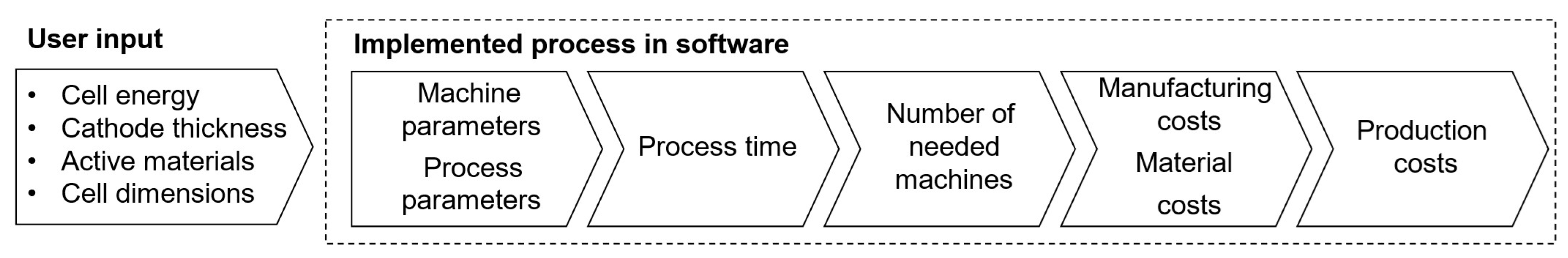
The cost model is divided into two modules: Battery Cell Design and Cost Calculation. The first module is responsible for designing batteries in the three standard geometries, following user-defined performance requirements; the second module calculates the costs of the necessary materials and manufacturing costs. Our cost model is implemented in MATLAB® (Version R2021a), and it facilitates automated and expedited cost estimations compared to traditional, spreadsheet-based models like BatPaC [7]. Figure 2 illustrates the model framework: the user provides battery performance and composition parameters, which are used to design compliant battery cells. Subsequently, using process-specific and facility-wide parameters, the production time for a single battery cell is calculated based on its geometry and design. This enables the calculation of the required machines and facility size, ultimately resulting in the production cost estimation for each designed cell.
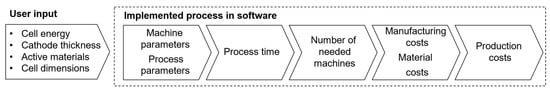
Figure 2.
Battery-cell-specific cost modeling framework.
2.1. Battery Cell Design
The Battery Cell Design module prompts users to input the following information: (i) the desired cell energy in Wh, denoted as ; (ii) the cathode thickness in micrometers, ; (iii) the chosen cathode and anode materials; (iv) the cell dimensions in millimeters. Initially, the module calculates the mass of active material in the cathode using Equation (1), which relates the energy stored in a cell with the product of the cathode mass, the specific capacity of the cathode, and the cathode’s average discharge voltage.
where is the mass of positive active material; and are the specific capacity and average discharge tension of the positive active material—both these values are known and available in the literature. Variables in the model are denoted as , where X represents a physical property and y indicates the associated component, as described in Table 1 and Table 2.

Table 1.
Description of variables for the Battery Cell Design module.
Table 2.
Description of subscripts, y in Table 1, for the Battery Cell Design module.
Next, the module computes the total mass of the cathode by considering the mixing percentages of the cathode components, including the binder and carbon black:
Since electrodes are usually described by their active material and the mixing percentage of other components, the density of the cathode is given by a weighted average of the individual components (Equation (3)). The porosity is also considered in the calculation.
Finally, the density is used to determine the total volume and area of the cathode, as in Equation (4). The volume of the cathode is the ratio between the corresponding mass and density, while the area is given by the ratio between the calculated cathode volume and the user-defined cathode thickness.
where Equations (1)–(4) are valid for all cell geometries, but the following steps in the cell design are different for stacking and winding type cells. Once the total area and volume of the necessary cathode material are known, the Battery Cell Design module calculates how to incorporate it into the battery geometry.
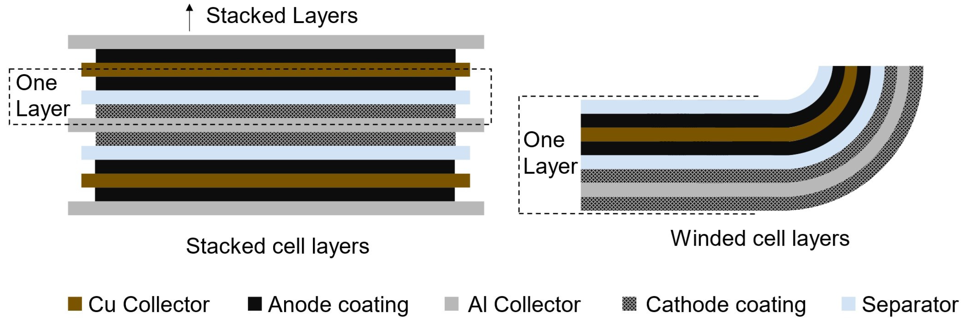
Pouch and prismatic cells are modeled as stacked cell layers, while cylindrical cells are winded (Figure 3). Through the user (iv), the length and height of the cell frame are defined; the missing dimension, the width, is calculated by the Battery Cell Design module. The area of each bi-layer is calculated from the user-defined cell frame dimensions, and the battery cell will have as many bi-layers are necessary to reach the total cathode area and volume, determined in Equation (4). The anode coating in a layer is modeled to be slightly larger than the cathode to guarantee full overlap between the positive and negative active materials: there is an excess length of two mm on each side of the anode (Equation (5)). The internal area of pouch and prismatic cells are calculated differently. The thickness of the seam in pouch cells is substituted by the thickness of the cell can and cell top in prismatic cells.

Figure 3.
Visualization of bi-layers in stacked and winded cells. A stacked bi-cell layer is composed of half a sheet of Cu and Al current collectors, coated with anode and cathode materials, respectively, and separated by a sheet of separator. A winded bi-cell layer includes a full sheet of Cu and Al current collectors, coated on both sides, and two sheets of separator material.
Subsequently, the number of bi-cell layers is calculated by Equation (6). Our model only allows integer layer numbers, taking the next smallest integer (ceil) in case of a fractional result, and adjusting the cell parameters according to the added cathode material. Once the cathode parameters are determined, the relevant anode dimensions are calculated with a linear system (Equation (7)), analogous to Equations (1)–(4). The addition of the N:P term dictates a higher ratio of anode–cathode, guaranteeing the minimum battery performance standards are determined by the positive active material.
For the stacking of bi-cell electrode layers, the thickness of one layer is given by:
which, multiplied by the total number of layers, results in the internal width of the battery cell. The width of the current collectors is divided by two to account for the electrode coating in both sides of the collector.
Cylindrical cells, on the other hand, are modeled as the winding of a long, bi-cell, electrode layer; the user input (iv) is the cell height; the missing dimension, the diameter, is calculated by the Battery Cell Design module. Initially, the electrode lengths are determined from the total cathode area and the internal height of the cell with a system of Equation (9); the two mm anode excess is considered.
Subsequently, the other anode parameters are determined in an analogous manner to stack-type cells through Equation (7). To calculate the resulting diameter, we consider the electrodes to be coiled into an Archimedean spiral, with (Equation (10)) as the distance between loops.
The Battery Cell Design module outputs the complete battery dimensions. For pouch and prismatic cells, the width is calculated based on the user-input length and height. For cylindrical cells, the diameter is calculated based on the user-input height. Additionally, the module calculates all necessary materials to meet the specified performance parameters.
2.2. Cost Calculation
We estimate the production costs of the designed lithium-ion cells using a process-based cost modeling (PBCM), considering industry-standard manufacturing processes for cylindrical, pouch, and prismatic cell formats. The PBCM approach is widely recognized and utilized across various industries to estimate costs in a production chain. Berckmans et al. [16] adopted this methodology to compare the costs of NMC- and silicon-based batteries. Other studies have developed PBCMs focused on specific cell formats: Ciez and Whitacre [12] exclusively analyzed cylindrical cells, while Duffner et al. [17] studied the production of pouch cells.
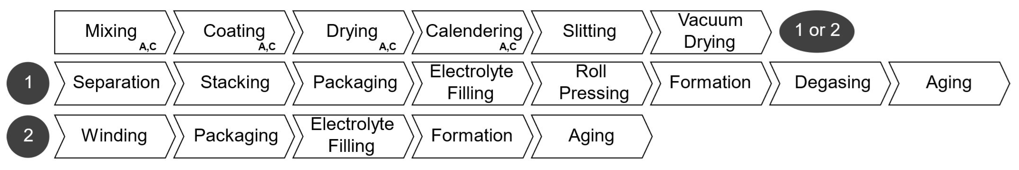
The production steps considered in our PBCM is outlined in Figure 4. The processes from mixing to vacuum drying constitute the electrode manufacturing stage; they are followed by cell-assembly processes, which are different for pouch and prismatic cells, marked with the number one, and for cylindrical cells, marked with number two. The manufacturing cost is calculated summing the labor, energy, equipment, maintenance, building, and overhead costs of each process. The total production cost is the sum of materials and manufacturing cost. Table 3 shows the facility-wide parameters adopted to calculate the costs. Similar to the cell parameter user inputs, these could be altered to represent different scenarios.
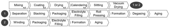
Figure 4.
Steps of battery production.
Table 3.
Facility-wide parameters for the Cost Calculation module.
We estimated the costs of each production step by contacting manufacturers and from proprietary studies conducted at the Chair of Production Engineering of E-Mobility Components at RWTH Aachen University. The estimates are included in Table 4. For the cell-assembly processes, the rates refer to the production of cylindrical cells with a capacity of Wh, and for the stack-type cells, they refer to cells with a capacity of 170 Wh. In the cost model, the process rates are adjusted for the cell capacity according to Equation (11).
where and are the processing time per cell in seconds and the cell capacity in Wh of the reference cell. and represent the same properties but for the designed cell. We adopted a scaling factor of , which represents the cost advantages of producing larger cells. Lastly, the electrode precursor prices, such as lithium, were determined from U.S. Geological Survey [18], converted to EUR. The price of all precursors was considered in the total electrode price. For example, NMC622 is composed of nickel, manganese, and cobalt, aside from lithium. The relative weight of each component contributes to the total price of NMC622 in our model.
Table 4.
Relevant costs and process rate associated with each manufacturing step.
The Cost Calculation module uses facility-wide and process-specific parameters from Table 3 and Table 4, along with battery cell designs from the previous module, to determine the average processing time for a single cell at each manufacturing stage. From this, the cost model calculates the total process time—considering the yearly production of the modeled facility—identifies the required number of machines, and estimates the necessary factory space and resource usage for each manufacturing stage.
2.2.1. Electrode Manufacturing
Electrode production (first line in Figure 4, and first section in Table 4) involves mixing active materials, carbon black, solvent, binder, and additives in proportions determined by the electrode configuration. The resulting slurry is coated onto copper (anode) and aluminum (cathode) foils using slot dies or doctor blades. Coating parameters like thickness, speed, and width are crucial for economic efficiency. The solvent in the slurry must be removed by letting the electrodes dry, often using a float dryer [19]. The subsequent calendering compresses the coated foil to adjust porosity and enhance adhesion. This process is very efficient in terms of costs and has little potential for improvement since it is already mature [20]. At this point, the electrodes are slit into smaller coils, and undergo vacuum drying to remove residual moisture and solvent in an oven for 12 h to 30 h at low temperatures of 60 °C to 150 °C [21].
2.2.2. Cell Assembly
The cell assembly steps differ depending on the cell geometry. For cylindrical cells, after the final drying, in the electrode manufacturing stage, electrode coils are sorted in the following order: anode–separator–cathode–separator. These layers are wound into a cylindrical shape and packed into the cell housing. Cell tabs are welded to contact terminals before sealing. The cell container is, then, filled with electrolyte and sealed a final time. Afterwards, the cells undergo formation, which includes the initial charging and discharging under defined conditions to create the solid electrolyte inter-phase (SEI) [22]. Before being tested and classified, the cells age for up to three weeks while their open-circuit voltage is monitored.
Pouch and prismatic cells have added production steps. Each electrode layer is separated from the electrode coils. The individual sheets are then stacked (anode and cathode alternating with separator sheets in between) into a defined order and stack size. Similar to cylindrical cells, the stacked layers are packed into a solid housing or flexible pouch foil, and filled with electrolyte. Pouch cells are submitted to an optional roll pressing stage to ensure optimum distribution and absorption of the electrolyte. Subsequently, the cells undergo formation and degassing for pouch cells, whereby gas is removed from the pouch. Like cylindrical cells, stacking-type cells are aged before being tested.
2.3. Battery Parameters
The model developed in this paper allows for the design and cost calculation of battery cells of any arbitrary size, composition, and energy capacity. We have selected a set of cell dimensions for each geometry (Table 5), against which the model will be tested. The dimensions are market standards and serve as the industry benchmark. The Battery Cell Design module calculates the undetermined dimensions—the diameter for cylindrical cells and the width for pouch and prismatic cells.
Table 5.
Battery parameters for the Cost Calculation module.
Our selection adopts the widely recognized 18650 cells as the foundational benchmark for the cost assessment of cylindrical cells. Pouch and prismatic cells are less standardized, but their dimensions were selected similarly to cylindrical cells. We based our selection on Link et al. [2], which identified trends in cell dimensions. The cell capacities were also determined from known market values.
The electrodes in lithium-ion cells can be made from various materials and a multitude of combinations. However, the fundamental technological differences lie in the cathode materials used; anode materials are generally standard. The choice of different cell chemistries depends significantly on the application of the battery. Variations can be observed in aspects such as energy density, lifespan, performance, safety, or costs [23]. The most relevant cell chemistries for cathodes include lithium iron phosphate oxide (LFP), lithium manganese oxide (LMO), nickel cobalt aluminum oxide (NCA), and nickel manganese cobalt oxide (NMC).
LFP-based cathodes, with their lower volumetric energy density, are anticipated to be used in buses, trucks, and stationary energy storage systems in the future. Although they exhibit faster self-discharge and lower energy density compared to other types of cathodes, they offer enhanced safety [24]. LMO cathodes are among the more affordable options, as, like LFP, they contain neither nickel nor cobalt. However, their lower capacity often necessitates blending with NMC cathodes. The proportion of LMO in cathodes may decrease in the future as manufacturers strive to extend the range of EVs, a goal often unmet by LMO’s limited capacity alone [25]. NCA cathodes, although considerably more expensive, offer higher capacity, energy density, and longevity [26]. However, their thermal instability presents certain safety risks [27]. Due to these disadvantages, NCA-based cathodes are losing relevance [27,28]. The most commonly used type of cathode is the NMC cathode, which is available in various compositions such as NMC-111, NMC-442, NMC-523, NMC-622, and NMC-811; the trailing numbers indicate the ratio of nickel, manganese, and cobalt [29]. For the analysis of battery production, we compare the main battery cell chemistries: NMC532, NMC 622, NMC 811, NCA, LFP, and LMO.
3. Results and Discussion
We run the cost model for three different scenarios, always using the cell dimensions and electrode thicknesses specified in Table 5. Initially, we consider the batteries described in Table 5, using different cathode materials, to establish a baseline with values commonly found in the industry. We then compare the production costs of cells with different geometries but the same energy capacity. Finally, we analyze how battery capacity influences production cost per kWh for each geometry using an NMC811 cathode.
3.1. Baseline Scenario
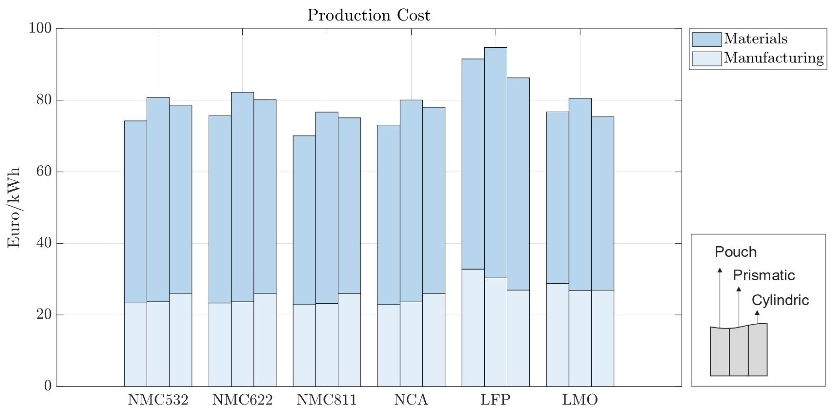
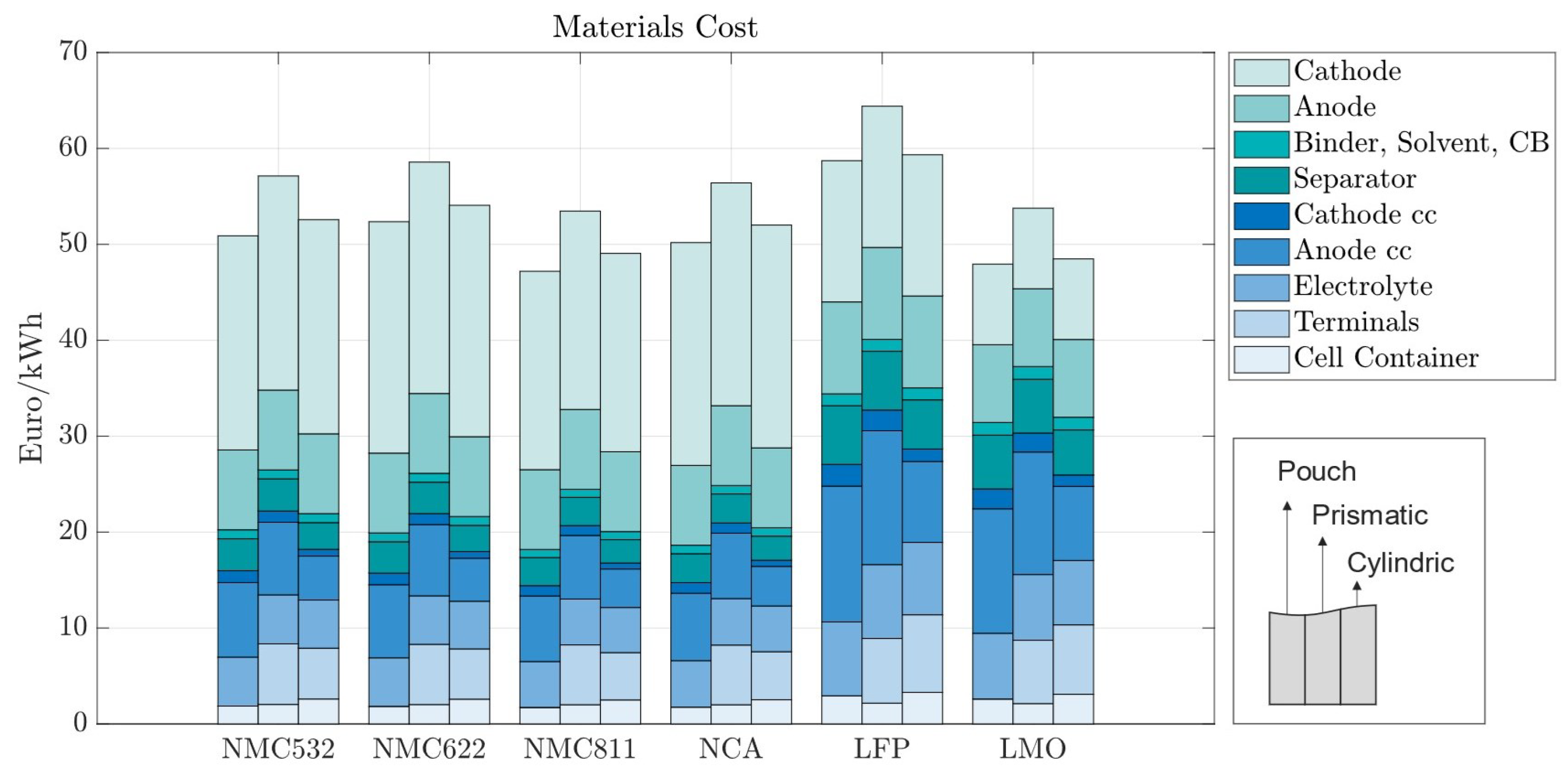
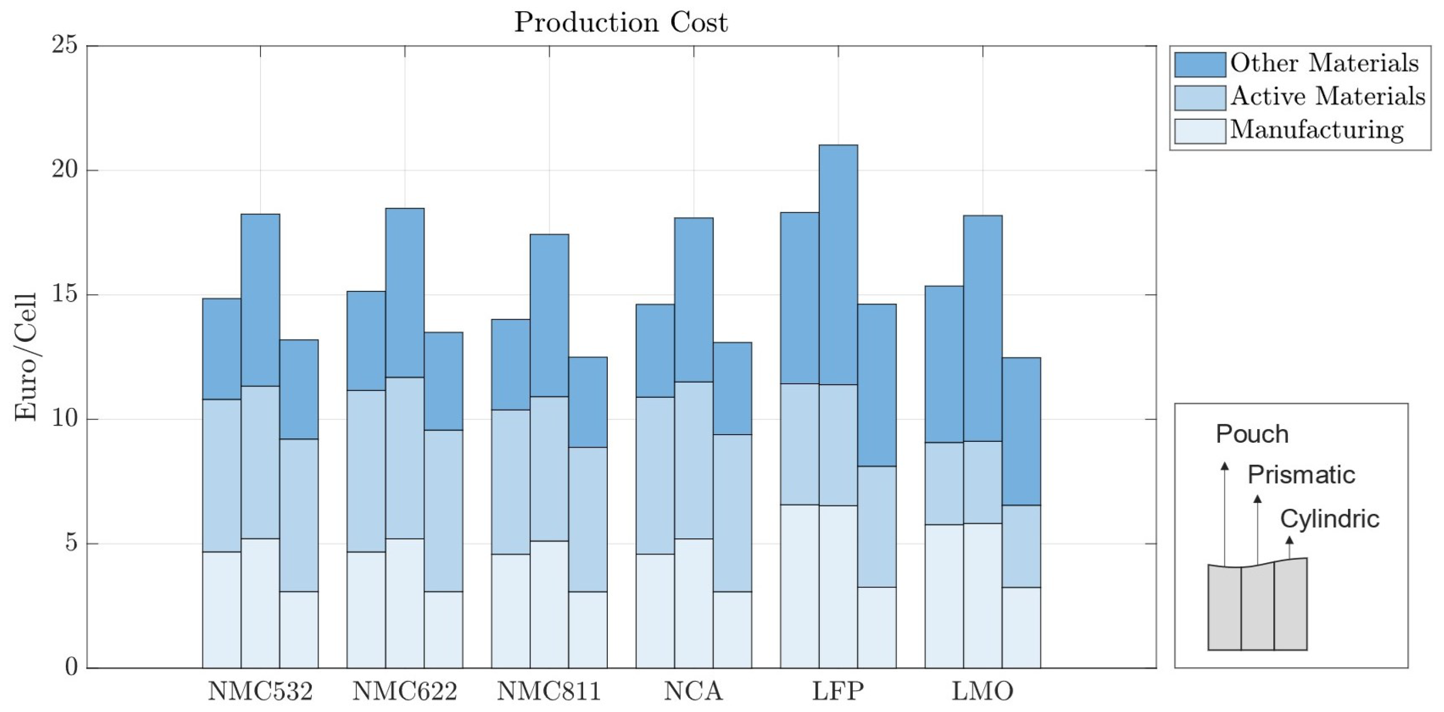
In the baseline scenario, we analyzed the costs of battery cells with 70 m electrodes for pouch, prismatic, and cylindrical battery cells with standard market energy capacities: 12 Wh for cylindrical, 200 Wh for pouch, and 420 Wh for prismatic cells. We find that the prismatic cell is the most expensive cell format independent of cell chemistry (Figure 5). This is mainly due to higher material costs associated with prismatic cells. Figure 6 provides a material cost breakdown, considering all major elements. The cost of terminals is higher in prismatic cells because of the increased number of components used in the cover assembly. The cover assembly of the prismatic cell also requires several connecting elements, increasing the overall costs. Compared to cylindrical cells, stack-type cells require more current collectors in production. For each stacked layer, a small edge of uncoated current collector is needed to connect the cells to one another. This difference is negligible for cathode current collectors, made of aluminum, but becomes noticeable for the anode current collector, made of copper, which is considerably more expensive. As expected, the cost per kWh of the active materials is independent of cell geometry; it depends entirely on the price of each active material and its energy density.
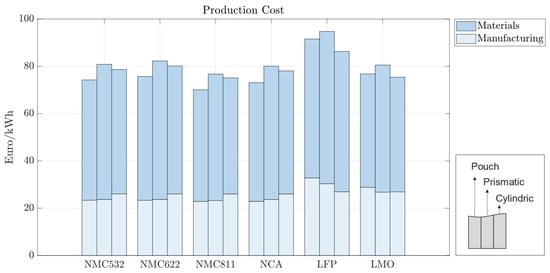
Figure 5.
Production costs per kWh with 70 m electrode coating thickness—270 Wh for pouch cells, 420 Wh for prismatic cells, and 2 Wh for cylindrical cells.
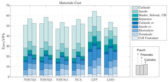
Figure 6.
Material costs per kWh with 70 m electrode coating thickness—270 Wh for pouch cells, 420 Wh for prismatic cells, and 2 Wh for cylindrical cells.
Battery cells utilizing LFP also exhibit higher production costs compared to those employing other active materials such as NMC811; while LFP is a cheaper cathode material, its lower specific capacity requires cells to be bigger in order to accommodate a larger volume of cathode. This causes an increase in manufacturing time, and material usage, contributing to higher overall manufacturing costs. The increase in the production costs for LFP cell chemistry is less pronounced in cylindrical cells, as observed in the Figure 5.
Since cylindrical cells have winded layers, if more active material is needed—as is the case with lower-energy-density cathodes—then the winding time in manufacturing increases. Similarly, stack-type cells require more layers when additional material is needed. However, adding extra layers in the stack-type cells takes more time than winding longer layers, leading to higher machine usage, increased worker time, and overall manufacturing costs of prismatic and pouch cells. Cylindrical cells have a high base manufacturing cost that does not significantly scale with the quantity of active material. In contrast, stack-type cells have a lower base manufacturing cost, which rises as the amount of active material and layers increase. Therefore, cylindrical cells are comparatively more expensive to manufacture with energy-dense cathodes and more cost-effective with less energy-dense cathodes. Moreover, the need for precise control over particle size distribution and coating thickness can further augment production complexities and costs. Overall, while LFP cells may offer certain cost advantages in terms of raw material expenses, other factors, such as energy density and market dynamics, negatively influence the overall cost-effectiveness of LFP vs. NMC cells. In contrast, NMC532, NMC622, NCA, and LMO cells exhibit production costs that lie within a relatively similar range and are positioned between the extremes of LFP and NMC811. This suggests that, while the specific chemistries of the active materials play a significant role in determining production costs, other factors such as electrode design and manufacturing efficiency also exert considerable influence.
In all the battery cells, regardless of chemistry or format, the total cost is dominated by material costs, ranging from 62% to 70% of the production costs per kWh (Figure 6). Material costs are expected to vary between 65 and 80%, representing the major share of battery production costs [30,31]. For batteries using LFP, the material costs are the highest, varying between EUR 58.72 and EUR 64.4/kWh, depending on the cell format; while the LFP cathode material is cheaper, its lower energy density results in larger cells, consuming more of all other materials; the same happens for LMO cathodes. When more energy dense cathodes are used, such as NMC, the cost of cathode materials accounts for as much as 40% of the total material costs due to the high value of lithium, nickel, manganese, and cobalt, despite the lower amounts of active material used.
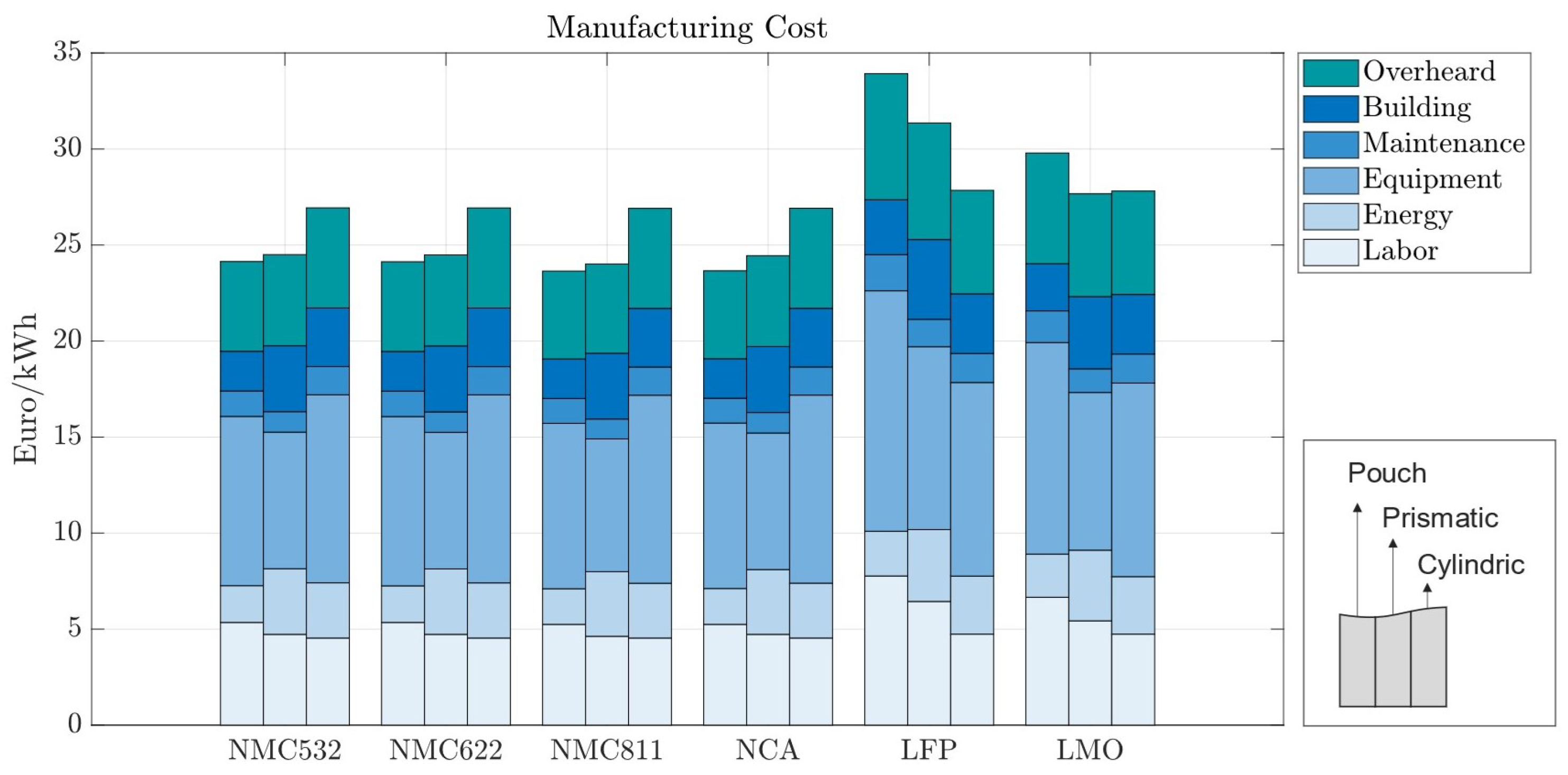
Manufacturing costs come predominantly from equipment costs (Figure 7). Except for LFP and LMO, manufacturing costs across different electrode chemistries do not vary significantly. The main reason for this effect is the lower energy density of those cell chemistries, which causes cells to be bigger and demand more manufacturing time. Material throughput is highly related to the manufacturing process cost, explaining the larger cost shares for battery cells with materials with a lower energy density. Across cell geometries, cylindrical cells result in the highest manufacturing cost for the more energy-dense chemistries and the lowest when low-energy-density cathodes are used.

Figure 7.
Manufacturing costs per kWh with 70 m electrode coating thickness—270 Wh for pouch cells, 420 Wh for prismatic cells, and 2 Wh for cylindrical cells.
3.2. Different Geometries with the Same Capacity
Our cost model is also capable of simulating the production costs of hypothetical digital cells, including those that are currently non-viable in practice. For instance, large-format cylindrical cells are considered impractical due to safety concerns, such as excessive thermal heating. Nevertheless, the cost modeling of such batteries is valuable for comparative analyses across different cell formats and chemistries at a uniform capacity.
We ran the model for cells with the dimensions listed in Table 5, maintaining the same energy capacity of 200 Wh for all geometries. This capacity value was chosen as it is an intermediate value between the industry standards of 12 Wh and 420 Wh. It also allows for the comparison of hypothetical cylindrical and prismatic cells and real pouch cells, all having the same capacity. Figure 8 shows the cost breakdown for the various cell formats and chemistries, all to a capacity of 200 Wh. The y-axis is now given as the price in EUR per cell, and not per kWh, since all cells store the same energy.
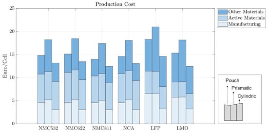
Figure 8.
Manufacturing costs per kWh with 70 m electrode coating thickness for pouch, prismatic, and cylindrical cells with 200 Wh.
Prismatic cells exhibit a higher cost at lower capacities, indicating a slow scaling in price with cell size. This occurs because the cell casing thickness, terminal size, and their associated costs are almost independent of cell size. Consequently, a larger prismatic cell with higher capacity will have its casing and terminal costs spread across a larger energy capacity. The same effect is observed for cylindrical cells, as discussed in Section 3.1, but in the opposite direction; while prismatic cells have lower capacities compared to the baseline scenario, cylindrical cells have higher capacities. The manufacturing costs of winding cylindrical cells scale slowly with cell size, meaning a 200 Wh cell will have a similar cost per kWh as a 12 Wh cell. For this reason, cylindrical cells appear to be the most cost-effective option in Figure 8. However, cylindrical cells with this energy capacity are not currently feasible.
3.3. Influence of Battery Capacity in Production Cost
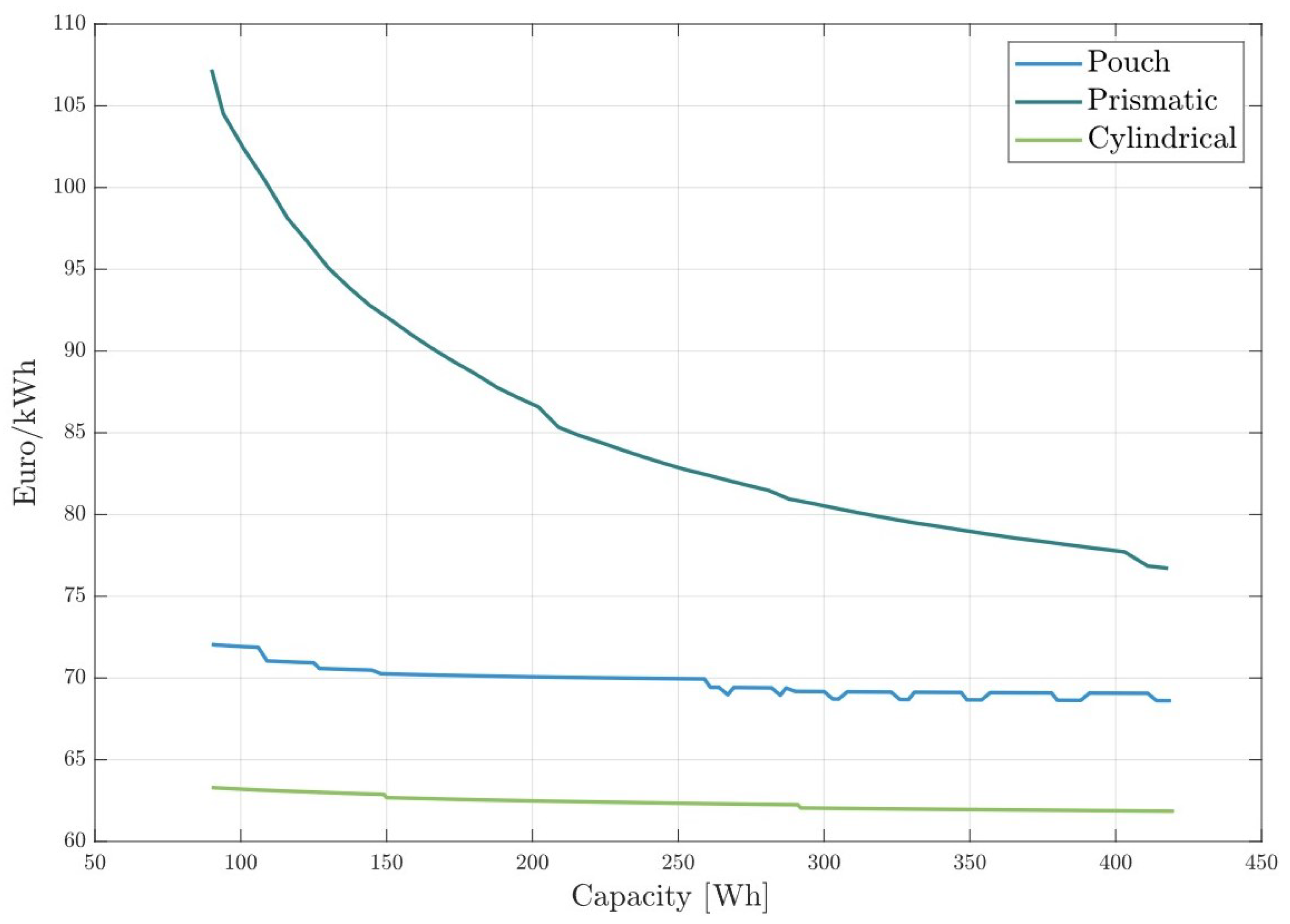
The cost model presented in this paper can also help evaluate how the production cost of each battery cell geometry is affected by battery capacity. We ran the model for batteries with increasing capacities from 90 to 420 Wh for NMC811 cathodes. Figure 9 illustrates the specific production costs for various battery cell formats as a function of battery cell capacity. Prismatic cells show the best cost scaling effect with cell size, reducing costs by 28.3% within the analyzed capacity range. This cost reduction is due to the manufacturing process of the cell housing and terminals. The size and material of the battery terminals are not significantly affected by the cell size. As a result, larger prismatic cells distribute the cost of terminals and housing over more capacity, leading to a lower price per kWh. Although the production costs of prismatic cells can be significantly reduced with increased capacity, they remain the most expensive type of cell, independent of the cell capacity.
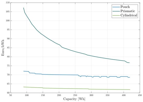
Figure 9.
Specific production costs for battery cells in all cell formats with increasing capacity.
Pouch cells exhibit only moderate scaling with cell capacity, as shown in Figure 9. This moderate scaling occurs because the materials used in pouch cells are largely proportional to the cell size. Consequently, smaller pouch cells have similar material costs per unit of capacity as larger cells. The observed reduction in price per kWh with increasing capacity primarily stems from the more efficient production processes associated with manufacturing larger cells. As the capacity increases, economies of scale in production lead to a slight decrease in specific production costs.
In the capacity range plotted, cylindrical cells are the most cost-efficient. This was already noted in Figure 8, where cells with 200 Wh capacity were analyzed. Cylindrical cells have a high base production cost that does not increase significantly with battery size. For this reason, 12 Wh cells are more expensive per kWh than cells with 100 Wh or more. The winding structure of cylindrical cells allows them to benefit greatly from larger sizes, leading to a reduction in specific production costs as capacity increases.
Discontinuities in the lines are caused by the inefficient usage rates of the machines in the model. In a scenario where 25 h of cathode mixing per day are required to meet the daily production quota, two mixing machines would be needed. However, if only one machine is turned on for just one hour per day, it results in wasted investment and building expenses.
4. Conclusions
This study introduced a novel, comprehensive, process-based cost model that accommodates different geometries of battery cells—cylindrical, prismatic, and pouch. The model leverages user-defined performance inputs to facilitate versatile battery cell design and accurate cost forecasting, a capability lacking in many existing models. By simulating a variety of scenarios, we underscored how cell geometry significantly influences production costs, with prismatic cells consistently emerging as the most expensive due to their complex manufacturing demands.
Our findings highlight the delicate balance between material costs, which predominantly drive total production expenses, and manufacturing complexities, which vary significantly across cell geometries. Notably, the variations in cathode material costs were shown to impact the overall economic feasibility of different cell chemistries, suggesting a nuanced interplay between material selection and production strategy.
The implications of this research extend beyond academic interest, offering valuable insights for industry stakeholders in optimizing production processes and selecting appropriate battery designs to balance cost-effectiveness with performance. Future studies could expand upon this work by integrating more dynamic market variables and exploring the impact of emerging technologies on the economic landscape of battery production. This would further refine the predictive accuracy of our model, supporting the sustainable growth of the EV market in response to evolving industry demands and material innovations.
Author Contributions
Conceptualization, N.S.C. and E.N.; methodology, N.S.C. and E.N.; validation, M.F., H.H. and A.K.; formal analysis, J.S.; investigation, N.S.C. and E.N.; writing—original draft preparation, N.S.C., E.N. and J.S.; writing—review and editing, J.S. and M.F.; visualization, N.S.C. and E.N.; supervision, H.H. and A.K. All authors have read and agreed to the published version of the manuscript.
Funding
This research was funded by German Federal Ministry of Education and Research within the SimBAS project (Grant No. 03XP0338B) and the greenBattNutzung project (Grant No. 03XP0303C), managed by Project Management Jülich.
Data Availability Statement
The original contributions presented in the study are included in the article, further inquiries can be directed to the corresponding authors.
Conflicts of Interest
The authors declare no conflicts of interest.
Abbreviations
The following abbreviations are used in this manuscript:
| EV | electric vehicle |
| PBCM | process-based cost model |
References
- Ding, Y.; Cano, Z.P.; Yu, A.; Lu, J.; Chen, Z. Automotive Li-Ion Batteries: Current Status and Future Perspectives. Electrochem. Energy Rev. 2019, 2, 1–28. [Google Scholar] [CrossRef]
- Link, S.; Neef, C.; Wicke, T. Trends in Automotive Battery Cell Design: A Statistical Analysis of Empirical Data. Batteries 2023, 9, 261. [Google Scholar] [CrossRef]
- Dhameja, S. 1—Electric Vehicle Batteries. In Electric Vehicle Battery Systems; Dhameja, S., Ed.; Newnes: Woburn, MA, USA, 2002; pp. 1–21. [Google Scholar] [CrossRef]
- Hummes, D.N.; Hunt, J.; Hervé, B.B.; Schneider, P.S.; Montanari, P.M. A comparative study of different battery geometries used in electric vehicles. Lat. Am. J. Energy Res. 2023, 10, 94–114. [Google Scholar] [CrossRef]
- Küpper, D.; Kuhlmann, K.; Wolf, S.; Pieper, C.; Xu, G.; Ahmad, J. The Future of Battery Production for Electric Vehicles. Available online: https://www.bcg.com/publications/2018/future-battery-production-electric-vehicles (accessed on 28 November 2023).
- Nykvist, B.; Sprei, F.; Nilsson, M. Assessing the progress toward lower priced long range battery electric vehicles. Energy Policy 2019, 124, 144–155. [Google Scholar] [CrossRef]
- Nelson, P.A.; Gallagher, K.G.; Bloom, I.D.; Dees, D.W. Modeling the Performance and Cost of Lithium-Ion Batteries for Electric-Drive Vehicles, 2nd ed.; No. ANL/CSE-19/2; Argonne National Lab. (ANL): Argonne, IL, USA, 2012. [Google Scholar] [CrossRef]
- Patry, G.; Romagny, A.; Martinet, S.; Froelich, D. Cost modeling of lithium-ion battery cells for automotive applications. Energy Sci. Eng. 2014, 3, 71–82. [Google Scholar] [CrossRef]
- Yan, Z.; Obrovac, M. Quantifying the cost effectiveness of non-aqueous potassium-ion batteries. J. Power Sources 2020, 464, 228228. [Google Scholar] [CrossRef]
- Beuse, M.; Steffen, B.; Schmidt, T.S. Projecting the Competition between Energy-Storage Technologies in the Electricity Sector. Joule 2020, 4, 2162–2184. [Google Scholar] [CrossRef]
- Philippot, M.; Alvarez, G.; Ayerbe, E.; Van Mierlo, J.; Messagie, M. Eco-Efficiency of a Lithium-Ion Battery for Electric Vehicles: Influence of Manufacturing Country and Commodity Prices on GHG Emissions and Costs. Batteries 2019, 5, 23. [Google Scholar] [CrossRef]
- Ciez, R.E.; Whitacre, J. Comparison between cylindrical and prismatic lithium-ion cell costs using a process based cost model. J. Power Sources 2017, 340, 273–281. [Google Scholar] [CrossRef]
- Orangi, S.; Strømman, A.H. A Techno-Economic Model for Benchmarking the Production Cost of Lithium-Ion Battery Cells. Batteries 2022, 8, 83. [Google Scholar] [CrossRef]
- Cheng, Y.; Porpora, F.; D’Arpino, M.; Rizzoni, G. Cost analysis in different battery pack architectures considering protection, monitoring, and diagnostics. In Proceedings of the 2021 IEEE Transportation Electrification Conference & Expo (ITEC), Chicago, IL, USA, 21–25 June 2021; pp. 832–839. [Google Scholar] [CrossRef]
- Wentker, M.; Greenwood, M.; Leker, J. A Bottom-Up Approach to Lithium-Ion Battery Cost Modeling with a Focus on Cathode Active Materials. Energies 2019, 12, 504. [Google Scholar] [CrossRef]
- Berckmans, G.; Messagie, M.; Smekens, J.; Omar, N.; Vanhaverbeke, L.; Van Mierlo, J. Cost projection of state of the art lithium-ion batteries for electric vehicles up to 2030. Energies 2017, 10, 1314. [Google Scholar] [CrossRef]
- Duffner, F.; Mauler, L.; Wentker, M.; Leker, J.; Winter, M. Large-scale automotive battery cell manufacturing: Analyzing strategic and operational effects on manufacturing costs. Int. J. Prod. Econ. 2021, 232, 107982. [Google Scholar] [CrossRef]
- U.S. Geological Survey. Mineral Commodity Summaries 2024; Technical Report; U.S. Geological Survey: Menlo Park, CA, USA, 2024. [Google Scholar] [CrossRef]
- Kwade, A.; Haselrieder, W.; Leithoff, R.; Modlinger, A.; Dietrich, F.; Droeder, K. Current status and challenges for automotive battery production technologies. Nat. Energy 2018, 3, 290–300. [Google Scholar] [CrossRef]
- Liu, Y.; Zhang, R.; Wang, J.; Wang, Y. Current and future lithium-ion battery manufacturing. IScience 2021, 24, 102332. [Google Scholar] [CrossRef] [PubMed]
- Warner, J.T. The Handbook of Lithium-Ion Battery Pack Design: Chemistry, Components, Types and Terminology; Elsevier: Amsterdam, The Netherlands, 2015. [Google Scholar]
- Phul, S.; Deshpande, A.; Krishnamurthy, B. A mathematical model to study the effect of potential drop across the SEI layer on the capacity fading of a lithium ion battery. Electrochim. Acta 2015, 164, 281–287. [Google Scholar] [CrossRef]
- Nicke, K.; Holst, G.; Gleiter, T.; Reichelt, L.; Zittel, W. Batterierecycling als Beschäftigungs perspektive für die Lausitz. In Ansätze Einer Arbeits-Und Beschäftigungsorientierten Regionalentwicklungsstrategie; IMU Institut: Stuttgart, Germany, 2019. [Google Scholar]
- Windisch-Kern, S.; Holzer, A.; Ponak, C.; Nagovnak, P.; Raupenstrauch, H. Recycling von Lithium-Ionen-Batterien: Herausforderungen und aktuelle Forschungsergebnisse. BHM 2021, 166, 150–156. [Google Scholar] [CrossRef]
- Inclán, I.R. Analysis of Global Battery Production: Production Locations and Quantities of Cells with LFP and NMC/NCA Cathode Material; Fraunhofer Institute for Systems and Innovation Research ISI: Stuttgart, Germany, 2023. [Google Scholar]
- Tang, Z.; Feng, D.; Xu, Y.; Chen, L.; Zhang, X.; Ma, Q. Safety Issues of Layered Nickel-Based Cathode Materials for Lithium-Ion Batteries: Origin, Strategies and Prospects. Batteries 2023, 9, 156. [Google Scholar] [CrossRef]
- Ohneseit, S.; Finster, P.; Floras, C.; Lubenau, N.; Uhlmann, N.; Seifert, H.J.; Ziebert, C. Thermal and Mechanical Safety Assessment of Type 21700 Lithium-Ion Batteries with NMC, NCA and LFP Cathodes–Investigation of Cell Abuse by Means of Accelerating Rate Calorimetry (ARC). Batteries 2023, 9, 237. [Google Scholar] [CrossRef]
- Lu, S.J.; Tang, L.B.; Wei, H.X.; Huang, Y.D.; Yan, C.; He, Z.J.; Li, Y.J.; Mao, J.; Dai, K.; Zheng, J.C. Single-crystal nickel-based cathodes: Fundamentals and recent advances. Electrochem. Energy Rev. 2022, 5, 15. [Google Scholar] [CrossRef]
- Vekić, N. Lithium-Ionen-Batterien für die Elektromobilität: Status, Zukunftsperspektiven, Recycling. Thinktank Ind. Ressourcenstrategien 2020, 9, 2022. [Google Scholar]
- Degen, F.; Krätzig, O. Modeling large-scale manufacturing of lithium-ion battery cells: Impact of new technologies on production economics. IEEE Trans. Eng. Manag. 2023, 71, 6753–6769. [Google Scholar] [CrossRef]
- Qi, L.; Wang, Y.; Kong, L.; Yi, M.; Song, J.; Hao, D.; Zhou, X.; Zhang, Z.; Yan, J. Manufacturing processes and recycling technology of automotive lithium-ion battery: A review. J. Energy Storage 2023, 67, 107533. [Google Scholar] [CrossRef]
Disclaimer/Publisher’s Note: The statements, opinions and data contained in all publications are solely those of the individual author(s) and contributor(s) and not of MDPI and/or the editor(s). MDPI and/or the editor(s) disclaim responsibility for any injury to people or property resulting from any ideas, methods, instructions or products referred to in the content. |
© 2024 by the authors. Licensee MDPI, Basel, Switzerland. This article is an open access article distributed under the terms and conditions of the Creative Commons Attribution (CC BY) license (https://creativecommons.org/licenses/by/4.0/).