Abstract
With the increasing demand for Li resources worldwide, the easy recycling of Li-ion batteries materials becomes essential. We report a binder-free cathode consisting of carbon nanotubes (CNTs) and LiFePO4 (LFP) nanoparticles embedded in a 3D Al network. The electrode stability depends on the CNT ratio, where 3% CNT-wrapping LFPs provide a stable structure free of detachment from Al foam, as observed on Al foil. The binder-free cathode sheet exhibited excellent performance for high-rate discharge and long-term cycle life. Materials on the cathode can be easily detached with ultrasonic treatment when immersed in organic solvent, which is advantageous for a green and high-efficiency strategy of recycling all valuable materials compared to the binder-used electrode.
1. Introduction
The development of the secondary Li-ion battery (LIB) industry directly leads to an application burst of electrical vehicles worldwide, contributing to clean technology for carbon neutrality [1,2,3,4]. However, the huge demand of Li-based cathode materials increases the Li supply pressure, considering that the reserve of the Li element on Earth is actually low compared to other elements (Al, Si, Fe, etc.) [5,6]. The shortage of Li compounds brings very unstable Li prices, which is unhealthy to the development of the industry. In turn, this stresses the importance of recycling Li resources from spent LIBs [7,8,9,10].
In general, for LIB fabrication, binders are used in large amounts to adhere Li cathode materials tightly onto the Al foil (current collector). This tight interaction ensures the close contact of the cathode materials with the current collector, for electronic transfer and for long-term stability [11,12]. But such structure result in a high difficulty in recycling Li resources from spent batteries. Up to now, although various methods (wet chemistry and high-temperature melting) have been proposed for recycling Li inside LIBs [13,14,15,16], most of them are destructive to the battery structure. And the separation of various complicated and even toxic components of LIBs from each other is still costly and sometimes full of risk.
In the present work, we propose a new concept for fabricating a binder-free cathode with 3D Al foam (current collector) to fix the cathode materials. In detail, in using LiFePO4 (LFP) nanoparticles to model the cathode material, they were firstly mixed with carbon nanotubes (CNTs) to form a composite slurry, and then used to fill the pores of the Al foam, following the compression procedure. LIBs with such configuration work well for charging and discharging to deliver a high performance. The contact between the LFP nanoparticles with the CNTs was good, where 1D CNTs wrapped the LFP nanoparticles tightly owing to the strong interaction of the van der Waals forces between the two kinds of nanoparticles [17,18,19,20]. And the contact between the composite powder and numerous Al wires, which composed the uniform 3D network, was also excellent based on the mechanical compression [21,22,23]. In considering the recycling of LFP materials, the cathode sheets of spent LIBs were immersed in organic solutions. The assisted external ultrasonic operation enabled the easy detachment of CNTs and LFP powders from the Al foam network. Most of the CNTs and LFP could be extracted from the cathode and transferred to solution under ultrasonic conditions. The present strategies may offer new options for the field.
2. Materials and Methods
2.1. Material Preparation
CNTs prepared with the chemical vapor deposition (CVD) method had a diameter range of 7–11 nm and length of several micrometers [24,25,26,27]. After purification with acidic washing and high-temperature vacuum treatment, their purity met the requirements of the LIB industry. LFP nanoparticles (purchased from Pulead Technology Industry Co., Ltd., Beijing, China) had a particle size of 100 nm, which had a thin carbon layer on the external surface. Al foam was prepared with magnetically controlled spouting Al particles on porous polyurethane (PU) foam from the Al target, followed with the removal of the PU template through controlled oxidation below 600 °C [21,22]. The pristine Al foam used here was 1 mm thick, 50 cm long, and 20 cm wide. Its porosity, mass density, and Al purity were 95%, 120 g m−2, and 99.995%, respectively.
2.2. Cathode Sheet Fabrication
Firstly, LFP nanoparticles, CNTs, and conductive carbon black (Super P) were mixed in an N-methyl-2-pyrrolidone (NMP) solution and stirred in a homogenizer (SK-300II, Kakuhunter Co., Ltd., Shiga Prefecture, Japan) for 2 h. The viscosity of the slurry was controlled at 1500–3000 mPa·s. Secondly, 3D Al foam was immersed into the slurry to sufficiently absorb the LFP and CNT mixture inside. Then, the cathode sheet was dried at 70 °C for 2 h to remove all NMP, following roll compression by a rolling machine (MSK-2150, MTI Corporation, Richmond, CA, USA).
Three binder-free cathodes with different compositions (1% CNTs + 94% LFP, 3% CNTs + 92% LFP, and 5% CNTs + 90% LFP, where the mass fraction of Super P was controlled at 5%) were prepared and compared, which were marked as 1% CNTs, 3% CNTs and 5% CNTs, respectively. These cathode sheets were die-cut to a size of 5 cm wide, 7.6 cm long, and 190 μm thick. The mass loading and compaction density of active materials in the cathode sheets were 22 mg cm−2 and 1.16 g cm−3.
2.3. Anode Sheet and Pouch Cell Fabrication
An anode sheet was directly purchased from Guangdong Canrd New Energy Technology Co., Ltd. (Guangzhou, China). It was a typically fast-charging graphite anode adhered onto a Cu foil (current collector). The N/P ratio was controlled at 1.10.
To fabricate a pouch cell, 5 cathode sheets and 6 anode sheets were stacked with polypropylene (PP) membrane (20 μm thick) one by one and sealed with an Al plastic film. The space inside the electrodes and pouch cell was filled with LiPF6-based electrolyte, which was purchased from Zhangjiagang Guotai Huarong New Chemical Materials Co., Ltd. (Suzhou, China) (LB-4927BY). The areal capacity and total capacity of the pouch cell were about 3.05 mAh cm−2 and 580 mAh.
2.4. Electrochemical Test
Charge and discharge tests on the pouch cell were performed using a battery testing system (CT6002A, Wuhan Land Electronics Co., Ltd., Wuhan, China) at 25 °C. During the initial formation process, the fresh pouch cell was firstly charged at 0.05 C for 2 h and then charged at 0.1 C for 5 h, followed by being charged to 3.8 V at 0.2 C and discharged to 2.4 V at 0.2 C to finish the first charge–discharge cycle. It was then charged and discharged at 0.2 C for 3 cycles in a voltage range of 2.4–3.8 V, including a constant-voltage charge process at 3.8 V until a cut-off current rate of 0.02 C. During the rate tests, the pouch cell was charged at 1 C (including the constant-voltage charge process) and discharged at rates from 1 C to 20 C (constant-current mode). A cyclic test was performed by charging and discharging the pouch cell at 1 C. The specific capacity (mAh g−1) was calculated using the discharge capacity and the total mass of the LFP in the cathodes. The energy density (E, Wh kg−1) and average power density (P, W kg−1) were calculated using the following equations:
Here, I is the discharge current (A), U is voltage (V), t is discharge time (s), and m (kg) is the total mass of active materials (LFP and graphite) in the cathode and anode.
3. Results and Discussion
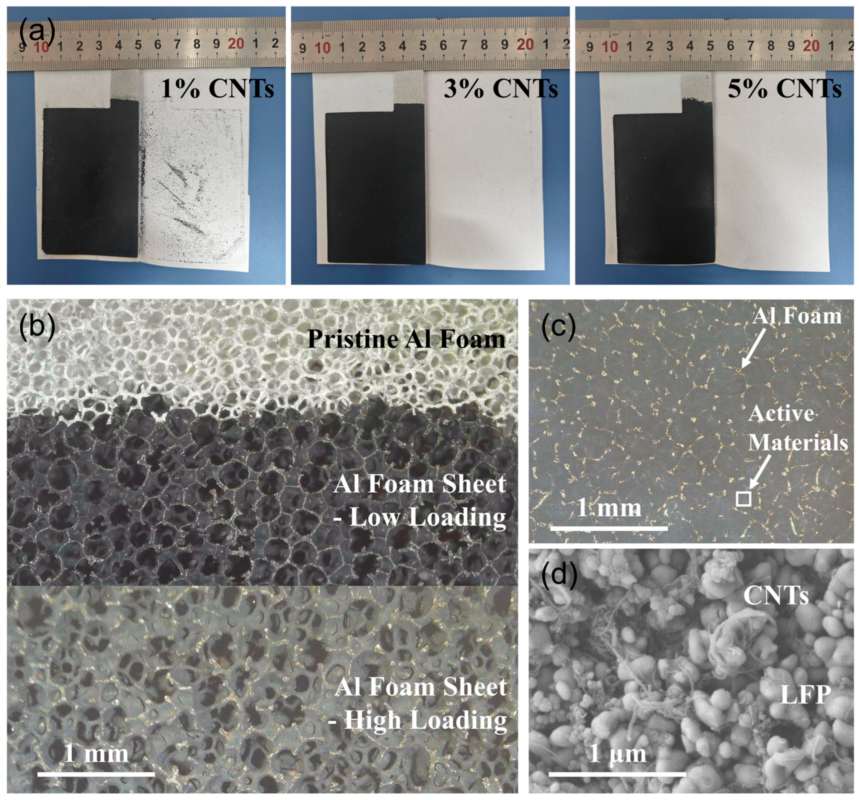
Figure S1 shows scanning electron microscope (SEM) images of the LFP nanoparticles and transmission electron microscope (TEM) images of the CNT powders. The particle size of the LFP nanoparticles was about 100 nm, and the diameter of the CNTs was about 10 nm with walls of about 15 layers. When these materials were mixed into binder-free slurry and coated on conventional Al foil, a severe delamination of the coating occurred after drying due to inadequate adhesion. In contrast, the 3D skeleton structure of the Al foam can provide excellent support for the active materials, forming a stable binder-free cathode (Figure S2). Further, we placed three Al foam-based binder-free cathodes in the middle of a folded white paper, ensuring tight contact, and then observed the delamination of the coatings. As shown in Figure 1a, some delamination of coating materials occurred in the 1% CNT cathode, whereas no such phenomenon was seen in the other two cathodes, proving the important adhesive effect of CNTs. The micrograph in Figure 1b shows that pristine Al foam was constructed from lots of interconnected and interlaced Al wires, exhibiting a 3D porous structure with pore diameters in the range of several hundred micrometers. When the slurry was coated on Al foam without compression, cathode materials were primarily filled within the pores of the Al foam under a low-loading condition. While increasing the loading, a small portion of the coatings can also be supported on the surface of Al wires. After roll compression, most of the active materials are squeezed into the internal pores of the cathode, resulting in an extremely flat surface (Figure 1c). In addition, the Al wires interconnected to form a 3D conductive network and support structure, in tight contact with the active materials. As shown in Figure 1d, the CNTs were wrapped around the LFP nanoparticles uniformly on a microscopic scale. This interaction through van der Waals forces is tight to ensure that the external layer interacts with the inner layer tightly. In summary, Al wires form a continuous network to fix LFP and CNT particles on a macroscopic scale, and the CNTs are also wrapped around the LFP through the strong interaction at a microscopic scale, which are the key effects of avoiding the detachment of LFP nanoparticles from the matrix.

Figure 1.
(a) Optical images of the binder-free cathodes of CNTs-LiFePO4-Al foam with three compositions. The coating materials in the 1% CNT cathode exhibited delamination after compression within a folded white paper, which was not observed in the other two cathodes. (b) Optical micrograph of pristine Al foam and Al foam-based binder-free cathode with low and high loading of active materials (3% CNTs, uncompressed). (c) Optical micrograph of Al foam-based binder-free cathode (3% CNTs, compressed); the golden wires are Al foam, and the black regions are active materials. (d) Enlarged SEM image of the white region in (c).
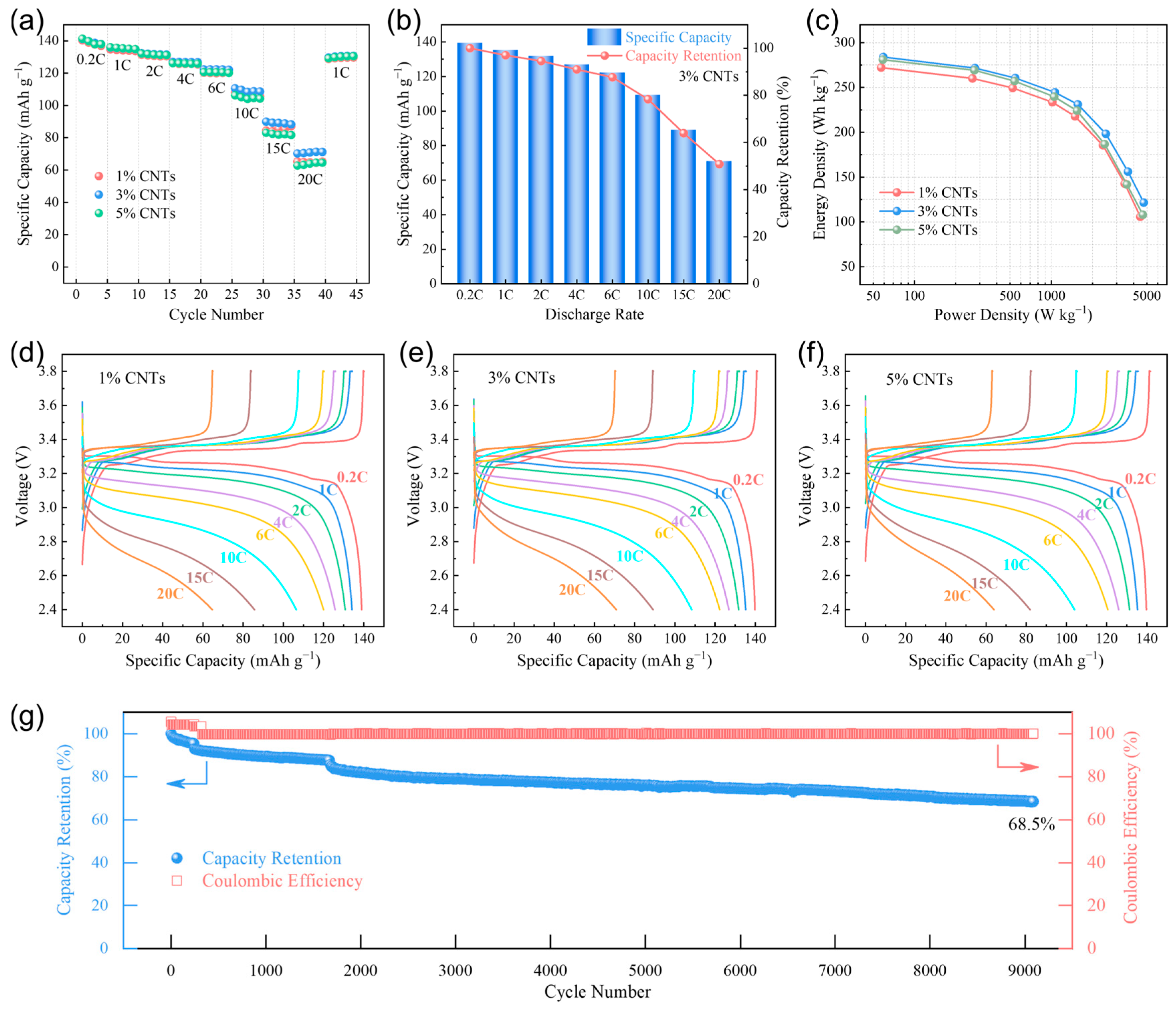
The electrochemical performances of the pouch cells with three binder-free cathodes of CNTs-LiFePO4-Al foam were tested to verify the availability and superiority of the strategy proposed in this work. The specific capacities at different discharge rates in Figure 2a show that the three cathodes had similar performances at 0.2 C–6 C, and the 3% CNT cathode had the most superior performance at a high rate of 10 C–20 C. To explain the optimal 3% CNT content, we measured the tap density of the LFP and CNTs powders used in this work, which were about 0.9 g cm−3 and 0.035 g cm−3. Accordingly, the volume ratio of the LFP to CNTs in the cathodes of 1% CNTs (94% LFP + 1% CNTs), 3% CNTs (92% LFP + 3% CNTs), and 5% CNTs (90% LFP + 5% CNTs) could be determined as 3.66, 1.19, and 0.70, respectively. The volume fraction of CNTs increased with the rise in their content, and the volume ratio in the 3% CNT cathode was closest to 1. For 1% CNTs, insufficient conductivity and adhesion (Figure 1a) may be the reasons for the relatively lower specific capacity at high discharge rates. For 5% CNTs, an excessive content of CNTs would lead to poor dispersion and severe spontaneous aggregation (Figure S3), which diminished the improvement effect on the conductivity of LFP. It may even hinder the Li-ion diffusion of LFP particles, thereby reducing the specific capacity at high discharge rates. Overall, the 3% CNT cathode exhibited the best rate performance among these binder-free cathodes. It can withstand a discharge rate as high as 20 C, with specific capacities at 4 C/10 C/20 C being 127 mAh g−1, 109 mAh g−1, and 71 mAh g−1, and the corresponding capacity retention (compared to 0.2 C) reaching 91%, 78%, and 51%, where the values always remained at a high level (Figure 2b). These results indicate that the CNTs-Al foam-assisted binder-free cathode showed extremely excellent electrochemical performance.
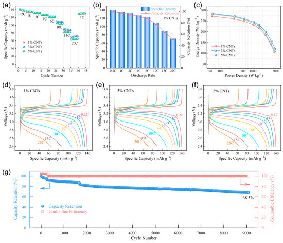
Figure 2.
(a) Specific capacity of the binder-free cathodes of CNTs-LiFePO4-Al foam at different discharge rates. (b) Capacity retention of the binder-free cathode with 3% CNTs at different discharge rates compared to 0.2 C. (c) Energy density and power density (Ragone plot) of the pouch cells with binder-free cathodes. (d) Voltage–capacity plot of the binder-free cathode with 1% CNTs. (e) Voltage–capacity plot of the binder-free cathode with 3% CNTs. (f) Voltage–capacity plot of the binder-free cathode with 5% CNTs. (g) Cycle performance of the binder-free cathode with 3% CNTs.
Based on the total mass of active materials (LFP and graphite) in the cathode and anode, we calculated the energy density and average power density of the three pouch cells with binder-free cathodes (Figure 2c). Similarly, 3% CNTs exhibited the most outstanding performance. The energy density of 3% CNTs could reach 284 Wh kg−1 at a power density of 59 W kg−1, and it remained at 245 Wh kg−1 at 1064 W kg−1 and 121 Wh kg−1 at 4739 W kg−1. As shown in Figure 2d–f and Figure S4, the three pouch cells exhibited well charge–discharge characteristics at all rates. Within the discharge rates of 0.2 C–6 C, the voltage polarization did not significantly increase, demonstrating the typical characteristic of LFP materials with a voltage plateau. Even at high discharge rates of 10 C–20 C, all three binder-free cathodes still possessed a high specific capacity and high discharge voltage. Specifically, the median voltages of 3% CNTs while discharging at 0.2 C, 2 C, 6 C, 10 C, and 20 C were 3.259 V, 3.180 V, 3.048 V, 2.922 V, and 2.725 V, respectively, always higher than that of 1% CNTs (3.258 V, 3.173 V, 3.023 V, 2.891 V, and 2.671 V) and 5% CNTs (3.258 V, 3.172 V, 3.024 V, 2.885 V, and 2.704 V), again demonstrating the best discharge performance of 3% CNTs among these binder-free cathodes. Furthermore, we also performed the cyclic test at 1 C charge–discharge using the pouch cell with the binder-free cathode of 3% CNTs. Figure 2g shows that the coulombic efficiency was stable at near 100%, with the discharge capacity slowly decreasing as the cycle number increased. Specifically, the capacity retention after 2000, 5000, and 9000 cycles was 82%, 76%, and 69%, respectively. These electrochemical test results confirm that the Li-ion batteries with a binder-free cathode of CNTs-LiFePO4-Al foam possessed remarkable rate performance and cycle performance, which we attribute to three key factors. Firstly, the strong interaction between CNTs and LFP, along with an appropriate volume ratio and the supporting effect of Al foam with a 3D skeleton, confer good stability to the cathode, enabling it to withstand high-current impacts and maintaining a stable electrode structure over long cycles. Secondly, the CNTs and Al foam effectively enhanced the electronic conductivity within the cathode coatings and between the coatings and current collector at microscopic and macroscopic scales, allowing for small polarization and high capacity even at very high discharge rates. Furthermore, the porous structure of the CNTs and Al foam facilitate electrolyte seepage, which is beneficial for improving Li-ion diffusion performance and ensuring sufficient ion supply over extended cycling periods [21,23]. These performances of the present binder-free cathode of CNTs-LiFePO4-Al foam are comparable or superior to those of other binder-free electrodes [28,29,30,31,32,33], proving that it is a simple but advanced strategy for fabricating a binder-free cathode using Al foam and CNTs. As for the fast-charging aspect, we believe that it is more closely related to the anode performance (such as anionic activity regulation, solid electrolyte interphase modification, anodic kinetic enhancement, etc.) [34,35,36], which was not deeply investigated in this study.
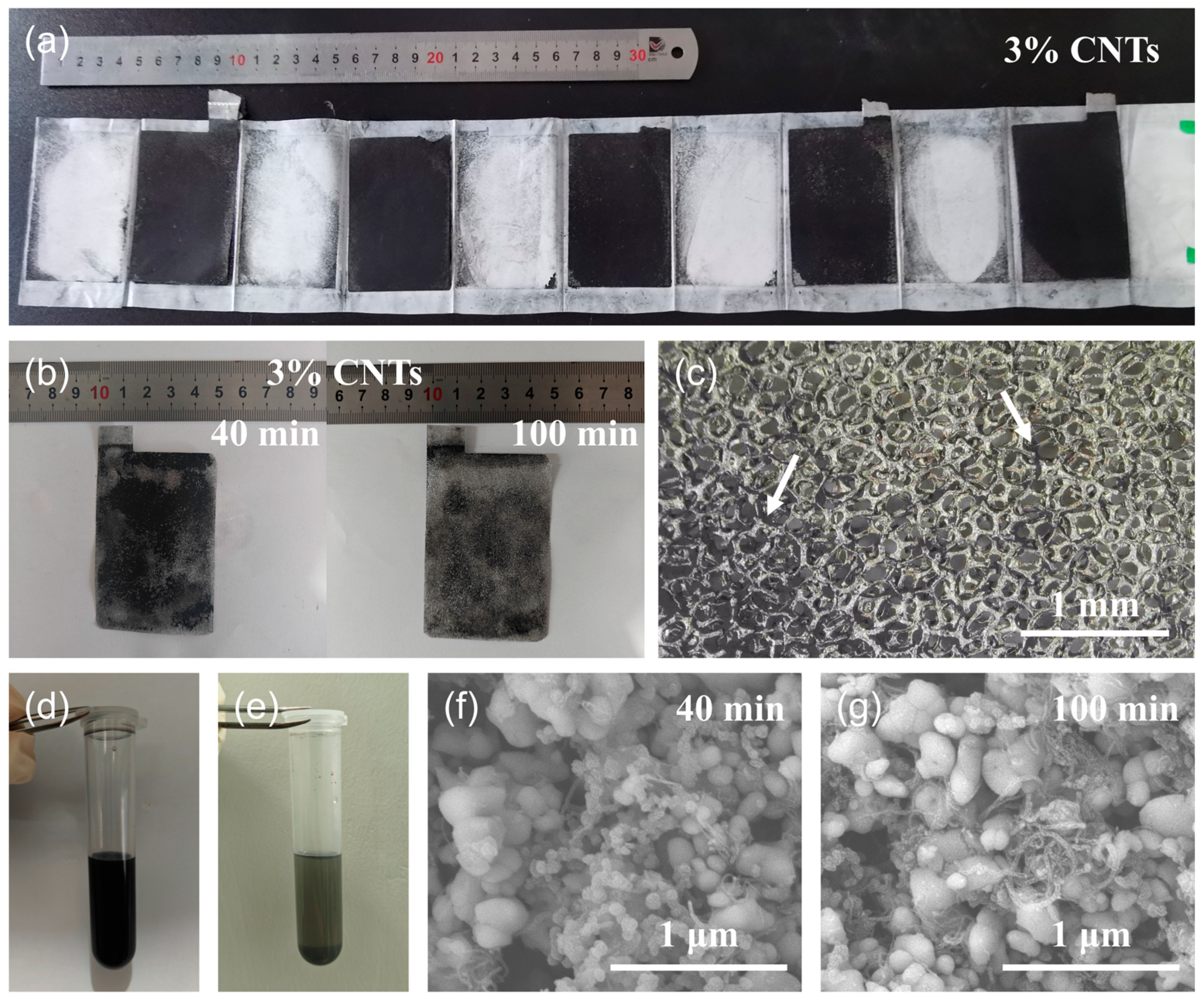
After the discharge test, the pouch cell with the binder-free cathode was treated to recycle Li compounds. Figure 3a shows disassembled binder-free cathode sheets with 3% CNTs. There was little black cathode material detachment on the PP membrane, indicating that the supporting effect of the CNTs and Al foam remained stable even after high-rate discharge. Further, the binder-free cathode was immersed into NMP solvent and subjected to ultrasonic treatment. It can be clearly seen in Figure 3b that the black powders were detached from the Al foam and some regions of silver-white Al foam occurred after ultrasonication for 40 min. When increasing the ultrasonic time to 100 min, the black areas (cathode material coating) became lighter in color, while the silver-white areas (Al foam) became larger, indicating that more cathode materials could be detached as ultrasonic time increased. The micrograph in Figure 3c reveals that most of the cathode materials had been detached in the NMP solvent with only a little residual on the Al wires (as the arrows mark) after ultrasonic treatment for 100 min. Meanwhile, the NMP solvent in the beaker bottle became very black. The same procedure of ultrasonic treatment was conducted for the binder-free cathode of 5% CNTs (Figure S5). However, there was still lots of black powder residual on the Al foam cathode after ultrasonic for 100 min. This difference indicates that excessive CNTs may lead to excessive adhesion, making it difficult for active materials in spent LIBs to detach from Al foam, thus complicating the recycling process of Li compounds.

Figure 3.
(a) Optical image of the disassembled binder-free cathode sheets with 3% CNTs. (b) Optical images of the binder-free cathode with 3% CNTs after ultrasonic treatment for 40 min and 100 min. (c) Optical micrograph of the binder-free cathode with 3% CNTs after ultrasonic treatment for 100 min. (d) The NMP suspension with 100 min ultrasonication. (e) The solution in (d) after standing vertically for 12 h. (f) SEM image of solid materials in the suspension with 40 min ultrasonication. (g) SEM image of solid materials in the suspension with 100 min ultrasonication.
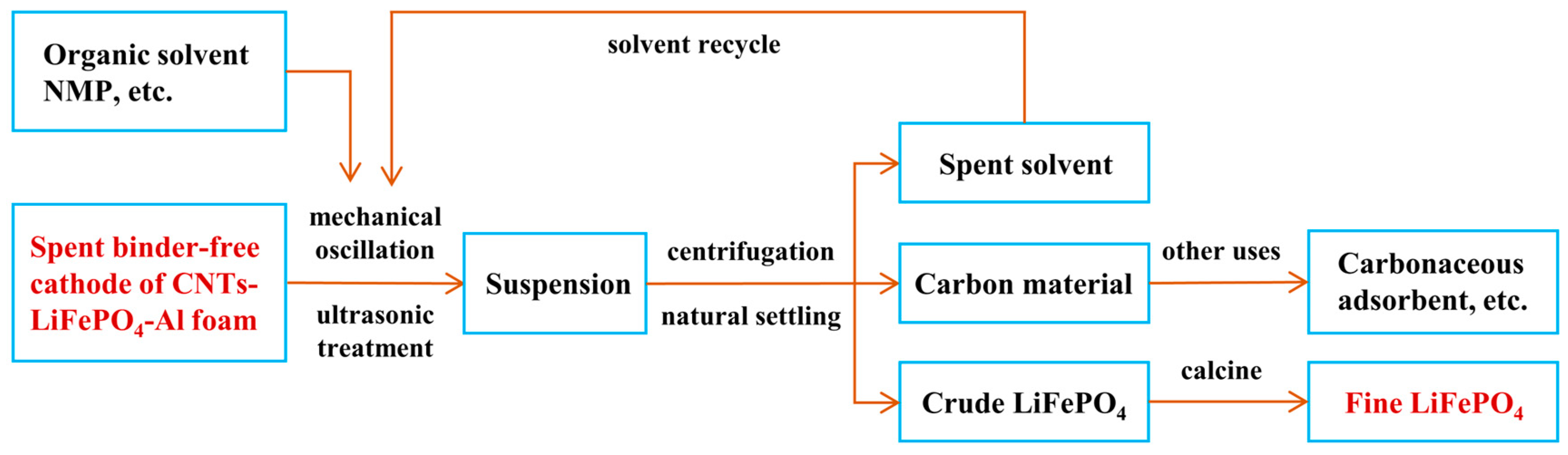
In order to validate the feasibility of recycling LFP nanoparticles from the binder-free cathode of CNTs-LiFePO4-Al foam, we transferred a portion of NMP suspension after 100 min of ultrasonication into a centrifuge tube, which at this point was uniformly dark black (Figure 3d). After standing the tube vertically for 12 h, it was observed that almost all the solids in the solution naturally settled at the bottom, leaving a supernatant with a very low solid concentration at the top (Figure 3e). This phenomenon indicates that a solid–liquid separation process of the suspension after ultrasonic treatment can be easily achieved through natural sedimentation and filtration. Of course, the application of high-speed centrifugation and other techniques can further enhance the recycling efficiency of cathode materials. Figure 3f shows a SEM image of solid materials in the suspension with 40 min ultrasonication, where the majority were LFP nanoparticles with a minority of CNTs, suggesting that LFP with its higher density was easier to detach from the binder-free cathode during the ultrasonic process. When increasing the time to 100 min, a significant number of CNTs can also be detached (Figure 3g). In short, the strategy to recycling the valuable materials (LFP and CNTs) in a binder-free cathode of CNTs-LiFePO4-Al foam through ultrasonication was proved to be feasible and efficient. In addition, the spent ultrasonic solvent can also be used for many times. Figure 4 summarizes the recycling process of LFP and CNTs nanomaterials from a spent binder-free cathode of CNTs-LiFePO4-Al foam. It was estimated that the ultrasonic treatment was effective in recycling 95–97% of all materials on the cathode side. The high recycling ratio of LFP nanoparticles was due to the small size of LFP, which detached gradually from the pores of the Al foam, although the pores were somewhat narrowed after compression. Only very few CNTs adhered to the Al foam owing to their strong van der Waals interaction. Apparently, it is a green and high-efficiency strategy for recycling all valuable materials compared to the binder-used electrode.
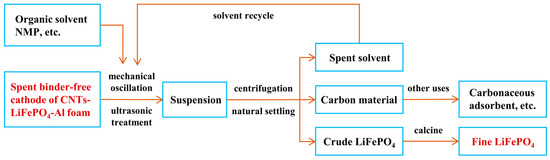
Figure 4.
Recycling process of LFP and CNT nanomaterials from spent binder-free cathode of CNTs-LiFePO4-Al foam. After a green and high-efficiency procedure, lots of fine LFP and CNTs could be recycled from the spent binder-free cathode due to the application of Al foam as current collector and the well-design ratio of LFP and CNTs.
4. Conclusions
We proposed a strategy to fabricate a binder-free cathode using Al foam and CNTs. Owing to the supporting effect and adhesive effect of Al foam and CNTs at macroscopic and microscopic scales, the binder-free cathode of CNTs-LiFePO4-Al foam exhibited good stability with no obvious material detachment before and after the electrochemical tests. Thanks to the enhanced conductivity of the 3D Al conductive network and wrapped CNTs with high electrical conductivity, it also showed excellent performance for high-rate discharge as high as 20 C and long-term life for 9000 cycles. In addition, this electrode structure is also conducive to the recycling of valuable materials in cathodes (LFP and CNTs) through simple ultrasonication, sedimentation, filtration, etc. In considering that the electrode must have sufficient adhesion during the charge–discharge process, yet not too strong to hinder ultrasonic separation, the content of CNTs in the binder-free cathode should be carefully optimized, where 3% CNTs of the mass fraction were optimum in this work.
Supplementary Materials
The following supporting information can be downloaded at https://www.mdpi.com/article/10.3390/batteries10080261/s1: Figure S1: (a,b) Scanning electron microscope (SEM) images of LFP nanoparticles. (c,d) Transmission electron microscope (TEM) images of CNT powders; Figure S2: Optical image of the binder-free cathodes with 3% CNTs: (a) Al foil-based and (b) Al foam-based; Figure S3: SEM image of 5% CNTs cathode, showing that the excessive content of CNTs lead to poor dispersion and severe aggregation; Figure S4: The differential capacity curves (dQ/dV) of the pouch cells with binder-free cathodes: (a) 1% CNTs, (b) 3% CNTs, and (c) 5% CNTs; Figure S5: (a) Optical images of the binder-free cathode with 5% CNTs after ultrasonic treatment for 40 min and 100 min. (b) Optical micrograph of the binder-free cathode with 5% CNTs after ultrasonic treatment for 100 min.
Author Contributions
Conceptualization, C.C. and W.Q.; methodology, Y.J. and Z.Y.; validation, S.W., J.W. and D.L.; investigation, Y.J., J.W. and D.L.; resources, Y.J.; data curation, S.W. and Z.Y.; writing—original draft preparation, Y.J., S.W. and Z.Y.; writing—review and editing, C.C. and W.Q.; visualization, S.W. and Z.Y.; supervision, W.Q; funding acquisition, C.C. and W.Q. All authors have read and agreed to the published version of the manuscript.
Funding
This research was funded by the National Natural Science Foundation of China (No. 22109085 and No. 21975142).
Data Availability Statement
The data that support the findings of this study are available from the corresponding authors upon reasonable request.
Conflicts of Interest
The authors declare no conflicts of interest.
References
- Liu, C.; Li, F.; Ma, L.-P.; Cheng, H.-M. Advanced Materials for Energy Storage. Adv. Mater. 2010, 22, E28–E62. [Google Scholar] [CrossRef] [PubMed]
- Harper, G.; Sommerville, R.; Kendrick, E.; Driscoll, L.; Slater, P.; Stolkin, R.; Walton, A.; Christensen, P.; Heidrich, O.; Lambert, S.; et al. Recycling lithium-ion batteries from electric vehicles. Nature 2019, 575, 75–86. [Google Scholar] [CrossRef] [PubMed]
- Xu, J.; Cai, X.; Cai, S.; Shao, Y.; Hu, C.; Lu, S.; Ding, S. High-Energy Lithium-Ion Batteries: Recent Progress and a Promising Future in Applications. Energy Environ. Mater. 2023, 6, e12450. [Google Scholar] [CrossRef]
- Zhang, M.; Wang, L.; Wang, S.; Ma, T.; Jia, F.; Zhan, C. A Critical Review on the Recycling Strategy of Lithium Iron Phosphate from Electric Vehicles. Small Methods 2023, 7, 2300125. [Google Scholar] [CrossRef] [PubMed]
- Zeng, X.; Li, J. Implications for the carrying capacity of lithium reserve in China. Resour. Conserv. Recycl. 2013, 80, 58–63. [Google Scholar] [CrossRef]
- Wu, J.; Mackenzie, A.; Sharma, N. Recycling lithium-ion batteries: Adding value with multiple lives. Green Chem. 2020, 22, 2244–2254. [Google Scholar] [CrossRef]
- Mancini, M.; Hoffmann, M.F.; Martin, J.; Weirather-Koestner, D.; Axmann, P.; Wohlfahrt-Mehrens, M. A proof-of-concept of direct recycling of anode and cathode active materials: From spent batteries to performance in new Li-ion cells. J. Power Sources 2024, 595, 233997. [Google Scholar] [CrossRef]
- Lv, W.; Wang, Z.; Cao, H.; Sun, Y.; Zhang, Y.; Sun, Z. A Critical Review and Analysis on the Recycling of Spent Lithium-Ion Batteries. Acs Sustain. Chem. Eng. 2018, 6, 1504–1521. [Google Scholar] [CrossRef]
- He, Y.; Yuan, X.; Zhang, G.; Wang, H.; Zhang, T.; Xie, W.; Li, L. A critical review of current technologies for the liberation of electrode materials from foils in the recycling process of spent lithium-ion batteries. Sci. Total Environ. 2021, 766, 142382. [Google Scholar] [CrossRef] [PubMed]
- Du, K.; Ang, E.H.; Wu, X.; Liu, Y. Progresses in Sustainable Recycling Technology of Spent Lithium-Ion Batteries. Energy Environ. Mater. 2022, 5, 1012–1036. [Google Scholar] [CrossRef]
- Su, X.; Fang, H.; Yang, H.; Zou, F.; Li, G.; Wang, L.; Liao, H.; Guan, W.; Hu, X. Cellulose sulfate lithium as a conductive binder for LiFePO4 cathode with long cycle life. Carbohydr. Polym. 2023, 313, 120848. [Google Scholar] [CrossRef] [PubMed]
- Chou, S.-L.; Pan, Y.; Wang, J.-Z.; Liu, H.-K.; Dou, S.-X. Small things make a big difference: Binder effects on the performance of Li and Na batteries. Phys. Chem. Chem. Phys. 2014, 16, 20347–20359. [Google Scholar] [CrossRef] [PubMed]
- Liu, P.; Xiao, L.; Chen, Y.; Tang, Y.; Wu, J.; Chen, H. Recovering valuable metals from LiNixCoyMn1−x−yO2 cathode materials of spent lithium ion batteries via a combination of reduction roasting and stepwise leaching. J. Alloys Compd. 2019, 783, 743–752. [Google Scholar] [CrossRef]
- He, S.; Xiang, W.; He, W.; Yu, F.; Liu, Z. Recovery of spent LiCoO2 cathode material: Thermodynamic analysis and experiments for precipitation and separation of elements. Chem. Eng. J. 2022, 429, 132371. [Google Scholar] [CrossRef]
- Tao, R.; Xing, P.; Li, H.; Sun, Z.; Wu, Y. Recovery of spent LiCoO2 lithium-ion battery via environmentally friendly pyrolysis and hydrometallurgical leaching. Resour. Conserv. Recycl. 2022, 176, 105921. [Google Scholar] [CrossRef]
- Zhou, M.; Li, B.; Li, J.; Xu, Z. Pyrometallurgical Technology in the Recycling of a Spent Lithium Ion Battery: Evolution and the Challenge. Acs EsT Eng. 2021, 1, 1369–1382. [Google Scholar] [CrossRef]
- Landi, B.J.; Ganter, M.J.; Cress, C.D.; DiLeo, R.A.; Raffaelle, R.P. Carbon nanotubes for lithium ion batteries. Energ. Environ. Sci. 2009, 2, 638–654. [Google Scholar] [CrossRef]
- Luo, S.; Wang, K.; Wang, J.; Jiang, K.; Li, Q.; Fan, S. Binder-Free LiCoO2/Carbon Nanotube Cathodes for High-Performance Lithium Ion Batteries. Adv. Mater. 2012, 24, 2294–2298. [Google Scholar] [CrossRef] [PubMed]
- Zhu, X.; Wu, X.; The Nam Long, D.; Tian, Y.; Zhao, H.; Chen, P. Binder-free flexible LiMn2O4/carbon nanotube network as high power cathode for rechargeable hybrid aqueous battery. J. Power Sources 2016, 326, 498–504. [Google Scholar] [CrossRef]
- Guo, Y.; Li, X.; Wang, Z.; Wang, J.; Guo, H.; Yan, G. Free-standing ultrathick LiMn2O4@single-wall carbon nanotubes electrode with high areal capacity. J. Energy Chem. 2022, 73, 452–459. [Google Scholar] [CrossRef]
- Yang, Z.; Tian, J.; Ye, Z.; Jin, Y.; Cui, C.; Xie, Q.; Wang, J.; Zhang, G.; Dong, Z.; Miao, Y.; et al. High energy and high power density supercapacitor with 3D Al foam-based thick graphene electrode: Fabrication and simulation. Energy Storage Mater. 2020, 33, 18–25. [Google Scholar] [CrossRef]
- Yang, Z.; Wang, J.; Cui, C.; Jin, Y.; Zhang, G.; Zhou, H.; Qian, W. High power density & energy density Li-ion battery with aluminum foam enhanced electrode: Fabrication and simulation. J. Power Sources 2022, 524, 230977. [Google Scholar] [CrossRef]
- Wei, S.; Cui, C.; Jin, Y.; Wang, J.; Wang, J.; Li, D.; Qian, W. Enhancement of Li intercalation kinetics of LiFePO4 nanoparticles with mesoporous carbon. Energy Mater. 2024, 4, 400062. [Google Scholar] [CrossRef]
- Qian, W.; Liu, T.; Wang, Z.; Yu, H.; Li, Z.; Wei, F.; Luo, G. Effect of adding nickel to iron-alumina catalysts on the morphology of as-grown carbon nanotubes. Carbon 2003, 41, 2487–2493. [Google Scholar] [CrossRef]
- Qian, W.; Wei, F.; Wang, Z.; Liu, T.; Yu, H.; Luo, G.; Xiang, L.; Deng, X. Production of carbon nanotubes in a packed bed and a fluidized bed. AlChE J. 2003, 49, 619–625. [Google Scholar] [CrossRef]
- Qian, W.; Liu, T.; Wei, F.; Wang, Z.; Luo, G.; Yu, H.; Li, Z. The evaluation of the gross defects of carbon nanotubes in a continuous CVD process. Carbon 2003, 41, 2613–2617. [Google Scholar] [CrossRef]
- Qian, W.; Wei, F.; Liu, T.; Wang, Z. The formation mechanism of the coaxial carbon-metal nanowires in a chemical vapor deposition process. Solid State Commun. 2003, 126, 365–367. [Google Scholar] [CrossRef]
- Delaporte, N.; Ossonon, D.B.; Zaghib, K.; Belanger, D. Fabrication of Current Collectors and Binder-Free Electrodes on Separators Used in Lithium-Ion Batteries. Batter. Supercaps 2020, 3, 638–646. [Google Scholar] [CrossRef]
- Ezzedine, M.; Jardali, F.; Florea, I.; Cojocaru, C.-S. Nanostructured S@VACNTs Cathode with Lithium Sulfate Barrier Layer for Exceptionally Stable Cycling in Lithium-Sulfur Batteries. J. Electrochem. Soc. 2024, 171, 050531. [Google Scholar] [CrossRef]
- Pang, X.; Lee, H.; Rong, J.; Zhu, Q.; Xu, S. Self-Thermal Management in Filtered Selenium-Terminated MXene Films for Flexible Safe Batteries. Small 2024, 20, 2309580. [Google Scholar] [CrossRef] [PubMed]
- Guo, X.; Lan, T.; Feng, X.; Li, D.; Chen, Y. Binder-Free Thin-Film Electrode Fabricated by Spray Drying Method: A Case of LiFePO4. J. Electrochem. Energy Convers. Storage 2021, 18, 011016. [Google Scholar] [CrossRef]
- Wei, T.; Tong, J.; Gao, F.; Weng, J.; Tong, Q. High-rate performance of binder-free LiFePO4 cathode prepared by using various types of conductive carbons. J. Electroanal. Chem. 2022, 927, 116966. [Google Scholar] [CrossRef]
- Ramos-Fajardo, J.M.; Pelaez-Tirado, I.M.; Marin-Rueda, J.R.; Castro-Garcia, M.; Canales-Vazquez, J.; Perez-Flores, J.C. LFP-based binder-free electrodes produced via fused filament fabrication. J. Phys. Energy 2023, 5, 035010. [Google Scholar] [CrossRef]
- Xu, S.; Peng, B.; Pang, X.; Huang, F. Anionic Activity in Fast-Charging Batteries: Recent Advances, Prospects, and Challenges. ACS Mater. Lett. 2022, 4, 2195–2209. [Google Scholar] [CrossRef]
- Li, S.; Wang, K.; Zhang, G.; Li, S.; Xu, Y.; Zhang, X.; Zhang, X.; Zheng, S.; Sun, X.; Ma, Y. Fast Charging Anode Materials for Lithium-Ion Batteries: Current Status and Perspectives. Adv. Funct. Mater. 2022, 32, 2200796. [Google Scholar] [CrossRef]
- Cai, W.; Yao, Y.-X.; Zhu, G.-L.; Yan, C.; Jiang, L.-L.; He, C.; Huang, J.-Q.; Zhang, Q. A review on energy chemistry of fast-charging anodes. Chem. Soc. Rev. 2020, 49, 3806–3833. [Google Scholar] [CrossRef] [PubMed]
Disclaimer/Publisher’s Note: The statements, opinions and data contained in all publications are solely those of the individual author(s) and contributor(s) and not of MDPI and/or the editor(s). MDPI and/or the editor(s) disclaim responsibility for any injury to people or property resulting from any ideas, methods, instructions or products referred to in the content. |
© 2024 by the authors. Licensee MDPI, Basel, Switzerland. This article is an open access article distributed under the terms and conditions of the Creative Commons Attribution (CC BY) license (https://creativecommons.org/licenses/by/4.0/).