Article

Experimental Research on Thermal-Venting Characteristics of the Failure 280 Ah LiFePO4 Battery: Atmospheric Pressure Impacts and Safety Assessment

1
School of Mechanical and Automotive Engineering, Qingdao University of Technology, Qingdao 266520, China
2
Institute of Transportation Studies, University of California Davis, Davis, CA 95616, USA
3
State Key Laboratory of Automotive Safety and Energy, Tsinghua University, Beijing 100084, China
4
Sichuan New Energy Vehicle Innovation Center Co., Ltd., Yibin 644005, China
5
School of Mechanical Engineering, Dalian Jiaotong University, Dalian 116028, China
*
Authors to whom correspondence should be addressed.
Batteries 2024, 10(8), 270; https://doi.org/10.3390/batteries10080270
Submission received: 1 July 2024 / Revised: 20 July 2024 / Accepted: 24 July 2024 / Published: 29 July 2024
(This article belongs to the Special Issue Thermal Safety of Lithium Ion Batteries)

Abstract

:
With the widespread application of lithium-ion batteries (LIBs) energy storage stations in high-altitude areas, the impact of ambient pressure on battery thermal runaway (TR) behavior and venting flow characteristics have aroused wide research attention. This paper conducts a lateral heating experiment on 280 Ah lithium iron phosphate batteries (LFPs) and proposes a method for testing battery internal pressure using an embedded pressure sensor. This paper analyzes the battery characteristic temperature, internal pressure, chamber pressure, and gas components under different chamber pressures. The experiment is carried out in a N2 atmosphere using a 1000 L insulated chamber. At 40 kPa, the battery experiences two instances of venting, with a corresponding peak in temperature on the battery’s side of 136.3 °C and 302.8 °C, and gas generation rates of 0.14 mol/s and 0.09 mol/s, respectively. The research results indicate that changes in chamber pressure significantly affect the center temperature of the battery side (Ts), the center temperature of the chamber (Tc), the opening time of the safety valve (topen), the triggering time of TR (tTR), the time difference (Δt), venting velocity, gas composition, and flammable limits. However, the internal pressure and gas content of the battery are apparently unaffected. Considering the TR characteristics mentioned above, a safety assessment method is proposed to evaluate the TR behavior and gas hazard of the battery. The results indicate that the risk at 40 kPa is much higher than the other three chamber pressures. This study provides theoretical references for the safe use and early warning of energy storage LIBs in high-altitude areas.

1. Introduction

Lithium iron phosphate batteries (LFPs) have lots of advantages, such as a high voltage, small size, high energy density, no memory effect, and a long lifespan [1]. They are widely used in electrochemical energy storage and other fields [2]. However, security is the bottleneck restricting the large-scale application of high-specific-energy LFPs [3].
The reliability and quality of a power supply cannot be guaranteed effectively because of the shortage of conventional energy and the difficulty of supplying the plateau area. But renewable energy sources such as hydro, solar, and wind power are widely distributed. However, renewable energy is intermittent and unstable, and electrochemical energy storage power stations are the main solution. More and more energy storage stations are landing at high altitudes [4]. In the high-altitude energy storage field, accidents caused by LFPs thermal runaway (TR) are increasing, as reported in previous studies [5]. Therefore, studying the TR characteristics and mechanisms of large-capacity LFPs at low pressure, especially for high-altitude areas, is of great importance [6].
When the internal heat generation rate of lithium-ion batteries (LIBs) is higher than the heat dissipation rate, the internal chemical reaction will be aggravated [7], which causes the battery to burn and explode. In recent years, many researchers have explored the causes and characteristics of battery TR. Feng et al. [8] found mechanical abuse, thermal abuse and electrical abuse were the main causes of TR of LIBs. Tran et al. [9] discussed the reasons for the large-scale internal short circuit caused by TR, focusing on the collapse of the diaphragm, and summarized the existing methods for establishing TR models. Li et al. [10] studied the mechanism of thermal runaway after rapid charging of batteries. The results showed that the reaction between lithium plating and electrolyte was the trigger for thermal runaway. Guo et al. [11] studied the impact of the heat-transfer coefficient on the TR response. They found that an increase in the heat transfer coefficient led to a shorter heat absorption phase in the battery, resulting in a shorter triggering time for TR, and the critical temperature for triggering TR in the battery also increased. The maximum battery temperature remained 430 K when the heat-transfer coefficient was higher than 25 W/(m2∙K). Xu et al. [12] studied the impact of charge and discharge rates on the TR of LIBs. The results indicated that the higher the charge rate, the higher the peak temperature of TR. When the charging rate was 1C, the peak temperature was 362.15 °C and the time was 283 s. When the charging rate was 3C, the peak temperature was 364.62 °C and the time was 284 s. Paster et al. [13] studied the differences in TR between aged and normal LIBs. The results indicated that the heat released during TR in aged batteries is significantly lower than in normal ones, due to the reduction in lithium in the anode and electrolyte. Li et al. [14] have created a model of an aluminum heat sink to study the impact of different structural arrangements on the TR of LIBs. When there is no thermal management structure, the average temperature of the battery is greater than 500 °C, and when there is a thermal management structure, the temperature of the four adjacent batteries is lower than 120 °C.
TR of LIBs produces flammable gases [15], and it is important to study the gas content and flammability for TR protection. Chen et al. [16] studied the TR gas composition and used the Le Chatelier Formula to calculate the lower flammability limit (LEL). They found that with the increase in the state of charge (SOC), the LEL showed a trend of initially rising and then declining. When the battery SOC was 60%, the LEL was the largest at 21.10%. When the battery SOC was 100%, the LEL was the smallest at 5.08%. Zhang et al. [17] used gas chromatography (GC) analysis of produced gas components, and they found that an increase in the multi-chain gas component proportion in mixed gas was the cause of the increase in the combustible limit range. Baird et al. [18] compared the flammability limits of Lithium Nickel Manganese Cobalt Oxide (NMC), LFP, Lithium Cobalt Oxide (LCO), and Nickel Cobalt Aluminum (NCA), and found that among the four types of batteries, LCO has the lowest LEL at 6.1%, while NCA has the highest LEL at 11.8%.
The venting gases of the LIBs safety valve after opening also enhances the thermal radiation [19] and the impact on the battery TR behavior, and the resulting harm to the environment cannot be ignored [20]. Zhou et al. [21] used a high-speed camera to study the gas venting behavior of LIBs during TR, and LIBs exhibited two distinct venting streams with speeds of 55 m/s and 40 m/s, respectively. Kang et al. [22] studied the thermal characteristics that led to thermal runaway of LPF batteries of different capacities under overcharge conditions. The experimental results showed that the danger caused by TR increases with the increase in capacity, and the maximum temperature of a 140 Ah battery is 476 °C, and the maximum temperature of an 86 Ah battery is 374 °C.
With the extensive application of LIBs in plateau energy storage, research on the TR characteristics and mechanism of batteries under low pressures is a hotspot at present [23]. Liu et al. [24] studied the effect of low-pressure environments on the TR of LIBs. Their research found that the propagation velocity of TR increased with the chamber pressure. When the chamber pressure increased from 0 atm to 1 atm, the propagation velocity increased by 170%. Li et al. [25] studied the effects of low pressure on gas content components. They found that as the pressure decreased, the content of CO increased, while the content of CO2 decreased. It was caused by incomplete flammability under low pressure. Liu et al. [26] studied the temperature changes of LIBs under different chamber pressures and found that the peak TR temperature is lower at low pressure. Ding et al. [27] studied several key parameters, including the opening time of the safety valve (topen), the triggering time of TR (tTR), and the time difference (Δt). The results showed that as the chamber pressure decreased from 101 kPa to 30 kPa, tTR exhibited an increasing trend. When the chamber pressure decreased from 101 kPa to 30 kPa, Δt decreased to 22 s. Sun et al. [28] used LiNi0.5Co0.2Mn0.3O2 soft-pack batteries with a capacity of 10,000 mAh to perform TR experiments in the air at different low pressures. The researchers found that as the pressure in the test chamber increased, a significant flame appeared and the temperature of the battery increased. Zhao et al. [29] introduced a hierarchical framework that takes advantage of emerging trends in practical, cloud-based artificial intelligence technologies. The core of this approach is comprehensive monitoring, early diagnosis, and risk prediction at the battery, package, and system level to improve battery safety.
There have been many studies on the thermal runaway characteristics of LFPs at low pressure, mainly from several perspectives such as gas production and temperature change [30]. The innovation of this paper is that the battery is modified and the pressure sensor is embedded to detect the battery pressure change. In order to further explore the influence of different chamber pressures on the thermal runaway of the battery in inert gases, the relative most dangerous chamber pressure is determined to provide a reference for the safe use of high-altitude or aviation LFPs. Therefore, this study conducts lateral heating experiments on a 280 Ah LIBs and proposes a method for testing internal pressure using an embedded pressure sensor. The study analyzes the battery’s characteristic temperature, internal pressure and chamber pressure, gas content characteristics, gas mixture composition, and flammable limits under chamber pressures of 40 kPa, 60 kPa, 80 kPa, and 101 kPa. This research explains the mechanism of the influence of chamber pressure on battery TR. It combines with characteristic parameters, quantitatively predicts its risk, aiming to provide theoretical reference for the safe use of LFPs in high-altitude energy storage and aviation fields.

2. Thermal Runaway Experimental Equipment and Methods

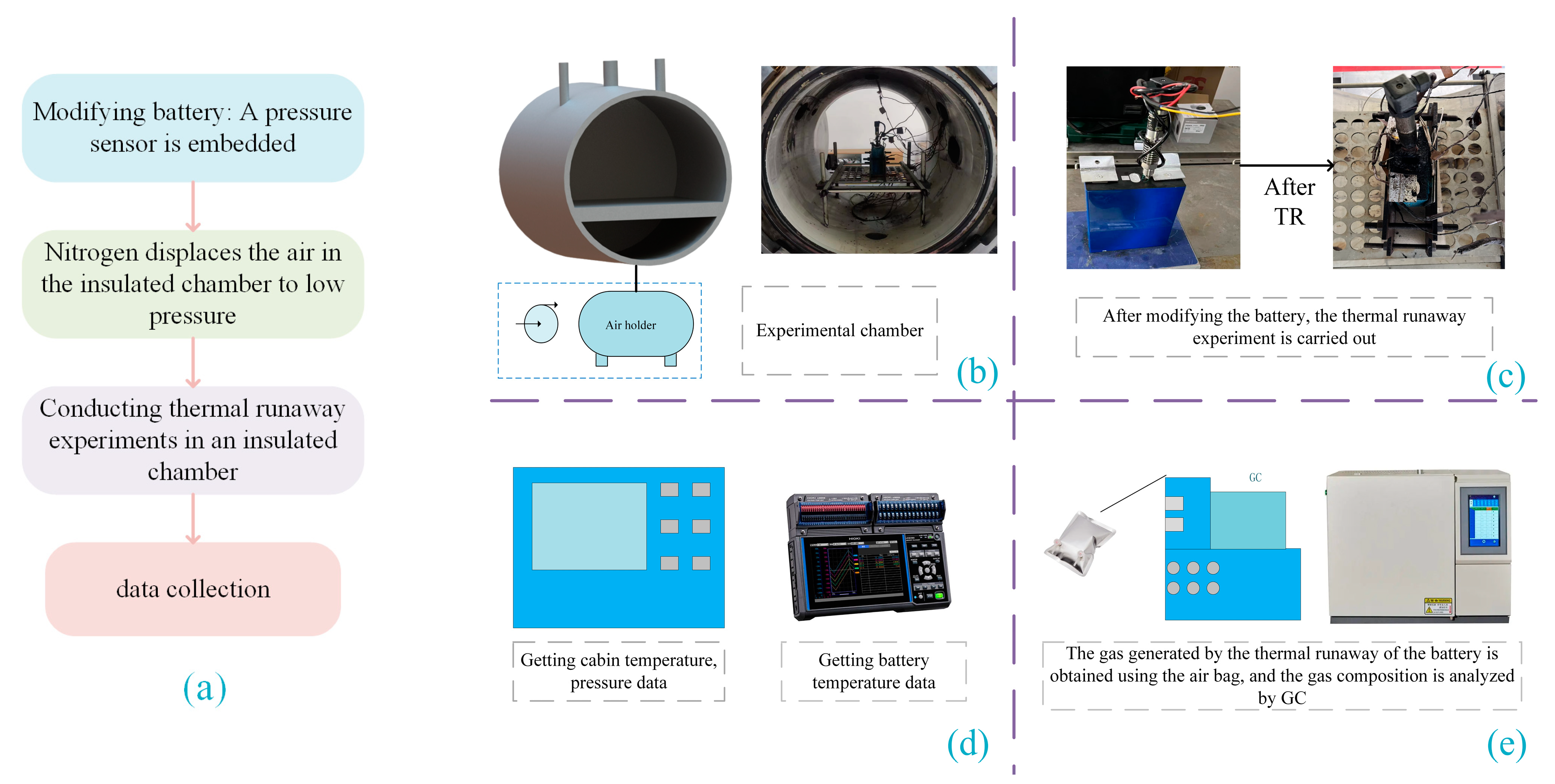
2.1. Methodology and Procedure

As shown in Figure 1a, the overall experiment has four parts. Firstly, the battery is modified with an embedded pressure sensor. Nitrogen is then used to replace the air in the sealed chamber to reach different pressure. Finally, the thermal runaway experiment is conducted to obtain the experimental data. As shown in Figure 1b, the experimental chamber is cylindrical. The internal volume of the chamber is 1000 L, the highest operating temperature is 1500 K, and the maximum pressure is 5 MPa. The rear gas pump is connected to charge nitrogen. After the replacement, the chamber is left to stand for 2 h to observe whether the air tightness is good. Figure 1c shows the battery comparison before and after the experiment, and the fixture uses 2 N·m clamping force to fix the battery. As shown in Figure 1d, the data in the chamber are collected by a specific device, and the data of the battery are obtained by the data collector model HIOKI LR8431-30. As shown in Figure 1d, the model is a TRACE 1300 gas chromatograph (GC). The gas bag is used to collect the gas generated by the thermal runaway of the battery, and then the gas is sent into the GC to analyze the gas composition. This process is repeated three times. It is worth noting that many researchers use the accelerated rate calorimeter (ARC) for TR experiments, but this paper is not tested with ARC. The reason is that ARC has a pressure reduction process, the lumen pressure is difficult to change, and ARC cannot meet the needs of replacing the inert gas. Therefore, this paper is conducted in the equipment developed by itself. Qian et al. [15] also used the same equipment to study TR gas generation behavior. The data acquisition system includes sensors for temperature and pressure measurements within the chamber.

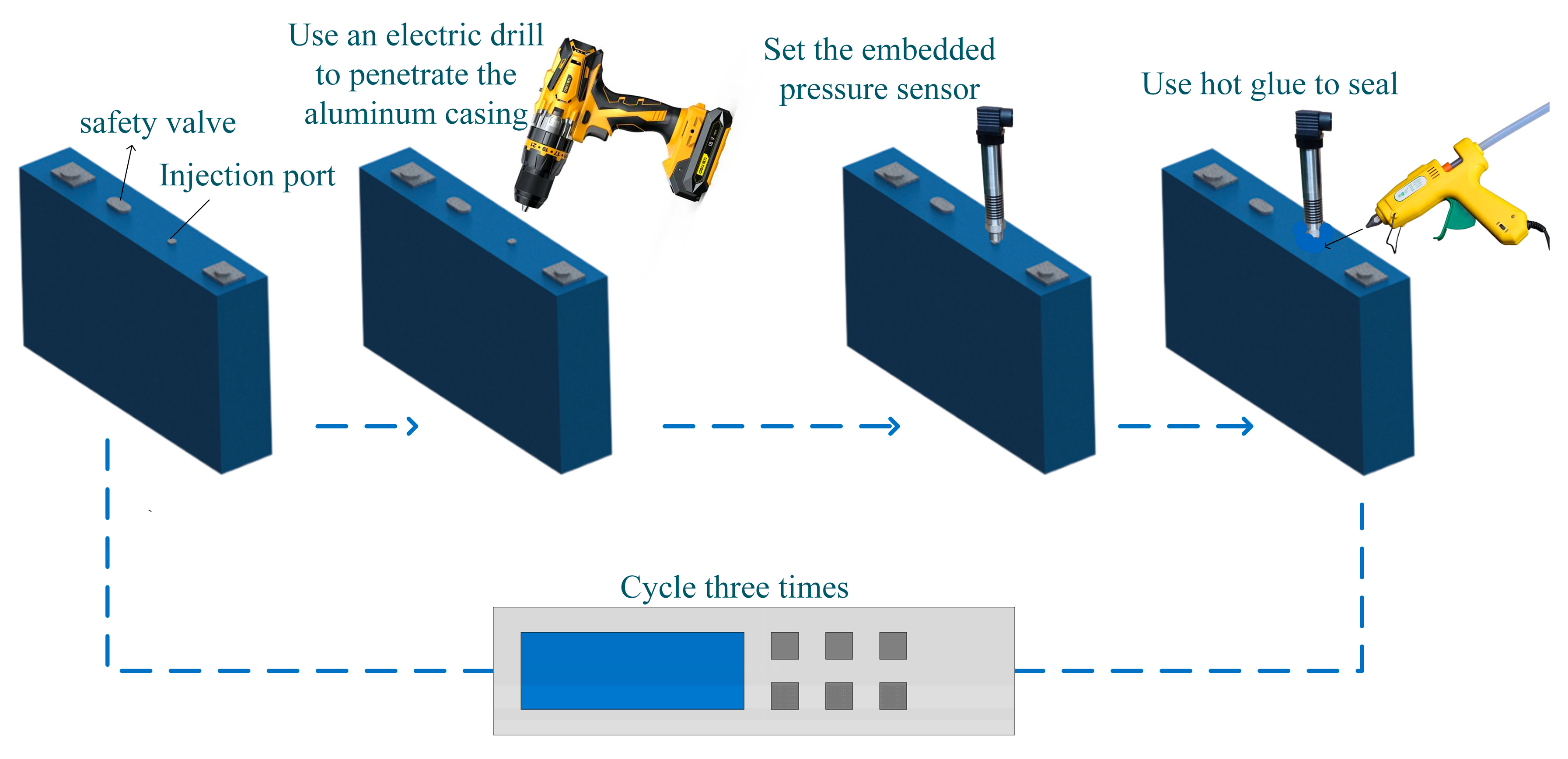
2.2. Battery with Embedded Sensor

The experimental sample utilizes capacity-type LFPs with a rated capacity of 280 Ah. The battery shell dimensions are 207 × 72 × 174 mm, with an internal volume of 0.25 L. The battery cover is equipped with a safety valve measuring 12 mm in length and 20mm in diameter. The electrolyte of the battery is LiPF6, and the solvent for the electrolyte comprises ethylene carbonate (EC), methyl ethyl carbonate (EMC), and dimethyl carbonate (DMC) in a ratio of 1.9:2.8:1. Their respective evaporation temperatures are measured at 248 °C, 107 °C, and 90.1 °C, with a saturated vapor pressure of 5.54 kPa and an evaporation temperature of 151.1 °C.The battery used in this paper is provided by Xiamen Haichen New Energy Technology Co. Ltd.,Xiamen, China, as detailed in Table 1, which showcases comprehensive battery parameters.
Zhang et al. [31] used the embedded sensor to obtain the internal thermal state of the battery. This paper also uses the same method. The embedded pressure sensor schematic is shown in Figure 2. Firstly, the battery is discharged to 0% SOC, and then the hole is drilled by a hand drill in the glove box. The pressure sensor is installed using hot melt adhesive. The modified battery is tested for charging and discharging to determine its capacity state. The capacity of the battery is recorded for three charge–discharge cycles. The difference between the three results and the battery capacity before the reform is within 5%, which proves that the modification method is feasible.

2.3. Thermal Runaway Experiment

In order to measure the temperature and pressure, pressure sensors and thermocouples are installed. To ensure the accuracy of the data, the thermocouples are firmly secured to the battery’s surface using insulation tape. The sensor placement is shown in Figure 3. Thermocouple (T3) and pressure sensor (P2) are arranged in the center of the chamber. Thermocouples (T1) and (T2) are positioned in the center of the battery’s side and on the safety valve. The embedded sensor (P1) is placed 2–3 cm below the battery’s upper housing. The thermocouples are ETA GG-K-30; the pressure sensors are HM90.
In this experiment, a front heating method was used to trigger TR of the battery. As shown in Figure 3, the heating plate is fixed to the large side of the battery using a fixture. The power of the heater is 2000 W. The heating plate and the battery are in close contact and are fixed in the chamber with a fixed splint. Then, the gas replacement of the chamber is carried out. Firstly, the vacuum pump is used to replace nitrogen to reach 40 kPa, 60 kPa, 80 kPa, and 101 kPa, respectively, to simulate the plateau environment. After holding for 1 h, the battery TR experiment can be started. The experimental data are automatically collected by the data acquisition system. The gas mixture in the chamber is collected by the airbag for GC analysis.

3. Thermal-Venting Characteristics at 40 kPa

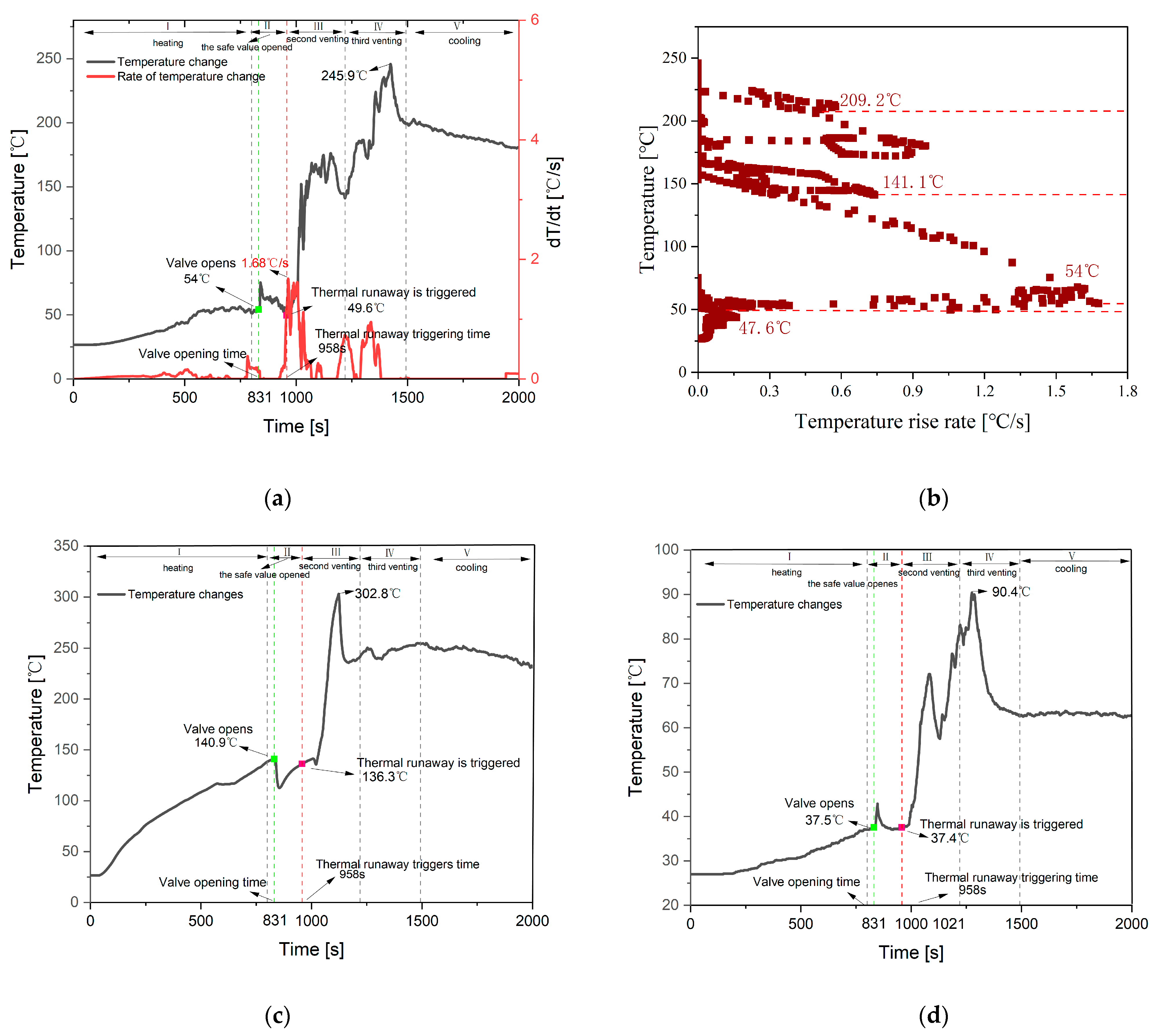
3.1. Feature Temperature

At 40 kPa, the temperature characteristics of the safety valve (Tv), center temperature of battery side (Ts), and the center temperature of chamber (Tc) are obtained, as shown in Figure 4. Figure 4a–d show the temperature change curves of the Tv and the temperature rise rate of valves Ts and Tc, respectively.
As shown in Figure 4a,b, at 40 kPa, the Tv shows three rapid increases. The Tc also shows a similar pattern of shift, while the Ts shows two rapid rises. Based on the temperature change pattern of the valve, the TR of the battery is divided into five stages as shown in Table 2, with the time range and typical characteristics of each stage listed in Table 2.
From Table 2, it can be seen that in Stage I, the battery is in the heating stage, and the battery temperature is rising. The main chemical reaction that occurs in this stage is the decomposition of the SEI film [32], as shown in reaction Equations (1) and (2).
(CH2OCO2Li)2 → Li2CO3 + C2H4 + CO2 + 1/2O2
2Li + C3H4O3 → Li2CO3 + C2H4
Stage II: The battery safety valve opens at 831 s and the Ts is 140.9 °C. After the safety valve opens, a large amount of chemical reaction mixture and electrolyte vapor is ejected from the safety valve, carrying a large amount of heat into the chamber. Both of which reach their first peak in this stage. The Ts decreases rapidly due to heat exchange. The main chemical reaction that occurs in this stage is that the lithium metal embedded in the negative electrode reacts with the electrolyte [33], as shown in reaction Equations (3)–(5).
2Li + C3H4C3 (EC) → Li2CO3+C2H4
2Li + C5H10O3 (DEC) → LiCO3+C2H4+C2H6
2Li + C3H6O3 (DMC) → LiCO3+C2H6
Stage III: The range of Tv is between 49.8 °C and 176.2 °C. The temperature change rate reaches 1 °C/s at 958 s, defining the moment of TR triggering, which corresponds to a Tv of 49.6 °C. Tv reaches its peak change rate at 964 s, which is 1.68 °C/s. At this moment, a large amount of heat is transferred to the chamber, causing a rapid increase in temperature. Tc reaches a second peak at 1084 s, corresponding to a temperature of 71.6 °C. Subsequently, the temperature decreases to 57.8 °C after 1084 s. Ts reaches its peak at 1123 s, which is 302.8 °C. At this stage, the main decomposition process of the battery is film melting, and the direct contact of the positive and negative electrodes causes an internal short circuit, releasing a large amount of heat and emitting gases such as O2, C2H4, HF, and PF5, as shown in Equations (6)–(8).
LiPF6 → LiF + PF5
PF5 + H2O → POF3 + 2HF
C3H6O3 (DMC) + PF5 → CH3OCOOPF4 + CH3F
Stage IV: As the chemical reaction progresses, Tc reaches its third peak at 1275 s, at 90.4 °C, and then rapidly decreases. Tv continues to rise rapidly during this stage, reaching its third peak at 245.9 °C at 1424 s. As the reaction progresses and the internal active material decreases, the chemical reaction rate gradually weakens, and the temperature begins to decrease. Ts fluctuates around 245 °C, with little increase in temperature. The chemical reaction occurring in this stage involves the decomposition of the positive electrode material to produce O2 and react with the solvent to generate CO and CO2, as shown in Equations (9)–(11).
Li1 − xFePO4 → (1 − x) LiFePO4 + x/2 Fe2P2O7 + x/4O2
5/2O2 + C3H4O3 (EC) → 3CO2 + 2H2O
O2 + C3H4O3 (EC) → 3CO + 2H2O
Stage V: Chemical reactions weaken, and the battery enters the cooling stage.

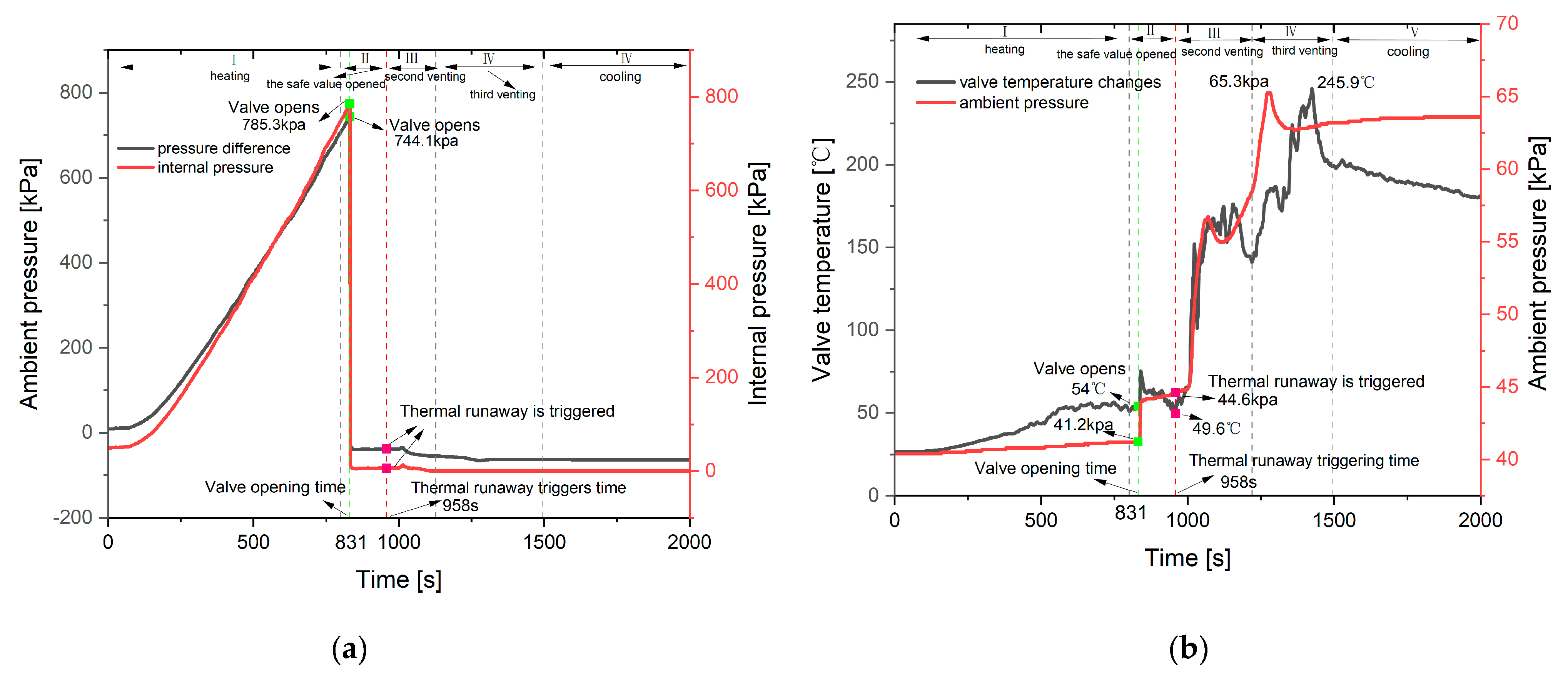
3.2. Internal and Chamber Pressure

The internal pressure changes of the battery, the pressure inside the chamber, and the temperature and pressure difference changes of the safety valve at 40 kPa are shown in Figure 5.
From Figure 5a, it can be seen that the internal pressure of the battery exhibits a rapid increase, followed by a rapid decrease, and then stabilizes. From Figure 5b, it can be observed that the trend of pressure change in the chamber shows three rapid increases, similar to the three peak-like increases in the Tv.
Stage I: The internal pressure range of the battery is 49.4–747.7 kPa. From 0 s to 66 s, the internal pressure remains basically unchanged, and the Tv fluctuates around 26.5 °C. During this time range, the temperature is far below the decomposition temperature of the SEI membrane and the evaporation temperature of the electrolyte, indicating that the electrolyte is in a relatively stable state. From 66 s to 831 s, the internal pressure of the battery increases linearly, and this curve can be fitted into a pressure/time function expression as shown in Equation (12). Correspondingly, the range of Ts is 31.2–140.9 °C, and the SEI membrane begins to undergo a decomposition reaction.
y = −78.97 + 1.005x
Stage II: At 831 s, the critical pressure inside the battery before the safety valve opens is 747.7 kPa. After the valve opens, the interior of the battery is connected to the chamber, and the pressure inside the chamber is 44.1 kPa. Subsequently, the pressure slowly increases.
Stage III: At 958 s, TR is triggered, leading to a violent internal chemical reaction. The electrolyte boils, the separator melts, and the positive and negative electrodes come into contact. As the temperature rises, the internal energy of the gas increases, causing the pressure inside the chamber to rapidly rise during this stage. At 1068 s, the pressure inside the chamber reaches 56.7 kPa.
Stage IV: The pressure inside the chamber continues to rise. At 1277 s, it reaches the peak of the entire TR process, at 65.3 kPa.
Stage V: The internal chemical reactions of the battery gradually weaken, leading to a slower gas content rate. The pressure inside the chamber slowly increases. Eventually, due to the accumulated gas not being released, the pressure inside the chamber stabilizes at 63.6 kPa.

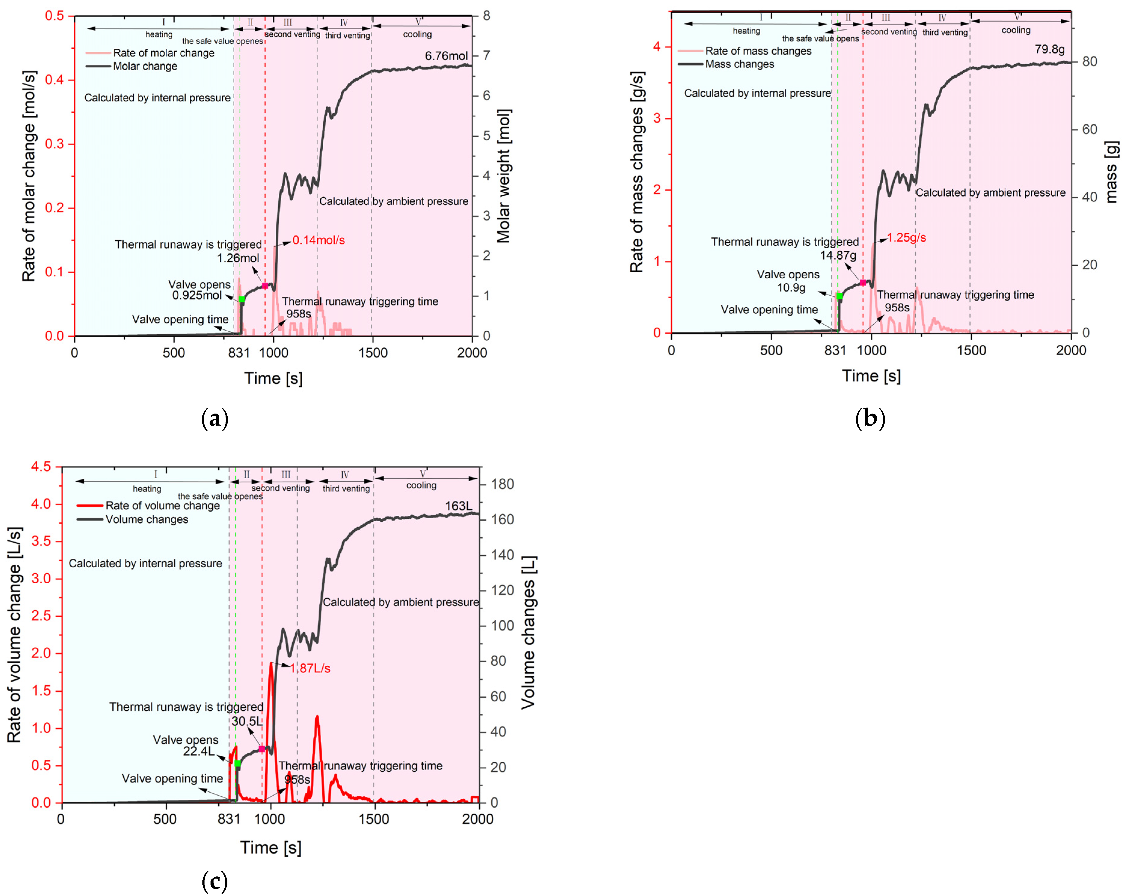
3.3. Venting Flow Characteristics

3.3.1. Component Identification

Using GC for gas component analysis, the gas composition of the 40 kPa is shown in Figure 6. From Figure 6, it can be seen that the main components of the gas produced by the battery under low pressure are H2, CO2, and CH4, accounting for 46%, 26%, and 12%, respectively. Among them, hydrogen has the highest proportion.

3.3.2. Flammability Analysis

In order to evaluate the safety of gas generation during TR of batteries, because the mixture gas contains incombustible CO2, the improved Le Chatelier formula is used to calculate the flammability limits of the gas mixture. The lowest and highest concentrations at which a flammable gas mixture can ignite with air are referred to as LEL and UEL, respectively [34]. The flammability limit range is obtained by subtracting the LEL from the UEL, as shown in Equations (13)–(17).
L m   =   100 V 1 L m 1 + V 2 L m 2 + V 3 L m 3 + V 4 L m 4
L E L = L m ( 1 + D 100 D ) × 100 100 + L m ( D 100 D ) × 100 %
U m   =   100 V 1 L u 1 + V 2 L u 2 + V 3 L u 3 + V 4 L u 4
U E L = U m ( 1 + D 100 D ) × 100 100 + U m ( D 100 D ) × 100 %
Range = U E L     L E L
In the formula, Lm is the lower limit of flammability without inert gases, Vnumber represents the volume proportion of different gases,  L   n u m b e r  represents the lower flammability limit for different gases, and  D  is the volume proportion of inert gases. Um is the upper flammability limit excluding inert gases;  U n u m b e r  represents the upper flammability limit of different gases.
The text describes the flammability limits of various components in a mixed gas. It mentions the LEL as a percentage of the volume fraction of each component in the mixed gas, and the UEL as a percentage of the volume fraction of each component. It also introduces R as representing the flammability limit range.
The explosion upper and lower limits of each component gas are shown in Table 3. By substituting the LEL of each gas into Equation (14), LEL of the mixed gas can be obtained. By substituting into Equation (16), the UEL can be obtained. The calculation yields a LEL of 6.42% for the mixed gas and a UEL of 63%. The range is 56.6%.

3.3.3. Gas Content Calculation

In this experiment, it is assumed that the generated gas conforms to the ideal gas assumption. The mass flow rate, volume flow rate, and mass change characteristics of the gas produced by the battery can be calculated based on the differential form of the ideal gas state equation. Before the safety valve opens, the change in gas content inside the battery can be calculated based on the internal gas pressure characteristics of the battery, as in Equation (18). After the safety valve opens, the change in gas from the battery venting can be calculated based on the pressure inside the chamber, as in Equation (19).
d n 1 d t   =   d P a d t V 1 R d T a d t
d n 2 d t = d P b d t V 2 R d T b d t
The total gas content is obtained by integrating the rate of change of gas content after the valve is opened. During the time period t1, the gas produced internally is of equal mass.
n = t 1 t 2 d n 2 d t d t
In the equation, n1 is the gas content before valve opening, n2 is the gas content after valve opening, Ta is the temperature before valve opening, Tb is the temperature after valve opening, Pa is the internal gas pressure of the battery, Pb is the gas pressure inside the flammability chamber, V1 is the internal volume of the battery, V2 is the volume of the chamber, and R is the gas constant, which is 8.314 J/mol·K [35].
After calculating the gas generation, the quality can be calculated using the following Formulas (21)–(24).
d m 1 d t   =   d n 1 d t M 0
d m 2 d t   =   d n 2 d t M 0
m = t 1 t 2 d m 2 d t d t
M 0   =   p 1 M 1 + p 2 M 2 + p n M n
In the equation: m1 is the mass before the valve is opened, m2 is the mass after the valve is opened, M0 is the molar mass equivalent, and the calculated value of M0 is 10.6 g/mol. p% represents the percentage composition of each gas and Mnumber represents the molar mass of a specific gas.
The volume can be calculated using the following formula.
V = t 1 t 2 d V 2 d t d t ρ 0
ρ 0   =   p 1 ρ 1   +   p 2 ρ 2   +     p n ρ n
In the equation, the equivalent density can be calculated as 0.439 g/m3, where p% represents the proportion of each gas (as shown in Figure 6), and is the density of a certain gas.

3.3.4. Venting Flow Characteristics

According to theoretical calculations, the cumulative gas content, cumulative mass, and cumulative volume of the battery over time at 40 kPa are shown in Figure 7. The blue area in the figure represents the gas content calculated using the internal pressure, while the red area represents the gas content calculated using the internal pressure of the chamber after the safety valve is opened.
From Figure 7, it can be seen that the gas content and the mass volume both show a trend of rapid increase and fluctuation. The reaction rate has three peaks corresponding to the three stages of TR.
Stage I: The battery is in the heating stage, maintaining a relatively stable state. At this time, the safety valve is not open and the gas content is minimal. At 800 s, the accumulated gas content is 0.067 mol, the accumulated mass is 0.79 g, and the accumulated volume is 1.62 L.
Stage II: At 831 s, the safety valve opens, and high-temperature and high-pressure gas inside the battery is ejected into the chamber. The rate of change of gas content reaches the first peak, with a rate of 0.09 mol/s, and the cumulative gas content is 0.93 mol. The cumulative gas volume and cumulative gas mass change trends are the same as the gas content, at 10.9 g and 22.4 L, respectively.
Stage III: At 958 s, the battery experienced TR, triggering a vigorous internal chemical reaction and a rapid increase in gas content. At 1008 s, the rate of change in gas content reached a second peak of 1.87 L/s. At this point, the cumulative gas content was 4.07 moles, with a cumulative gas mass of 48.06 g and a cumulative gas volume of 98.5 L. Subsequently, the cumulative gas content fluctuated around 4 moles due to convective heat exchange between gases at different temperatures inside the chamber, causing fluctuations in temperature and pressure, which in turn affected the cumulative gas content. As the convective heat exchange between hot and cold air inside the chamber ceased, the noticeable fluctuations disappeared, and the gas content continued to increase.
Stage IV: As the TR reaction of the battery continues, the rate of change in cumulative gas content reaches a third peak at 1224 s. At this time, the cumulative gas content is 6.61 mol, with a mass of 78.17 g and a volume of 160 L.
Stage V: The battery enters the cooling stage, and the chemical reaction basically stops. The gas content behavior of the battery stops at 1493 s. The final cumulative gas content is 6.76 mol, with a cumulative gas mass of 79.8 g and a cumulative gas volume of 163 L.

4. Pressure Effect on Thermal Behavior

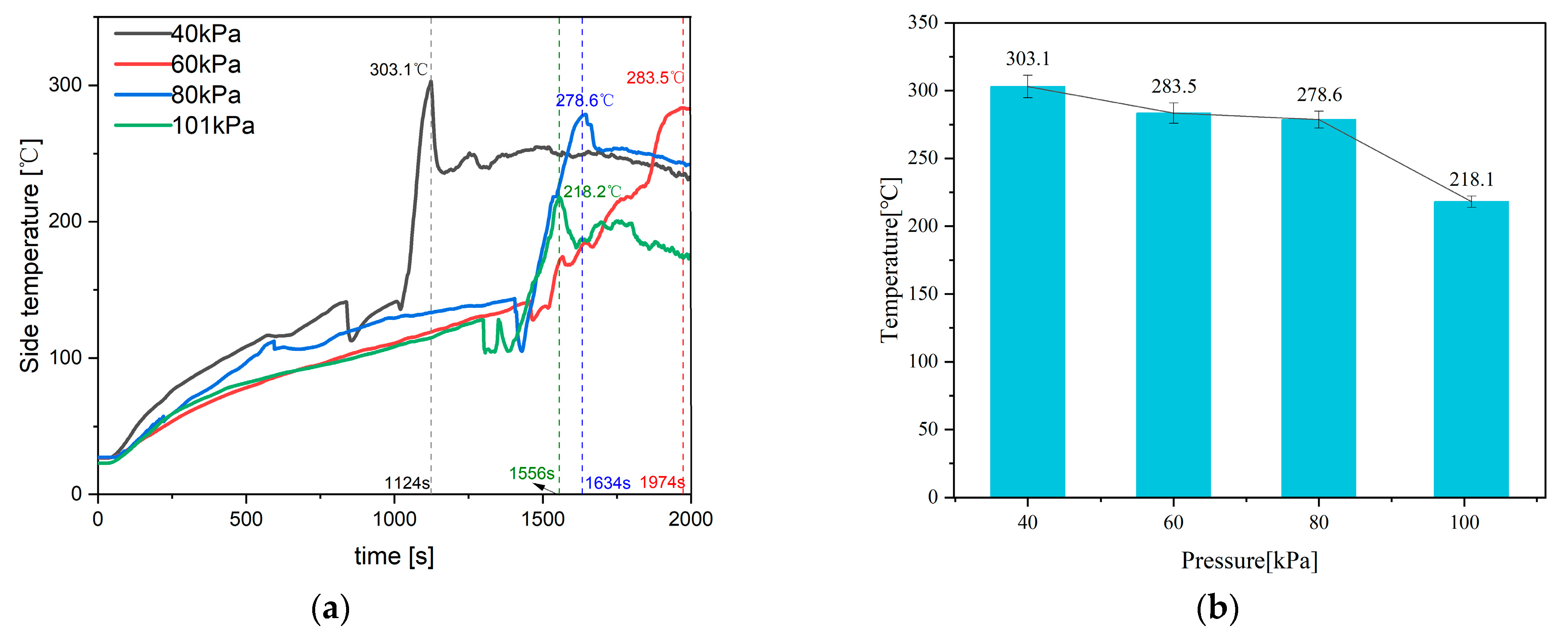
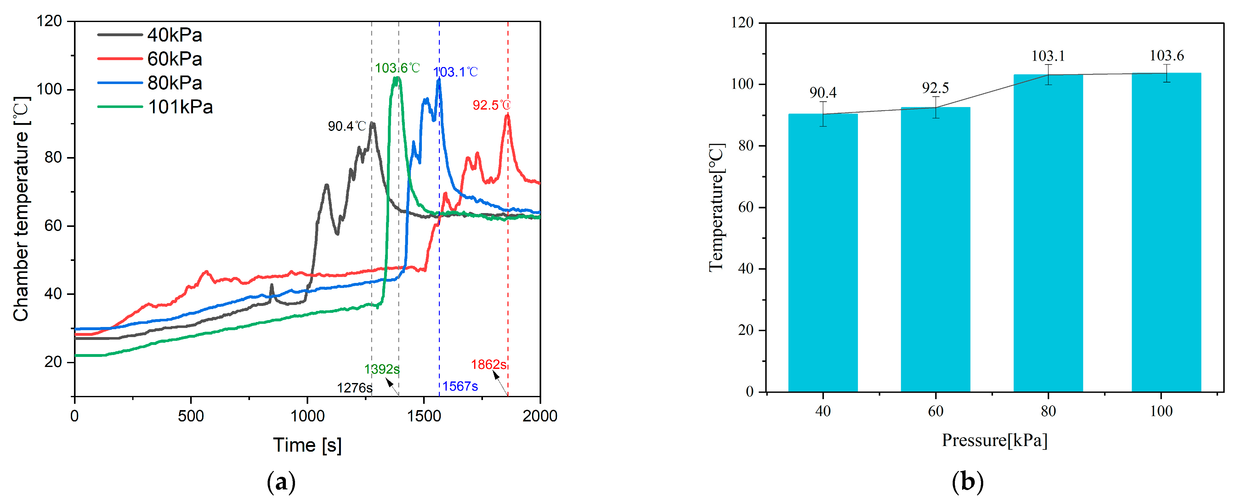
4.1. Feature Temperature

The paper explores the influence mechanism of different chamber pressures on the failure characteristics of battery. The inert gas pressure inside the chamber is controlled at 40 kPa, 60 kPa, 80 kPa, and 101 kPa, respectively. The Ts and the peak temperature under different pressure environments are shown in Figure 8.
As shown in Figure 8a, at 40 kPa, the peak temperature of Ts reached 303.1 °C at 1124 s. At 101 kPa, the peak of Ts reached 218.1 °C at 1556 s. At 80 kPa, the peak of Ts reached 278.6 °C at 1634 s. At 60 kPa, the peak of Ts reached 283.5 °C at 1974 s. The time to reach peak temperature is in the order of 40 kPa < 101 kPa < 80 kPa < 60 kPa, and the peak temperature is in the order of 40 kPa > 60 kPa > 80 kPa > 101 kPa. The peak temperatures for the four pressures are shown in Figure 8b, and the peak temperature decreases with increasing chamber pressure.
At 40 kPa, Ts reaches its peak faster compared to the other three pressures. TR is triggered earliest at 40 kPa, leading to a quicker generation of a large amount of heat. Ts increases as the pressure decreases because of the increase in pressure inside the chamber, where more inert gas is erupting into the chamber, effectively diluting the concentration of reaction gas, suppressing TR, and correspondingly exhibiting the suppression of Ts rise.
The Tc under four different pressures is shown in Figure 9. At 40 kPa, Tc first reaches its peak at 1276 s, reaching 90.4 °C. At 101 kPa, Tc first reaches its peak at 1392 s, reaching 103.6 °C. At 80 kPa, Tc first reaches its peak at 1567 s, reaching 103.1 °C. At the 60 kPa, Tc first reaches its peak at 1862 s, reaching 92.5 °C. The order of peak temperature attainment time is 40 kPa < 101 kPa < 80 kPa < 60 kPa, and the order of peak temperature from low to high is 40 kPa < 60 kPa < 80 kPa < 101 kPa. The peak temperatures at four pressures are shown in Figure 9b. As the pressure increases, the maximum Tc continues to increase.
The temperature trends under four different pressures are the same, and the peak of Tc increases at higher pressure. However, the Ts changes shown in Figure 8 decrease with increasing pressure. The reason for this difference is that with higher pressure, the gas heat transfer coefficient is higher, making it easier for the temperature inside the chamber to rise.

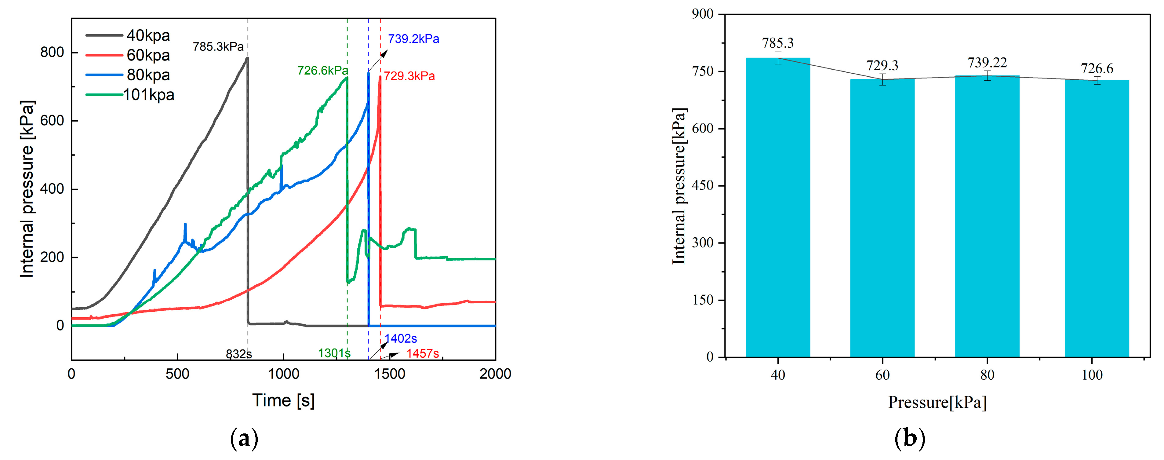
4.2. Internal and Chamber Pressure

This study replaces the air with nitrogen and maintains 40 kPa, 60 kPa, 80 kPa, and 101 kPa to conduct TR experiments. The curves of the internal pressure change of the battery are shown in Figure 10.
As shown in Figure 10a, the curve represents the internal pressure changes in the battery. Due to the opening of the safety valve, the trend is an initial increase followed by a decrease. At 40 kPa, the safety valve opens at 831 s, corresponding to a peak pressure of 725.3 kPa. At 101 kPa, the safety valve opens at 1301 s, with a peak pressure of 726.6 kPa. At 80 kPa, the safety valve opens at 1402 s, with a peak pressure of 739.2 kPa. At 60 kPa, the safety valve opens at 1457 s, with a peak pressure of 729.3 kPa. The peak pressures are ranked from high to low as 80 kPa > 60 kPa > 101 kPa > 40 kPa. It is worth noting that at 40 kPa, the internal pressure of the battery increases the fastest.
As shown in Figure 10b, the peak internal pressure of the battery under four different chamber pressures is similar. The difference is only 0.8%.
The pressure change curve inside the chamber is shown in Figure 11a. At the moment when the battery safety valve is opened, a large amount of gas enters the chamber, causing a rapid increase in pressure inside the chamber. At 40 kPa, the peak pressure is 65.3 kPa, at 60 kPa, the peak pressure is 88 kPa. At 80 kPa, the peak pressure is 116.9 kPa, and at 101 kPa, the peak pressure is 147.4 kPa. The peak pressures are sorted in ascending order as 40 kPa < 60 kPa < 80 kPa < 101 kPa.
As shown in Figure 11b, the internal pressure and the pressure increment inside the chamber increase linearly with the increase in chamber pressure. The main reason for this is that the temperature inside the chamber increases with the increase in pressure, causing the gas inside the chamber to expand and the pressure to increase.
The change in pressure difference is shown in Figure 12a, and the variation is similar to that in Figure 10a. As shown in Figure 12b, as the pressure increases, the maximum pressure difference decreases slightly because the peak pressure inside the battery at different pressures is not significantly different. Subtracting the four increasing chamber pressure, the calculated maximum pressure difference shows a slightly decreasing trend.
In summary, at four pressures, the internal pressure and maximum pressure difference in the battery do not differ significantly, which is similar to the research conclusion of Wang [36] and others. However, the pressure inside the chamber increases with the increase in pressure due to the rise in temperature.

4.3. Feature Time

The key time points for characterizing battery failure behavior include tTR, topen, and Δt. The impacts of these key times at four different pressures are shown in Figure 13.
From the above Figure 13, at 40 kPa, topen is 831 s, tTR is 1021 s, and the difference is 190 s. At 60 kPa, topen is 1455 s, tTR is 1519 s, and the difference is 64 s. At 80 kPa, topen is 1401 s, tTR is 1432 s, and the difference is 31 s. At 101 kPa, topen is 1301 s, tTR is 1329 s, and the difference is 28 s. Sorting tTR from low to high, we have 40 kPa < 101 kPa < 80 kPa < 60 kPa, and sorting topen from low to high is 40 kPa < 101 kPa < 80 kPa < 60 kPa. Sorting  t  from low to high is 101 kPa < 80 kPa < 60 kPa < 40 kPa.
In comparison to 40 kPa, topen and tTR show a big increase, while the differences are not significant at the other three pressures. This indicates that tTR and topen will significantly advance when the chamber pressure is below a certain critical value because the chamber pressure of the battery after modification is 101 kPa, and the initial pressure difference in the 40 kPa environment is 61 kPa, both of which are greater than the initial pressure differences under the other three conditions. Therefore, reaching the safety valve pressure difference early and opening the valve earlier under 40 kPa. The TR after the electrolyte and gas discharge is triggered earlier.
The time difference decreases with the increase in pressure, and the time difference is particularly large at 40 kPa. There are two main reasons for this. Firstly, at low pressure, the safety valve opens early, leading to incomplete chemical reactions, requiring a longer time to reach TR. Secondly, at high pressure, it helps molecules to overcome activation energy, accelerating the rate of chemical reactions, and reaching the TR state faster after the valve opens.

5. Pressure Effect on Venting Behavior

5.1. Gas Content

Figure 14 shows the variation rate of gas generation during battery TR at different pressures, the accumulation characteristics over time, and the maximum gas generation.
According to Figure 14a, it can be seen that the cumulative gas content at 40 kPa, 60 kPa, and 80 kPa shows a trend of rapid increase three times, while at 101 kPa, it shows a rapid increase only once, which is significantly different from the other three pressures. The main reason is that at 101 kPa, the time taken for the safety valve to open and trigger TR is the shortest, and the chemical reaction rate is faster, leading to only one rapid increase. For the other three pressures, the first rapid increase in cumulative gas content occurs when the safety valve opens, and the remaining two occur after TR.
According to Figure 14b, the cumulative gas content at 40 kPa is 6.76 mol, at 60 kPa is 5.76 mol, at 80 kPa is 7.17 mol, and at 101 kPa is 6.57 mol. The cumulative gas content in ascending order is 60 kPa < 101 kPa < 40 kPa < 80 kPa. Pressure has little effect on gas production during TR.
From Figure 14c, it can be seen that there are three distinct peaks in the images of the three pressures, except for 101 kPa, which only has one distinct peak. This corresponds to the three rapid increases shown in Figure 14a. Table 4 shows the numerical values and times of the peak rate of change for each pressure.
According to Table 4, the cumulative gas content rate exhibits a peak sequence of 101 kPa > 40 kPa > 80 kPa = 60 kPa. The highest gas content rate is observed at 101 kPa, and is primarily attributed to the enhanced likelihood of molecular overcoming of activation energy under high pressure, resulting in an accelerated chemical reaction rate.

5.2. Gas Composition and Proportion

In this study, we conducted four experiments, collected gas samples using gas sampling bags, and analyzed the components using GC. The gas composition and ratios under four different pressures are shown in Figure 15.
According to Figure 15, at 40 kPa, the main components of the mixed gas are hydrogen, methane, carbon monoxide, carbon dioxide, and ethylene, with proportions of 55:10:11:18:6. At 60 kPa, the proportions are 51:11:11:21:6. At 80 kPa, the proportions are 47:12:11:23:7. At 101 kPa, the proportions are 23:6:5:13:3.
At 40 kPa, the proportion of hydrogen in the gas mixture is 0.55. At 60 kPa, 80 kPa, and 101 kPa, the proportions of hydrogen are 0.51, 0.47, and 0.46, respectively. The proportion of hydrogen in the gas mixture is significantly higher at 40 kPa compared to the other three pressures, while the differences in hydrogen proportions are not significant among the remaining three pressures. The main source of hydrogen is the reaction between binder and lithium. At high temperatures, the graphite particles on the anode fall off, bringing the lithium metal into direct contact with the binder, producing hydrogen. Additionally, the binder material is polyvinylidene fluoride (PVDF) and carboxy methyl cellulose (CMC), as shown in Equations (27) and (28).
PVDF + Li     LiF + CH = CF + 1 2 H 2
CMC + Li     CMC OLi + 1 2 H 2
There is little difference in methane production under different pressures. Methane is generated as DMC is reduced by hydrogen to produce methane, as shown in Equations (29) and (30).
DMC + Li + + e + 1 2 H 2     CH 3 OCO 2 Li   +   2 CH 4
DMC + 2Li+ + 2e +H2 → Li2CO3 + 2CH4
The proportion of carbon dioxide increases with increasing pressure, and the main source of carbon dioxide is the reaction of oxygen released from the electrolyte and cathode material, as shown in Equations (29)–(31).
2.5O2 + C3H4O3 → 3CO2 + 2H2O
3O2 + C3H6O3 → 3CO2 + 3H2O
5O2 + C4H8O2 → 4CO2 + 4H2O

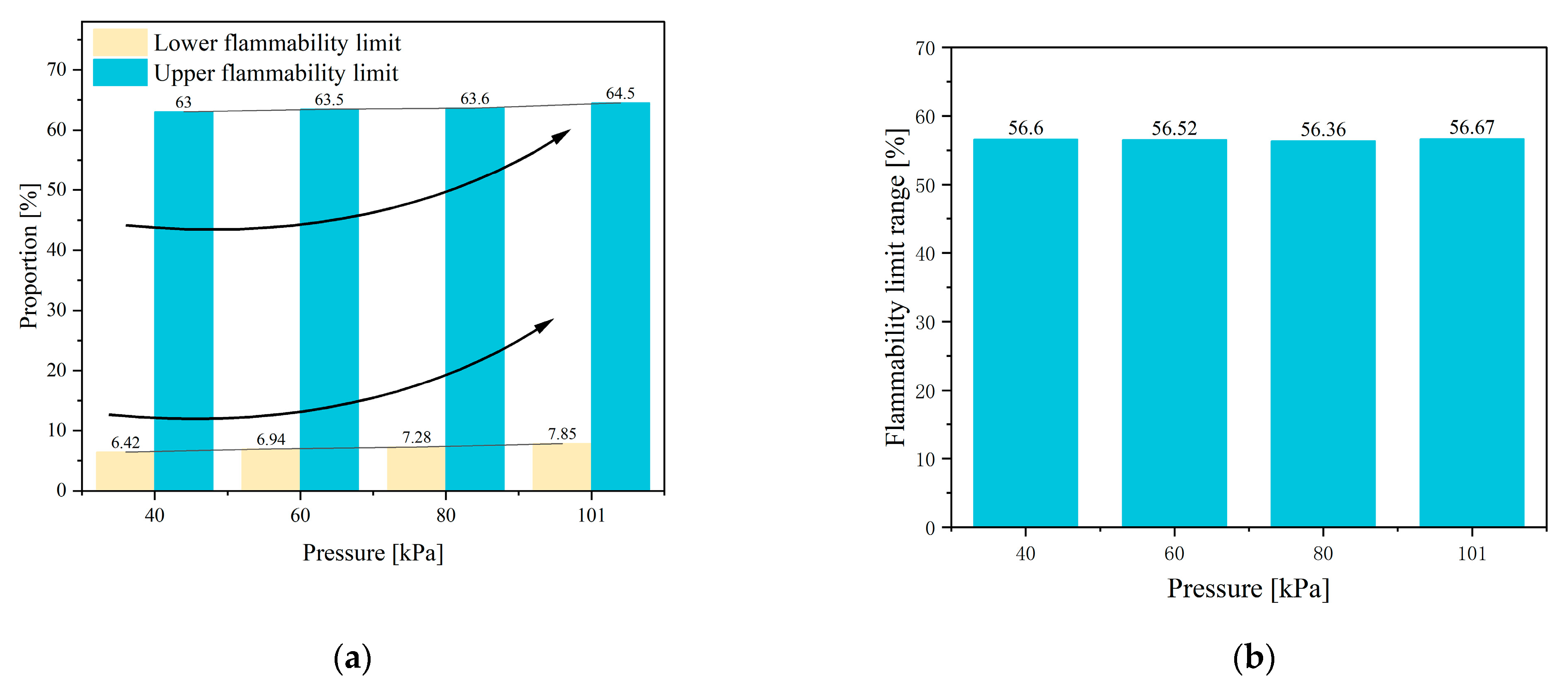
5.3. Flammability Characteristic

LEL refers to the lowest concentration at which a combustible mixture can explode. Due to the insufficient concentration of flammability, the cooling effect of excess air prevents the spread of the flame, so it neither explodes nor catches fire at levels below LEL. Therefore, the lower the LEL, the more dangerous, and the larger the flammability limit range, the more dangerous [37]. Figure 16 shows the changes in the LEL, UEL, and flammability limit range under four pressures.
According to Figure 16a, the LEL at 40kPa is 6.42% and the UEL is 63%. At 60kPa, the LEL is 6.94%, and the UEL is 63.5%. At 80kPa, the LEL is 7.28% and the UEL is 63.6%. At 101 kPa, the LEL is 7.85% and the UEL is 64.5%. The UEL values are sorted in ascending order as 40 kPa < 60 kPa < 80 kPa < 101 kPa, and the LEL values are sorted in ascending order as 40 kPa < 60 kPa < 80 kPa < 101 kPa. As shown in Figure 16b, at different chamber pressures, the flammability limit range basically does not change.

6. Safety Assessment

6.1. Methdology

The above research shows that the main parameters for characterizing battery safety include Ts, Tc, internal pressure of the battery, gas content, LEL, and TR trigger time. In order to comprehensively evaluate the risk of battery TR under four pressures, this paper refers to the maximum benchmark method to evaluate each characteristic. The evaluation method is shown in Equation (32). The scores of a characteristic under a certain pressure condition are calculated by dividing the value of the characteristic at this operating condition by the maximum value of the characteristic under the four operating conditions, and then multiplying by 100.
Scores = (Value/Max value) × 100
In terms of the triggering time for TR, a shorter triggering time indicates a higher level of danger. Therefore, the method described in Equation (33) is introduced for quantification.
Time Scores = 100 − [(Value − Min value)/Min value × 100]

6.2. Six Dimensional Radar Evaluation Results

As shown in Table 5, the allocation of six characteristic values under different pressure conditions is presented. The most dangerous characteristic is assigned a value of 100, with smaller numbers indicating relative safety. The average of the assigned values for the six characteristics is used to evaluate the risk of TR in a specific pressure for the battery.
To visually compare the TR risk under four different pressures, a hexagonal radar chart, as shown in Figure 17, is plotted for better illustration.

6.3. Sequence Analysis

Combining Table 5 and Figure 17, it can be seen that at 40 kPa, the area in Figure 17 is the largest. At the TR triggering time, internal pressure, LEL, and Ts are more dangerous than the other three chamber pressures, and the TR triggering time is far more dangerous than the other three chamber pressures. Tc at 80 kPa and 101 kPa is more dangerous than the other two pressures. The gas content is the highest at 80 kPa and the lowest at 60 kPa.
According to Table 5, the average scores in descending order are 40 kPa > 80 kPa > 101 kPa > 60 kPa. Therefore, it is considered that TR is most dangerous at 40 kPa, with an evaluation score far higher than those of the other three chamber pressures. Among the six characteristic parameters, four of them scored 100, indicating the most dangerous conditions. Next is the 80 kPa and 101 kPa, with one characteristic parameter scoring 100. Finally, for 60 kPa, none of the characteristic parameters were assigned a value of 100, indicating they are the safest.

7. Conclusions

This article compares the TR characteristics of batteries under different chamber pressures from the aspects of Ts, Tc, gas generation, topen, tTR, and gas composition, and draws the following conclusions.
  • The paper measures the TR characteristics at 40 kPa using temperature and pressure sensors. The results indicate that venting occurs twice during the TR process, with corresponding Tv of 163.3 °C and 245.9 °C, and corresponding chamber pressures of 55.3 kPa and 65.3 kPa.
  • At 40 kPa, gas chromatography analysis reveals that the highest proportion of H2 in the mixed gas is 55%, followed by CO2 at 18%, and then CO and CH4 at 11% and 10%, respectively. The LEL and UEL are calculated using the Le Chatelier formula and are found to be 6.42% and 63%, respectively.
  • The paper further investigates the effects of 40 kPa, 60 kPa, 80 kPa, and 101 kPa on the TR characteristics of the battery. It is found that chamber pressure significantly affects the peak of Ts, Tc, topen, tTR, Δt, gas composition, LEL, and UEL. Conversely, pressure has minimal impact on the internal pressure and gas generation rate of the battery.
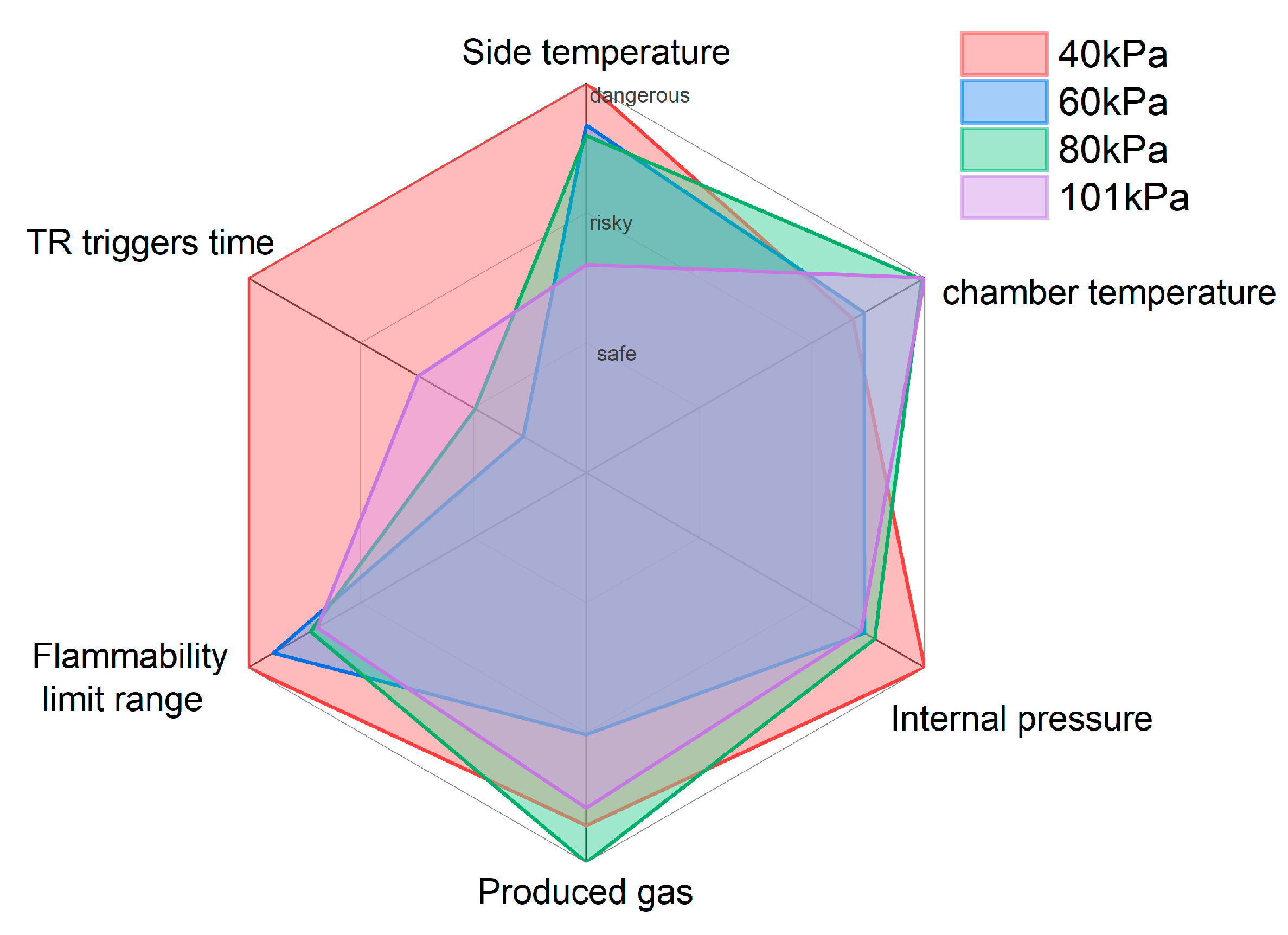
  • A six-dimensional radar chart analysis method is proposed to evaluate the danger of TR under different pressures. The results show that the most dangerous pressure is at 40 kPa, followed by 80 kPa and 101 kPa, while the 60 kPa is relatively safer.
  • At low pressure, it is found that topen and tTR are much shorter than that of the battery at normal pressure. Δt is significantly longer than that of the battery under normal pressure. It is recommended that designers use the opening sound of the safety valve or the gas concentration to catch the opening action quickly and take action at longer time intervals.
This study proposes a testing method with embedded pressure sensors and an evaluation method based on a six-dimensional radar chart. It analyzes the characteristics and mechanisms of TR under different pressure conditions, providing theoretical references for the safe use and TR warning of lithium-ion batteries in the high-altitude energy storage industry.

Author Contributions

Writing—original draft, Y.W. (Yu Wang); Methodology, Y.W. (Yan Wang); Investigation, J.Z., H.L. and F.D.; Conceptualization, C.X.; Formal analysis, Y.L.; Validation, H.W. and R.Y.; Data curation, L.L. and F.Q. All authors have read and agreed to the published version of the manuscript.

Funding

This research was funded by [National Natural Science Foundation of China] grant number [No. 52207240], [Shandong Province Science and Technology Foundation] grant number [No. ZR2022QE099], and [Shandong Province Excellent youth & innovation team Foundation] grant number [No. 2023KJ323]. And The APC was funded by [Tsinghua University].

Data Availability Statement

Data available on request due to restrictions eg privacy or ethical. The data presented in this study are available on request from the corresponding author. The data are not publicly available due to [due to our lab’s policies or confidentiality agreements, we cannot provide raw data. If editors and reviewers have questions about specific data, we will try to provide more detailed explanations and explanations].

Conflicts of Interest

As author Feng Dai was employed by Sichuan New Energy Vehicle Innovation Center Co., Ltd., the remaining authors declare that the research was conducted in the absence of any commercial or financial relationships that could be construed as a potential conflict of interest.

References

  1. Wang, Q.; Mao, B.; Stoliarov, S.I.; Sun, J. A review of lithium ion battery failure mechanisms and fire prevention strategies. Prog. Energy Combust. Sci. 2019, 73, 95–131. [Google Scholar] [CrossRef]
  2. Jia, Z.; Wang, S.; Qin, P.; Li, C.; Song, L.; Cheng, Z.; Jin, K.; Sun, J.; Wang, Q. Comparative investigation of the thermal runaway and gas venting behaviors of large-format LiFePO4 batteries caused by overcharging and overheating. J. Energy Storage 2023, 61, 106791. [Google Scholar] [CrossRef]
  3. Peng, Y.; Yang, L.; Ju, X.; Liao, B.; Ye, K.; Li, L.; Cao, B.; Ni, Y. A comprehensive investigation on the thermal and toxic hazards of large format lithium-ion batteries with LiFePO4 cathode. J. Hazard. Mater. 2020, 381, 120916. [Google Scholar] [CrossRef] [PubMed]
  4. Gyatso, N.; Li, Y.; Gao, Z.; Wang, Q.; Li, S.; Yin, Q.; Chen, J.; Jin, P.; Liu, Z.; Ma, Z.; et al. Wind power performance assessment at high plateau region: A case study of the wind farm field test on the Qinghai-Tibet plateau. Appl. Energy 2023, 336, 120789. [Google Scholar] [CrossRef]
  5. Ren, D.; Feng, X.; Liu, L.; Hsu, H.; Lu, L.; Wang, L.; He, X.; Ouyang, M. Investigating the relationship between internal short circuit and thermal runaway of lithium-ion batteries under thermal abuse condition. Energy Storage Mater. 2021, 34, 563–573. [Google Scholar] [CrossRef]
  6. Zhu, N.; Wang, X.; Chen, M.; Huang, Q.; Ding, C.; Wang, J. Study on the Combustion Behaviors and Thermal Stability of Aging Lithium-Ion Batteries with Different States of Charge at Low Pressure. PROCESS Saf. Environ. Prot. 2023, 174, 391–402. [Google Scholar] [CrossRef]
  7. Zhang, Q.; Liu, T.; Wang, Q. Experimental study on the influence of different heating methods on thermal runaway of lithium-ion battery. J. Energy Storage 2021, 42, 103063. [Google Scholar] [CrossRef]
  8. Feng, X.; Ouyang, M.; Liu, X.; Lu, L.; Xia, Y.; He, X. Thermal runaway mechanism of lithium ion battery for electric vehicles: A review. Energy Storage Mater. 2018, 10, 246–267. [Google Scholar] [CrossRef]
  9. Tran, M.-K.; Mevawalla, A.; Aziz, A.; Panchal, S.; Xie, Y.; Fowler, M. A Review of Lithium-Ion Battery Thermal Runaway Modeling and Diagnosis Approaches. Processes 2022, 10, 1192. [Google Scholar] [CrossRef]
  10. Li, Y.; Feng, X.; Ren, D.; Ouyang, M.; Lu, L.; Han, X. Thermal Runaway Triggered by Plated Lithium on the Anode after Fast Charging. ACS Appl. Mater. Interfaces 2019, 11, 46839–46850. [Google Scholar] [CrossRef]
  11. Guo, Q.; Zhang, J.; Zhou, C.; Huang, Z.; Han, D. Thermal Runaway Behaviors and Kinetics of NCM Lithium-Ion Batteries at Different Heat Dissipation Conditions. J. Electrochem. Soc. 2023, 170, 080507. [Google Scholar] [CrossRef]
  12. Xu, X.; Sun, X.; Zhao, L.; Li, R.; Tang, W. Research on thermal runaway characteristics of NCM lithium-ion battery under thermal-electrical coupling abuse. Ionics 2022, 28, 5449–5467. [Google Scholar] [CrossRef]
  13. Pastor, J.V.; García, A.; Monsalve-Serrano, J.; Golke, D. Analysis of the aging effects on the thermal runaway characteristics of Lithium-Ion cells through stepwise reactions. Appl. Therm. Eng. 2023, 230, 120685. [Google Scholar] [CrossRef]
  14. Li, Q.; Yang, C.; Santhanagopalan, S.; Smith, K.; Lamb, J.; Steele, L.A.; Torres-Castro, L. Numerical investigation of thermal runaway mitigation through a passive thermal management system. J. Power Sources 2019, 429, 80–88. [Google Scholar] [CrossRef]
  15. Qian, F.; Wang, H.; Li, M.; Li, C.; Shen, H.; Wang, J.; Li, Y.; Ouyang, M. Thermal Runaway Vent Gases from High-Capacity Energy Storage LiFePO4 Lithium Iron. Energies 2023, 16, 3485. [Google Scholar] [CrossRef]
  16. Chen, S.; Wang, Z.; Wang, J.; Tong, X.; Yan, W. Lower explosion limit of the vented gases from Li-ion batteries thermal runaway in high temperature condition. J. Loss Prev. Process. Ind. 2020, 63, 103992. [Google Scholar] [CrossRef]
  17. Zhang, Q.; Niu, J.; Yang, J.; Liu, T.; Bao, F.; Wang, Q. In-situ explosion limit analysis and hazards research of vent gas from lithium-ion battery thermal runaway. J. Energy Storage 2022, 56, 106146. [Google Scholar] [CrossRef]
  18. Baird, A.R.; Archibald, E.J.; Marr, K.C.; Ezekoye, O.A. Explosion hazards from lithium-ion battery vent gas. J. Power Sources 2020, 446, 227257. [Google Scholar] [CrossRef]
  19. Zhang, F.; Feng, X.; Xu, C.; Jiang, F.; Ouyang, M. Thermal runaway front in failure propagation of long-shape lithium-ion battery. Int. J. Heat Mass Transf. 2022, 182, 121928. [Google Scholar] [CrossRef]
  20. Huang, Q.; Weng, J.; Ouyang, D.; Chen, M.; Wang, X.; Wang, J. Comparative studies on the combustion characteristics of electrolytes and carbonate mixed solvents with flame retardant additives under low pressures. Case Stud. Therm. Eng. 2023, 43, 102810. [Google Scholar] [CrossRef]
  21. Zou, K.; Chen, X.; Ding, Z.; Gu, J.; Lu, S. Jet behavior of prismatic lithium-ion batteries during thermal runaway. Appl. Therm. Eng. 2020, 179, 115745. [Google Scholar] [CrossRef]
  22. Kang, R.; Jia, C.; Zhao, J.; Zhao, L.; Zhang, J. Effects of capacity on the thermal runaway and gas venting behaviors of large-format lithium iron phosphate batteries induced by overcharge. J. Energy Storage 2024, 87, 111523. [Google Scholar] [CrossRef]
  23. Wang, Z.; Jiang, X.; Ke, W.; Wang, W.; Zhang, S.; Zhou, B. Effect of lithium-ion battery diameter on thermal runaway propagation rate under one-dimensional linear arrangement. Therm. Sci. Eng. Prog. 2022, 31, 101301. [Google Scholar] [CrossRef]
  24. Liu, Y.; Niu, H.; Liu, J.; Huang, X. Layer-to-layer thermal runaway propagation of open-circuit cylindrical li-ion batteries: Effect of ambient pressure. J. Energy Storage 2022, 55, 105709. [Google Scholar] [CrossRef]
  25. Li, Y.; Jiang, L.; Huang, Z.; Jia, Z.; Qin, P.; Wang, Q. Pressure Effect on the Thermal Runaway Behaviors of Lithium-Ion Battery in Confined Space. Fire Technol. 2023, 59, 1137–1155. [Google Scholar] [CrossRef]
  26. Liu, Q.; Zhu, Q.; Zhu, W.; Yi, X.; Han, X. Thermal Runaway Characteristics of 18650 NCM Lithium-ion Batteries under the Different Initial Pressures. Electrochemistry 2022, 90, 087004. [Google Scholar] [CrossRef]
  27. Ding, C.; Zhu, N.; Yu, J.; Li, Y.; Sun, X.; Liu, C.; Huang, Q.; Wang, J. Experimental investigation of environmental pressure effects on thermal runaway properties of 21700 lithium-ion batteries with high energy density. Case Stud. Therm. Eng. 2022, 38, 102349. [Google Scholar] [CrossRef]
  28. Sun, Q.; Liu, H.; Zhi, M.; Chen, X.; Lv, P.; He, Y. Thermal characteristics of thermal runaway for pouch lithium-ion battery with different state of charges under various ambient pressures. J. Power Sources 2022, 527, 231175. [Google Scholar] [CrossRef]
  29. Zhao, J.; Feng, X.; Tran, M.-K.; Fowler, M.; Ouyang, M.; Burke, A.F. Battery safety: Fault diagnosis from laboratory to real world. J. Power Sources 2024, 598, 234111. [Google Scholar] [CrossRef]
  30. Qiu, M.; Liu, J.; Cong, B.; Cui, Y. Research Progress in Thermal Runaway Vent Gas Characteristics of Li-Ion Battery. Batteries 2023, 9, 411. [Google Scholar] [CrossRef]
  31. Zhang, Y.; Wang, H.; Wang, Y.; Li, C.; Liu, Y.; Ouyang, M. Thermal abusive experimental research on the large-format lithium-ion battery using a buried dual-sensor. J. Energy Storage 2021, 33, 102156. [Google Scholar] [CrossRef]
  32. Song, L.; Zheng, Y.; Xiao, Z.; Wang, C.; Long, T. Review on Thermal Runaway of Lithium-Ion Batteries for Electric Vehicles. J. Electron. Mater. 2022, 51, 30–46. [Google Scholar] [CrossRef]
  33. Sun, Y.; Jin, Y.; Jiang, Z.; Li, L. A review of mitigation strategies for li-ion battery thermal runaway. Eng. Fail. Anal. 2023, 149, 107259. [Google Scholar] [CrossRef]
  34. Shen, H.; Wang, H.; Li, M.; Li, C.; Zhang, Y.; Li, Y.; Yang, X.; Feng, X.; Ouyang, M. Thermal Runaway Characteristics and Gas Composition Analysis of Lithium-Ion Batteries with Different LFP and NCM Cathode Materials under Inert Atmosphere. Electronics 2023, 12, 1603. [Google Scholar] [CrossRef]
  35. Ohsaki, T.; Kishi, T.; Kuboki, T.; Takami, N.; Shimura, N.; Sato, Y.; Sekino, M.; Satoh, A. Overcharge reaction of lithium-ion batteries. J. Power Sources 2005, 146, 97–100. [Google Scholar] [CrossRef]
  36. Wang, H.; Du, Z.; Liu, L.; Zhang, Z.; Hao, J.; Wang, Q.; Wang, S. Study on the Thermal Runaway and Its Propagation of Lithium-Ion Batteries Under Low Pressure. Fire Technol. 2020, 56, 2427–2440. [Google Scholar] [CrossRef]
  37. Yu, R.; Liu, J.; Liang, W.; Law, C.K.; Wang, H.; Ouyang, M. On flammability limits of battery vent gas: Role of diffusion, radiation and chemical kinetics. Combust. Flame 2023, 249, 112631. [Google Scholar] [CrossRef]
Figure 1. (a) Experimental flow chart. (b) Experimental chamber. (c) Battery changes after thermal runaway experiment. (d) Data collection. (e) GC analysis.
Batteries 10 00270 g001
Figure 2. Battery embedded sensor method.
Batteries 10 00270 g002
Figure 3. TR experimental diagram.
Batteries 10 00270 g003
Figure 4. Feature temperatures at 40 kPa. (a) Battery safety valve temperature; (b) temperature rise rate of valve; (c) center temperature of battery side; (d) center temperature of chamber.
Batteries 10 00270 g004
Figure 5. Internal and chamber pressure. (a) Battery internal pressure and pressure difference; (b) chamber pressure and valve temperature.
Batteries 10 00270 g005
Figure 6. Gas composition distribution at 40 kPa.
Batteries 10 00270 g006
Figure 7. Gas venting characteristics at 40 kPa. (a) Molar of gas; (b) mass of gas; (c) volume of gas.
Batteries 10 00270 g007
Figure 8. Side temperature comparison. (a) Side center temperature; (b) peak temperature.
Batteries 10 00270 g008
Figure 9. Comparison of the central temperature in chamber. (a) Temperature in center of chamber; (b) peak temperature.
Batteries 10 00270 g009
Figure 10. The internal pressure. (a) Internal pressure change; (b) peak internal pressure.
Batteries 10 00270 g010
Figure 11. The chamber pressure. (a) Pressure changes in chamber; (b) peak pressure changes.
Batteries 10 00270 g011
Figure 12. The pressure difference. (a) Pressure difference; (b) Peak pressure difference.
Batteries 10 00270 g012
Figure 13. The key time of TR.
Batteries 10 00270 g013
Figure 14. Comparison of gas content.
Batteries 10 00270 g014
Figure 15. The proportion of gases at different pressures.
Batteries 10 00270 g015
Figure 16. Flammability limit of mixture. (a) UEL and LEL; (b) flammability limit range.
Batteries 10 00270 g016
Figure 17. Comparison of radar charts in different pressures.
Batteries 10 00270 g017
Table 1. Basic parameters of the sample battery.
ParametersValue
Weight5.34 ± 0.3 kg
End of charge voltage3.65 V
End of discharge voltage2.5 V
Specific heat1029.49 J/(kg∙°C)
Table 2. Characteristics of TR in different stages.
Stage
Time (s)0–800800–958958–12201220–14931493–2000
Basic features1. Heating period.
2. Tv and Tc increase slowly.
1. The safety valve opens.
2. Tv increases dramatically, and the first crest occurs, respectively.
1. TR is triggered.
2. Tv and Tc increase dramatically, and the second crest occurs, respectively.
1. The second venting occurs.
2. Tv and Tc decrease after the third peak.
1. Cooling stage.
2. The temperature
drops.
Temperature range (°C)Tv26.6–54 °C49.6–74.6 °C49.6–176.2 °C141.8–245.9 °C
Ts112.7–138.4 °C112.7–140.9 °C136.3–302.8 °C242.1–254.5 °C
Tc27–37 °C37–42.9 °C37.4–63.1 °C63–90.4 °C
Table 3. Gas flammability limits table.
ParameterLEL (%)UEL (%)
H2475
CO12.574
CH4515
C2H42.736
Mixed gas6.4263
Flammability limit range56.6
Table 4. Change rate of the gas content.
Parameter406080101
The first peakValue (mol/s)0.090.060.10.38
Time (s)831145614111336
The second peakValue (mol/s)0.140.10.06\
Time (s)101216381455\
The third peakValue (mol/s)0.070.040.06\
Time (s)122817781520\
Table 5. Scores of each characteristic quantity.
Parameter40 kPa60 kPa80 kPa101 kPa
Side temperature [°C]10093.591.972
Chamber temperature [°C]87.389.399.5100
Internal pressure [kPa]10092.994.192.5
Gas content [mol]94.380.310091.6
Lower flammable limit [%]1009286.677.7
TR triggers time [s]10051.259.769.8
Average scores96.983.288.683.9
Disclaimer/Publisher’s Note: The statements, opinions and data contained in all publications are solely those of the individual author(s) and contributor(s) and not of MDPI and/or the editor(s). MDPI and/or the editor(s) disclaim responsibility for any injury to people or property resulting from any ideas, methods, instructions or products referred to in the content.

