Article

Improving LiFe0.4Mn0.6PO4 Nanoplate Performance by a Dual Modification Strategy toward the Practical Application of Li-Ion Batteries

1
Global R&D Center, Guangxi Liugong Machinery Co., Ltd., Liuzhou 545007, China
2
International Iberian Nanotechnology Laboratory (INL), Avenida Mestre Jose Veiga, 4715-330 Braga, Portugal
*
Authors to whom correspondence should be addressed.
Batteries 2024, 10(8), 272; https://doi.org/10.3390/batteries10080272
Submission received: 2 July 2024 / Revised: 17 July 2024 / Accepted: 24 July 2024 / Published: 29 July 2024

Abstract

:
A novel composite consisting of fluorine-doped carbon and graphene double-coated LiMn0.6Fe0.4PO4 (LMFP) nanorods was synthesized via a facile low-temperature solvothermal method that employs a hybrid glucose and polyvinylidene fluoride as carbon and fluorine sources. As revealed by physicochemical characterization, F-doped carbon coating and graphene form a ‘point-to-surface’ conductive network, facilitating rapid electron transport and mitigating electrochemical polarization. Furthermore, the uniform thickness of the F-doped carbon coating alters the growth of nanoparticles and prevents direct contact between the material and the electrolyte, thereby enhancing structural stability. The strongly electronegative F can inhibit the structural changes in LMFP during charge/discharge, thus reducing the Jahn–Teller effect of Mn3+. The distinctive architecture of the LMFP/C-F/G cathode material exhibits excellent electrochemical properties, exhibiting an initial discharge capacity of 163.1 mAh g−1 at 0.1 C and a constant Coulombic efficiency of 99.7% over 100 cycles. Notably, the LMFP/C-F/G cathode material achieves an impressive energy density of 607.6 Wh kg−1, surpassing that of commercial counterparts. Moreover, it delivers a reversible capacity of 90.3 mAh g−1 at a high current rate of 5 C. The high-capacity capability and energy density of the prepared materials give them great potential for use in next-generation lithium-ion batteries.

1. Introduction

The enhancement of lithium-ion battery performance relies significantly on the positive electrode material [1,2]. Therefore, the study of positive electrode materials is crucial in both scientific and industrial fields. Among them, the olivine-type structure of polyanionic phosphate positive electrode materials is considered to have immense potential for development, owing to its excellent performance [3]. In 1997, Goodenough et al. [4] discovered that lithium iron phosphate (LFP) material possesses lithium-insertion/extraction properties, garnering significant attention as a polyanionic LiMPO4 (M=Fe, Mn, Ni, Co, etc.) cathode material. Notably, with a tetrahedral PO43− polyanion structure, the P–O bond exhibits strong covalency [5]. This not only prevents the release of oxygen release but also stabilizes the ionic covalency of the M(3d)–O(2p) bond through inducing effects, thereby enhancing the stability of LiMPO4 [6]. Among developed LiMPO4 materials, LFP has undergone rapid industrialization, owing to its advantages such as prolonged cycle life, high safety, and low cost [7,8]. However, LFP material still encounters limitations: First, it exhibits lower electronic and ionic conductivity at room temperature than lithium cobalt and lithium manganate [9]. Second, the energy density of the LFP cathode material (578 Wh kg−1) nears its limit owing to its low operating voltage (3.4 V vs. Li+/Li) and theoretical capacity (170 mAh g−1), which makes it difficult to meet the growing demands for high energy and long-term endurance in electric vehicles [10]. Consequently, improving its electron/ion conductivity and energy density has become paramount.
In recent years, a LiMnxFe1−xPO4 (0 ≤ x ≤ 1) material with high energy density has been considered an upgraded version of LFP [11,12]. Studies have shown that constructing a structure with x = 0.6 is the most suitable scheme for attaining the optimal rate capability and energy density [13,14]. However, the practical application of LMFP encounters challenges, such as weak electron transport and Li+ diffusion ability, and structural instability due to Mn3+ dissolution [15,16]. To address these issues, research on LMFP has focused on modifying both external surfaces and internal structures. External surface modification typically involves applying a barrier layer onto the olivine structure to enhance the electronic/ionic conductivity of the material, while reducing the contact area between the main material and the electrolyte to effectively inhibit electrolyte decomposition and improve cycling stability [17,18]. Additionally, this process can partially suppress the Jahn–Teller effect by applying additional pressure on the internal crystals through the surface coating, thereby reducing the probability of microcrack formation. Internal structure modification focuses on controlling the crystal size [19,20], regulating crystal structure order [21,22], and achieving a specific distribution of Mn/Fe atoms [23,24] to accelerate electrochemical activity and enhance battery performance. Therefore, deliberately controlling the crystal growth conditions to produce high-quality LiMn0.6Fe0.4PO4 cathode materials is crucial for promoting its commercial application.
Compared to the solid-phase method, hydrothermal synthesis represents a feasible strategy for effectively controlling crystal growth at the atomic level [8]. Nucleation and crystal growth can be controlled by adjusting the temperature, reaction time, and heating rate [25]. Furthermore, different solvents provide options for controlling the crystallinity and nanomorphology [26]. Many hydrothermal synthesis methods currently achieve excellent performance materials at high temperatures (approximately 180 °C), which are not conducive to industrial production and management. Therefore, developing a low-temperature synthesis method for LMFP industrialization is important.
In this study, we employed an environmentally friendly and efficient low-temperature solvothermal reaction to synthesize the nanorod-like LiMn0.6Fe0.4PO4 (LMFP) cathode material with enhanced electrochemical reaction kinetics. We investigated the effects of the crystallinity, orientation, morphology, particle size, and electrochemical properties of LMFP. Because of the low electronic conductivity of the synthesized LMFP sample, we used doping and carbon coating modifications to enhance its electrochemical performance [27]. Previous studies have demonstrated that doping with the highly electronegative F element can effectively enhance lithium-ion adsorption and promote electrode reactions [28]. In addition, the carbon-coated and graphene-constructed ‘point-to-surface’ combined network structure provides rapid channels for electron and ion transport [29]. Consequently, LMFP/C-F/G materials exhibit high capacity, excellent rate performance, and high energy density, providing a strong foundation for the commercial application of LMFP.

2. Experimental Section

2.1. Chemicals

The chemicals used in the experiment were as follows: Phosphoric acid (H3PO4, AR, 85%, Aladdin, Shanghai, China); lithium hydroxide monohydrate (LiOH·H2O, AR, Aladdin); manganese (II) sulfate monohydrate (MnSO4·4H2O, AR, 99.0%, Aladdin); iron (II) sulfate heptahydrate (FeSO4·7H2O, AR, 99.5%, Aladdin); L(+)-ascorbic acid (C6H8O6, AR, 99.99%, Sigma, St. Louis, MO, USA); N, N-Dimethylformamide (DMF, AR, 99.5 wt.%, Ghtech, Shantou, China); glucose (G116300, AR, 99.5%, Aladdin); graphene (SE1232, purchased from The Sixth Element (Changzhou) Material Technology Co., Ltd., Changzhou, China); Poly(vinylidene fluoride) (PVDF, P432380, Aladdin); N-methyl-2-pyrrolidone (NMP, Aladdin); and Ultrapure water (18.2 MΩ·cm @ 25 °C), which was produced by a Millipore System (LICHEN UPTA-20, China). All chemicals were used without any further purification.

2.2. Material Synthesis

Synthesis of LiMn0.6Fe0.4PO4: Typically, the cathode materials were synthesized via the solvothermal method. LiOH·H2O, MnSO4·H2O, FeSO4·7H2O, and H3PO4 (mass fraction 85%) were used as raw materials, and the molar ratio was 3:0.6:0.4:1, respectively. L(+)-ascorbic acid was used as an antioxidant. The solvent was a mixture of DMF and water, in a solvent ratio of VDMF/VH2O = 1 (60 mL in total).
Firstly, 30 mmol LiOH·H2O and 10 mmol H3PO4 were added to the solvent, the raw materials were fully dissolved by an ultrasonic machine, and the white suspended substance Li3PO4 was formed after reacting for 1.5 h. Then a certain amount of manganese source, iron source, and L(+)-ascorbic acid were added to the solvent, and the raw materials were fully dissolved by ultrasound. The above two solutions were mixed thoroughly and transferred to a 100 mL Teflon lined autoclave for solvothermal reaction in a blower (heating rate of 5 °C/min, kept at 100 °C for 48 h). Finally, the ash black precursor powder LiMn0.6Fe0.4PO4 was obtained after centrifugation and drying, denoted as LMFP.
Synthesis of LMFP/C: For LMFP/C, the mass of glucose added accounted for 10 wt.% of the precursor LMFP and was fully mixed and ground. Then, it was calcined at 650 °C for 8 h in an inert atmosphere (Ar, 99.999%) at a rate of 5 °C/min. Finally, the samples were collected and named LMFP/C.
Synthesis of LMFP/C/G: For LMFP/C-G, the synthesis steps were the same as for LMFP/C, the only difference was that only graphene was added, and it was named LMFP/C/G.
Synthesis of LMFP/C-F/G: For LMFP/C-F/G, the synthesis steps were the same as those for LMFP/C-F/G, the only difference was that only PVDF was added as the F source, and it was named LMFP/C-F/G.
Some experiments have indicated that the rate performance enhancement of samples prepared by directly coating graphene on the surface of cathode materials using the hydrothermal method is unsatisfactory, potentially due to stacking or destruction of the graphene material structure [30]. Moreover, complete coating results in a decrease in ion transport efficiency, which is hypothesized to be caused by lithium ions being unable to pass through the six-membered ring structure of graphene [31,32]. Given the above, we developed a ‘point-to-surface’ conductive network where the graphene exists in a partially coated state. This design facilitates rapid lithium-ion transport and enhances conductivity (as illustrated in Scheme 1). The mechanism involves incorporating graphene material between the LMFPs in a layered structure, similar to building a ‘bridge’ for electron conduction.

3. Results and Discussion

The crystal structure of the prepared cathode materials was identified by X-ray diffraction (XRD). As depicted in Figure 1, the diffraction peaks at 16.9°, 20.7°, 22.5°, 25.4°, 29.5°, 32.0°, 35.3°, 36.3°, 37.6°, 39.3°, 42.0°, 48.9°, 50.4°, 52.2°, 54.9°, 56.4°, 57.9°, 61.3°, 69.6°, 72.0°, and 74.0° correspond to the (020), (011), (120), (111), (200), (031), (131), (211), (140), (221), (112), (202), 151), (321), (160), (061), (340), (152), (223), (440), and (271) planes of the standard diffraction peak of orthorhombic Pmnbs (LMFP: PDF#11-0456) for both LMFP/C, LMFP/C/G, and LMFP/C-F/G, respectively, indicating that all carbon-coated and doped materials were pure phase. Furthermore, the sharp diffraction peaks indicated a high crystallinity intensity for the three LMFP materials, with the highest diffraction peak located in the (131) crystal plane. The presence of an additional diffraction peak is not observed, indicating that the lattice structure of LMFP/C remained intact despite the slight F-doping and trace graphene introduction [27]. Notably, no diffraction peaks of carbon were found either, indicating the possible formation of amorphous carbon, which was subsequently confirmed by TEM characterization. Moreover, no graphene (002) diffraction peak was found because the low content of graphene and the strong LFMP (111) diffraction peak occurred at the same 2θ angle [33].
Transmission electron microscopy (TEM) was used to investigate the effects of F-doping and coating strategies on the microstructure and morphology of LMFP/C-F/G materials. As shown in Figure 2a,b, LMFP/C-F/G exhibits a nanorod morphology with a length of 50–400 nm and a width of 40–80 nm, which is consistent with the observations from scanning electron microscopy (SEM) images (Figure S1). In addition, it is evident that the carbon coating material and graphene constitute a ’point-to-surface’ conductive network, which significantly enhances the electronic conductivity of the LMFP material. The excellent electrochemical performance of LMFP/C-F/G could be attributed to the successful synthesis of the hierarchical and bridging structure. This structure ensures a consistent coating of amorphous carbon tightly linked with the high electrical conductivity facilitated by graphene.
To determine the large, exposed surface, internal structure, and lattice growth mechanisms of the LMFP/C-F/G nanorods, the material was deeply characterized using high-resolution TEM (HRTEM). The underlined part is the amorphous carbon with a thickness of approximately 4.0 nm, formed by the carbonation of the added glucose and PVDF (Figure 2c,d), which was observed on the surface of the particles. This uniform coating of amorphous carbon plays a crucial role in inhibiting further crystal growth during sintering and enhancing the electronic conductivity of the material. On the one hand, these amorphous carbons improve the conductivity of the LMFP material; on the other hand, they prevent the increase in the size of the LMFP nanoparticles and inhibit the dissolution of Mn. Furthermore, it is shown in Figure 2h that well-resolved lattice fringes with a d-spacing of 0.349 nm, which correspond to the (111) lattice plane of LMFP.
Elemental mapping results are shown in Figure 2e–g,i–l; it is seen that the C, O, Mn, Fe, F, and P elements are uniformly distributed over the LMFP nanoparticle. This observation signifies the successful doping of element F into the material, thereby imparting excellent electronic conductivity to it.
X-ray photoelectron spectroscopy (XPS, Figure 3, Figures S2 and S3) is utilized to investigate the elemental composition and chemical state present on a material’s surface [34]. All of the binding energy of the spectra was calibrated by utilizing the reference peak at 284.6 eV for C 1s. The survey spectrum of LMFP/C-F/G exhibited signals of Li 1s, C 1s, O 1s, F 1s, Fe 2p, Mn 2p, and P 2p elements (Figure 3). The content of the elements is summarized in Table 1, and it can be found that the molar ratio of Fe/Mn is approximately 4/6, which corresponds to the feeding ratio.
High-resolution XPS spectra revealed that the Fe 2p spectrum (Figure 3b) is split into two peaks at about 710.9 and 724.3 eV, which correspond to Fe 2p3/2 and Fe 2p1/2, respectively [35]. The results confirm that the oxidation state of Fe is 2+. Additionally, two peaks at energies of around 712.8 and 727.5 eV are identified as satellite features related to Fe2+ [36].
As shown in Figure 3c, the Mn 2p spectrum is split into two peaks at approximately 640.9 and 653.0 eV, which can be ascribed to Mn 2p3/2 and Mn 2p1/2, respectively. The results confirm that the oxidation state of Mn is 2+ [37]. The high-resolution XPS spectrum of the C 1s can be fitted into three peaks (Figure 3d). The dominant binding energy located at 284.6 eV is ascribed to the existence of the C-C bond. The peak located at about 286.1 eV corresponds to the C-O bond configuration [38]. In addition, the peak at approximately 288.5 eV is ascribed to the existence of O=C-O or a C-F chemical bond [39]. The peaks located at about 132.6 and 530.6 eV are ascribed to P 2p and O 1s, which belong to tetrahedral PO43− groups (Figure 3e,f). As shown in Figure 3g, two weak peaks located at about 685.4 and 687.5 eV belong to F-Mn and F-C chemical bonds, respectively [40]. This result suggests that F atoms are doped in the carbon coating; it not only acts as a lithium reservoir to stabilize the electrode but also as a composite current collector to manage the nucleation/growth of lithium [41], which is advantageous for reducing the charge transfer resistance and inhibiting the Jahn–Teller effect. The binding energy is divided into two fitted peaks in the 52–60 eV region, corresponding to the oxidation state of Li (Figure 3h). These results provide compelling evidence for the successful synthesis of the LMFP/C-F/G cathode material.

3.1. Electrochemical Performance and Analysis

Cyclic voltammogram (CV) and electrochemical impedance spectroscopy (EIS) were used to investigate the effect of F-doping and carbon coating on the electrochemical properties, electronic conductivity, and electrode kinetic parameters of LMFP (Figure 4). Figure 4a illustrates the CV diagram of three LMFP materials prepared under 1.0 mV s−1. The cyclic voltammetry curves have two pairs of distinct peaks near 3.5 V and 4.1 V, which correspond to the redox peaks of Fe2+/Fe3+ and Mn2+/Mn3+, respectively. The trend of the peak width of the three materials is the same, but the peak and peak sharpness are different. As shown in Table 2, the voltage difference between oxidizing and reducing peaks of LMFP/C-F/G is the smallest of all the samples (for the manganese site, LMFP/C-F/G (0.36 V) < LMFP/C/G (0.40 V) < LMFP/C (0.56 V), and for the iron site, LMFP/C-F/G (0.25 V) < LMFP/C/G (0.27 V) < LMFP/C (0.45 V), respectively). This may be due to the introduction of trace amounts of fluorine and graphene which promotes the transport of Li+ and reduces the polarization of the cathode. In addition, the peak shape of the LMFP/C-F/G electrode is sharper, indicating that it has faster reaction kinetics, which also match its excellent Li+ diffusion rate and optimal performance.

3.2. Mechanism Analysis of the Electrocatalytic Activity Enhancement

The electrochemical kinetics of the cathode material were further investigated by performing electrochemical impedance spectroscopy (EIS) measurements after CV cycling. The Nyquist plots (Figure 4b) present a compressed semicircle in a high-to-medium frequency and an oblique line in a low frequency. The intercept with the Z′ axis in the high-frequency region is associated with ohmic resistance (Rs), which describes the total resistance between the cathode material, separator, and electrolyte [42]. The following semicircle in the high- and middle-frequency regions refers to the charge transfer resistance (Rct), which describes the resistance of the electrochemical reaction at the electrolyte/electrode interface. The oblique line in the low-frequency region reflects Warburg impedance, which is associated with Li-ion diffusion in the cathode material particles [43]. By comparing the diameters of semicircles, it can be inferred that the LMFP/C-F/G cathode exhibits lower charge transfer resistance compared to LMFP/C/G and LMFP/C (Figure 4b), suggesting improved charge transfer kinetics and ionic conductivity resulting from the co-modification of F-doping and the carbon–graphene network.
To further investigate the electrochemical kinetics of the cathode material, we tested the CV at different sweep speeds and performed a fitting analysis. Figure 5 shows the CV curves of cathodes LMFP/C-F/G, LMFP/C/G, and LMFP/C at different scanning rates and the corresponding linear fitting between Ip and v1/2. It can be noticed that as the scanning rate increases, there is a gradual increase in the peak current. Compared to other cathodes, the cathode LMFP/C-F/G has a larger peak current and integration area, and better symmetry of the redox curve, which indirectly indicates a better performance. As shown in Equation (1), the lithium-ion diffusion coefficient DLi+ of the cathode material was calculated from the Randles–Sevcik formula [44,45].
Ip = 2.69 × 10⁵ n3/2AD1/2Cv1/2
where Ip is the peak current (A), n is the number of electrons transferred by the material during the electrochemical reaction, A is the specific surface area of the electrode active material (cm2), D is the Li-ion diffusion coefficient in LMFP at 298 K (cm2 s−1), C is the molar concentration of Li ions in the cathode material (0.0223 mol cm−3), and v is the scan rate (V s−1).
According to the formula, it can be observed that under identical conditions for other variables, the diffusion rate of lithium-ion DLi+ is positively correlated with the peak current intensity. Based on the slope analysis, it can be inferred that the LFMP/C-F/G cathode material exhibits a significantly higher lithium-ion diffusion rate compared to other materials (Figure 5). Specifically, by comparing the slope of the Mn site and the Fe site (Figure 5a’–a’’,b’–b’’,c’–c’’), it is qualitatively reasoned that the F-doped carbon layer can enhance the rate of Li+ insertion/extraction into/from LMFP, i.e., the DLi+ of the LMFP/C-F/G cathode is greater than those of LMFP/C/G and LMFP/C cathodes. Furthermore, the linear relationship suggests that the intercalation and deintercalation behavior of Li+ in the three materials are diffusion-controlled [11]. According to the slopes of the fitting lines in Figure 5, the Li-ion chemical diffusion coefficients of LMFP/C, LMFP/C/G, and LMFP/C-F/G are calculated to be 3.48 × 10⁻¹⁴, 5.81 × 10⁻¹⁴, and 1.20 × 10⁻¹³ cm2 s−1, respectively (Table S2). The LMFP/C-F/G sample shows the largest Li-ion diffusion rate, endowing it with the best rate performance.
Figure 6 illustrates the effects of carbon coating and F-doping on the electrochemical performance of LMFP/C-F/G at 25 °C, including the first charge/discharge, rate performance, cycle performance, etc. As shown in Figure 6a, after several activations, their charge/discharge curves basically coincide, indicating that their Coulomb efficiency is basically close to 100% and the material has good electrochemical stability.
In these curves, two pairs of obvious platforms appear near 3.5 V and 4.1 V, corresponding to the oxidation–reduction potentials of Fe2+/Fe3+ and Mn2+/Mn3+, respectively, and the ratio of the platforms is approximately 6/4, which is matched with the ratio of Mn/Fe in the material. This result is also in agreement with the results of the CV curves. It is worth noting that the first discharge capacities of LMFP/C-F/G materials were 163.1 mAh g−1 at the rate of 0.1 C, higher than LMFP/C/G (156.8 mAh g−1, Figure S4a) and LMFP/C (146.7 mAh g−1, Figure S5a, Table S1). Furthermore, benefiting from the increase in its voltage and capacity, the energy density of LMFP/C-F/G (607.6 Wh kg−1) was also significantly higher compared to that of LMFP/C/G (583.1 Wh kg−1) and LMFP/C (550.5 Wh kg−1) (Table S1). It is suggested that the construction of a ‘point-to-surface’ combined conductive network is advantageous in improving the performance and energy density of LMFP.
As presented in Figure 6b,c, the discharge capacity of the LMFP/C-F/G sample decreased as the C rates increased and the difference in capacity became progressively more pronounced at higher rates. It is worth noting that LMFP/C-F/G delivers discharge capacities of 163.1, 155.4, 146.7, 130.1, 114.6, and 88.1 mAh g−1 at 0.1, 0.2, 0.5, 1, 2, and 5 C, respectively. However, LMFP/C-/G only exhibits discharge capacities of 157.8, 146.3, 135.4, 119.6, 107.5, and 81.2 mAh g−1 at 0.1, 0.2, 0.5, 1, 2, and 5 C, respectively (Figure S4b and Table S1). LMFP/C only exhibits discharge capacities of 146.7, 142.8, 132.6, 118.2, 101.2, and 78.9 mAh g−1 at 0.1, 0.2, 0.5, 1, 2, and 5 C, respectively (Figure S5b and Table S1). Therefore, the rate capability of LMFP/C-F/G is significantly enhanced by the synergistic effect of the carbon coating and F-doping dual strategies. Figure 6d shows the cycle stability of LMFP/C-F/G at a rate of 0.1C. After 50 cycles of charge and discharge, the capacity retention rate is more than 95.3%. After 100 cycles, the capacity retention rate remains above 85.8%. These results indicate that the material exhibits good cyclic performance in the coin battery. Furthermore, even after hundreds of cycles, the Coulomb efficiency remains at about 99.5%.
To further compare the charge/discharge performance and rate performance of the three samples, we summarized these findings in Figure 7a,b. It can be seen that the discharge performance and rate performance of LMFP/C-F/G samples are significantly better than those of the other two materials. The remarkable performance of the LMFP/C-F/G cathode material can be attributed to various factors: (1) nano-crystallization and a well-defined, uniform morphology; (2) enhanced electronic conductivity achieved through a combination of mixed carbon sources and uniform coating; (3) the establishment of a rapid ion/electron conduction network, characterized by a ‘point-to-surface’ architecture; and (4) improved electrochemical kinetics facilitated by regulation through anion doping.

4. Conclusions

In summary, novel composite LMFP nanorods coated by F-doped carbon and graphene, forming a ‘point-to-surface’ conduction electron/ion network (LMFP/C-F/G), were successfully synthesized through a facile solvothermal reaction followed by a one-step calcination process. XRD and XPS characterization results demonstrate that the LMFP solid solution material was successfully synthesized. In addition, HRTEM characterization confirms that F was successfully doped into the material, and the surface was uniformly covered with a 4 nm thick layer of amorphous carbon, which greatly reduces the charge transfer resistance and decreases polarization. Its unique electronic structure endows the material with rapid lithium-ion diffusion and electron transport capabilities, resulting in excellent electrochemical performance in terms of specific capacity, rate capability, and cycle life. It exhibits an impressive discharge capacity of 163.1 mAh g−1 at a current rate of 0.1 C, with a Coulomb efficiency of 99.5% over 100 cycles. Moreover, it achieves an energy density as high as 607.6 Wh kg−1, which surpasses that of most similar materials including commercial lithium iron phosphate. These results further demonstrate that the electrochemical performance of lithium manganese phosphate can be effectively improved through a dual strategy of carbon coating and F-doping.

5. Patents

Application number: 202410340091.7.

Supplementary Materials

The following supporting information can be downloaded at: https://www.mdpi.com/article/10.3390/batteries10080272/s1, Experimental section; Figure S1: (a,b) SEM image of the LMFP/C-F/G nanorods and (c,d) graphene, Figure S2: (a) XPS survey spectra of LFMP/C and the high-resolution spectrum of (b) Fe 2p; (c) Mn 2p; (d) C 1s; (e) O 1s; (f) P 2p; (g) Li 1s, Figure S3: (a) XPS survey spectra of LFMP/C/G and the high-resolution spectrum of (b) Fe 2p; (c) Mn 2p; (d) C 1s; (e) O 1s; (f) P 2p; (g) Li 1s, Figure S4: Electrochemical performance of LMFP/C/G at 25 °C: (a) First three charge/discharge profiles at 0.1 C; (b) Rate performance at different C rates and (c) Corresponding charge/discharge curves, Figure S5: Electrochemical performance of LMFP/C at 25 °C: (a) First three charge/discharge profiles at 0.1 C; (b) Rate performance at different C rates and (c) Corresponding charge/discharge curves, Table S1: The discharge capacity at different C rates and corresponding energy density of the three materials were studied, Table S2: The lithium ion diffusion coefficient DLi+ of the cathode materials were calculated from the Randles–Sevcik formula, Table S3: Comparison of properties of LMFP materials. References [19,39,46,47,48,49,50,51,52] are cited in the supplementary materials.

Author Contributions

Conceptualization, H.W., M.T., Q.L. and B.L.; methodology and writing—original draft preparation, H.W., M.T., Q.L. and B.L.; writing—review and editing, H.W., M.T., Z.Y. and B.L.; supervision, M.T., Q.Z., M.L. and B.L. All authors have read and agreed to the published version of the manuscript.

Funding

This research was funded by the Guangxi Science and Technology Program (2020AA21006AA).

Data Availability Statement

Data are contained within the article and Supplementary Materials.

Conflicts of Interest

Authors Mingfeng Tan, Helei Wei, Qi Li, Qiang Zhang, Mingzhi Lin, and Bo Lin were employed by Guangxi Liugong Metathings Technology Co., Ltd., Zhipeng Yu was employed by International Iberian Nanotechnology Laboratory (INL) Avenida Mestre Jose Veiga. All authors declare that the research was conducted in the absence of any commercial or financial relationships that could be construed as a potential conflict of interest.

References

  1. Armand, M.; Tarascon, J.M. Building better batteries. Nature 2008, 451, 652–657. [Google Scholar] [CrossRef] [PubMed]
  2. Li, F.; He, J.; Liu, J.; Wu, M.; Hou, Y.; Wang, H.; Qi, S.; Liu, Q.; Hu, J.; Ma, J. Gradient Solid Electrolyte Interphase and Lithium-Ion Solvation Regulated by Bisfluoroacetamide for Stable Lithium Metal Batteries. Angew. Chem. Int. Ed. 2021, 60, 6600–6608. [Google Scholar] [CrossRef]
  3. Di Lecce, D.; Hassoun, J. Lithium Transport Properties in LiMn1−αFeαPO4 Olivine Cathodes. J. Phys. Chem. C 2015, 119, 20855–20863. [Google Scholar] [CrossRef]
  4. Padhi, A.K.; Nanjundaswamy, K.S.; Goodenough, J.B. Phospho-olivines as Positive-Electrode Materials for Rechargeable Lithium Batteries. J. Electrochem. Soc. 1997, 144, 1188. [Google Scholar] [CrossRef]
  5. Guo, H.; Liu, R.; Li, W.; Gu, H.; Cao, J.; Gong, D.; Liang, G. Site Selection of Niobium-Doped LiMn0.6Fe0.4PO4 and Effect on Electrochemical Properties. J. Electrochem. Soc. 2023, 170, 030542. [Google Scholar] [CrossRef]
  6. Gao, C.; Zhou, J.; Liu, G.; Wang, L. Synthesis of F-doped LiFePO4/C Cathode Materials for High Performance Lithium-ion Batteries using Co-Precipitation Method with Hydrofluoric Acid Source. J. Alloys Compd. 2017, 727, 501–513. [Google Scholar] [CrossRef]
  7. Gangaraju, V.; Shastri, M.; Shetty, K.; Marilingaiah, N.R.; Anantharaju, K.S.; Shivaramu, P.D.; Rangappa, D. In-situ Preparation of Silk-Cocoon Derived Carbon and LiFePO4 Nanocomposite as Cathode Material for Li-ion Battery. Ceram. Int. 2022, 48, 35657–35665. [Google Scholar] [CrossRef]
  8. Liu, Y.; Gu, J.; Zhang, J.; Wang, J.; Nie, N.; Fu, Y.; Li, W.; Yu, F. Controllable Synthesis of Nano-Sized LiFePO4/C via a High Shear Mixer Facilitated Hydrothermal Method for High Rate Li-ion Batteries. Electrochim. Acta 2015, 173, 448–457. [Google Scholar] [CrossRef]
  9. Zhang, W.J. Structure and Performance of LiFePO4 Cathode Materials: A Review. J. Power Sources 2011, 196, 2962–2970. [Google Scholar] [CrossRef]
  10. Jiang, F.; Qu, K.; Wang, M.S.; Chen, J.C.; Liu, Y.; Xu, H.; Huang, Y.; Li, J.Y.; Gao, P.; Zheng, J.M.; et al. Atomic Scale Insight into the Fundamental Mechanism of Mn Doped LiFePO4. Sustain. Energy Fuels 2020, 4, 2741–2751. [Google Scholar] [CrossRef]
  11. Luo, T.; Zeng, T.T.; Chen, S.L.; Li, R.; Fan, R.Z.; Chen, H.; Han, S.C.; Fan, C.L. Structure, Performance, Morphology and Component Transformation Mechanism of LiMn0·8Fe0·2PO4/C Nanocrystal with Excellent Stability. J. Alloys Compd. 2020, 834, 155143. [Google Scholar] [CrossRef]
  12. Oh, S.M.; Myung, S.T.; Park, J.B.; Scrosati, B.; Amine, K.; Sun, Y.K. Double-Structured LiMn0.85Fe0.15PO4 Coordinated with LiFePO4 for Rechargeable Lithium Batteries. Angew. Chem. Int. Ed. 2012, 51, 1853–1856. [Google Scholar] [CrossRef] [PubMed]
  13. Yang, J.; Tan, R.; Li, D.; Ma, J.M.; Duan, X.C. Ionic Liquid Assisted Electrospinning of Porous LiFe0.4Mn0.6PO4/CNFs as Free-Standing Cathodes with a Pseudocapacitive Contribution for High-Performance Lithium-Ion Batteries. Chem.—A Eur. J. 2020, 26, 5341–5346. [Google Scholar] [CrossRef] [PubMed]
  14. Deng, Y.; Yang, C.; Zou, K.; Qin, X.; Zhao, Z.; Chen, G. Recent Advances of Mn-Rich LiFe1-yMnyPO4 (0.5 ≤ y < 1.0) Cathode Materials for High Energy Density Lithium Ion Batteries. Adv. Energy Mater. 2017, 7, 1601958. [Google Scholar]
  15. Xiong, J.W.; Wang, Y.Z.; Wang, Y.Y.; Zhang, J.X. PVP-Assisted Solvothermal Synthesis of LiMn0.8Fe0.2PO4/C Nanorods as Cathode Material for Lithium Ion Batteries. Ceram. Int. 2016, 42, 9018–9024. [Google Scholar] [CrossRef]
  16. Peng, Z.D.; Zhang, B.C.; Hu, G.R.; Du, K.; Xie, X.M.; Wu, K.P.; Wu, J.H.; Gong, Y.F.; Shu, Y.M.; Cao, Y.B. Green and Efficient Synthesis of Micro-Nano LiMn0.8Fe0.2PO4/C Composite with High-Rate Performance for Li-ion Battery. Electrochim. Acta 2021, 387, 138456. [Google Scholar] [CrossRef]
  17. Yang, S.C.; Zhou, C.C.; Wang, Q.; Chen, B.B.; Zhao, Y.; Guo, B.; Zhang, Z.J.; Gao, X.L.; Chowdhury, R.; Wang, H.Z.; et al. Highly Aligned Ultra-Thick Gel-Based Cathodes Unlocking Ultra-High Energy Density Batteries. Energy Environ. Mater. 2022, 5, 1332–1339. [Google Scholar] [CrossRef]
  18. Wang, Y.; Niu, P.; Li, J.Z.; Wang, S.L.; Li, L. Recent Progress of Phosphorus Composite Anodes for Sodium/Potassium Ion Batteries. Energy Storage Mater. 2021, 34, 436–460. [Google Scholar] [CrossRef]
  19. Hu, H.; Li, H.; Lei, Y.; Liu, J.; Liu, X.; Wang, R.; Peng, J.; Wang, X. Mg-doped LiMn0.8Fe0.2PO4/C Nano-Plate as a High-Performance Cathode Material for Lithium-ion Batteries. J. Energy Storage 2023, 73, 109006. [Google Scholar] [CrossRef]
  20. Wu, R.; Drozdov, I.K.; Eltinge, S.; Zahl, P.; Ismail-Beigi, S.; Bozovic, I.; Gozar, A. Large-Area Single-Crystal Sheets of Borophene on Cu(111) Surfaces. Nat. Nanotechnol. 2019, 14, 44–49. [Google Scholar] [CrossRef]
  21. Karimzadeh, S.; Safaei, B.; Huang, W.; Jen, T.C. Theoretical Investigation on Niobium Doped LiFePO4 Cathode Material for High Performance Lithium-ion Batteries. J. Energy Storage 2023, 67, 107572. [Google Scholar] [CrossRef]
  22. Sahoo, P.K.; Memaran, S.; Xin, Y.; Balicas, L.; Gutierrez, H.R. One-pot growth of two-dimensional lateral heterostructures via sequential edge-epitaxy. Nature 2018, 553, 63–67. [Google Scholar] [CrossRef]
  23. Yang, L.; Deng, W.; Xu, W.; Tian, Y.; Wang, A.; Wang, B.; Zou, G.; Hou, H.; Deng, W.; Ji, X. Olivine LiMnxFe1−xPO4 Cathode Materials for Lithium Ion Batteries: Restricted Factors of Rate Performances. J. Mater. Chem. A 2021, 9, 14214–14232. [Google Scholar] [CrossRef]
  24. Luo, C.; Jiang, Y.; Zhang, X.X.; Ouyang, C.Y.; Niu, X.B.; Wang, L.P. Misfit Strains Inducing Voltage Decay in LiMnyFe1−yPO4/C. J. Energy Chem. 2022, 68, 206–212. [Google Scholar] [CrossRef]
  25. Song, Y.; Liu, Y.; Ou, X. Heat-Rate-Controlled Hydrothermal Crystallization of High-Performance LiMn0.7Fe0.3PO4 Cathode Material for Lithium-ion Batteries. Ceram. Int. 2020, 46, 5069–5076. [Google Scholar] [CrossRef]
  26. Hidalgo, J.; An, Y.; Yehorova, D.; Li, R.; Breternitz, J.; Perini, C.A.R.; Hoell, A.; Boix, P.P.; Schorr, S.; Kretchmer, J.S.; et al. Solvent and A-Site Cation Control Preferred Crystallographic Orientation in Bromine-Based Perovskite Thin Films. Chem. Mater. 2023, 35, 4181–4191. [Google Scholar] [CrossRef]
  27. Yan, X.; Sun, D.; Wang, Y.; Zhang, Z.; Yan, W.; Jiang, J.; Ma, F.; Liu, J.; Jin, Y.; Kanamura, K. Enhanced Electrochemical Performance of LiMn0.75Fe0.25PO4 Nanoplates from Multiple Interface Modification by Using Fluorine-Doped Carbon Coating. ACS Sustain. Chem. Eng. 2017, 5, 4637–4644. [Google Scholar] [CrossRef]
  28. Ming, L.; Zhang, B.; Cao, Y.; Zhang, J.F.; Wang, C.H.; Wang, X.W.; Li, H. Effect of Nb and F Co-doping on Li1.2Mn0.54Ni0.13Co0.13O2 Cathode Material for High-Performance Lithium-Ion Batteries. Front. Chem. 2018, 6, 76. [Google Scholar] [CrossRef] [PubMed]
  29. Wang, X.; Feng, Z.; Huang, J.; Deng, W.; Li, X.; Zhang, H.; Wen, Z. Graphene-Decorated Carbon-Coated LiFePO4 Nanospheres as a High-Performance Cathode Material for Lithium-Ion Batteries. Carbon 2018, 127, 149–157. [Google Scholar] [CrossRef]
  30. Ding, D.; Maeyoshi, Y.; Kubota, M.; Wakasugi, J.; Kanamura, K.; Abe, H. Highly Improved Performances of LiMn0.7Fe0.3PO4 Cathode with in Situ Electrochemically Reduced Graphene Oxide. J. Alloys Compd. 2019, 793, 627–634. [Google Scholar] [CrossRef]
  31. Ding, D.; Maeyoshi, Y.; Kubota, M.; Wakasugi, J.; Kanamura, K.; Abe, H. Holey Reduced Graphene Oxide/Carbon Nanotube/LiMn0.7Fe0.3PO4 Composite Cathode for High-Performance Lithium Batteries. J. Power Sources 2020, 449, 227553. [Google Scholar] [CrossRef]
  32. Ma, F.; Zhang, X.; He, P.; Zhang, X.; Wang, P.; Zhou, H. Synthesis of Hierarchical and Bridging Carbon-Coated LiMn0.9Fe0.1PO4 Nanostructure as Cathode Material with Improved Performance for Lithium Ion Battery. J. Power Sources 2017, 359, 408–414. [Google Scholar] [CrossRef]
  33. Wang, B.; Liu, A.; Abdulla, W.A.; Wang, D.; Zhao, X.S. Desired Crystal oriented LiFePO4 Nanoplatelets in Situ Anchored on a Graphene Cross-Linked Conductive Network for Fast Lithium Storage. Nanoscale 2015, 7, 8819–8828. [Google Scholar] [CrossRef] [PubMed]
  34. Wei, H.L.; Tan, A.D.; Hu, S.Z.; Piao, J.H.; Fu, Z.Y. Efficient Spinel Iron-Cobalt Oxide/Nitrogen-Doped Ordered Mesoporous Carbon Catalyst for Rechargeable Zinc-Air Batteries. Chin. J. Catal. 2021, 42, 1451–1458. [Google Scholar] [CrossRef]
  35. Lv, X.Y.; Huang, Q.Y.; Wu, Z.; Su, J.; Long, Y.F.; Wen, Y.X. Li0.995Nb0.005Mn0.85Fe0.15PO4/C as a High-Performance Cathode Material for Lithium-Ion Batteries. J. Solid State Electrochem. 2017, 21, 1499–1507. [Google Scholar] [CrossRef]
  36. Zhang, K.; Lee, J.T.; Li, P.; Kang, B.; Kim, J.H.; Yi, G.-R.; Park, J.H. Conformal Coating Strategy Comprising N-doped Carbon and Conventional Graphene for Achieving Ultrahigh Power and Cyclability of LiFePO4. Nano Lett. 2015, 15, 6756–6763. [Google Scholar] [CrossRef] [PubMed]
  37. Xiao, P.; Cai, Y.Y.; Chen, X.P.; Sheng, Z.M.; Chang, C.K. Improved Electrochemical Performance of LiFe0.4Mn0.6PO4/C with Cr3+ Doping. RSC Adv. 2017, 7, 31558–31566. [Google Scholar] [CrossRef]
  38. Liu, Z.; Wang, K.; Li, Y.; Yuan, S.; Huang, G.; Li, X.; Li, N. Activation Engineering on Metallic 1T-MoS2 by Constructing In-Plane Heterostructure for Efficient Hydrogen Generation. Appl. Catal. B Environ. 2022, 300, 120696. [Google Scholar] [CrossRef]
  39. Ding, D.; Maeyoshi, Y.; Kubota, M.; Wakasugi, J.; Kanamura, K.; Abe, H. A Facile Way To Synthesize Carbon-Coated LiMn0.7Fe0.3PO4/Reduced Graphene Oxide Sandwich-Structured Composite for Lithium-Ion Batteries. ACS Appl. Energy Mater. 2019, 2, 1727–1733. [Google Scholar] [CrossRef]
  40. Huang, Y.; Ding, R.; Ying, D.; Shi, W.; Huang, Y.; Tan, C.; Sun, X.; Gao, P.; Liu, E. Engineering doping-vacancy double defects and insights into the conversion mechanisms of an Mn–O–F ultrafine nanowire anode for enhanced Li/Na-ion storage and hybrid capacitors. Nanoscale Adv. 2019, 1, 4669–4678. [Google Scholar] [CrossRef]
  41. Qin, Q.; Deng, N.; Wang, L.; Zhang, L.; Jia, Y.; Dai, Z.; Liu, Y.; Kang, W.; Cheng, B. Novel Flexible Mn-Based Carbon Nanofiber Films as Interlayers for Stable Lithium-Metal Battery. Chem. Eng. J. 2019, 360, 900–911. [Google Scholar] [CrossRef]
  42. Zhang, K.; Cao, J.; Tian, S.; Guo, H.; Liu, R.; Ren, X.; Wen, L.; Liang, G. The Prepared and Electrochemical Property of Mg-Doped LiMn0.6Fe0.4PO4/C as Cathode Materials for Lithium-Ion Batteries. Ionics 2021, 27, 4629–4637. [Google Scholar] [CrossRef]
  43. Kou, L.Q.; Chen, F.J.; Tao, F.; Dong, Y.; Chen, L. High Rate Capability and Cycle Performance of Ce-Doped LiMnPO4/C via an Efficient Solvothermal Synthesis in Water/Diethylene Glycol System. Electrochim. Acta 2015, 173, 721–727. [Google Scholar] [CrossRef]
  44. Li, N.; Xu, Z.; Wang, P.; Zhang, Z.; Hong, B.; Li, J.; Lai, Y. High-Rate Lithium-Sulfur Batteries Enabled via Vanadium Nitride Nanoparticle/3D Porous Graphene through Regulating the Polysulfides Transformation. Chem. Eng. J. 2020, 398, 125432. [Google Scholar] [CrossRef]
  45. Sun, Z.H.; Wu, X.L.; Peng, Z.Q.; Wang, J.W.; Gan, S.; Zhang, Y.W.; Han, D.X.; Niu, L. Compactly Coupled Nitrogen-Doped Carbon Nanosheets/Molybdenum Phosphide Nanocrystal Hollow Nanospheres as Polysulfide Reservoirs for High-Performance Lithium–Sulfur Chemistry. Small 2019, 15, 1902491. [Google Scholar] [CrossRef] [PubMed]
  46. Xiang, W.; Wu, Z.G.; Wang, E.H.; Chen, M.Z.; Song, Y.; Zhang, J.B.; Zhong, Y.J.; Chou, S.L.; Luo, J.H.; Guo, X.D. Confined Synthesis of Graphene Wrapped LiMn0.5Fe0.5PO4 Composite Via Two Step Solution Phase Method as High Performance Cathode for Li-ion Batteries. J. Power Sources 2016, 329, 94–103. [Google Scholar] [CrossRef]
  47. Chi, Z.X.; Zhang, W.; Wang, X.S.; Cheng, F.Q.; Chen, J.T.; Cao, A.M.; Wan, L.J. Accurate Surface Control of Core–Shell Structured LiMn0.5Fe0.5PO4@C for Improved Battery Performance. J. Mater. Chem. A 2014, 2, 17359–17365. [Google Scholar] [CrossRef]
  48. Wen, F.; Lv, T.a.; Gao, P.; Wu, B.; Liang, Q.; Zhang, Y.; Shu, H.; Yang, X.; Liu, L.; Wang, X. Graphene-Embedded LiMn0.8Fe0.2PO4 Composites with Promoted Electrochemical Performance for Lithium Ion Batteries. Electrochim. Acta 2018, 276, 134–141. [Google Scholar] [CrossRef]
  49. Li, R.; Fan, C.; Zhang, W.; Tan, M.; Zeng, T.; Han, S. Structure and Performance of Na+ and Fe2+ Co-Doped Li1-xNaxMn0.8Fe0.2PO4/C Nanocapsule Synthesized by a Simple Solvothermal Method for Lithium ion Batteries. Ceram. Int. 2019, 45, 10501–10510. [Google Scholar] [CrossRef]
  50. Liao, L.; Wang, H.; Guo, H.; Zhu, P.; Xie, J.; Jin, C.; Zhang, S.; Cao, G.; Zhu, T.; Zhao, X. Facile Solvothermal Synthesis of Ultrathin LiFexMn1−xPO4 Nanoplates as Advanced Cathodes with Long Cycle Llife and Superior Rate Capability. J. Mater. Chem. A 2015, 3, 19368–19375. [Google Scholar] [CrossRef]
  51. Xu, H.; Zong, J.; Ding, F.; Lu, Z.W.; Li, W.; Liu, X.J. Effects of Fe2+ ion Doping on LiMnPO4 Nanomaterial for Lithium ion Batteries. RSC Adv. 2016, 6, 27164–27169. [Google Scholar] [CrossRef]
  52. Wang, K.; Hou, M.; Yuan, S.; Yu, H.; Wang, Y.; Wang, C.; Xia, Y. An Additional Discharge Plateau of Mn3+ in LiFe0.5Mn0.5PO4 at High Current Rates. Electrochem. Commun. 2015, 55, 6–9. [Google Scholar] [CrossRef]
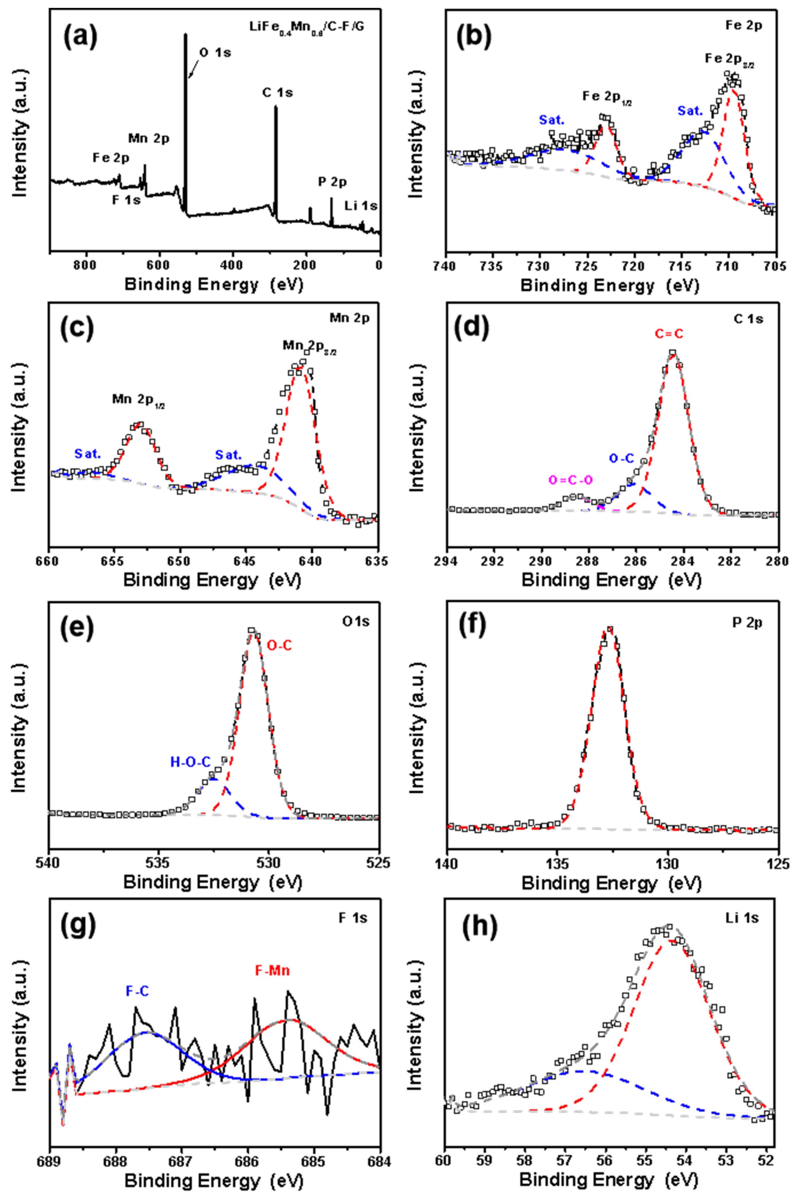
Scheme 1. Schematic illustration of the synthesis process.
Batteries 10 00272 sch001
Figure 1. XRD spectra of LMFP/C, LMFP/C/G, and LMFP/C-F/G.
Batteries 10 00272 g001
Figure 2. (ad) TEM image of LMFP/C-F/G and (h) HRTEM image of LMFP/C-F/G. The element mapping under (e) HAADF conditions showed that the (f) C, (g) O, (i) Fe, (j) Mn, (k) P, and (l) F elements were uniformly distributed on LMFP particles, indicating that LMFP/C-F/G was synthesized successfully.
Batteries 10 00272 g002
Figure 3. (a) XPS survey spectra of LMFP/C-F/G and the high-resolution spectrum of (b) Fe 2p; (c) Mn 2p; (d) C 1s; (e) O 1s; (f) P 2p; (g) F 1s; and (h) Li 1s.
Batteries 10 00272 g003
Figure 4. (a) CV curves at a scan rate of 1.0 mV s−1 and (b) electrochemical impedance spectroscopy patterns of LMFP/C, LMFP/C-F, and LMFP/C-F/G.
Batteries 10 00272 g004
Figure 5. Cyclic voltammetry curves of cathodes (a) LMFP/C-F/G, (b) LMFP/C/G, and (c) LMFP/C at various scanning rates. Linear fitting of Ip vs. v1/2 for cathodes LMFP/C-F/G ((a’,a’’)), LMFP/C/G ((b’,b’’)), and LMFP/C ((c’,c’’)) at corresponding Mn and Fe redox peaks.
Batteries 10 00272 g005
Figure 6. Electrochemical performance of LMFP/C-F/G at 25 °C: (a) first three charge/discharge curves at 0.1 C; (b) rate performance at different C rates, and (c) corresponding charge/discharge curves. (d) Cycling performance with corresponding Coulomb efficiency.
Batteries 10 00272 g006
Figure 7. Electrochemical performance of three samples at 25 °C: (a) first charge/discharge profiles at 0.1 C; (b) rate performance at different C rates.
Batteries 10 00272 g007
Table 1. Elemental composition (at %) measured by XPS.
SampleCOFLiFeMnPFe:Mn
LMFP/C29.5525.83--33.921.532.426.754:6
LMFP/C/G49.2522.00--50.881.021.604.194:6
LMFP/C-F/G39.3822.400.2829.331.281.945.384:6
Table 2. Redox potential difference in CV curves for three samples.
SampleFe3+Fe2+Mn3+Mn2+EFeEMn
LMFP/C3.763.314.413.850.450.56
LMFP/C/G3.663.394.263.860.270.40
LMFP/C-F/G3.673.424.233.870.250.36
Disclaimer/Publisher’s Note: The statements, opinions and data contained in all publications are solely those of the individual author(s) and contributor(s) and not of MDPI and/or the editor(s). MDPI and/or the editor(s) disclaim responsibility for any injury to people or property resulting from any ideas, methods, instructions or products referred to in the content.

