Article

Addition of a Polar, Porous Phase-Inversion-PVDF Membrane to Lithium–Sulfur Cells (LSBs) Already with a Microporous Polypropylene Separator Enhances the Battery Performance

School of Chemistry and Chemical Engineering, University of Surrey, Guildford GU2 7XH, UK
*
Author to whom correspondence should be addressed.
Batteries 2024, 10(8), 293; https://doi.org/10.3390/batteries10080293
Submission received: 12 July 2024 / Revised: 6 August 2024 / Accepted: 16 August 2024 / Published: 21 August 2024
(This article belongs to the Special Issue Energy-Dense Lithium-Sulfur Batteries)

Abstract

:
Lithium–sulfur batteries (LSBs) are widely studied as an alternative to lithium-ion batteries, this emphasis being due to their high theoretical energy density and low cost, and to the high natural abundance of sulfur. Lithium polysulfide shuttling and lithium dendrite growth have limited their commercialization. Porous polyvinylidene fluoride (PVDF) separators have shown improved performance (relative to hydrocarbon separators) in lithium-ion batteries due to faster lithium-ion migration and higher Li+ transference number. A thin polar PVDF membrane has now been fabricated via phase inversion (an immersion-precipitation method) yielding a β (polar) phase concentration of 72%. Preparation from commercial PVDF used dimethylformamide (DMF) solvent at the optimized crystallizing temperature of 70 °C, and pores in the membrane were generated by exchange of DMF with deionized water as non-solvent. The polar PVDF film produced has the advantages of being ultrathin (15 µm), lightweight (1.15 mg cm−2), of high porosity (75%) and high wettability (84%), and it shows enhanced thermal stability relative to polypropylene (PP). The porous, polar PVDF membrane was combined with a commercially available PP membrane to give a hybrid, two-layer, separator combination for LSBs. A synergy was created in the two-layer separator, providing high sulfur utilization and curbing polysulfide shuttling. The electrochemical performance with the hybrid separator (PP–β-PVDF) was evaluated in LSB cells and showed good cyclability and rate capability: those LSB cells showed a stable capacity of 750 mA h g−1 after 100 cycles at 0.1 C, much higher than that for otherwise-identical cells using a commercial PP-only separator (480 mA h g−1).

1. Introduction

The rapid developments in portable electronic devices, electric vehicles, and smart grids are driving the need for high-energy density (>500 W h kg−1) secondary (i.e., rechargeable) batteries. Although the performance of lithium-ion batteries (LIBs) continues to improve [1], they are approaching their theoretical specific energy (~387 W h kg−1 when using a LiCoO2 cathode). Further, some issues such as the high cost of lithium and the limited availability of Li, Co, and Ni have led to a search for alternative battery chemistries. Research into alternative technologies (i.e., beyond Li-ion batteries) reflects an ever-increasing need for efficient energy storage systems for portable electronic equipment, electric vehicles, and large-scale smart grids, and includes targets such as sodium-ion batteries (NIBs) [2], magnesium-ion batteries [3], calcium-ion batteries [4], aluminum-ion batteries [5], fluoride-ion batteries [6], and other approaches. Lithium–sulfur batteries (LSBs) are believed to be close to commercialization and have high theoretical energy density (2600 W h kg−1 or 2800 W h dm−3) [7]. S is a multivalent nonmetal that can interact with Li by an overall two-electron (per S atom) reaction:
S 8 + 16 e + 16   L i + 8 L i 2 S
The associated chemistry offers a theoretical capacity of ca. 1675 mA h g−1 (per unit mass of sulfur) [7], significantly higher than the ~140–300 mA h g−1 offered by intercalation-type cathode materials in LIBs [8].
The charge–discharge process for LSBs is in fact a complex, multistep process with polysulfide chain intermediates (Li2Sx, 3 ≤ x ≤ 8).
1st voltage plateau3 S8 + 6 Li+ + 6 e ↔ 3 Li2S8
sulfur utilization3 Li2S8 +2 Li+ + 2 e ↔ 4 Li2S6
4 Li2S6 + 4 Li++ 4 e ↔ 6 Li2S4
2nd voltage plateau6 Li2S4 + 12 Li+ + 12 e ↔ 12 Li2S2
polysulfide conversion12 Li2S2 + 24 Li+ + 24 e ↔ 24 Li2S
In contrast to the case for Li2S2 and the final product Li2S, the chain intermediates are highly soluble in the currently available ether-based electrolytes for LSB use. The discharge process therefore produces dissolved (in the electrolyte) polysulfide ions that can shuttle through the permeable separator into the anode compartment, thereby lowering sulfur utilization and charge storage capacity.
LSBs present several challenges that have hindered their widespread adoption as a primary energy storage solution: coulombic efficiency due to low active material (sulfur) utilization, poor cycling stability due to the formation of a solid electrolyte interphase (SEI) on the sulfur cathode, capacity fading, and lithium-dendrite formation [9,10,11]. Further, sulfur has low solubility in lithium-ion electrolytes, which can lead to the precipitation of lithium polysulfides (LiPSs) in the electrolyte. This can reduce the capacity of the battery and result in loss of performance over time. Despite these challenges, significant progress has been made in the development of LSBs in recent years.
Strategies that have been proposed for improving the performance of LSB cells have included modifying the sulfur cathode [12,13], redesigning the electrolyte [14,15], stabilizing the lithium anode [16,17], and improving the separator [18,19]. One recent development claims very high capacity (>1200 mA h g−1) and durable performance for an LSB with a garnet-type electrode and a polymer gel electrolyte [20]. Engineering advanced separators at the atomic up to meso scale is an approach to mitigation of the shuttling issue. Using separators with improved permeability and selectivity for Li+ ions can reduce the formation of the SEI and improve the cycling stability of LSBs. There are several ways to seek to improve the separator for LSBs relative to use of commercial microporous separators (principally polypropylene, PP): incorporating ceramic materials [21], developing multi-layer separators [22,23], and nanofiber separators [24] can improve the stability and performance of Li-S batteries by changing ion permeability and preventing dendrite formation. Diffusion of polysulfides (shuttling) across the porous separator can be partially curbed by introducing functional groups as coating layers on the cathode side of separators or by employing a solid electrolyte membrane to completely block the permeation of LiPSs [25,26,27].
Asymmetrical “Janus” and hybrid-type separators have been proposed and tested for their applicability in Li-S batteries. For instance, a polypropylene/mesoporous cellular graphene framework membrane has been used as a Janus separator to promote the utilization of sulfur cathode [28], yielding a high initial capacity of 1109 mA h g−1 and a persistent capacity of 800 mA h g−1 after 250 cycles at 0.2 C. A hybrid separator composed of glassy fiber paper and a microporous membrane was designed with a view to high-performance LSBs [29]: that separator successfully restrained the polysulfide shuttle process. Song et al. designed a hybrid separator made by grafting of poly(acrylic acid) (PAA) on the surface of polypropylene (PP) separator to enhance the performance of LSBs [26]: the LSB cell with that separator showed enhanced cycling stability with a very low capacity decay of 0.074% per cycle over the first 600 cycles at 0.5 C.
In comparison with polyolefin separators, polyvinylidene fluoride (PVDF) and its copolymers show excellent performance for their use as separator membranes in lithium-ion batteries due to the high dipole moment of the C–F bond and the associated high dielectric constant of the material [30]. This area has been extensively reviewed, e.g., [31]. Continuous porous membranes and nanofibrous PVDF-containing materials produced by standard syringe techniques (e.g., [32]) are non-polar due to neighboring C–F bond dipole pairs being in opposite directions (as in the α phase of PVDF). These polymers show excellent thermal and mechanical properties, good wettability in organic solvents, and are chemically inert and stable in the cathodic environment. More importantly, their porosity can be easily varied according to requirement. Among the various forms of PVDF, the β phase displays the largest membrane polarity due to the parallel alignment of neighboring atomic-level, bond dipole (C–F bond) pairs along the entire PVDF polymer chain [33]. This results in a bulk phase that is itself polar, with directional ordering at the molecular level due to the electric field during electrospinning. The F atoms are the negative end of each atomic-level dipole and are on the exterior of the chain, whereas the carbon atoms that are the positive ends are buried centrally within the chain. Polar PVDFs are therefore candidate non-ionic materials for selective mitigation of polysulfide shuttling by electric field repulsion of long-chain, negatively charged, polysulfide ions by the PVDF chain surfaces of the pore structure. Further, ordered polarity (achievable with controlled phase composition) can create a near-uniform lithium diffusion environment/electric field that may also reduce the dendrite formation and corrosion at the anode [33].
In this study, an engineered, hybrid separator (using two adjacent but separate membrane films) for high-performance Li-S batteries is fabricated and tested. The approach introduces a low-cost polar PVDF membrane in addition to a PP (Celgard 2400) membrane. Polar PVDF has already been employed in lithium-ion batteries to significantly and disruptively improve the electrochemical performance and migration of Li+ ion by its intrinsically selective associated electric field [30]. The polar PVDF (predominantly β phase) membrane in the current study has been synthesized by a simple two-step process using a phase inversion method. The β-phase concentration of the membrane was determined by Raman and FTIR absorption spectroscopies. Contact angle analysis and n-butanol tests were performed to examine the wettability and porosity of the membrane, respectively. In constructing test cells, the PP membrane was placed at the anode side and the β-PVDF membrane at the cathode side, the latter to avoid the direct contact of polysulfides with the active, metallic lithium, anode surface (where they would otherwise react, leading to anode corrosion). β-PVDF, with its internal and external surface charge, is present to repel negatively charged polysulfide ions, which then remain in the cathode compartment, where they can continue to be utilized in cathodic electrochemistry.
The electrochemical properties of cells with and without the addition of the PVDF membrane were determined by cyclic voltammetry and by galvanostatic discharge–charge (GDC) measurements. All test cells included a commercially available sulfur cathode. The inclusion of the PVDF membrane (the hybrid PP–β-PVDF approach) led to enhanced cell performance (high capacity, high coulombic efficiency, improved capacity retention, and good rate capability) relative to otherwise-identical cells made using a PP-only separator approach.
The investigators chose deliberately to maintain constant all cell assembly variables other than the separator used. For that reason, a standard commercial cathode was chosen and was found to lead to capacity values repeatable within 5% regardless of the commercial batch used. This enabled meaningful and direct identification of the effect of variation of the separator and reliable testing of the research hypothesis of polysulfide shuttle inhibition. The effects seen cannot be assigned to the chosen electrolyte composition or to any changed diffusion path within the identical cathodes.

2. Experimental

2.1. Materials

All chemicals were used after drying, but without any further treatment. Polyvinylidene fluoride (PVDF, 534,000 g mol−1), dimethylformamide (DMF), and n-butanol were purchased from Sigma Aldrich. 1,3-Dioxolane (DOL, 99.5%), 1,2-Dimethoxyethane (DME. 99.5%), LiNO3 (99.9%), lithium bis(trifluoromethane)sulfonimide (LiTFSI. 99.95%), Li2S, l, Li foil (99.9%, 0.75 mm thick) and sublimed sulfur powder were acquired from Alfa Aesar. PP (Celgard 2400) separator and Nanomyte BE-70E (sublimed sulfur on carbon, sulfur loading 3.26 mg cm−2) electrode sheet (a commercial cathode with a commercially relevant sulfur loading) were received from Pi-Kem and NEI corporation, respectively. Prior to making the electrolyte solution, LiTFSI was dried on a Schlenk line for three days at 120 °C under dynamic vacuum.

2.2. PVDF Membrane Fabrication by Phase Inversion

Polar PVDF films were prepared following a method in the literature [30,31]. Commercial PVDF was dissolved in DMF as solvent (to give 10% mass PVDF), stirring the solution at 30 °C until it became clear (ca. 3 h). A coagulation bath was prepared by adding 1.5 dm3 of deionized water to a 2 dm3 crystallizing dish and heating that to 70 °C. The clear PVDF solution was cast on a glass plate using a doctor blade (casting thickness 1 mm). Immediately after casting the solution onto the glass substrate plate, the assembled layer + glass was immersed in the coagulation bath for 1 h. Finally, the product film was peeled from the plate and air-dried at room temperature for ≥24 h.
Attempting to deposit phase-inverted β-PVDF directly onto a Celgard film would not lead to a functioning battery separator. The PP separator is porous, and deposition by phase-inversion onto/into porous PP would result in blocking of the PP pores, so preventing ion transport. In contrast, in this study, a PVDF solution lays on a non-porous surface prior to the washing with the non-solvent (water) that yields porous, polar β-PVDF film PVDF to use in combination with a porous PP film.

2.3. Film Characterization

Raman spectra for the PVDF-only membrane were recorded using a Thermo Scientific DXR3 Raman microscope at 6 mW power (780 nm laser). Each spectrum is the average of 10 separate measurements, following baseline correction using Spectragryph software (version 1.2.16). Each spectral average was referenced to the most intense peak (that at 497 cm−1). Fourier-transform infrared (FTIR) spectroscopy was performed with a Perkin Elmer Spectrum Two Fourier Transform (FT) spectrometer with a universal attenuated total reflectance (UATR) ZnSe/diamond accessory. The analysis constituted 32 scans in the range 4000–400 cm−1, with a 2 cm−1 resolution. The morphologies of films were studied using scanning electron microscopy (SEM) (Apreo SEM (FEG/SEM) (Thermo Scientific, Altrincham, UK)) and the wetting of films was investigated using an optical contact angle measuring and contour analysis system (Krüss DCA25B).
The β-phase content of each membrane was calculated from the FTIR spectra via the following equation [31]:
  F β / % = A β K β K α A α + A β × 100
where F(β) denotes the β-phase content. Aα and Aβ are the absorbances of the α and β phase of the membrane at the frequencies 766 and 840 cm−1, respectively. Kα and Kβ are the absorption coefficients at the respective frequencies. The value of Kα is 6.1 × 104 cm2 mol−1 and Kβ is 7.7 × 104 cm2 mol−1 [32].

2.4. Membrane Porosity and Electrolyte Uptake

The porosity of membranes was quantified after soaking in n-butanol for 2 h and gently wiping off (with paper tissue) residual liquid at the surface. The porosity P was calculated according to the following equation [33]:
P / % = M w e t ρ b M w e t ρ b + V s × 100
where Mwet is mass of the soaked membrane, VS is volume of the dry membrane, and ρb is density of n-butanol (0.81 g cm−3).
In gravimetric determination of electrolyte uptake, initially dry membranes were first immersed in the LSB electrolyte (see below) for various time durations, then removed and excess electrolyte dabbed off the surface. The film was weighed before and after absorbing the electrolyte. The electrolyte uptake as a function of time was determined using the following equation [34]:
u p t a k e t / % = ( M w e t ( t ) M d r y ) M d r y ( t ) × 100
where t is the time duration (5, 10, 15, and 30 min) of immersion of the membrane in the electrolyte, Mwet(t) is the total mass of the film + electrolyte, and Mdry is the mass of the dry film.

2.5. Electrodes and Electrochemical Characterization

Nanomyte sulfur-electrode foil was used as cathode and Li foil was used as anode, and either PP–β-PVDF or PP served as separator. LiTFSI (1 mol dm−3) plus LiNO3 (0.8 mol dm−3) in mixed solvents DME and DOL (1:1 by volume) was used as the electrolyte solution for Li-S (LSB) cells. In 2-electrode CV studies, voltages are given relative to Li/Li+.
Coin cells (CR2032, 304 stainless steel, wave spring, 2 steel separator disks) were crimped in an Ar-filled dry box (MBRAUN Unilab, <0.1 ppm of both O2 and H2O). All assembled cells were rested for at least 3 h before electrochemical cycling. The electrolyte-volume to sulfur-mass (E/S) ratio was kept constant at 12 in assembling all cells, as lower E/S values did not lead reliably to adequately wetted electrodes with the PP–β-PVDF hybrid separator assembly. Additional electrolyte relative to the PP-only case is necessary to pore-fill the polar PVDF film.
The galvanostatic discharge–charge (GDC) cycling behavior of Li-S cells was investigated using Gamry Reference 600 potentiostats in the voltage range of 1.8–2.8 V. Two-electrode cyclic voltammetry (CV) experiments used a scan rate of 0.2 mV s−1 between 1.5 and 3.0 V (versus Li/Li+). For investigations of possible pseudocapacitance, CV traces were also determined at scan rates in the range of 0.1 to 0.5 mV s−1. Equations (4) and (5) show the relationship between current (i) and scan rate (ν), and are used in determining the value of the variable b [35]:
i = a ν b
log i = b log ν + log a
where a and b are variable parameters and ν is scan rate (mV s−1). In establishing repeatability, three cells were studied for each LSB type (3 cells with PP-only separator and 3 cells with hybrid separator). The results below refer to a single cell in each case. Voltage plateaus were similar within each type, and charge storage capacities were repeatable within a range of ±5%. Within that range and for cells with the hybrid separator approach, no influence of orientation of the polar PVDF separator (“glass” side toward neighboring PP membrane or towards cathode) was detected or of deliberate use of Nanomyte electrodes from 2 different commercial batches.

3. Results and Discussion

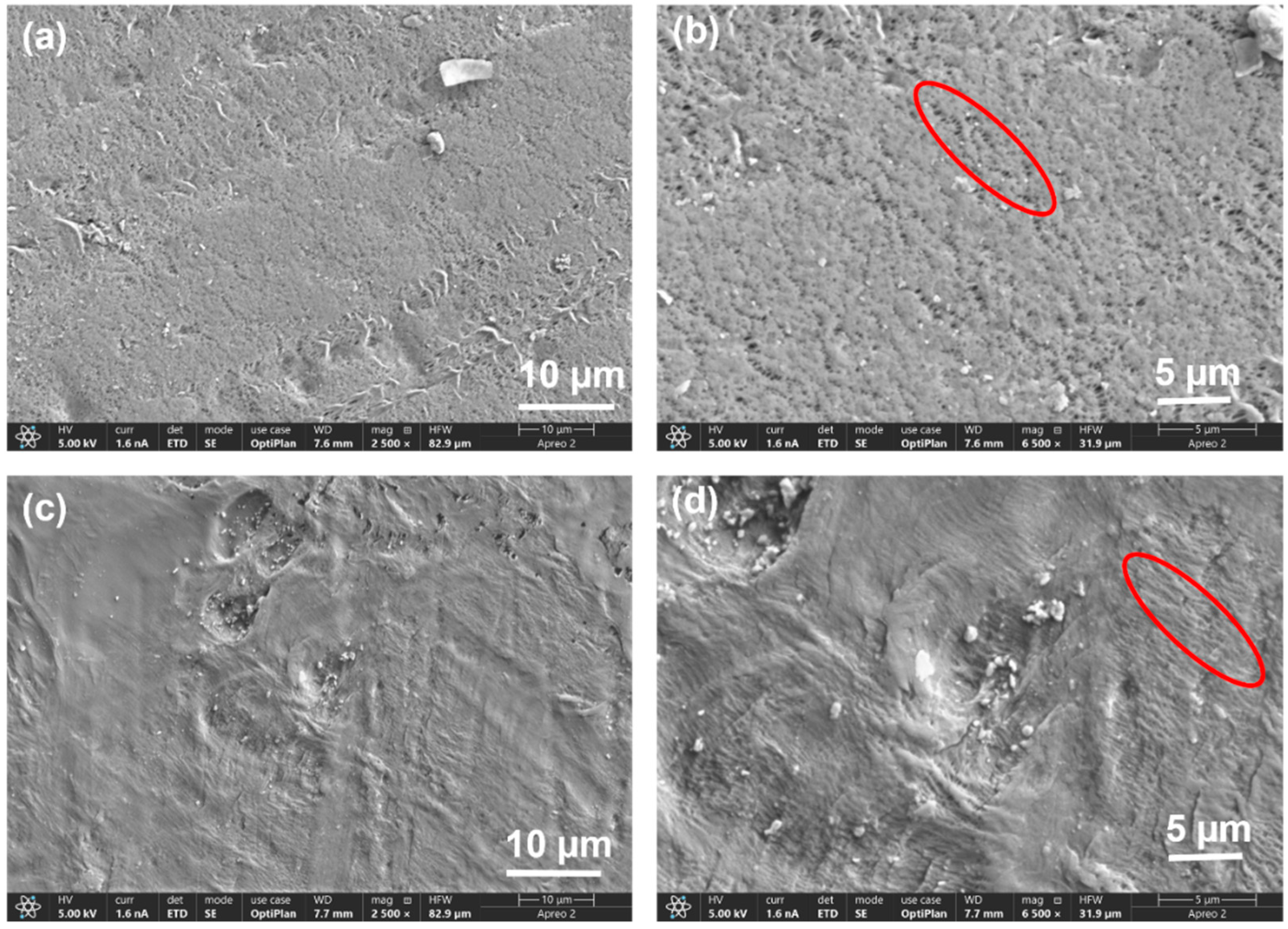
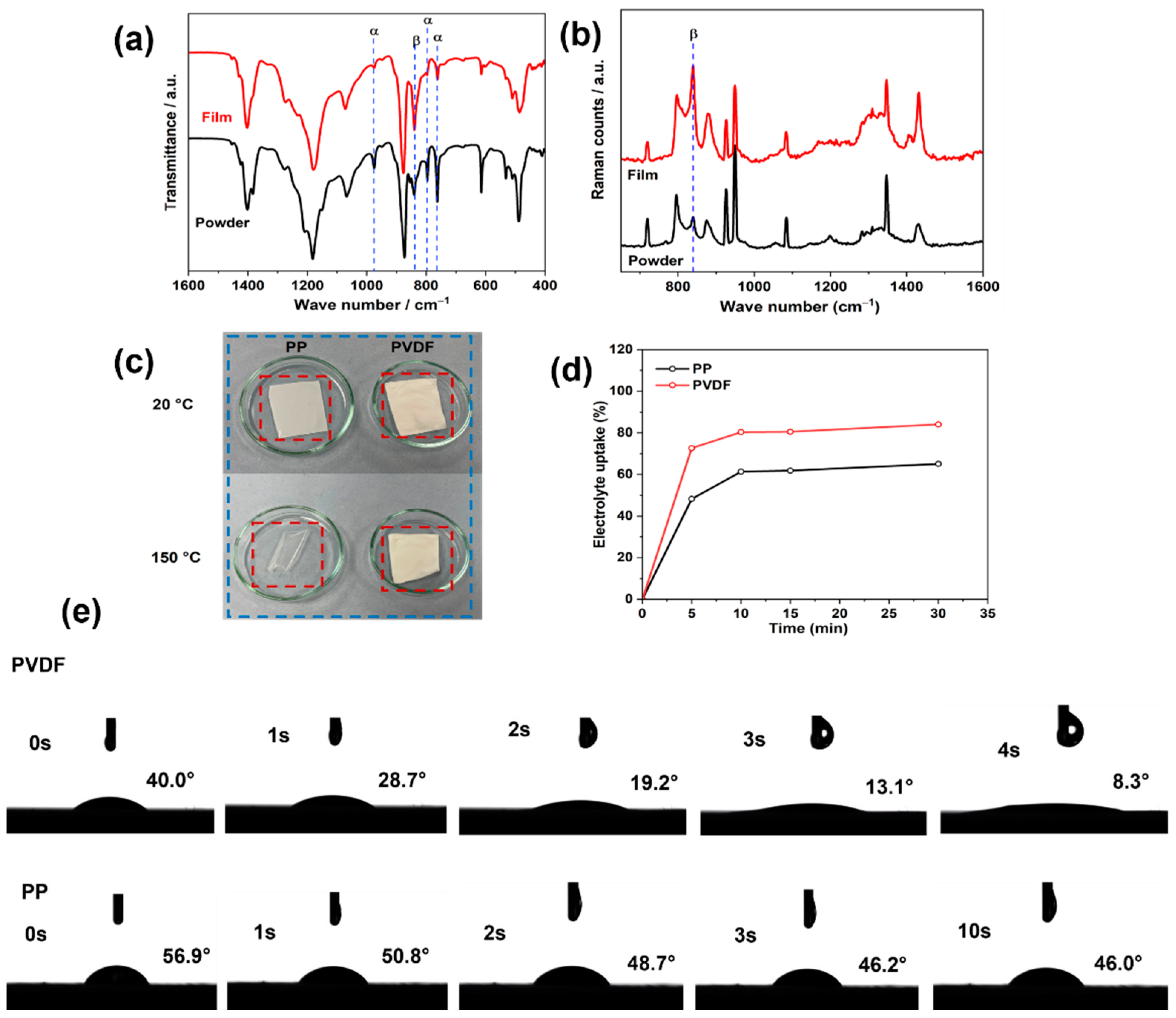
3.1. Characterization of the PVDF Membrane

Porous PVDF films with high content of the polar β phase and with asymmetric, porous morphology were produced by the phase inversion method [31]. The microstructures (surface views) of the as-prepared β-PVDF membrane and of commercial PP membranes are presented in Figure 1a–d. β-PVDF membranes/films have a sponge-like porous microstructure with micron-sized interconnected pores. Those pores are homogeneously distributed across the surface of the membrane. The porous structure of the films is explained by the ternary-system phase diagram for the polymer, solvent, and nonsolvent. The phase diagram is controlled, according to the Flory–Huggins theory [36,37], by the interaction parameters of the polymer–solvent, polymer–nonsolvent and nonsolvent–solvent for ternary systems, and a phase separation occurs during the solvent–nonsolvent exchange process.
As discussed in the introduction, separator films are porous at the micro and meso levels. SEM will then detect evidence only of the largest pores. Comparing the SEM images of the two membrane types, the as-prepared β-PVDF membrane had more pores with large diameter than the PP membrane. Those pores are clearly visible (e.g., within the red ring in Figure 1b) for the PVDF membrane, whereas in the PP membrane the pores are not visible, even at the higher magnification (e.g., within the red ring in Figure 1d).
The FTIR spectra of both β-PVDF membrane and the parent, commercial PVDF powder are shown in Figure 2a,b. The vibration bands at 765, 796, and 976 cm−1 are characteristic of the α phase of the PVDF, whereas the vibration band at 840 cm−1 is attributed to/due to the β phase [32]. Assignments are in agreement with literature values [30]. For the spectrum of PVDF powder, the peak due to the β phase is much lower in intensity than those for the α phase, demonstrating the presence of low β-phase content (Figure 2a, bottom spectrum). In contrast, in spectra for the polar membrane, the peak intensity corresponding to the β phase is much higher, indicating α-to-β phase transformation during the phase inversion process. The β-phase content calculated using Equation (1) is 72%. Raman spectra (Figure 2b) also show higher content of β phase (an elevated intensity at 840 cm−1) fabricated, β-rich porous membrane than for the parent powder, in agreement with the FTIR data.
Thermal stabilities of the films were investigated via heating experiments, as shown in Figure 2c. The PP membrane shrank and become transparent (losing its pores) after heating at 150 °C. In contrast, the shape and pores of the β-PVDF membrane were essentially unchanged at 150 °C, PVDF having a melting temperature of 177 °C [38].
Porosities for the membranes were evaluated using the n-butanol test and Equation (2). The β-PVDF membrane possessed higher porosity (75%) relative to the PP membrane (57%).
Figure 2d shows the evolution of electrolyte uptake with time for the differing membranes, electrolyte uptakes being calculated using Equation (3). Membranes had swollen visibly on immersion in electrolyte. An uptake of 72% was found for β-PVDF membrane after soaking in electrolyte for 5 min and this value increased to 84% after 30 min, this behavior indicating good electrolyte uptake. The commercial PP separator membrane (Celgard 2400) had an initial (5 min) electrolyte uptake of 48% which increased to 65% after 30 min, both values being lower than for the β-PVDF membrane, reflecting lower porosity in the PP case. Wettability as a function of time was followed via time-dependent contact-angle measurements. As shown in Figure 2e, the electrolyte contact angle for the PP separator was 56.9° at 0 s and 46.0° after 30 s, whereas that for β-PVDF film was 40° at 0 s and decreased to 8° after only 4 s, the electrolyte being absorbed very rapidly by the β-PVDF film.

3.2. Visual Studies of Polysulfide Permeation through Separator Membranes

In checking the hypothesis of inhibition of polysulfide shuttling, a visual Li2S6-permeation test was carried out). A literature report indicates that increasing the number of sheets of PP-only separator membrane in a LSB can be effective in reducing polysulfide shuttling between LSB electrodes [39]. In a study using electrospun nanofiber-polar PVDF, the authors of the current article found polysulfide shuttling to be substantially hindered by that membrane on its own [40]. In contrast, in the current study, that was found not to be the case for β-PVDF film produced by the phase inversion method, and so the hybrid (PP–β-PVDF) was developed.
Li2S and S powder were added to 1,2-dimethoxyethane (DME) solvent and the solution was homogenized by vigorous stirring in a closed vessel inside an Ar-filled dry box (MBRAUN Unilab) (Unilab by M. Braun Inertgas-systema GMBH, Garching, Germany). To explore the effect of PP and polar PVDF separators on polysulfide permeation, a visual experiment was carried out in the dry box with an H-type cell containing the highly colored Li2S6 solution (5 mmol dm−3) and pure DME (colorless) contacted across the separator.
A merit of β-PVDF, for application in a separator in LSBs is its ability to hinder the migration of polysulfide from the sulfur cathode to the Li anode. This is revealed by the visual polysulfide permeation test shown in Figure 3. For the PP separator (Figure 2, top row), the Li2S6 gradually diffused through the separator, and the crossover became more and more evident as time increased. For the hybrid, PP–β-PVDF, the separator exhibited much less and much slower crossover (color), as evident from the DME coloration.
The hybrid two-membrane approach (a PP membrane plus a β-PVDF membrane) led to substantially reduced cross-membrane diffusion of Li2S6 compared to use of a PP membrane, demonstrating effective hindrance of polysulfide shuttling across the hybrid (two-sheet) separator. These variations in behavior merit discussion. The electrospun polar PVDF membrane was 35 μm thick, with complex tortuosity in three dimensions. The interior of that membrane acts as a reservoir for inhibition of polysulfide crossover and is itself enclosed by permeating, negatively charged pore walls [40]. In contrast, the porosity in the thinner (15 μm) β-PVDF from phase inversion is oriented through the membrane, and the additional PP membrane in the hybrid approach acts as a reservoir to maintain wetting of that PVDF.

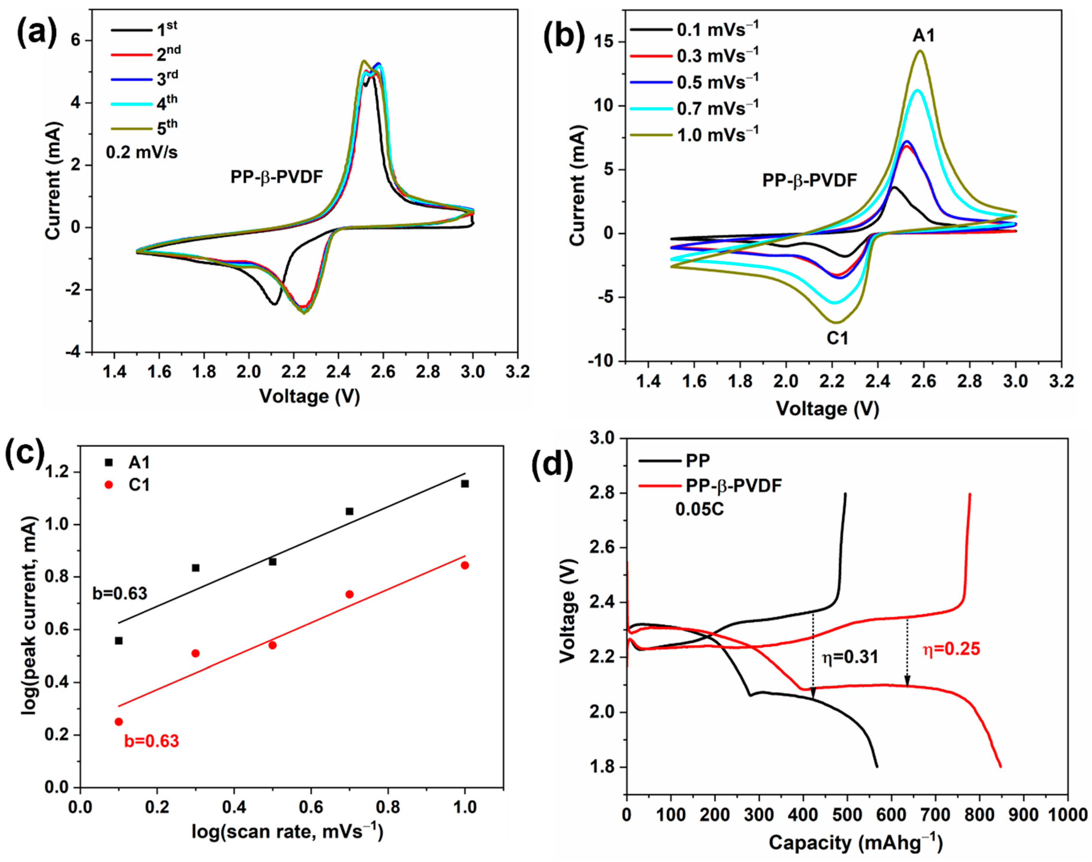
3.3. CV Traces and the First GDC Cycle

Cyclic voltammetry (CV) traces for the Li-S cells assembled with PP–β-PVDF separators are presented in Figure 4a. The CV scans were performed at a scan rate of 0.2 mV s−1 between 1.5 and 3.0 V (two-electrode versus Li/Li+). In the positive scan, one minor peak at 1.95 V and one major peak at 2.25 V can be discerned: the minor peak (1.95 V) is due to the reduction of S8 to soluble Li2Sx (3 ≤ x ≤ 8), and the major peak (2.25 V) is due to the further reduction of Li2Sx to solid Li2S2/Li2S [40]. In the reverse scan, two clear peaks were observed at 2.52 and 2.58 V: the former peak relates to the oxidation of Li2S2/Li2S to Li2Sx, while the latter peak corresponds to the further oxidation of Li2Sx to elemental S8 [41].
CV traces as a function of scan rate were also recorded (see Figure 4b) for cells with the PP–β-PVDF separator, using Equations (4) and (5) to probe pseudocapacitive response via the coefficient b. As evident in Figure 4c, the experimental b values (slope) of each linearized fit (separate fits for cathodic and anodic peak currents) were identical, with b = 0.63. This b value shows that the storage capacity of LSB cells with the PP–β-PVDF separator is indeed diffusion-controlled, confirming the battery-like process.
The initial galvanostatic, GDC, curves of batteries assembled with PP–β-PVDF and PP separators at 0.05 C are compared in Figure 4d. Notably, the cell with PP–β-PVDF separator exhibits a lower overvoltage gap than that of the PP separator (η = 0.22 V compared to η = 0.31 V), indicating that the hybrid separator reduces polarization and provides better stability and reversibility for Li–S batteries (LSBs) [42].

3.4. Detailed Electrochemical Cycling Studies of LSBs with the Hybrid Separator Combination and with PP Only

Figure 5a,b depicts successive charge–discharge profiles for Li-S (LSB) cells using PP–β-PVDF and PP separators at 0.05 C. The discharge curves have two plateau voltages, at 2.1 and 2.3 V, consistent with the CV traces (Figure 4a). The first discharge capacity amounts to 847 mA h g−1, which is around half of the theoretical values with sulfur (1675 mA h g−1), indicating incomplete reaction at the electrode. The first charge capacity was lower, at 777 mA h g−1, meaning only 92% of the discharge capacity was reversible. The irreversible component may be linked due to the formation of a SEI as in the case of LIBs [43]. In later cycles, the capacity increases and the voltage gap between the plateaus decreases, in agreement with the CV traces. The increase in capacity in early cycles demonstrates an activation process.
With the PP-only separator, the first charge capacity is 566 mA h g−1, which is 281 mA h g−1 lower than with the PP–β-PVDF separator. An activation process is evident in higher capacities obtained in later cycles, but the capacities remain substantially lower than with the two-membrane approach. Cells with the PP–β-PVDF separator deliver a high fourth-cycle capacity, as shown in Figure 4b (937 mA h g−1), consisting of a short and high plateau (QH = 288 mA h g−1) and a later long and low plateau (QL = 650 mA h g−1). The corresponding figures with the PP-only separator are much lower (QH = 275 mA h g−1, QL = 360 mA h g−1). Use of the hybrid (two-membrane) separator led to continued utilization of a higher percentage of the sulfur present in the virgin cathode, indicating effective suppression of the polysulfide shuttle effect.
Figure 5c demonstrates the cycling charge capacities at a higher current, 0.1 C. The values are always significantly higher when the PP–β-PVDF separator approach is used. For the PP–β-PVDF case, the first cycle discharge capacity is 630 mA h g−1, increasing progressively to 762 mA h g−1 after 60 cycles and becoming stable. A capacity of 725 mA h g−1 was obtained after 100 cycles, indicating 86% capacity retention. The black curve corresponds to the PP separator, for which the discharge capacity increases from an initial 342 to 514 mA h g−1 in the 64th cycle, after which the capacity fades progressively to 470 mA h g−1 after 100 cycles.
The rate capabilities of LSB cells with the hybrid (two-membrane) separator were examined by power cycling at currents corresponding to 0.05, 0.1, 0.2, 0.5, 1, and 2 C and finally back to 0.05 C: the results are shown in Figure 5d. Specific capacities of 848, 632, 482, 365, 273, 107, 765 mA h g−1 were obtained. Comparing the first and last values, there is a capacity retention of 90% after the power cycling sequence, thus demonstrating a good rate capability. The cells remain reasonably stable over a power cycling sequence.
The much-improved electrochemical performance of the LSB cell configured with the hybrid separator combination can be attributed to two main factors: (1) the high selectivity of the β-PVDF membrane, and (2) increasing the number of membranes being used. The former offers high active material utilization by providing a large amount of electrolyte to the cathode compared to the PP-only separator (with its lower wettability and porosity).

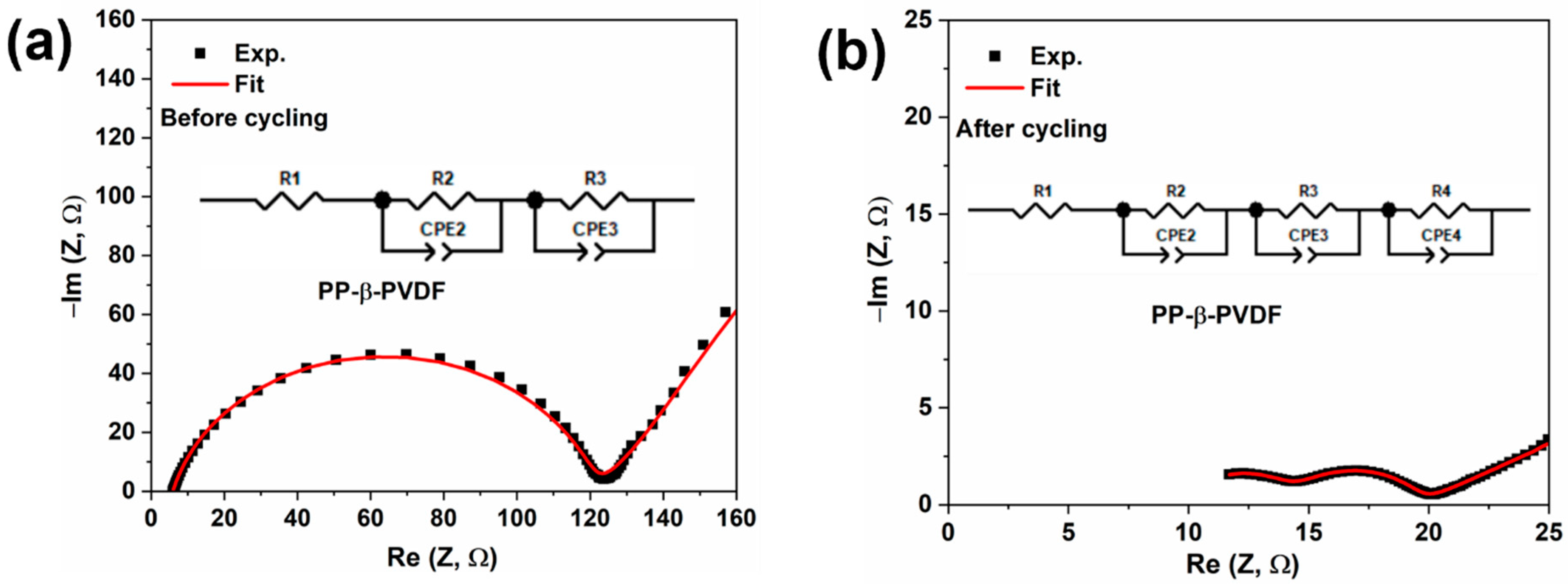
3.5. EIS Investigation of Cells before and after 100 Cycles

EIS measurements were carried out before and after cycling. Figure 6a,b show the Nyquist plots for cells fabricated using the hybrid separator approach. Equivalent circuits used in modeling impedance spectra are depicted in the insets.
Before cycling (Figure 6a), the impedance spectra consist of one “semicircle” and a tilted straight line, at high and low frequencies, respectively. Assumption of a simple Warburg impedance (W0 or WS) to represent ion diffusion in the cathode did not lead to successful fitting at low frequencies. This parallels the findings in some other battery-related studies (e.g., [44,45]), and a CPE was therefore used to produce an infinite-length Warburg element [46]. The “semicircle” corresponds to the charge-transfer process, and the straight line is related to the lithium-ion diffusion process [47].
After cycling (Figure 5b), the impedance spectrum consists of two “semicircles”, at high frequency and medium frequency, attributed to interfacial and charge-transfer resistance, and a tilted straight line at low frequency corresponding to ionic diffusion within the active material/cathode [48]. It is worth noting that no additional semicircle corresponding to features of any Li2S2/Li2S formed at the anode was obtained.
Before cycling, the electrolyte resistance was 5.9 ohms, which increased slightly to 7.8 ohms after cycling. The presence of some dissolved polysulfide after cycling did not lower the electrolyte resistance. Charge-transfer resistance before cycling was 118 ohms and was related to native passivation of the electrode. After cycling, charge-transfer resistance decreased to 4.4 ohm. The substantial decrease in that resistance upon cycling reveals the increased electrochemical activity of the sulfur cathode after activation. After cycling, the cell shows an interphase (SEI) resistance of 7.9 ohms, which is very similar in magnitude to the electrolyte resistance and so demonstrates formation of a stable and Li+-ion-conductive SEI.

4. Conclusions

A hybrid separator comprised of separate PP and β-PVDF membranes (the latter at the cathode side) has been designed and demonstrated for Li-S batteries (LSBs). The β-PVDF membrane was prepared by a low-cost, phase inversion method. The polar membrane (β-PVDF) has permanent dipoles present, providing an electric field that interacts with the electrolyte ions, providing high electrolyte storage (up to 84%), and high porosity results in quick absorption of the electrolyte. With the hybrid separator, a synergy is created, which results in high utilization of active material, as well as curbing polysulfide shuttling between the electrodes. The electrochemical performances of otherwise-identical LSBs are significantly improved relative to cells using only a standard commercial polyolefin film (Celgard 2400) and exhibit high coulombic efficiency, with very stable GCD cycling and a high retention of charge storage capacity (90%) over 100 cycles. The high electrolyte storage capability of β-PVDF was evaluated by contact angle analysis and wettability tests: the membrane showed high electrolyte uptake (up to 84%), suggesting possible high mass transfer of electrolyte into the cathode, which facilitates fast Li+ diffusion within the cathode.
The hypothesis that an added thin polar PVDF film will strategically hinder the polysulfide shuttling effect has been verified through a variety of physicochemical characterizations and electrochemical studies of LSB cells.

Author Contributions

Conceptualization, C.C. and R.C.T.S.; methodology, I.M. and L.D.J.B.; investigation, I.M. and L.D.J.B.; writing—original draft preparation, I.M.; writing—review and editing, R.C.T.S. All authors have read and agreed to the published version of the manuscript.

Funding

The authors gratefully acknowledge the financial support for conducting this Li-S battery research under the Lithium-Sulfur Technology Accelerator (LiSTAR) program funded by the Faraday Institution (grant FIRG014).

Data Availability Statement

The data presented in this study are available on request from the corresponding author. The data are not publicly available due to contractual restrictions.

Conflicts of Interest

The authors declare that they have no known competing financial interests nor any personal relationships that could have appeared to influence the work reported in this article. The funders had no role in the design of the study; in the collection, analyses, or interpretation of data; in the writing of the manuscript; or in the decision to publish the results.

References

  1. Armand, M.; Tarascon, J.-M. Building Better Batteries. Nature 2008, 451, 652–657. [Google Scholar]
  2. Slater, M.D.; Kim, D.; Lee, E.; Johnson, C.S. Sodium-Ion Batteries. Adv. Funct. Mater. 2013, 23, 947–958. [Google Scholar]
  3. Aurbach, D.; Lu, Z.; Schechter, A.; Gofer, Y.; Gizbar, H.; Turgeman, R.; Cohen, Y.; Moshkovich, M.; Levi, E. Prototype Systems for Rechargeable Magnesium Batteries. Nature 2000, 407, 724–727. [Google Scholar]
  4. Ponrouch, A.; Frontera, C.; Bardé, F.; Palacín, M.R. Towards a Calcium-Based Rechargeable Battery. Nat. Mater. 2016, 15, 169–172. [Google Scholar]
  5. Jayaprakash, N.; Das, S.K.; Archer, L.A. The Rechargeable Aluminum-Ion Battery. Chem. Commun. 2011, 47, 12610–12612. [Google Scholar]
  6. Mohammad, I.; Witter, R.; Fichtner, M.; Anji Reddy, M. Room-Temperature, Rechargeable Solid-State Fluoride-Ion Batteries. ACS Appl. Energy Mater. 2018, 1, 4766–4775. [Google Scholar]
  7. Pang, Q.; Liang, X.; Kwok, C.Y.; Nazar, L.F. Advances in Lithium–Sulfur Batteries Based on Multifunctional Cathodes and Electrolytes. Nat. Energy 2016, 1, 16132. [Google Scholar]
  8. Tarascon, J.-M.; Armand, M. Issues and Challenges Facing Rechargeable Lithium Batteries. Nature 2001, 414, 359–367. [Google Scholar] [PubMed]
  9. Fu, C.; Guo, J. Challenges and Current Development of Sulfur Cathode in Lithium–Sulfur Battery. Curr. Opin. Chem. Eng. 2016, 13, 53–62. [Google Scholar]
  10. Kolosnitsyn, V.S.; Kuzmina, E.V.; Karaseva, E.V. On the Reasons for Low Sulphur Utilization in the Lithium–Sulphur Batteries. J. Power Sources 2015, 274, 203–210. [Google Scholar]
  11. Manthiram, A.; Fu, Y.; Su, Y.-S. Challenges and Prospects of Lithium–Sulfur Batteries. Acc. Chem. Res. 2013, 46, 1125–1134. [Google Scholar]
  12. Li, Y.; Shapter, J.G.; Cheng, H.; Xu, G.; Gao, G. Recent Progress in Sulfur Cathodes for Application to Lithium–Sulfur Batteries. Particuology 2021, 58, 1–15. [Google Scholar]
  13. Lee, J.; Choi, W. Surface Modification of Sulfur Cathodes with PEDOT:PSS Conducting Polymer in Lithium-Sulfur Batteries. J. Electrochem. Soc. 2015, 162, A935. [Google Scholar]
  14. Liu, Y.; Elias, Y.; Meng, J.; Aurbach, D.; Zou, R.; Xia, D.; Pang, Q. Electrolyte Solutions Design for Lithium-Sulfur Batteries. Joule 2021, 5, 2323–2364. [Google Scholar]
  15. Chen, W.; Lei, T.; Wu, C.; Deng, M.; Gong, C.; Hu, K.; Ma, Y.; Dai, L.; Lv, W.; He, W.; et al. Designing Safe Electrolyte Systems for a High-Stability Lithium–Sulfur Battery. Adv. Energy Mater. 2018, 8, 1702348. [Google Scholar]
  16. Xiong, X.; Yan, W.; You, C.; Zhu, Y.; Chen, Y.; Fu, L.; Zhang, Y.; Yu, N.; Wu, Y. Methods to Improve Lithium Metal Anode for Li-S Batteries. Front. Chem. 2019, 7, 827. [Google Scholar]
  17. Han, D.-D.; Liu, S.; Liu, Y.-T.; Zhang, Z.; Li, G.-R.; Gao, X.-P. Lithiophilic Gel Polymer Electrolyte to Stabilize the Lithium Anode for a Quasi-Solid-State Lithium–Sulfur Battery. J. Mater. Chem. A 2018, 6, 18627–18634. [Google Scholar]
  18. Li, J.; Xiao, Z.; Chen, A.; Zhang, W.; Zhu, D.; Jin, Y.; Mao, Q.; Wang, G.; He, J.; Xia, Y. Functionally Modified Polyolefin-Based Separators for Lithium-Sulfur Batteries: Progress and Prospects. Front. Energy Res. 2020, 8, 593640. [Google Scholar] [CrossRef]
  19. Pavlin, N.; Hribernik, S.; Kapun, G.; Talian, S.D.; Njel, C.; Dedryvère, R.; Dominko, R. The Role of Cellulose Based Separator in Lithium Sulfur Batteries. J. Electrochem. Soc. 2018, 166, A5237. [Google Scholar]
  20. Shi, S.; Takeuchi, S.; Alexander, G.V.; Hamann, T.; O’Neill, J.; Dura, J.A.; Wachsman, E.D. High Sulfur Loading and Capacity Retention in Bilayer Garnet Sulfurized-Polyacrylonitrile/Lithium-Metal Batteries with Gel Polymer Electrolytes. Adv. Energy Mater. 2023, 13, 2301656. [Google Scholar]
  21. Ding, B.; Wang, J.; Fan, Z.; Chen, S.; Lin, Q.; Lu, X.; Dou, H.; Kumar Nanjundan, A.; Yushin, G.; Zhang, X.; et al. Solid-State Lithium–Sulfur Batteries: Advances, Challenges and Perspectives. Mater. Today 2020, 40, 114–131. [Google Scholar]
  22. Wang, Q.; Wen, Z.; Jin, J.; Guo, J.; Huang, X.; Yang, J.; Chen, C. A Gel-Ceramic Multi-Layer Electrolyte for Long-Life Lithium Sulfur Batteries. Chem. Commun. 2016, 52, 1637–1640. [Google Scholar]
  23. Wang, M.; Emre, A.E.; Kim, J.-Y.; Huang, Y.; Liu, L.; Cecen, V.; Huang, Y.; Kotov, N.A. Multifactorial Engineering of Biomimetic Membranes for Batteries with Multiple High-Performance Parameters. Nat. Commun. 2022, 13, 278. [Google Scholar] [PubMed]
  24. Pei, H.; Yang, C.; Wu, Q.; Zhou, X.; Xie, X.; Hwang, B.; Ye, Y. Ion-Selective Aramid Nanofiber-Based Janus Separators Fabricated by a Dry-Wet Phase Inversion Approach for Lithium–Sulfur Batteries. J. Mater. Chem. A 2022, 10, 5317–5327. [Google Scholar]
  25. Li, Z.; Tang, L.; Liu, X.; Song, T.; Xu, Q.; Liu, H.; Wang, Y. A Polar TiO/MWCNT Coating on a Separator Significantly Suppress the Shuttle Effect in a Lithium-Sulfur Battery. Electrochim. Acta 2019, 310, 1–12. [Google Scholar]
  26. Song, S.; Shi, L.; Lu, S.; Pang, Y.; Wang, Y.; Zhu, M.; Ding, D.; Ding, S. A New Polysulfide Blocker—Poly(Acrylic Acid) Modified Separator for Improved Performance of Lithium-Sulfur Battery. J. Membr. Sci. 2018, 563, 277–283. [Google Scholar]
  27. Kim, D.H.; Lee, Y.-H.; Song, Y.B.; Kwak, H.; Lee, S.-Y.; Jung, Y.S. Thin and Flexible Solid Electrolyte Membranes with Ultrahigh Thermal Stability Derived from Solution-Processable Li Argyrodites for All-Solid-State Li-Ion Batteries. ACS Energy Lett. 2020, 5, 718–727. [Google Scholar]
  28. Peng, H.-J.; Wang, D.-W.; Huang, J.-Q.; Cheng, X.-B.; Yuan, Z.; Wei, F.; Zhang, Q. Janus Separator of Polypropylene-Supported Cellular Graphene Framework for Sulfur Cathodes with High Utilization in Lithium–Sulfur Batteries. Adv. Sci. 2016, 3, 1500268. [Google Scholar]
  29. Wang, L.; Liu, J.; Haller, S.; Wang, Y.; Xia, Y. A Scalable Hybrid Separator for a High Performance Lithium–Sulfur Battery. Chem. Commun. 2015, 51, 6996–6999. [Google Scholar]
  30. Kundu, M.; Costa, C.M.; Dias, J.; Maceiras, A.; Vilas, J.L.; Lanceros-Méndez, S. On the Relevance of the Polar β-Phase of Poly(vinylidene fluoride) for High Performance Lithium-Ion Battery Separators. J. Phys. Chem. C 2017, 121, 26216–26225. [Google Scholar]
  31. Ribeiro, C.; Costa, C.M.; Correia, D.M.; Nunes-Pereira, J.; Oliveira, J.; Martins, P.; Gonçalves, R.; Cardoso, V.F.; Lanceros-Méndez, S. Electroactive Poly(vinylidene fluoride)-Based Structures for Advanced Applications. Nat. Protoc. 2018, 13, 681–704. [Google Scholar]
  32. Martins, P.; Lopes, A.C.; Lanceros-Mendez, S. Electroactive Phases of Poly(vinylidene fluoride): Determination, Processing and Applications. Prog. Polym. Sci. 2014, 39, 683–706. [Google Scholar]
  33. Pai, J.-Y.; Hsieh, C.-T.; Lee, C.-H.; Wang, J.-A.; Ku, H.-Y.; Huang, C.-L.; Hardwick, L.J.; Hu, C.-C. Engineering of Electrospun Polyimide Separators for Electrical Double-Layer Capacitors and Lithium-Ion Cells. J. Power Sources 2021, 482, 229054. [Google Scholar]
  34. Zhang, F.; Ma, X.; Cao, C.; Li, J.; Zhu, Y. Poly(vinylidene fluoride)/SiO2 Composite Membranes Prepared by Electrospinning and Their Excellent Properties for Nonwoven Separators for Lithium-Ion Batteries. J. Power Sources 2014, 251, 423–431. [Google Scholar]
  35. Lindström, H.; Södergren, S.; Solbrand, A.; Rensmo, H.; Hjelm, J.; Hagfeldt, A.; Lindquist, S.-E. Li+ Ion Insertion in TiO2 (Anatase). 2. Voltammetry on Nanoporous Films. J. Phys. Chem. B 1997, 101, 7717–7722. [Google Scholar]
  36. Flory, P.J. Thermodynamics of High Polymer Solutions. J. Chem. Phys. 1941, 9, 660. [Google Scholar]
  37. Huggins, M.L. Solutions of Long Chain Compounds. J. Chem. Phys. 1941, 9, 440. [Google Scholar]
  38. Saxena, P.; Shukla, P. A comprehensive review on fundamental properties and applications of poly(vinylidene fluoride) (PVDF). Adv. Compos. Hybrid Mater. 2021, 4, 8–26. [Google Scholar]
  39. Liao, J.; Ye, Z. Nontrivial Effects of “Trivial” Parameters on the Performance of Lithium–Sulfur Batteries. Batteries 2018, 4, 22. [Google Scholar] [CrossRef]
  40. Mohammad, I.; Barter, L.D.J.; Stolojan, V.; Crean, C.; Slade, R.C.T. Electrospun polar-nanofiber PVDF separator for lithium–sulfur batteries with enhanced charge storage capacity and cycling durability. Energy Adv. 2024, 3, 626–635. [Google Scholar]
  41. Zhang, L.; Guo, J. Understanding the Reaction Mechanism of Lithium–Sulfur Batteries by In Situ/Operando X-ray Absorption Spectroscopy. Arab. J. Sci. Eng. 2019, 44, 6217–6229. [Google Scholar]
  42. Jin, Z.; Xie, K.; Hong, X.; Hu, Z.; Liu, X. Application of Lithiated Nafion Ionomer Film as Functional Separator for Lithium Sulfur Cells. J. Power Sources 2012, 218, 163–167. [Google Scholar]
  43. Michan, A.L.; Divitini, G.; Pell, A.J.; Leskes, M.; Ducati, C.; Grey, C.P. Solid Electrolyte Interphase Growth and Capacity Loss in Silicon Electrodes. J. Am. Chem. Soc. 2016, 138, 7918–7931. [Google Scholar] [PubMed]
  44. Ahn, W.; Kim, K.-B.; Jung, K.-N.; Shin, K.-H.; Jin, C.-S. Synthesis and Electrochemical Properties of a Sulfur-Multi Walled Carbon Nanotubes Composite as a Cathode Material for Lithium Sulfur Batteries. J. Power Sources 2012, 202, 394–399. [Google Scholar]
  45. Yuan, L.; Qiu, X.; Chen, L.; Zhu, W. New Insight into the Discharge Process of Sulfur Cathode by Electrochemical Impedance Spectroscopy. J. Power Sources 2009, 189, 127–132. [Google Scholar]
  46. Deng, Z.; Zhang, Z.; Lai, Y.; Liu, J.; Li, J.; Liu, Y. Electrochemical Impedance Spectroscopy Study of a Lithium/Sulfur Battery: Modeling and Analysis of Capacity Fading. J. Electrochem. Soc. 2013, 160, A553–A558. [Google Scholar]
  47. Cañas, N.A.; Hirose, K.; Pascucci, B.; Wagner, N.; Friedrich, K.A.; Hiesgen, R. Investigations of Lithium–Sulfur Batteries Using Electrochemical Impedance Spectroscopy. Electrochim. Acta 2013, 97, 42–51. [Google Scholar]
  48. Cheng, Q. Porous Graphene Sponge Additives for Lithium Ion Batteries with Excellent Rate Capability. Sci. Rep. 2017, 7, 925. [Google Scholar]
Figure 1. SEM images of the surface of β-PVDF membrane (a,b) prepared by phase inversion and of commercial PP membranes (c,d). The red-circled regions are discussed in the text.
Batteries 10 00293 g001
Figure 2. (a) Raman and (b) FTIR spectra of β-PVDF film (top spectra) and of commercial PVDF powder (bottom spectra). (c) Digital photographs of β-PVDF and PP membranes before and after heating (the latter at 150 °C, 1 h). (d) Electrolyte uptake percentage versus time curves for β-PVDF and PP membranes. (e) Contact angle test results as a function of time; electrolyte drops were placed on the surface of the β-PVDF (top row) and PP (bottom row) membranes.
Batteries 10 00293 g002
Figure 3. Color testing of polysulfide-crossover at increasing permeation times with PP separator (top layer) and with PP–β-PVDF (bottom layer) separator.
Batteries 10 00293 g003
Figure 4. Electrochemical tests on an LSB cell incorporating a hybrid PP–β-PVDF separator: (a) CV traces for the first five cycles; (b) CV traces at various voltage scan rates; C1 and A1 are the first cathodic and anodic peak currents, respectively; (c) corresponding linearized fits of the peak currents as a function of scan rate; (d) initial charge–discharge curves of Li-S batteries with PP and PP–β-PVDF separators at 0.05 C.
Batteries 10 00293 g004
Figure 5. Electrochemical investigation of LSB cells: (a) the first four discharge–charge voltage curves with PP–β-PVDF separator; (b) the first four discharge–charge voltage curves with PP-only separator; (c) comparison of galvanostatic cycling performance at 0.1 C with PP–β-PVDF separator with that for PP-only separator; (d) rate performance at various currents for cells with PP–β-PVDF.
Batteries 10 00293 g005
Figure 6. Nyquist plots of cell with PP–β-PVDF separator (a) before and (b) after 100 cycles. Before cycling, the components of the equivalent circuit are: R1 = electrolyte resistance, R2 and CPE2 are resistance and constant phase element for the charge-transfer process, R3 and CPE3 are related to intercalation of Li+. After cycling, the components are: R1 = electrolyte resistance, R2 and CPE2 are related to the solid electrolyte interphase, R3 and CPE3 are associated with the charge-transfer process, and R4 and CPE3 are related to intercalation of Li+.
Batteries 10 00293 g006
Disclaimer/Publisher’s Note: The statements, opinions and data contained in all publications are solely those of the individual author(s) and contributor(s) and not of MDPI and/or the editor(s). MDPI and/or the editor(s) disclaim responsibility for any injury to people or property resulting from any ideas, methods, instructions or products referred to in the content.

