Article

Numerical Investigation into 18650 Li-Ion Battery Temperature Control Applying Immersion Cooling with FC-40 Dielectric Fluid

1
Department of Electrical Engineering, University of Jaen, 23071 Jaen, Spain
2
National School of Applied Sciences (ENSA), Sultan Moulay Slimane University, Beni Mellal 23000, Morocco
*
Author to whom correspondence should be addressed.
Batteries 2025, 11(11), 397; https://doi.org/10.3390/batteries11110397
Submission received: 26 August 2025 / Revised: 21 October 2025 / Accepted: 24 October 2025 / Published: 27 October 2025
(This article belongs to the Special Issue Thermal Safety of Lithium Ion Batteries—2nd Edition)

Abstract

Nowadays, immersion cooling-based battery thermal management systems have demonstrated their effectiveness in controlling the temperature of lithium-ion batteries. While previous scientific research has primarily concentrated on traditional dielectric fluids such as mineral oil, the current research investigates the effectiveness of the dielectric fluid FC-40. A three-dimensional Computational Fluid Dynamics model of an eight-cell 18650 battery system was constructed using ANSYS Fluent 19.2 to examine the effect of cooling fluids (air, mineral oil, and FC-40), velocity of flow (0.01 m/s to 0.15 m/s), discharge rate (1C to 5C), and inlet/outlet size (2.5 mm to 3.5 mm) on thermal efficiency as well as pressure drop. The findings indicate that employing FC-40 as the dielectric fluid significantly reduces the peak cell temperature, with an absolute decrease of 2.80 °C compared to mineral oil and 15.10 °C compared to air. Furthermore, FC-40 achieves the highest uniformity with minimal hotspot. On the other hand, as the fluid velocity increases, the maximum temperature of the battery drops, reaching a minimum of 26 °C at a velocity of 0.15 m/s. Otherwise, at lower flow velocities, the pressure drop remains minimal, thereby reducing the pumping power consumption. Additionally, increasing the inlet and outlet diameter of the fluid directly improves cooling uniformity. Consequently, the temperature dropped by up to 4.3%. Finally, the findings demonstrate that elevated discharge rates contribute to increased heat dissipation but adversely affect the efficiency of the thermal management system. This study provides critical knowledge for the enhancement of battery thermal management systems based on immersion cooling using FC-40 as a dielectric.

1. Introduction

At present, the transportation industry is considered to be the leading global energy consumer and the primary contributor to greenhouse gas emissions. Currently, vehicles with internal combustion engines produce about 28% of global CO2 emissions [1]. Reduced greenhouse gas emissions and increased energy efficiency are just two advantages of using electric vehicles (EVs) as a sustainable solution to this environmental problem [2]. Rechargeable batteries power the electric motors that drive EVs, which eliminate the need for fossil fuels and drastically lower gas emissions. Rechargeable batteries are regarded as the key component of an EV system. Several battery technologies, including lead acid, nickel metal hydride, and lithium-ion, are commonly applied in EVs. Of these battery technologies, Lithium-ion batteries (LIBs) are predominantly utilized because of their superior energy density, long-lasting cycle performance, and efficient charge–discharge capabilities [2]. Nevertheless, Li-ion batteries in EVs present significant temperature management challenges [3]. During high-power battery operations, excess heat is generated, which can directly lead to thermal runaway, accelerated degradation, and reduced performance [3]. On the other hand, maintaining optimal cell temperatures typically between 15 °C and 35 °C necessitates the use of an efficient and durable thermal management system [3,4]. A battery thermal management system (BTMS) is developed to manage and remove the heat generated throughout the electrochemical cycles within the cells, thereby ensuring safe and reliable operation [5]. Among the different types of BTMSs, air cooling, phase change material (PCM) cooling, and liquid cooling are the most frequently used approaches [5].
According to [6], there are two main techniques used for air cooling in battery thermal management: natural convection and forced-air cooling. The natural convection system depends mainly on passive convection in order to reduce heat without the use of external cooling components. In contrast, forced-air cooling uses blower units to guide airflow through the battery module, therefore managing thermal conditions via heat extraction. This cooling technology is popular because of the low cost, simple integration, limited maintenance requirements, and limited power consumption [6,7]. Despite these advantages, it has several drawbacks such as the low heat transfer properties of air, which reduce the efficiency of the BTMS [7].
Battery thermal regulation using PCMs involves the absorption and storage of ex-cess heat via the latent heat properties of the phase change materials. The significant thermal absorption capacity and stable operating temperature of this system help improve both battery performance and lifespan. Nevertheless, the limited thermal conductivity of PCMs reduces their heat-dissipation efficiency [8].
Otherwise, BTMSs based on liquid cooling use liquid as a coolant media to dissipate the excess heat generated during the LIB cycle [9]. There are two primary classifications for this technology: indirect and direct liquid cooling methods. The principle of indirect liquid cooling relies on circulating a coolant fluid through a pipe situated beside the battery pack. Thus, the heat produced by the battery cells is transferred to coolant media through conduction. Afterwards, the heated coolant is directed to a heat exchanger through pumping, where the absorbed heat is released into the surrounding environment. In the other hand, the main benefits of this technique include effective cooling, a reduction in temperature variance, high overall system reliability, electrical insulation between the battery and the coolant, and a minimized risk of potential leakage. In contrast, the main disadvantages of this technology are system complexity, high installation costs, and increased weight [9].
Immersion cooling or direct liquid cooling are systems in which battery cells are directly submerged in electrically insulating fluids including hydrocarbon oils, silicone-based oils, and fluorinated hydrocarbons. According to [10], choosing the appropriate dielectric fluid is crucial for achieving optimal performance and thermal stability.
A dielectric fluid is an electrically insulating liquid that prevents electrical leakage. In addition, the fluid has a high specific heat storage capability and effective heat transfer characteristics to improve thermal dissipation. Operational safety must be ensured, along with minimizing the risk of fire ignition under thermal runaway conditions. Furthermore, the dielectric coolant used in immersion cooling should have an appropriate operating temperature range, low viscosity, be light, and boast a long service life [10,11].
Recently, the growth of EV adoption has contributed to increased requirements for high-performance, lightweight, and cost-effective battery thermal management systems. Under high-power conditions, standard cooling techniques, including air and indirect liquid systems, often struggle to ensure even temperature distribution and efficient heat dissipation. Consequently, immersion cooling is gaining increasing attention for the development of EVs, as it enables battery cells to be directly submerged in a dielectric coolant which improves temperature control and usually reduces the potential for thermal runaway events. Currently, numerous studies have investigated the efficiency and effectiveness of this cooling approach. Wang et al. [12] introduced a novel immersion-coupled direct cooling method, which incorporates direct cooling tubes into a stationary dielectric fluid. According to their research, this type of integration extends the optimal operating duration by 150.3%. Conversely, this system maintains an effectively uniform temperature profile with a maximum difference of just 1.2 °C, by optimizing battery spacing, tube dimensions, and utilizing low-viscosity fluids like HFE7100. In the same way, Zou et al. [13] proposed a hybrid method integrating liquid cooling channels with static immersion cooling using mineral oil. This method effectively maintains battery temperatures below 43.3 °C and ambient conditions below 55.72 °C at 40 °C which is improves thermal uniformity, reduces energy consumption, and simplifies vehicle integration. Otherwise, innovations in immersion cooling techniques have also been fueled by the challenges posed by high power and fast charging applications. Yao et al. [14] studied the thermal behaviour of 21,700 cells under different rapid loading conditions. The study, which used Novec 649 as the immersion coolant, demonstrated that optimizing the combination of battery space (5 mm) and fluid flow (200 mm/s) can maintain cell temperatures below 63 °C, which results in the avoidance of thermal decomposition. In the same context, Hemavathi et al. [15] developed a system which is based on forced flow immersion cooling (FFIC) using ester oil for a 4S2P battery pack. They reported that employing a 5 L/min flow rate led to a 51% decline in maximum temperature rise compared with natural convection cooling. This results in a uniform temperature profile with a maximum of 31.3 °C. Other studies have investigated two-phase and composite immersion cooling systems to improve thermal management. Li et al. [16] investigated immersion cooling using SF33 fluid dielectric for 4680 cells. This succeeded in maintaining a stable temperature between 34 and 35 °C, exhibiting superior uniformity relative to the conventional air-cooling approach. Alternatively, Liu et al. [17] evaluated both a cold plate cooling system and an immersion cooling system using HFE-7000, resulting in a temperature reduction of 9.31 °C and improved dynamic thermal regulation. Liu et al. [17] also studied a compound immersion cooling method that demonstrated a peak temperature decrease of 9.5% and reduced thermal gradients by 78%, endorsing the potential of integrated approaches to reliable battery thermal management. In addition, He et al. [18] investigated a cooling system using a prismatic battery module with a front-to-back arrangement at 5 mm spacing and a fluid electric flow velocity of 6 L/min, using Noah 3000A fluoride liquid as the cooling medium, which resulted in a temperature reduction of over 77.71% compared with natural convection. In parallel, Le et al. [19] found a manifold immersion cooling system using U-type flow paths between the batteries, which achieved a maximum battery temperature of 35.06 °C at a 5C recharge rate and a high coefficient of performance of 986.8. In addition, the study of Patil et al. [20] on dielectric fluid immersion cooling and the other study of Wu et al. [21] on liquid immersion cooling (LIC), have demonstrated that the immersion cooling system, using YL-10 as the dielectric fluid, can maintain a uniform temperature distribution even with minimal fluid flow, which reduces the potential for thermal runaway within battery cells. On the other hand, the majority of the recent studies have focused on the choice of the appropriate dielectric fluid to improve overall cooling system efficiency. Kumaran et al. [22] confirmed that the use of dielectric ester oil in immersion cooling systems can reduce the temperature by 8.3% under static conditions. Conversely, Zhao et al. [23] confirmed that employing transformer oil as the dielectric fluid resulted in a 26.3% reduction in battery module temperature at optimal flow velocities. In the same vein, Huang et al. [24] showed that the integration of complementary cooling components such as finned heat pipes, in combination with transformer oil as the dielectric fluid, decreased the highest temperature by up to 10 °C compared with that observed under natural convection conditions.
The development of immersion cooling technologies has achieved significant progress. However, most previous investigations have focused on the utilization of conventional dielectric fluids such as mineral oil, silicone-based oils, or hydrofluoroethers. Very little attention has been given to the use of the dielectric fluid FC-40. Therefore, the lack of exploration of FC-40 in battery immersion cooling represents a critical research gap. To address this gap, the present paper provides Computational Fluid Dynamics (CFD)-based analysis of FC-40 immersion cooling for 18,650 lithium-ion batteries, aiming to evaluate the battery’s thermal behaviour and associated pressure drop under different operating conditions. Consequently, the study offers a technically robust assessment of FC-40 for the next generation of BTMS designs.

2. Methodology

2.1. Geometry Description

This research aims to assess the effectiveness of immersion cooling systems using the dielectric fluid, FC-40. The battery used consists of 8 cylindrically shaped lithium-ion cells with a 2P4S configuration (2 in parallel and 4 in series). The geometric, electrical, and thermal characteristics of the individual cells used in this study are based on the work of Jianqiang et al. [25] and summarized in Table 1.
Battery modules are placed in a linear arrangement in a sealed container filled with dielectric fluid to ensure uniform cooling and efficient heat dissipation for all battery cells. Between adjacent cells, there is a fixed 5 mm gap to balance thermal performance and spatial efficiency. Figure 1 presents multiple perspectives of the system studied: (a) describes the cell module composed of battery, (b) illustrates the top view of the battery module and the arrangement of cells within it, where the gap between two contiguous cells is maintained at 5 mm, (c) presents an overview of the system structure, with detailed view of the battery arrangement with exact positions of the dielectric fluid inlet and outlet, and (d) provides a side view of the battery which highlights the vertical position and the diameter of the fluid inlet and outlet (φ).
The investigated immersion cooling system involves submerging the 18,650 lithium-ion battery cells in a dielectric fluid. The fluid circulates between the battery cells and it absorbs the heat generated during the battery’s operation. In this model, the coolant is introduced via the inlet and distributes around the cells to facilitate enhanced heat dissipation. The direct contact of this cooling system ensures even heat dissipation and also avoids localized overheating. The heated dielectric liquid then exits through the outlet, where it is externally cooled before being reinjected into the system.
Dielectric liquids are characterized by their electrical insulation properties and high thermal conductivity, enabling them to efficiently accumulate and disperse heat without impairing the electrical integrity of the system. Several dielectric fluids are now used for immersion cooling systems, like mineral oil, Novec 7000 (3M™, Novec, Manassas, VA, USA), and silicone oil. Consequently, dielectric fluids in battery thermal management systems ensure safe operation by preventing electrical shorts, while maximizing heat dissipation [26].
This research focuses on studying the performance of the dielectric fluid FC-40 in battery immersion cooling. It is a modern dielectric fluid developed by 3M as part of its Fluor inert product collection [26]. Moreover, this electrically non-conductive fluid is often used in immersion cooling applications such as in data centres. According to [27], FC-40 exhibits efficient thermal management qualities, effectively absorbing and dissipating heat while ensuring electrical safety. It features low viscosity, high chemical stability, and environmental compliance.

2.2. Assumption

The objective of this paper is to evaluate the performance of the battery’s thermal management under immersion cooling conditions. To that end, the study employs a CFD-based thermal model following the formulation of Jiaqiang et al. [25], rather than an NTG, P2D, or DCIR electrochemical framework. The heat generation of the 18650 LIBs used in Jiaqiang et al. [25] was determined by combining the irreversible Joule heating calculated from the internal resistance with reversible entropic heating associated with electrochemical reactions, as explained in detail in the next section. This total heat generation was then applied as a volumetric source term in the CFD solver to simulate the transient temperature distribution and coolant flow.
On the other hand, the following assumptions were made to ensure computational efficiency and maintain the accuracy of the numerical simulation’s studies [28]. The battery material is considered isotropic, implying uniform thermal and material properties in all directions, which simplifies the modelling process while adequately capturing thermal behaviour. The Reynolds number was calculated using Re =  ρ × V × D μ  where  ρ  is the dielectric fluid density, V is the flow velocity, D is the hydraulic diameter, and μ is the viscosity. In this study, the Reynolds number ranged from 113.11 to 1696.64; therefore, the coolant flow was assumed to be laminar, as the Reynolds number remains below 2300 in all cases considered in this paper, and the effect of buoyancy forces during coolant circulation is neglected. Heat transfer within the system is modelled as three-dimensional and transient to account for spatial and temporal variations in temperature distribution. The dominant thermal transfer processes included in the implemented model are conduction between the cells and the battery container, and convection among the dielectric liquid and the external surfaces of the Li-ion cells. To represent the thermal exchange between the battery module to the ambient conditions and to simulate heat exchange with the ambient environment, a convective boundary condition is imposed on the external surfaces of the container, with the heat transfer coefficient of 5 W/m2·K. Additionally, radiative heat transfer is considered negligible. In other words, a gravitational acceleration of 9.81 m/s2 is applied in the negative Y axis direction to accurately account for gravity’s impact on the fluid’s flow.

2.3. Governing Equations

Based on the above assumptions, the temperature of the LIB and the coolant outlet pressure are determined in the CFD domain by discretizing the relevant differential equations. The heat generation within the battery cells and the three-dimensional transient energy equation governing the isotropic battery material are expressed as follows [28,29]:

2.3.1. Thermal Generation Inside the Battery Cells

The total thermal generation in the lithium-ion battery cells during discharge consists of two primary components: the irreversible heat  Q i r r  and the reversible heat  Q r e v . This is mathematically expressed as [29]
Q r = Q i r r + Q r e v
The irreversible heat component,  Q i r r , arises from Joule heating and is governed by the battery’s internal resistance  R :
Q i r r = I 2 × R
The reversible heat component,  Q r e v  stems from electrochemical reactions within the battery and depends on the entropy change in the system. It is expressed as
Q r e v = I × ( T × d E d T )
where T denotes the battery temperature and  d E d T  represents the thermal coefficient of the open-circuit voltage.
Accurate determination of  R  and  d E d T  is crucial for capturing the total heat generation. Based on Jiaqiang et al. [25],  R  and  d E d T  are expressed as functions of the SOC (State of Charge) and temperature:
R = 112 × S O C 3 0.203 × S O C 2 × T + 0.000737 × S O C × T 2 + 0.00000753 × T 3 + 301 × S O C 2 0.144 × S O C × T 0.0061 × T 2 188 × S O C + 1.28 × T + 23.6 × 10 3
d E d T = ( 0.342 + 0.979 × S O C 1.49 × S O C 2 + 0.741 × S O C 3 ) × 10 3

2.3.2. Energy Conservation Equation

The three-dimensional transient energy equation governing heat transfer in the isotropic battery material is expressed as [28]
t ρ c p T = . k T + Q g e n Q s
Here, k ρ , and  c p , present the thermal conductivity of the battery material and heat capacity, respectively.  Q g e n  denotes the volumetric rate of heat generation within the battery, while  Q s  accounts for heat dissipation from the battery surface.

2.3.3. Governing Equations for the Coolant’s Behaviour

The coolant’s flow and thermal behaviour are described by the continuity, momentum, and energy conservation equations.
  • Continuity equation:
    ρ τ + . ρ V = 0
  • Momentum conservation equation.
    ρ V τ + ρ V . V = P + μ 2 V + ρ β g T T r e f + S
    where  V  corresponds to the velocity vector, μ is dynamic viscosity, P signifies pressure,  g  is gravity, β is the thermal expansion coefficient,  T r e f  is the reference temperature, and  S  is the momentum term source.
  • Energy conservation equation:
    ρ C l i q T t + V . T = . λ T
    where  λ  is the thermal conductivity of the coolant and  C l i q  is the specific heat capacity.

2.3.4. Initial and Boundary Conditions

The suggested battery system consists of eight commercial Li-ion battery cells, configured in a 4S2P electrical layout where four cells are connected in series, while two cells are connected in parallel. The nominal voltage is 37 V and the capacity is 15.6 Ah.
a-
Initial conditions.
All elements (cells, fluid, and environment) start at a temperature of 25 °C, equivalent to the ambient temperature. The pressure exerted by the fluid is 101.3 kPa, equivalent to the atmospheric pressure. The discharge rate of the battery module is 1C, which is equivalent to a typical discharge current, to guarantee a realistic thermal representation during operation.
b-
Boundary conditions.
To simulate heat dissipation characteristics accurately, cooling system boundary conditions are well defined. Convective heat transfer conditions are applied with the cooling system’s outer shell exposed to ambient conditions. The distance between two adjacent battery cells is a uniform 5 mm to ensure fluid flow and heat dissipation. The fluid solid pair is used to study the thermal and force exchanges of the interaction between lithium-ion cells and the coolant. Fluid flow is assumed to be laminar, with buoyancy effects neglected. Coolant inlet conditions including velocity and temperature are defined to ensure optimum thermal management. To study dielectric fluid performance and thermal uniformity under these conditions, the battery temperature distribution, maximum cell temperature, and pressure drop are analyzed.

2.3.5. Solution Procedure and Meshing

Simulations of the battery module used are carried out by Ansys Fluent CFD software to accurately model the thermal and fluid transient behaviour of the system. The fundamental equations (Equations (1)–(9)) are used to model the system using the finite volume method. Heat generation within the cells, including both irreversible and reversible processes, is integrated into the energy equation used. In this study, a CFD simulation method is used to account for the interaction between the LIBs and the dielectric liquid. Moreover, to ensure stability and numerical accuracy, a pressure-based segregated solver is used. This transient simulation approach offers an in-depth study of time-dependent temperature fluctuations and the movement of coolant through the battery module.
For the transient solution, a uniform time step of 0.01 s was applied to all simulation cases. A time step convergence test was performed by comparing results obtained with 0.005 s, 0.01 s, and 0.02 s. The difference in maximum battery temperature (case 1) between 0.005 s and 0.01 s was less than 0.15%, which confirms that 0.01 s is sufficient to resolve the transient thermal and fluid dynamics of the BTMS.
A structured grid is used to mesh the computational domain, striking a balance between accuracy and computational efficiency. Detailed meshing is implemented on the battery cells, the cooling space, and the adjacent cooling shroud, with refined grids applied around critical areas such as the coolant inlets and outlets. Figure 2a presents the refined mesh over battery surfaces, while Figure 2b illustrates the coolant channel configuration. The mesh quality was assessed using skewness, orthogonality, and aspect ratio metrics. The maximum skewness was 0.79, the average orthogonal quality was 0.82, and the majority of cells exhibited aspect ratios lower than 9, indicating a high-quality grid suitable for reliable CFD simulations.
On the other hand, to verify that the mesh resolution does not significantly influence the simulation results, a mesh independence study is conducted using three different grid densities: 514,924 elements (Mesh-1), 901,284 elements (Mesh-2), and 1,459,459 elements (Mesh-3). The corresponding node counts are listed in Table 2. Battery surface temperature profiles under a 4C discharge condition for each mesh case are compared in Figure 2c. The results show minimal temperature deviation between the three mesh configurations. The differences in peak temperature between Mesh-2 and Mesh-1, and between Mesh-3 and Mesh-1, are only 0.00283% and 0.00194%, respectively. These small discrepancies confirm that the mesh with approximately 0.51 million elements is sufficiently accurate for this study, while also ensuring reduced computational time and resource usage. Thus, Mesh-1 is selected for all subsequent simulations.

3. Results

3.1. Model Verification

The lithium-ion cell used in this study is the one outlined in the paper by Jiaqiang E. et al. [25]. This battery module was simulated using ANSYS Fluent, in order to reproduce the experimental conditions of the study and analyze its thermal behaviour as part of the thermal management system. To ensure consistency with experimental discharge conditions, the heat generation of a single 18650 LIB at discharge rates of 0.5C and 1C was applied as the heat source term using a predefined calculation function (Equation (1)). Figure 3 shows the comparison between experimental and simulated surface temperatures at these discharge levels. At 1C, the simulation closely matches the experimental temperature progression which demonstrates a maximum difference of around 3%. Furthermore, for the discharge rate at 0.5C, the model displays a strong correspondence with both experimental and numerical data, attesting to its accuracy and reliability for further analysis in this research.
Table 3 presents the different simulation scenarios designed to study the thermal characteristics of LIBs under various immersion cooling conditions. These cases explore the impact of various coolants, flow velocities, discharge rates, and inlet and outlet (I/O) diameters on thermal performance.

3.2. Comparative Study of FC-40 and Alternative Coolants in Battery Immersion Cooling

This research evaluates the heat management performance of FC-40 dielectric fluid in comparison with two other cooling fluids, air and mineral oil, in the context of immersion cooling for an eight-cell 18650 lithium-ion battery operating under a 1C discharge rate. Simulations were carried out using ANSYS Fluent, maintaining invariant conditions such as the flow of 0.01 m/s, the inlet temperature of 25 °C, and defined boundary conditions. The aim of the analysis to evaluate the temperature peak at the cell surface and the temperature uniformity indicator. Thus, the temperature uniformity indicator in battery immersion cooling is a quantitative metric that expresses how the temperature is distributed among the battery cells in a module. It is calculated as the difference between the maximum and minimum cell surface temperatures during operation.
In this work, the properties of mineral oil, obtained from Liu et al. [28], and those of FC-40, obtained from the 3M datasheet [26] at 25 °C, are summarized in Table 4.
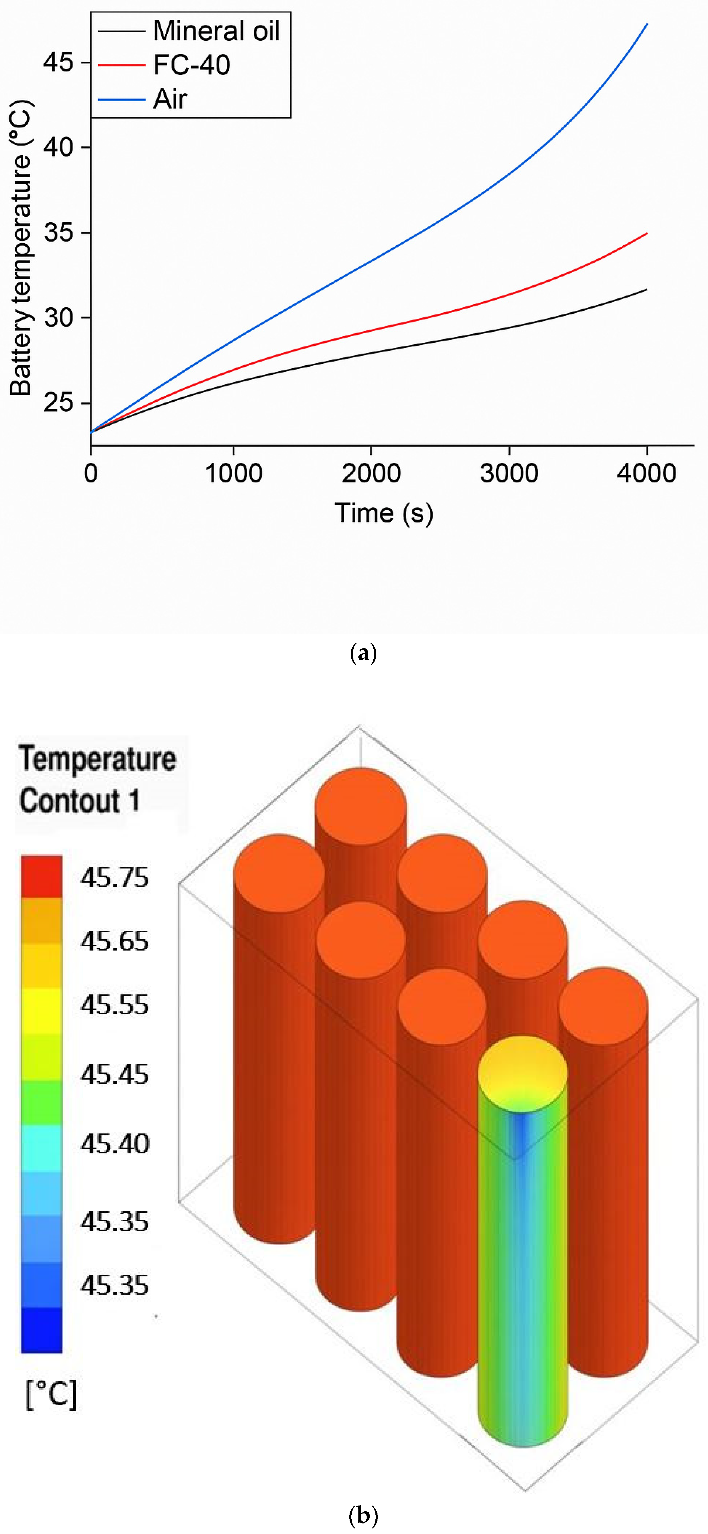
Figure 4a provides an assessment of battery thermal management systems utilizing three different fluids: air, mineral oil, and FC-40, with the aim of confirming the performance of each cooling fluid. The findings demonstrated that FC-40 dielectric fluid achieved a maximum temperature reduction of 8.4% compared with the use of mineral oil and a 45.7% reduction when using air. Simulation results show that FC-40 is a dielectric fluid with effective cooling properties.
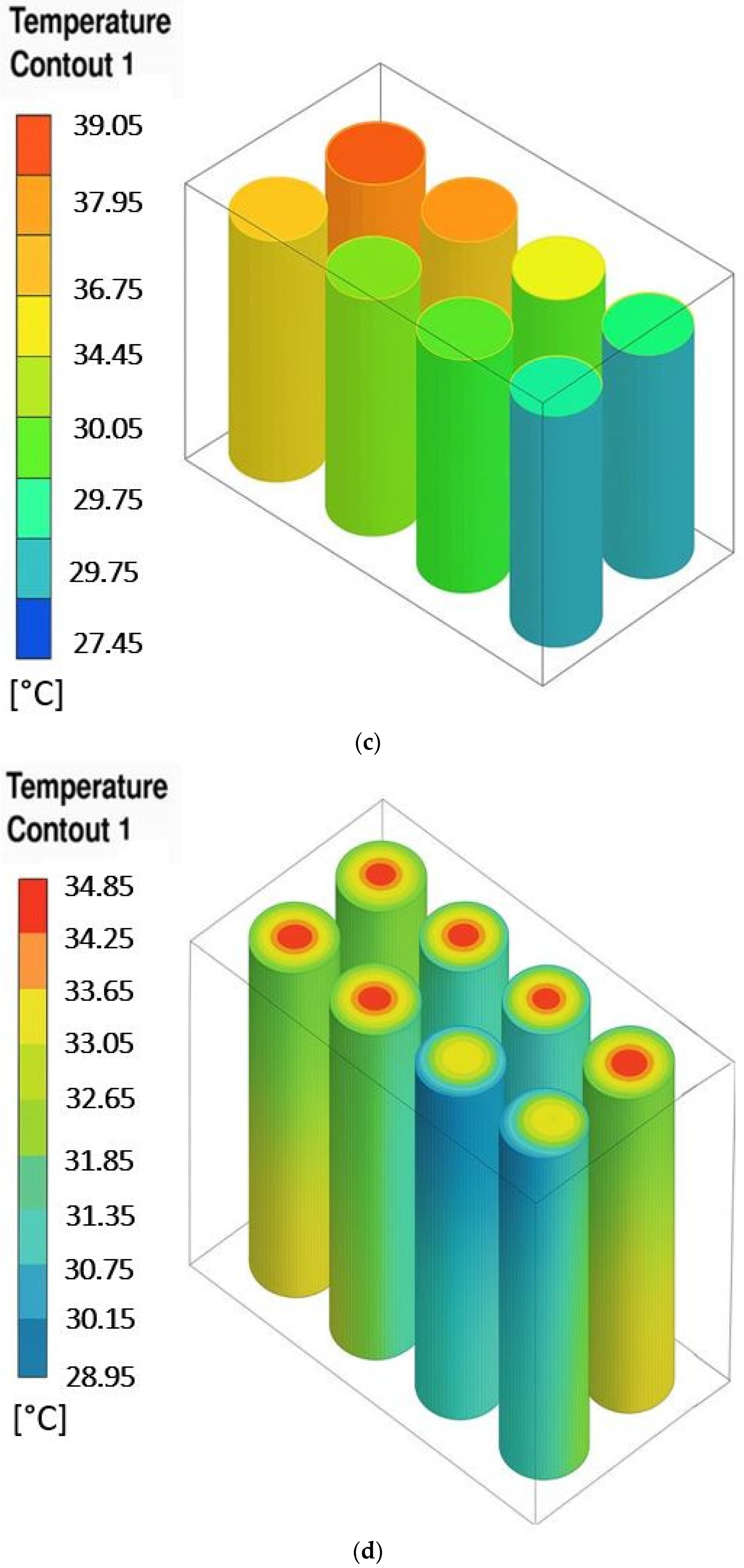
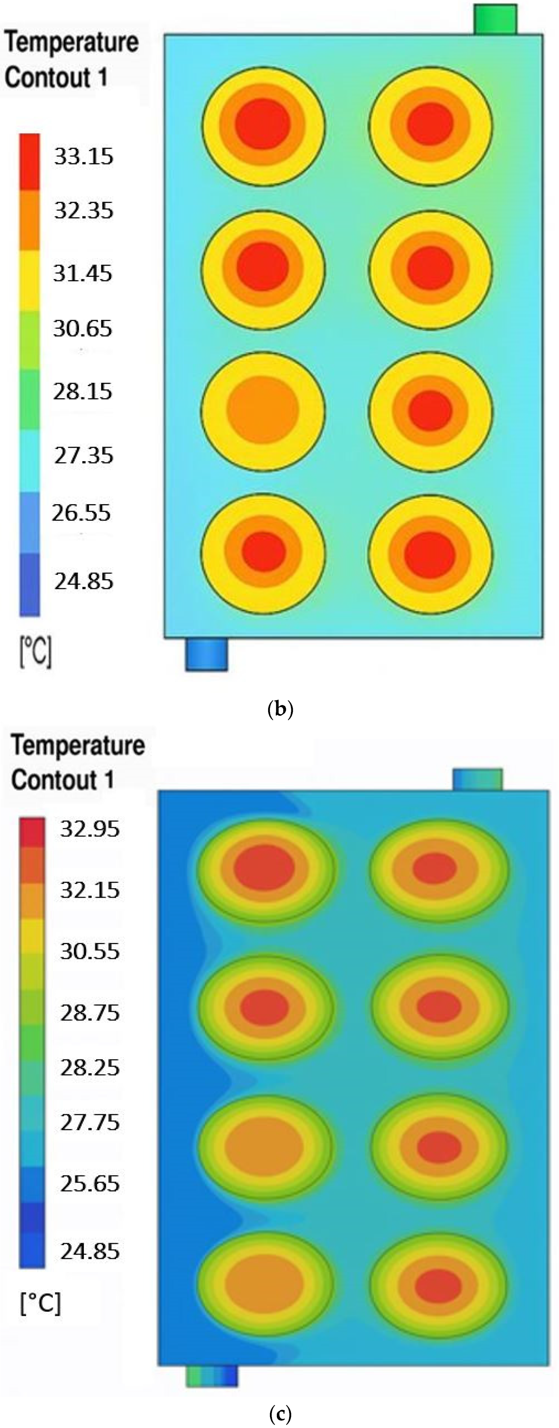
Figure 4b shows that the BTMS based on air cooling exhibits a significant hotspot across most battery cells. Poor heat removal leads to heat accumulation. Although the temperature uniformity indicator is low, the uniformly high temperatures indicate that the system is thermally ineffective. Figure 4c presents a BTMS based on immersion cooling using mineral oil, which shows improved heat dissipation. The figure illustrates a better overall temperature distribution, but with noticeable variation from top to bottom. Moreover, the temperature uniformity indicator is high, indicating less uniformity due to the presence of fluid-stagnation zones. Figure 4d presents a BTMS based on immersion cooling using FC-40, which shows the most uniform thermal field across all battery cells compared to the other coolants. The figure displays only a few small red zones, indicating minimized hotspots. The temperature uniformity indicator is lower, which means better temperature uniformity.
Table 4 presents a detailed comparative summary of the thermophysical properties and also the cooling performances of the three fluids studied in the research, air, mineral oil and FC-40, which highlights different critical parameters including thermal conductivity, specific heat capacity, density, viscosity, maximum cell temperature, and temperature uniformity indicator, which allows for a comprehensive evaluation of the effectiveness of each fluid in a BTMS based on immersion cooling. According to Table 4 and Figure 4, FC-40 stands out due to its superior temperature uniformity compared to mineral oil, a commonly used fluid in immersion cooling [30,31]. The findings confirm that FC-40 outperforms mineral oil and can be considered an optimal dielectric fluid for battery immersion cooling.

3.3. Flow Velocity Effects on FC-40 Dielectric Fluid in Battery Immersion Cooling

To analyze the effect of the flow velocity on the thermal performance of the LIB, four different flow velocities of the FC-40 dielectric at the system’s inlet were analyzed.
The temperature evolution over time for various coolant flow velocities is illustrated in Figure 5a. Hence, the findings show that increasing the flow velocity gradually enhances the system’s cooling capability which lowers the battery temperature significantly. At the end of the discharge cycle, the temperature rises at a flow velocity of 0.01 m/s is 5.7 °C and only 1.2 °C at a flow velocity of 0.15 m/s, which represents a 79% decrease. This finding underscores the efficiency of the immersion cooling systems using FC-40 in regulating battery temperature, particularly at elevated flow velocities.
Figure 5b further confirms these observations, showing that the battery cell’s maximum temperature decreases as the coolant velocity rises. The data reveal a clear trend of enhanced cooling performance with higher flow velocities, with the peak battery temperature decreasing from 30.6 °C at 0.01 m/s to 26 °C at 0.15 m/s. Therefore, higher coolant velocities improve heat removal and reduce localized overheating by increasing convective heat transfer, which is responsible for this temperature drop. Consequently, optimizing the coolant flow velocity is essential to balance effective heat dissipation and the energy consumption in immersion cooling approaches for LIBs.
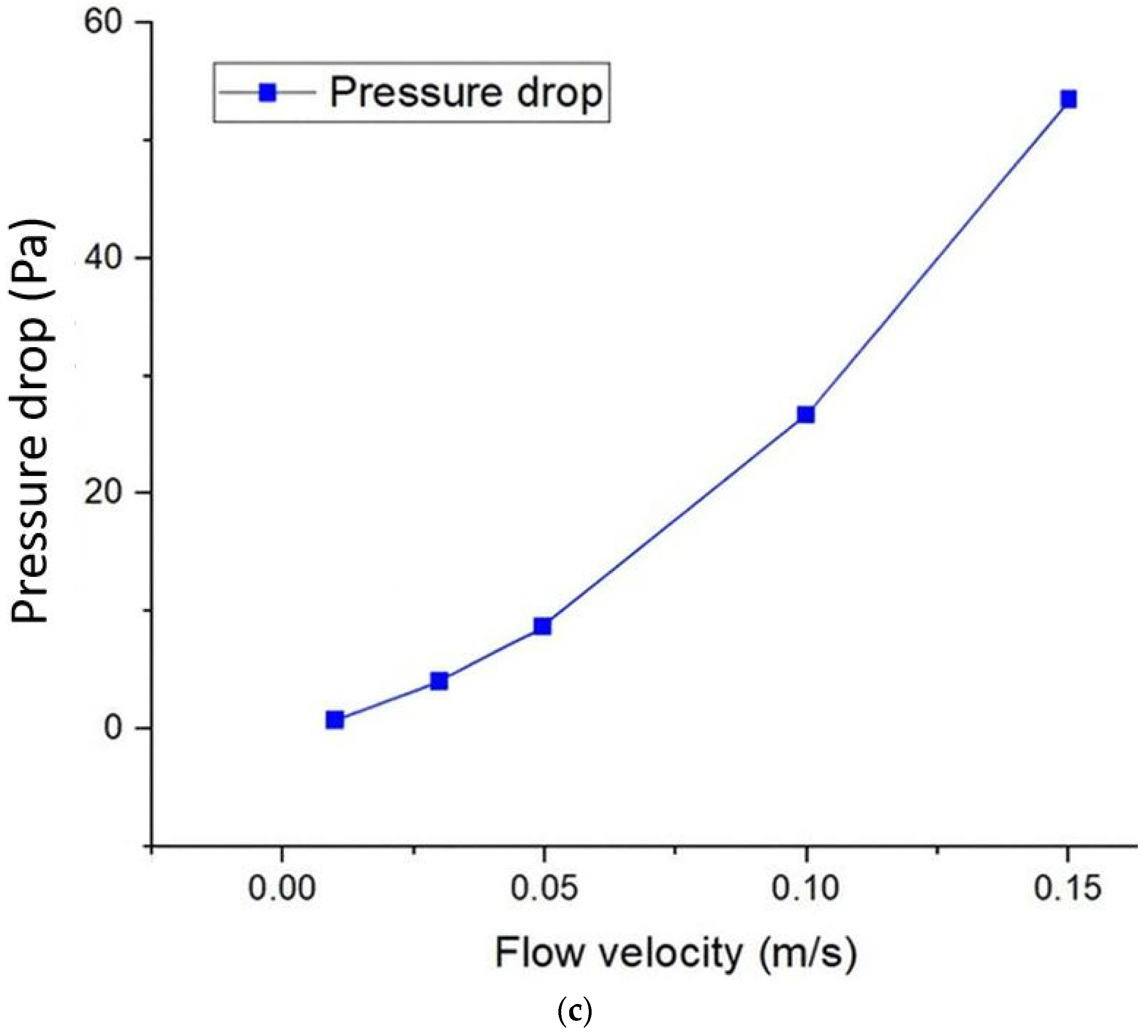
On the other hand, the pressure drop of the coolant is a critical factor in the design of a BTMS based on immersion cooling. When the flow velocity increases, the coolant’s pressure drop also rises, leading to a corresponding increase in the required pumping power. As presented in Figure 5c, the pressure drop increases linearly with flow velocity, which ranges between 0.7 and 53.4 Pa for flow velocities between 0.01 and 0.15 m/s. This confirms that at low flow velocities, the pressure drop remains minimal, thereby reducing the pumping power consumption.
To reduce pump energy demand, low flow velocities starting from 0.01 m/s were selected in this study, as it still enables effective thermal transfer due to the direct interaction between the dielectric fluid and the battery surface. Such low velocities are especially suitable for small-scale battery systems, where minimizing energy consumption while maintaining thermal control is essential.

3.4. Impact of Inlet/Outlet Diameter on the Battery’s Thermal Performance with FC-40 Immersion Cooling

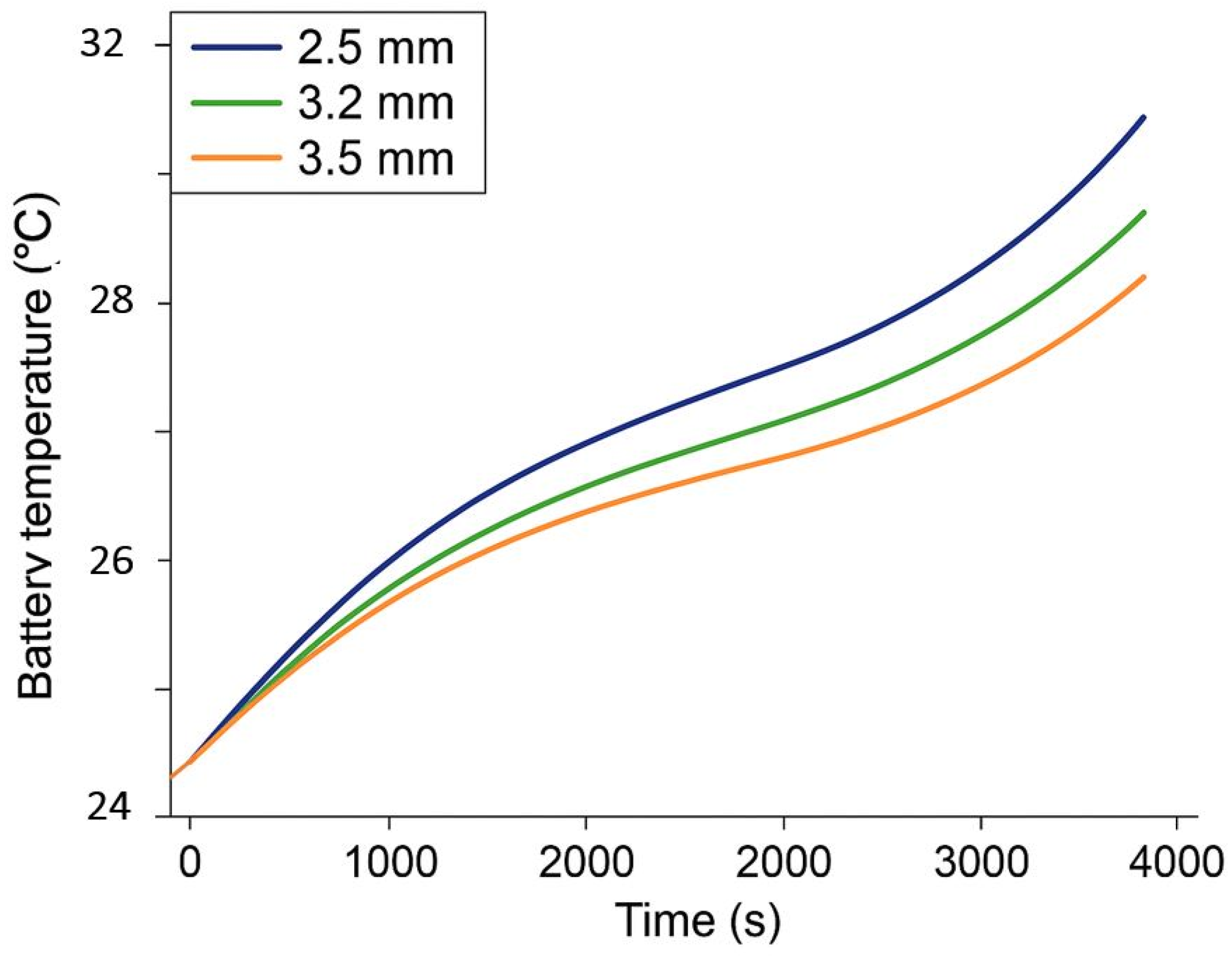
This research examines how different inlet and outlet diameters affect the thermal efficiency of battery immersion cooling, using FC-40 as the dielectric fluid. Indeed, three different diameters are studied (2.5 mm, 3.2 mm, and 3.5 mm) while maintaining a constant flow of 0.01 m/s, with an inlet temperature maintained at 25 °C and a discharge rate of 1C. The FC-40 coolant must enter via the inlet which captures the thermal energy produced from the LIBs via direct-contact immersion cooling and exit via the outlet. The aim is to investigate the impact of inlet/outlet diameter on the battery’s surface temperature regularity and overall thermal control efficiency.
Figure 6 explicitly illustrates that increasing the inlet and outlet diameters optimizes cooling efficiency through improved coolant flow. To be more precise, considering a 2.5 mm diameter where the maximum battery temperature is 30.5 °C, adopting a 3.5 mm diameter brings this temperature down to 29.2 °C. This corresponds to an approximate reduction of 4.3%. In other words, increasing the inlet/outlet diameter improves cooling performance, as larger diameters mean lower overall battery temperatures. Smaller diameters cause more significant temperature rises due to increased resistance to flow, which slows down the movement of coolant in the system and restricts heat release. On the other hand, larger diameters enhance heat transfer, leading to high cooling efficiency with FC-40.
Figure 7 presents nephograms of the top side, showing the temperature distribution in the battery cells as a function of increasing inlet and outlet diameters. When this diameter is increased from 2.5 mm to 3.5 mm, the uniformity index decreases from 10 to 8.1 °C for an increase of just 1 mm, corresponding to a reduction of 19%. These results indicate a more homogeneous temperature profile between battery cells as the diameter increases. In addition, the nephograms clearly display a concentration of hot spots on the upper surface. This phenomenon results from the direction of flow of the coolant, which enters at the bottom and exits at the top. As the liquid flows upwards, it progressively absorbs heat from the battery cells, raising its temperature and reducing its cooling efficiency at the top.

3.5. Effect of Discharge Rate on the Battery’s Thermal Performance with FC-40 Immersion Cooling

In this paragraph, the thermal response of the BTMS based on immersion cooling employing FC-40 as dielectric fluid is evaluated under different battery load conditions: 1C, 2C, 3C, 4C, and 5C.
As illustrated in Figure 8, the battery’s temperature gradually rose as the discharge rate increased, mainly because higher current loads led to greater internal heat generation. Compared to the reference at 1C, the temperature rose by approximately 23.03%, 42.20%, 59.48%, and 77.65% at 2C, 3C, 4C, and 5C, respectively.
These findings highlight the major difficulty of maintaining the optimum battery operating temperature and thermal homogeneity under high power operating conditions at the same time. To solve this problem, it is necessary to optimize the design of input and output configurations, as well as carefully adjust key cooling parameters, to ensure effective thermal control under high discharge conditions in battery cooling systems.

4. Conclusions

This study performed a numerical analysis of an eight-cell Li-ion battery model under immersion cooling with FC-40 dielectric fluid. The results illustrate that the dielectric fluid FC-40, attains a peak temperature up to 45.7% lower than air and 8.4% lower than the dielectric fluid, mineral oil. On the other hand, increasing the flow velocity of the coolant effectively improves the heat dissipation with a 79% reduction in battery temperature rise at 0.15 m/s compared to 0.01 m/s. However, this also leads to an increase in the pressure drop. Moreover, enlarging inlet and outlet diameters reduces the maximum cell temperature by up to 4.3%, enhancing thermal uniformity. Additionally, when the discharge rate increases, the maximum battery temperature also increases in the battery immersion cooling system, which implies that at high power conditions, strategies for the battery immersion cooling system are required to prevent overheating and to maintain safe operating conditions. Ultimately, the results highlight the strong technical capabilities of the dielectric fluid FC-40 for battery immersion cooling that demonstrate its ability to enhance the thermal efficiency of LIBs. The findings provide valuable guidance for the optimization of the next generation of battery thermal management systems, employing immersion cooling with FC-40, contributing to safer, more efficient, and higher performing electric vehicles. In future work, we will validate these numerical results through experimental testing and investigate the cost and weight impacts of using FC-40 fluid.

Author Contributions

Conceptualization, A.C.-O. and S.E.A.; methodology, A.C.-O. and S.E.A.; software, S.E.A.; validation, A.C.-O. and S.E.A.; investigation, S.E.A.; resources, R.H.; data curation, R.H.; writing—original draft preparation, S.E.A.; writing—review and editing, S.E.A. and A.C.-O.; visualization, R.H.; supervision, F.J.; project administration, A.C.-O. and F.J.; funding acquisition, A.C.-O. All authors have read and agreed to the published version of the manuscript.

Funding

This research received no external funding.

Data Availability Statement

The original contributions presented in this study are included in the article. Further inquiries can be directed to the corresponding author.

Conflicts of Interest

The authors declare no conflicts of interest.

Abbreviations

The following abbreviations are used in this manuscript:
AbbreviationNomenclature
BTMSBattery Thermal Management System Q r Heat generation
EVElectric Vehicle Q i r r Irreversible heat
CFDComputational Fluid Dynamics Q r e v Reversible heat
LIBs Lithium-Ion BatteriesICurrent
PCMPhase Change MaterialEVoltage
I/OInlet and Outlet R Internal resistance
SOCState of ChargeTTemperature
Greek SymbolstTime
ҨDiameter of the fluid inlet and outlet Q s Battery surface heat dissipation
ρ Density Q g e n Volumetric heat generation rate
λ Thermal conductivity of the coolant c p Specific heat capacity
k Thermal conductivity of the battery cell T r e f Reference temperature
V Velocity vectorPPressure
μ Dynamic viscositygGravity
βThermal expansion coefficient R e Reynolds number

References

  1. U.S. Environmental Protection Agency. Fast Facts on Transportation Greenhouse Gas Emissions. Available online: https://www.epa.gov/greenvehicles/fast-facts-transportation-greenhouse-gas-emissions (accessed on 25 August 2025).
  2. Alanazi, F. Electric vehicles: Benefits, challenges, and potential solutions for widespread adaptation. Appl. Sci. 2023, 13, 6016. [Google Scholar] [CrossRef]
  3. Tan, Y.; Li, Y.; Gu, Y.; Liu, W.; Fang, J.; Pan, C. Numerical study on heat generation characteristics of charge and discharge cycle of the Lithium-Ion battery. Energies 2023, 17, 178. [Google Scholar] [CrossRef]
  4. Afia, S.E.; Cano, A.; Arévalo, P.; Jurado, F. Energy Sources and Battery Thermal Energy Management Technologies for Electrical Vehicles: A Technical Comprehensive Review. Energies 2024, 17, 5634. [Google Scholar] [CrossRef]
  5. Paneerselvam, P.; SK, N.; Suyamburajan, V.; Murugaiyan, T.; Shekhawat, K.S.; Rengasamy, G. A review on recent progress in battery thermal management system in electric vehicle application. Mater. Today Proc. 2024. [Google Scholar] [CrossRef]
  6. Zhao, G.; Wang, X.; Negnevitsky, M.; Zhang, H. A review of air-cooling battery thermal management systems for electric and hybrid electric vehicles. J. Power Sources 2021, 501, 230001. [Google Scholar] [CrossRef]
  7. Qin, P.; Sun, J.; Yang, X.; Wang, Q. Battery thermal management system based on the forced-air convection: A review. Etransportation 2020, 7, 100097. [Google Scholar] [CrossRef]
  8. Luo, J.; Zou, D.; Wang, Y.; Wang, S.; Huang, L. Battery thermal management systems (BTMs) based on phase change material (PCM): A comprehensive review. Chem. Eng. J. 2021, 430, 132741. [Google Scholar] [CrossRef]
  9. Rahmani, A.; Dibaj, M.; Akrami, M. Recent Advancements in battery thermal Management Systems for enhanced performance of Li-Ion Batteries: A Comprehensive review. Batteries 2024, 10, 265. [Google Scholar] [CrossRef]
  10. Luo, Y.; Zhou, D.; Zou, Z.; Bi, C.; Yang, X.; Li, X.; Yang, X. A battery thermal management system integrating immersion preheating and immersion cooling. ACS Omega 2024, 9, 43523–43533. [Google Scholar] [CrossRef]
  11. Bao, R.; Wang, Z.; Gao, Q.; Yang, H.; Zhang, B.; Chen, S. Dynamic-static composite immersion cooling for improving thermal equalization behavior in lithium-ion battery packs. Energy 2025, 330, 136774. [Google Scholar] [CrossRef]
  12. Wang, Z.; Zhao, R.; Wang, S.; Huang, D. Heat transfer characteristics and influencing factors of immersion coupled direct cooling for battery thermal management. J. Energy Storage 2023, 62, 106821. [Google Scholar] [CrossRef]
  13. Zou, Z.; Xie, J.; Luo, Y.; Zhang, G.; Yang, X. Numerical study on a novel thermal management system coupling immersion cooling with cooling tubes for power battery modules. J. Energy Storage 2024, 83, 110634. [Google Scholar] [CrossRef]
  14. Yao, J.; Zhang, T.; Han, Z.; Chen, H.; Chen, H.; Liu, Z.; Huang, H. Study on the effect of immersion thermal management for high-current rate fast charging of 21700 Li-ion batteries. J. Energy Storage 2024, 85, 111061. [Google Scholar] [CrossRef]
  15. Hemavathi, S.; Kumaran, A.T.; Srinivas, S.; Prakash, A. Synthetic ester-based forced flow immersion cooling technique for fast discharging lithium-ion battery packs. J. Energy Storage 2024, 97, 112852. [Google Scholar] [CrossRef]
  16. Li, C.; Wang, Y.; Sun, Z.; Wen, X.; Wu, J.; Feng, L.; Wang, Y.; Cai, W.; Yu, H.; Wang, M.; et al. Two-phase immersion liquid cooling system for 4680 Li-ion battery thermal management. J. Energy Storage 2024, 97, 112952. [Google Scholar] [CrossRef]
  17. Liu, X.; Zhou, Z.; Wu, W.; Wei, L.; Hu, C.; Li, Y.; Huang, H.; Li, Y.; Song, Y. Numerical simulation for comparison of cold plate cooling and HFE-7000 immersion cooling in lithium-ion battery thermal management. J. Energy Storage 2024, 101, 113938. [Google Scholar] [CrossRef]
  18. He, Q.; Li, X.; Shan, W.; Zhang, W.; Wang, J.; Wang, Z.; Zheng, L. Numerical and experimental investigations on heat transfer characteristics and influencing factors of immersion cooling system for high-capacity prismatic lithium-ion battery. J. Energy Storage 2024, 104, 114518. [Google Scholar] [CrossRef]
  19. Le, Q.; Shi, Q.; Liu, Q.; Yao, X.; Ju, X.; Xu, C. Numerical investigation on manifold immersion cooling scheme for lithium ion battery thermal management application. Int. J. Heat Mass Transf. 2022, 190, 122750. [Google Scholar] [CrossRef]
  20. Patil, M.S.; Seo, J.; Lee, M. A novel dielectric fluid immersion cooling technology for Li-ion battery thermal management. Energy Convers. Manag. 2020, 229, 113715. [Google Scholar] [CrossRef]
  21. Wu, X.; Lu, Y.; Ouyang, H.; Ren, X.; Yang, J.; Guo, H.; Han, X.; Zhang, C.; Wu, Y. Theoretical and experimental investigations on liquid immersion cooling battery packs for electric vehicles based on analysis of battery heat generation characteristics. Energy Convers. Manag. 2024, 310, 118478. [Google Scholar] [CrossRef]
  22. Kumaran, A.T.; Hemavathi, S. Optimization of Lithium-ion battery thermal performance using dielectric fluid immersion cooling technique. Process Saf. Environ. Prot. 2024, 189, 768–781. [Google Scholar] [CrossRef]
  23. Zhao, L.; Tong, J.; Zheng, M.; Chen, M.; Li, W. Experimental study on the thermal management performance of immersion cooling for 18650 lithium-ion battery module. Process Saf. Environ. Prot. 2024, 192, 634–642. [Google Scholar] [CrossRef]
  24. Huang, H.; Li, W.; Xiong, S.; Luo, Z.; Ahmed, M. Single-phase static immersion-cooled battery thermal management system with finned heat pipes. Appl. Therm. Eng. 2024, 254, 123931. [Google Scholar] [CrossRef]
  25. Jiaqiang, E.; Yue, M.; Chen, J.; Zhu, H.; Deng, Y.; Zhu, Y.; Zhang, F.; Wen, M.; Zhang, B.; Kang, S. Effects of the different air-cooling strategies on cooling performance of a lithium-ion battery module with baffle. Appl. Therm. Eng. 2018, 144, 231–241. [Google Scholar] [CrossRef]
  26. 3M. 3MTM FluorinertTM Electronic Liquid FC-40. 2019. Available online: https://multimedia.3m.com/mws/media/64888O/3m-fluorinert-electronic-liquid-fc40.pdf (accessed on 1 January 2025).
  27. Muneeshwaran, M.; Lin, Y.; Wang, C. Performance analysis of single-phase immersion cooling system of data center using FC-40 dielectric fluid. Int. Commun. Heat Mass Transf. 2023, 145, 106843. [Google Scholar] [CrossRef]
  28. Liu, J.; Ma, Q.; Li, X. Numerical study on heat dissipation performance of a lithium-ion battery module based on immersion cooling. J. Energy Storage 2023, 66, 107511. [Google Scholar] [CrossRef]
  29. Williams, N.; Trimble, D.; O’Shaughnessy, S. Liquid immersion thermal management of lithium-ion batteries for electric vehicles: An experimental study. J. Energy Storage 2023, 72, 108636. [Google Scholar] [CrossRef]
  30. Liu, J.; Chen, H.; Yang, M.; Huang, S.; Wang, K. Comparative study of natural ester oil and mineral oil on the applicability of the immersion cooling for a battery module. Renew. Energy 2024, 224, 120187. [Google Scholar] [CrossRef]
  31. Satyanarayana, G.; Sudhakar, D.R.; Goud, V.M.; Ramesh, J.; Pathanjali, G. Experimental investigation and comparative analysis of immersion cooling of lithium-ion batteries using mineral and therminol oil. Appl. Therm. Eng. 2023, 225, 120187. [Google Scholar] [CrossRef]
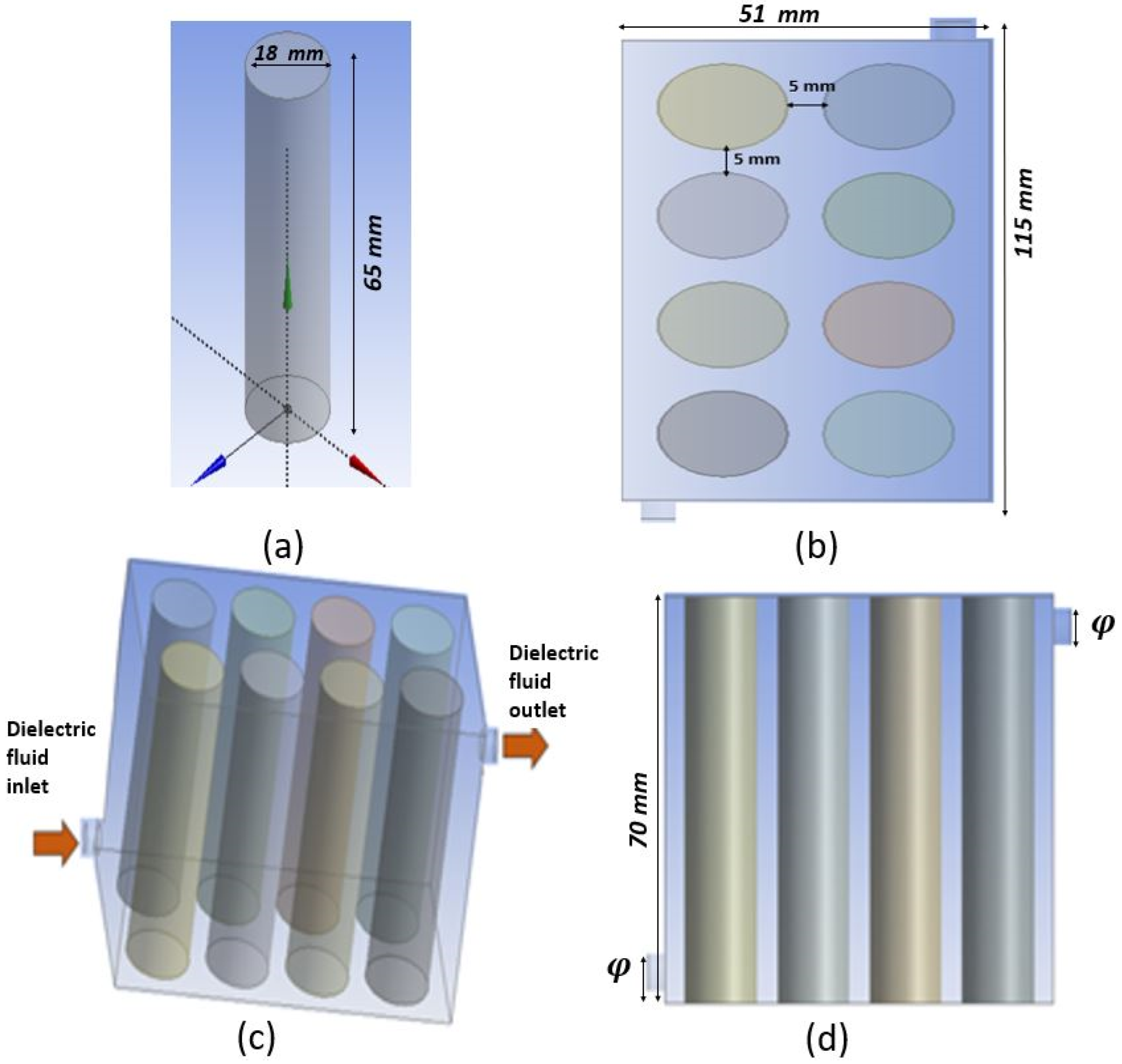
Figure 1. Illustrations of the LIB’s immersion cooling system: (a) Li-ion cell model, (b) top side of the battery module, (c) geometry model diagram, and (d) lateral view of the battery module.
Batteries 11 00397 g001
Figure 2. Mesh configuration applied to the battery module in immersion cooling analysis: (a) detailed battery cell mesh, (b) top view of the cooling channel arrangement, and (c) battery surface temperature under 4C discharge conditions for different mesh element sizes (mesh independence test).
Batteries 11 00397 g002
Figure 3. Validation: case study—LIB-18650 Jiaqiang E. et al. [25].
Batteries 11 00397 g003
Figure 4. (a) Temperature of the Li-ion battery under three cooling fluids: air, mineral oil, and FC-40. (bd) CFD temperature contours of the battery cells under the respective cooling fluids: (b) air, (c) mineral oil, and (d) FC-40.
Batteries 11 00397 g004aBatteries 11 00397 g004b
Figure 5. Effect of coolant flow velocity on (a) battery temperature rise, (b) maximum battery temperature, and (c) pressure drop in immersion cooling.
Batteries 11 00397 g005aBatteries 11 00397 g005b
Figure 6. Effect of I/O diameter on total battery temperature rise in immersion cooling using FC-40.
Batteries 11 00397 g006
Figure 7. Temperature distribution nephogram for various battery inlet and outlet diameters: (a) 2.5 mm, (b) 3.2 mm, and (c) 3.5 mm.
Batteries 11 00397 g007aBatteries 11 00397 g007b
Figure 8. Effect of the discharge rate on total battery temperature evolution under FC-40 immersion cooling.
Batteries 11 00397 g008
Table 1. Properties of the lithium-ion battery.
PropertySpecification
Cathode substance L i N i x C O y M n z O 2
Anode substanceGraphite
Cell length (mm)65
Cell diameter (mm)18
Nominal voltage (V)3.7
Nominal capacity (Ah)2.6
Specific heat capacity ( J . k g 1 . K 1 )1200
Table 2. Mesh independence test for simulation of the battery.
Mesh ConfigurationNumber of ElementsNumber of Nodes
Mesh-1514,924208,219
Mesh-2901,284355,905
Mesh-31,459,459603,667
Table 3. Simulation cases for LIB immersion thermal analysis under different conditions.
CaseCoolantFlow Velocity (m/s)Discharge RateInlet and Outlet Diameter (mm)
1Air0.011C2.5
2Mineral oil0.011C2.5
3FC-400.011C2.5
4FC-400.031C2.5
5FC-400.051C2.5
6FC-400.11C2.5
7FC-400.151C2.5
8FC-400.011C3.2
9FC-400.011C3.5
10FC-400.012C2.5
11FC-400.013C2.5
12FC-400.014C2.5
13FC-400.015C2.5
Table 4. Comparative properties and cooling performance of air, mineral oil, and FC-40 for BTMSs based on immersion cooling.
Performance MetricAirMineral OilFC-40
Density (kg/m3)1.2251080.921855
Specific heat (J/(kg K)1006.43896.661100
Thermal conductivity (W/m K)0.02420.1490.065
Viscosity (kg/m s)1.79 × 10−50.0750.0041
Max cell temperature (°C)45.633.0330.5
Temperature uniformity indicator (°C)0.411.556
Disclaimer/Publisher’s Note: The statements, opinions and data contained in all publications are solely those of the individual author(s) and contributor(s) and not of MDPI and/or the editor(s). MDPI and/or the editor(s) disclaim responsibility for any injury to people or property resulting from any ideas, methods, instructions or products referred to in the content.